1
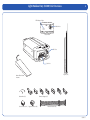
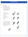
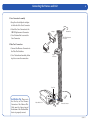
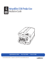
Networkfleet 3500 Product Line
Installation Guide
Light/Medium Duty (L3500)
|
Heavy Duty (H3500)
www.networkcar.com/fleet | Customer Care: (866) 227-7323 [email protected]
|
Universal (U3500)
Table of Contents
Getting Started
Registration form.............................................................................................................3
Light/Medium Duty (L3500)
Unit Overview..................................................................................................................4
Harness Assembly Instructions.....................................................................................5
Connecting the Harness and Unit.................................................................................6
Connecting to the OBD-II Port......................................................................................7
Heavy Duty (H3500 )
Unit Overview..................................................................................................................8
Connecting to the DLC Port . ........................................................................................9
Universal (U3500 )
Unit Overview................................................................................................................10
Connecting to Ground and Power.........................................................................11-12
Common Installation
Installing Antenna.........................................................................................................13
Reconnecting the Antenna Wires................................................................................14
Verifying Successful Installation.................................................................................15
Creating Tamper Evidence......................................................................................16-17
Securing the Device & Completing Installation........................................................18
Appendix
Troubleshooting Light Indicators................................................................................19
Frequently Asked Questions...................................................................................20-21
Contacting Networkcar................................................................................................22
v.3500.1.6
Getting Started
Fill out the enclosed registration form
before completing installation.
Record the following information:
Vehicle Identification Number (VIN)
License Plate
• Year
• Model
• Make
• Unit’s Serial number (10 digits)
•
•
Installation Tip: Metal walls and
tall buildings may interfere with
the reception from GPS satellites
and the cellular network. Perform
installation when the vehicle
is in clear view of the sky. Conduct
final installation verification after
the vehicle has been running outside
for 5-10 minutes.
v.3500.1.6
Light/Medium Duty (L3500) Unit Overview
LED Indicator Lights
Cellular Port
Back of Unit
GPS Port
Data Port
Zip Ties (X7)
Interior Glass-Mount
Antenna
Retainer Bar (X1)
Core Connector (X1)
Harness Adapters (X7)
Bypass Connector (X1)
Harness Flat Cable (X1)
v.3500.1.6
Harness Assembly Instructions
1. Select an Adapter
Select an adapter that most resembles the
shape of the OBD-II port of the vehicle.
Use these guidelines to match an adapter
(each adapter is stamped with a number)
to a vehicle it is most likely to fit.
Ford, GM (1) or (6)
Honda, Lexus, Toyota, Chrysler (2)
Toyota*, Chrysler* (2a)
Saturn (3)
Mercedes, BMW (4)
Porsche, Audi, Volkswagen (5)
Volvo (6)
Saab (7)
* For certain Toyota and Chrysler vehicles,
you may need to adjust the #2 adapter by
removing the clips on the top and bottom
of the adapter. Below is an example of the
adjusted adapter labeled (2a).
(1)
(4)
(2)
(5)
(3)
(6)
(7)
(2a)
v.3500.1.6
Connecting the Harness and Unit
1. Core Connector Assembly
1. Snap
2. Attach
the selected plastic adapter
to the back of the Core Connector.
the Core Connector to the
OBD-II Replacement Connector.
Retainer Bar
Adapter
3. Use
a Retainer Bar to secure the
Core Connector.
OBD-II Replacement
Connector
2. Data Port Connection
1. Connect
the Harness Connector to
the Data Port Interface.
2. Use
Core Connector
a Networkcar branded yellow
zip tie to secure the connection.
Bypass
Connector
Data Port
Key
Installation Tip: Please note
that the key on the Harness
Connector of the Harness Flat
Cable must be facing toward
the bottom of the Networkfleet
device to properly connect.
Networkfleet Unit
Harness Connector
v.3500.1.6
Connecting into the OBD-II Port
1. With the vehicle’s engine OFF, remove the OBD-II port.
• The OBD-II Connector may be hidden behind
a hush panel.
• To remove the connector, you may need to remove
screws or depress the clips.
2. Connect the Bypass Connector to the vehicle OBD-II port that
was previously removed.
3. Attach the Core Connector to the position where the original
OBD-II connector was installed. Secure it with the screws or
clips removed from the OBD-II Connector’s original position
(if applicable).
to vehicle
Original OBD-II Port
Bypass Connector
Networkfleet Unit
Core Connector
Dashboard
To complete installation proceed to page 13
v.3500.1.6
Heavy Duty (H3500) Unit Overview
LED Indicator Lights
Cellular Port
Bypass
Connector
Back of Unit
Core
Connector
GPS Port
6-Pin Harness (X1)
Data Port
Interior Glass-Mount
Antenna
Bypass
Connector
Core
Connector
Zip Ties (X7)
9-Pin Harness (X1)
v.3500.1.6
Connecting into the Diagnostic Link Connector (DLC) port
1. With the vehicle’s engine OFF, unscrew the DLC port from its
position under the dashboard*. In most cases, the DLC port is located
under the dashboard on the left side of the steering wheel, facing
toward the floorboard.
2. Plug the Bypass Connector of the harness into the DLC port that was
previously removed from the vehicle in step 1. For the 9-pin connector,
turn the rotating cap clockwise to lock into place.
3. Mount the Core Connector of the harness into the place in which
the DLC port originally resided.
*Note: DLC Port Connector may also be located near or behind the driver seat.
to vehicle
Original DLC Port
Bypass Connector
Networkfleet Unit
Core Connector
Dashboard
To complete installation proceed to page 13
v.3500.1.6
Universal (U3500) Unit Overview
10
The Universal unit can be installed in light, medium and heavy vehicles. It is a GPS data only
device and does not read diagnostic data from the vehicle’s engine computer.
LED Indicator Lights
Cellular Port
Harness
Connector
Back of Unit
GPS Port
Data Port
Interior Glass-Mount
Antenna
Zip Ties (X7)
Red
Blue
Black
v.3500.1.6
Connecting to Ground and Power
11
Black Wire - Ground
•
ith the vehicle’s engine OFF, attach the Black Wire directly to a chassis ground point
W
or to a ground line (chassis ground) by splicing directly to a ground lead or by using a wire
tap (recommended).
Red Wire - Continuous Power
•
ith the vehicle’s engine OFF, use the voltmeter to locate a 12-volt BATTERY lead and attach
W
the Red Wire by splicing directly to the lead or by using a wire tap (recommended). If attaching
to a fused lead or using an inline fuse (not necessary), verify that it is at least 5 amps.
•
e careful not to confuse a “Retained Accessory Power (RAP)” line with a true
B
Continuous Power line (12 volt, always ON line).
•
To determine a true Continuous Power source:
1) Ensure the Driver Door is OPEN
2) Select a wire
3) W
ith vehicle’s engine OFF, use a voltmeter to measure the DC voltage on the wire.
It should show 12 VDC or higher.
Note: Please ensure that the Driver
Door is OPEN during the ENTIRE
installation process.
v.3500.1.6
Connecting to Ground and Power
12
Blue Wire - Switched Power
ith the vehicle’s engine OFF, use the voltmeter to locate an IGNITION line with switched
W
power and attach the Blue Wire to the line by splicing directly to the lead or by using a wire tap
(recommended).
•
• Do
•
Do NOT use accessory Power.
•
To determine a switched power source:
NOT use an inline fuse on this line.
1) Ensure the Driver Door is OPEN
2) Select a wire
3) With vehicle’s engine OFF use voltmeter to measure the DC voltage on the wire. It should
show 0 VDC.
4) Start the engine and confirm that the voltage of the same wire
is 13.1 VDC or higher
5) Turn the vehicle’s engine OFF and confirm that the voltage of the same wire is 0 VDC
Constant Power (Battery)
Red Wire
Networkfleet Unit
Switched Power
Black Wire
Blue Wire
Ground
To complete installation proceed to next page
v.3500.1.6
Installing Antenna
13
1. Use enclosed alcohol preparation pad to clean the inside windshield where the antenna is
to be placed. For proper operation, the antenna should be placed on flat, clear glass on the
driver’s side interior lower corner of the windshield.
Ensure that the antenna does not extend more than 4 ½ inches from the bottom of the
interior windshield and is located outside the area swept by the windshield wipers.
Do NOT place the antenna in the following areas:
• Behind
stickers or decals already on the glass
the shade band of the glass
• On a curved area of the glass
• On a moist or damp area of the glass
• On an area that will obstruct the driver’s view
• On
2. Run the cables up the door seam or up through the dashboard.
3. Remove the protective-strip from the antenna to expose the adhesive.
4. Carefully affix the antenna to the glass that was prepped in Step 1.
Press the antenna firmly to the glass while
being careful not to damage the antenna.
Windshield
Installation Tip: Please note that
the ideal temperature range to
perform the installation is between
70°F to 100°F (21°C to 38°C) with
a minimum suggested application
temperature of 60°F (15°C).
4 ½ inches max
Interior Glass-Mount
Antenna
v.3500.1.6
Reconnecting the Antenna Wires
GPS Antenna Wire (blue)
•
• Although
•
14
Cellular Antenna Wire (maroon)
I f the antenna becomes disconnected from the unit during installation, make sure
to reconnect the antenna wires to the device. Each antenna wire should be plugged
into the appropriate jack labeled on the end of the unit.
the antennas may appear similar, please note that the cellular antenna is
encased in a maroon end cap and the GPS antenna is encased in blue.
ach antenna wire should easily snap into the appropriate jack. No solder or excessive
E
force is necessary. Note that the cellular antenna connector should be snapped in at
GPS Antenna Port
Front of Unit
v.3500.1.6
Verifying Successful Installation
15
1. Start the vehicle’s engine. All lights (Red, Yellow, and Green) on the device should
begin blinking rapidly (twice a second).
2. The device is operating normally when the rapid blinking ceases and the Green and
Yellow lights begin to blink in a slow pattern (ON for 5 seconds and OFF for 1 second).
The Red light pattern will continue to vary and should not be used to verify installation.
3. The device should take no longer than 10–15 minutes after the engine is started to reach
normal operating mode which will indicate a successful installation.
Green light
(GPS)
Red light
(Cellular)
Yellow light
(Vehicle)
Cellular Antenna Port
Back of Unit
v.3500.1.6
Creating Tamper Evidence
16
1. For the Cellular Antenna, slide the end of the
Networkcar branded yellow zip tie into the
cut-away section on the back left side of the
device. If the antenna is plugged in correctly
(at a 90° angle) the zip tie should slide through
the top of the cellular antenna plastic cap. Lock
the zip tie and cut the excess plastic to prevent
the antenna cable from being unplugged.
Cellular Antenna Port
2. For the GPS antenna, slide the end of the
Networkcar branded yellow zip tie into the cutaway section of the top right side of the device.
If the antenna is plugged in correctly, the zip tie
should slide through the top of the GPS antenna
plastic cap. The zip tie should now be looped
through the plastic end cap of the device, as well
as the plastic cap of the antenna cable. Lock the
zip tie and cut the excess plastic to prevent the
antenna cable from being unplugged.
GPS Antenna Port
Note: For easier threading of the zip tie through the plastic cap of
each antenna, bend the end to curve it upward.
v.3500.1.6
Creating Tamper Evidence
3a. Once the Light/Medium Duty vehicle harness
is plugged in, slide a Networkcar branded yellow
zip tie through the slots provided in front of the
harness connector, moving from the left to right
side of the device (Threading the tie in the
opposite direction may cause interference with
the GPS antenna connector). Once the zip tie is
in place across the back of the harness connector,
tighten and remove the excess plastic. If possible,
position the zip tie so that the “DO NOT
REMOVE” message is showing.
3b. Once the Heavy Duty or Universal vehicle
harness is plugged in, slide a Networkcar
branded yellow zip tie through the slots
provided in the center of the top and bottom
sides of the device end cap. Thread the zip
tie in between the black and blue wires on
the harness. Once the zip tie is in place across
the back of the harness connector, tighten and
remove the excess plastic. If possible,
position the zip tie so that the “DO NOT
REMOVE” message is showing.
17
Light/Medium Duty Harness
Heavy Duty Harness
v.3500.1.6
Securing the Device & Completing Installation
18
1. Before securing the device under the dashboard, make
sure that you have recorded the VIN, hardware serial number,
and odometer reading on the registration form. Also verify
that you have checked the light indicators. After installation,
provide the registration form to the fleet manager for delivery
to Networkcar.
2. Use zip ties to fasten the hardware securely
to a stable bracket or wire bundle under the
dash.
3. Loosely bundle the antenna’s excess cable
and secure it away from moving parts.
Bundling it tightly will have a negative
effect on its performance.
v.3500.1.6
Appendix: Troubleshooting Light Indicators
Issue: Solution:
Issue:
Solution:
Issue:
Solution:
Issue:
Red light continues to blink rapidly
– Verify antenna connection to device and assess antenna for damage.
– Verify antenna is installed correctly on the interior glass.
– Contact Customer Care to confirm network coverage availability.
Yellow light continues to blink rapidly
– Contact Customer Care to verify engine computer compatibility.
– If incompatible, install a Universal device (U3500).
Green light continues to blink rapidly
– With
the vehicle’s engine OFF, unplug the device for 3 minutes and
check each item below before reconnecting.
• Disconnect
the GPS Antenna wire and check the antenna wire
and connector for damage.
• Reconnect the GPS antenna wire connector to the GPS port.
• Reconnect device, start engine and keep the vehicle running or
drive it for 10-15 minutes.
Yellow light stays on solid
Solution:
– Verify cellular antenna connection to device (maroon end cap).
– Verify that the antenna was properly installed.
–M
ake certain that the antenna has a clear view of the sky and is
– Wait
Issue:
Solution:
19
not blocked by underground parking structures or trees.
15 minutes with the vehicle’s engine on.
Green light stays on solid
– Verify GPS antenna connection to device (blue end cap).
– Verify that the antenna was properly installed.
–M
ake certain that the antenna has a clear view of the sky
not blocked by underground parking structures or trees.
and is
v.3500.1.6
Frequently Asked Questions
20
General
Q: What is the power draw for the device?
A:Normal Operating Mode 200 mA @ 12 V
Sleep Mode 21 mA @ 12V
Q: Are the harnesses interchangeable between 3100, 3400 and 3500 product lines?
A: Yes as long as it is the same type of unit. For example, a H3100 harness can be used on a
H3500 unit.
Q: Are the devices interchangeable? Can I use a L3500 device with a H3500 harness and
install it on a heavy duty vehicle?
A: No, each device has special software that makes it only compatible with a certain class
of vehicles.
• L3500 (1996 and newer vehicles Class 1-6 Light Duty)
• H3500 (1996 and newer vehicles Class 7-8 Heavy Duty)
• U3500 (Any vehicle - Universal)
Q: When installing the U3500 device, are fuses involved or can the device be “wired hot”?
A: We recommend splicing the U3500 harness to fused leads, though the device can be
“wired hot” since there is an internal re-settable fuse. An inline fuse is not necessary,
however if one is used, it should be at least 5 amps.
v.3500.1.6
Frequently Asked Questions
21
Antenna
Q: Are the antennas interchangeable between the 3100, 3400 and 3500 product lines?
A: No.
Q: Can the glass mount antenna be installed in the A-Pillar?
A: No, the glass mount antenna is designed so that it will only function properly with a clear
view of the sky which is best achieved by placing it on the glass windshield.
Q: I need to do a unit transfer. Can I re-use the antenna? How do I remove it from the glass?
A: No, you cannot re-use the antenna on another vehicle. The adhesive on the antenna is
one-time use only and will not function properly after it is removed.
* Re-installation kits are available - contact Customer Care at (866) 227-7323
for more information.
Instructions for Antenna Removal
Because of the strength of the antenna adhesive, use a razor or Goo Gone (a household
solvent) for removal.
1. To remove the antenna with a razor, peel a small section of the antenna off of the glass
and slide the razor between the glass and the antenna.
2. Using a sawing motion, carefully remove the antenna from the glass and discard.
v.3500.1.6
Contacting Networkcar
22
If you have any additional questions, you may contact
Networkcar Customer Care:
Toll Free Number: 1-866-227-7323
Email: [email protected]
Networkcar
4510 Executive Drive Suite 315
San Diego, CA 92121
www.networkcar.com
Fax: 858-450-3246
v.3500.1.6