1
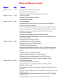
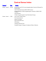
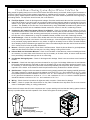
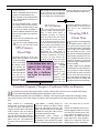
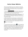
Central Sense Bulletins All Central Sense Bulletins have been combined into this single Acrobat document. This allows the user to search by keyword or phrase for the desired information. There are several ways to search for bulletins. 1. The arrows on the Acrobat toolbar allow you to search one page at a time, or go directly to each end of the document. This is useful for multi-paged bulletins. 2. The bookmarks feature. Click on any icon on the left and it will go to that particular page. Use the scroll bar on the left to search up and down for bookmarks. This feature works well when used with the indexes. 3. The index contains a brief description of each Central Sense Bulletin, the date it was released, and the corresponding part number. Use the index to view information for each letter, then click on the icon of the same name in the bookmarks. Click here to go to the index pages. Or . In the Acrobat Find 4. To use the search function, click here dialog box enter the word or phrase you want to search for, then press Find. Acrobat will search until it finds the first occurrence of this word or phrase. To continue searching, press the F3 key on your keyboard. This can be very valuable when the user does not know which Central Sense Bulletin contains the desired information. Central Sense Index Volume # Date Volume 4, Issue 1 10/1/01 Articles New Propane Low Pressure Kit (LPLP01) Special Analysis Part(s) Return Tag Check Home Heating System Before Winter Cold Sets In Volume 3, Issue 2 4/1/00 InfoFinder Updates Package Unit Bubble Wrap Packaging ECM Motor Power Heads Volume 3, Issue 1 1/1/00 InfoFinder Updates, Package Heat Pumps and Package Coolers now have external drains, Defrost Control Board Confusion New Two-Stage White-Rodgers Gas Valve for 40" 80% & 90% Furnaces Programming change to the ECM used in PGD48,060C 090, 115, 1402E Common use of primary limits between40” 80% GCIC115**40 and GCIC140**50 Furnaces New Primary Limit Usage on 40” 80% GUICX50 Furnaces Revision to Standpipe Bag Assembly for 40” 90% GUCA and GCCA and 95% GUVA Furnaces Heating Orifices for RHA Heat Pumps Volume 2 Issue 2 7/1/99 New Modular Format for Service Manuals, Package Heat Pump Loss of Charge Switch, RTV Sealant in a Pressurized Can, New Induced Draft Blowers for 40" 80% GUIC, GCIC and GUID Furnaces New Manual Reset Limits for 80% and 90% Furnaces and Package Gas Units Package Heat Pump Condensate Drains Revised Air Circulator Motors for 40” 80% Furnaces Replacement Motor Mounting Assembly for 48” 90% Furnaces Service Replacement Rollout Limits for GUD115X50B Furnaces Volume 2 Issue 1 4/1/99 Product Quality Reports, Package Heat Pump Defrost Settings, New 10 x 8 Blower Assembly for 40" 80% GUI(C,D)070__40 and GCIC070__40 Furnaces, Better Application of Blower Compartment Insulation on GUCA and GCCA Furnaces New and Improved Integrated Ignition Controls for 40" 80% GUIC, GCIC and GUID Furnaces Alternate Horizontal Vent Termination (Dual Pipe) for 40" 90% GUCA and GCCA Furnaces 40" 90% GUCA & GCCA Furnace Condensate Drain Clamps Central Sense Index Volume # Date Volume 1 Issue 2 10/1/98 Articles Revised 80% and 90% Furnace Integrated Ignition Controls to Eliminate Fan Dropout Noise Flame Rectification Kit for GUIB & GCIB Furnaces Future Availability of 50A52 Integrated Ignition Controls for GUIB & GCIB Furnaces GE ECM Motors FTK02A Integrated Ignition Control Part Number Change Volume 1 Issue 1 1/1/98 90% Furnace Venting Tables Dirty Socks Syndrome Norton 271A Igniter 80% Furnace Door Clips ECM Motors Sweating CHA Drain Pans Dewobble Program, Changes to Condenser Grilles on Remotes Volume 4, Issue 1 October 2001 Amana HAC Technical Services New Propane Low Pressure Kit (LPLP01) Throughout the heating industry we have seen 80% and 90% furnaces soot up due to various reasons, one of which is due to propane levels in the storage tank dropping to low causing insufficient gas pressure for the burners to operate properly which in turn causes sooting in the heat exchanger. A new accessory has been slated to be released by this fall by Amana for use on our gas furnaces when converted to propane gas use. This new kit is known as the LPLP01 and should be used with all propane gas furnaces installations. The new LPLP01 kit consists of the following: • • Propane Low Pressure Switch Switch to Gas Valve Piping o Close Nipple o Tee • Switch to Gas Valve Wiring o Single Stage Harness o Two-Stage Harness • Propane Low Pressure Kit Label • Wiring Diagram • Installation Instructions The following drawing illustrates the LPLP01 in a typical installation. Gas Valve LP Low Pressure Switch Special Analysis Part(s) Return Tag Occasionally Amana requests parts or products be returned for analysis, to ensure these parts or products are returned to the appropriate parties we have released a new “Special Analysis Part(s) Return Tag”. These return tags are available from the Technical Services department in Fayetteville, TN. To prevent mishandling or loss this “Special Analysis Part(s) return Tag” must be attached to the exterior of the carton and clearly visible for all parts or units where Technical Services or Regional Service Manager has requested the part or unit be returned for analysis. Without this tag it is very difficult for our receiving department to determine what is being returned and why. Along with this part(s) return tag, a copy of the “Return Authorization” must be attached to the outside of the carton on any unit or “Readable Copy of Warranty Tag” must be attached to part(s) being returned for inspection and/or analysis in order to be properly coded and entered into the warranty system and proper credit issued to the distributor or dealer. Note: All bar code labels on the carton must be removed before any unit is shipped back to Amana. Following these return procedures will help to ensure parts or products are returned to the appropriate party and that credits are issued with minimal delay. Tags: Heating & Air Conditioning ® Plug from Gas Valve ( Temporary Pressure Tap Location ) SPECIAL ANALYSIS PARTS RETURN TAG Amana Heating & Air Conditioning 1810 Wilson Parkway Fayetteville, TN 37334 Tee Gas Supply Line The LPLP01 will monitor the gas line pressure and will disable the units’ gas valve if the line pressure drops below acceptable levels. This kit provides control over the unit gas valve by routing the gas valve wiring through the supplied pressure switch. To enable proper fit-up, the pressure switch kit must be installed before connecting the gas supply line to the gas valve. For new unit installations, the kit hardware may be fitted to the gas valve while the gas manifold is removed for LP gas orifice conversion. For existing installations, the gas valve line must be disconnected from the gas valve to allow fitting of kit hardware. To Whose Attention in Customer Service Dept. Part No. Model No. Serial No. Mfg. No. Return Authorization No. INSTRUCTIONS 1. Only when special parts analysis is required. F O R 2. Readable copy of warranty tag also attached. USE 3. Part to be shipped separately from regular returns. 20343501 Heating&Air Conditioning ® Comfort. Quality. Trust. Central Sense Check Home Heating System Before Winter Cold Sets In Many people are getting ready to turn on the heat for winter. But before turning on the heat, Amana urges homeowners to have their fuel-burning home heating systems inspected by a qualified service technician. A qualified service technician, or service agency should inspect the furnace at least once per year. This check should be performed at the beginning of the heating season. The inspection should include, but is not limited to: n Flue Pipe System - Check for blockage and/or leakage. Check the outside termination and the connections at and internal to the furnace. Any vent found to be corroded or pitted must be replaced. Attention to soundness of joint and seams is to be given with any repairs or replacement of the vent being performed prior to returning the furnace to operation. The suitability of the vent size is to be determined by using AGA/GAMA vent tables as a guide for 80% non-condensing furnaces and the Installation Manual used as the source for the 90% condensing furnaces. n Combustion Air Intake Pipe System (Direct Vent Models) - Check for blockage and/or leakage. Check the outside termination and the connection at the furnace. Attention to soundness of joint and seams is to be given with any repairs or replacement of the vent being performed prior to returning the furnace to operation. The suitability of the vent size is to be determined by using the Installation Manual provided for the 90% condensing furnaces. n Heat Exchanger - Check for corrosion and/or buildup within the heat exchanger passageways. Remove any loose scale, which may be evident in the interior of the heat exchanger. A visual inspection using a high-intensity light is to be performed paying special attention to any seams. It might be necessary to use a carbon monoxide analyzer when sampling around combustion-type appliances. Carbon monoxide analyzers are also used to locate sources of CO in homes, and for indoor air-quality assessment. n Burners - Check for proper ignition, burner flame, and flame sense. Check the burner flames for good adjustment, stable soft blue flames and make sure they are not curling, floating or lifting off the burner. n Induced Draft and Circulation Blowers – Check for accumulation of dust that may cause overheating and clean as necessary. On some older model furnaces it may be necessary to oil these motors, all newer model furnaces have permanently lubricated bearings and do not need oiling. n Condensate Drainage System - Check for blockage and/or leakage. Check hose connections at and internal to furnace. n Ductwork – Check both the supply and return ductwork for any signs of air leakage. Make sure the seal between the furnace and its ductwork is sound with no signs of air leakage. Do not rely upon tape to perform this seal. It may be necessary to seal the taped duct joints with commercially available joint compound. When possible, a visual inspection of the interior of the ductwork should be performed and any obstructions to airflow removed. n Gas Pressure – Using an incline manometer check the incoming (supply pressure) and outgoing (manifold) pressures. The supply pressure for natural gas should be between a minimum of 5.0” w.c and a maximum of 10.0” w.c. while the manifold pressure should be between a minimum of 3.2” w.c. and a maximum of 3.8” w.c. The supply pressure for LP gas should be between a minimum of 11” w.c. and a maximum of 13.0” w.c. while the manifold pressure should be between a minimum of 9.7” w.c. and a maximum of 10.3” w.c. n Wiring - Check electrical connections for tightness and/or corrosion. Check wires for damage. n Filters – Check for proper filter size and also for dirty filters. Remember that dirty filters are the most common cause of inadequate heating or cooling performance. These checks will ensure that all furnace components are in proper working order and that the heating system functions properly to provide efficient and safe operation of the furnace throughout the heating season. Check the burner flames for: 1. Good adjustment 2. Stable, soft and blue 3. Not curling, floating, or lifting off. 2 Volume 3, Issue 2 April 2000 Amana HAC Technical Services InfoFinder Updates InfoFinder is Amana Heating and Air Conditioning’s Electronic Literature Library. It is a CD Rom that contains all of the Production Literature, Service Manuals, PDB’s, PMN’s, Warranty’s, and Service Letters, created in Fayetteville, over the last several years. InfoFinder seems to be effective in helping Servicers with technical questions. We have seen a tremendous surg in requests for copies of InfoFinder. We now have over 400 subscriptions! Remember that your dealers may be interested in copies of InfoFinder, too. If you do not already have a subscription for InfoFinder you can order it through Merchandising. Use your Merchandising Order Form to place an order. It is easy to install. When you install InfoFinder, please be sure to close all running programs; any virus software, any fax programs, etc. If you are not sure all your programs are closed, you can restart your computer while holding down the “SHIFT” key. When you see the Windows 95/98 splash screen, hold down the “SHIFT” key until your computer is completely restarted. This prevents any start programs from starting. Package Unit Bubble Wrap Packaging Amana engineers are making some changes to the packaging of the Amana Package units. Beginning January 25, 2000, the package units were covered with “Bubble Wrap”. The bubble wrap has been found to reduce the incidents of scratches and scuff on the painted surfaces of the package units. In the months ahead, the Amana engineering staff will develop a completely new packaging system which will provide significant improvements in resistance to shipping and handling damage. Wrap Around Unit Fold Over Top and Tape to Self Then, after you have restarted your computer, put the disk in the drive. If your computer is set for automatic run, it will instal on it’s own. If not, click on your Windows start button, then run. Click browse then point to your disk drive, click on InfoFinder Startup.exe. Be sure to print the “InfoFinder Manual.RTF” file. It gives specific instructions for using InfoFinder and a discription of any error codes you may see. To print this file, just click on your Windows start button, then run. Click on the browse button and point to your CD drive. Double click on the “InfoFinder Manual.RTF” file, then print. ECM Motor Power Heads At last! Amana has set up service part numbers for the power head only (the electronics) for the ECM motors. We are in the process of getting these parts in the service system and appropriate parts subs in place. Look for a Service Letter next month identifying the new parts. The new Package Unit and Furnace Service manuals include troubleshooting information and power head replacement procedures. ® Volume 3, Issue 1 InfoFinder Updates Well, we are off and running with the release of the InfoFinder CDs. While there have been reports of some “bugs” in the last release (9904), the current release (0001) should have no problems. We are excited about all of the features InfoFinder has and the information that it contains. Now, when you search for a Service Letter (or Product Marketing Newsletter) on InfoFinder, there are links to each letter on the left side of your screen. If you click on these links, they will take you directly to the letter of your choice. Amana HAC Technical Services January 2000 Package Heat Pumps and Package Coolers now have external drains. Package heat pumps and package coolers (PHB/PHD/PCC) manufactured after January 1, 2000, will be shipped with an external drain as opposed to the internal drain system in units manufactured prior to 2000. The external drain trap will be shipped in a bag inside the unit and must be installed at the time of installation for proper operation. The change was made to provide for improved drainage in high static and down shot installations. Remind your installers that the external drain trap must be installed at the time of installation. Defrost Control Board Confusion Amana RHA**B*A heat pumps manufactured before 11/08/99 (serial number 9911158284 and prior) were built using 20214301 control board. RHA**B*A heat pumps manufactured 11/08/99 and later were built using 20214302 defrost control board. The parts manual for the RHA**B2A contains a typo error and indicates only the 20214302 defrost control. The 20214302 board improvements include separate hi and low pressure switch connections and a logic program which ignores the low pressure switch in the defrost mode to prevent nuisance tripping of the low pressure switch when the heat pump defrosts the coil in the heat pump mode. The index pages contain the letter number, date it was released and a statement regarding the letter’s content. When you use the index(s) in combination with the links, you can quickly access letters with the information you need. The 20214301 “Defrost Control” will sub to 20300101 “Defrost Board Kit” which includes instructions, jumpers, wiring diagrams and the 20214302 “Defrost Control”. We hope you find InfoFinder an invaluable tool. If you have any questions regarding the use or installation of InfoFinder, you can contact your RTSM. Service kit (Amana part # 20300101) will replace the 20214301 defrost board used in the RHA**B*A models The 20214302 “Defrost Control” will also be incorporated into the new RHE heat pumps (RHE**A2B) to be released (March 2000) and the Amana Package Heat Pump models. The defrost control board (Amana part # 20214302) eliminates the need for a defrost relay used in the current RHE and the RHA**B3A models. Kits Service kit (Amana part # 20293901) will replace the 10865005 defrost board used in the RHE/RHD models. The 20293901 kit contains C6431001 defrost board which was used in the RHA**A2A models. New Two-Stage White-Rodgers Gas Valve for 40" 80% & 90% Furnaces Amana has recently implemented a change from current Two-Stage Gas Valve with ON/OFF Knob, Amana Part # C6476906, to White-Rodgers Two-Stage Gas Valve with Electric ON/OFF Switch, Amana Part # C6476909, on current 40” 90% GUVA furnaces and on 80% GUIS, GCIS and GUIV furnaces in production. This change should eliminate the need for the servicer to carry multiple service replacement parts. The new White-Rodgers Gas Valve, Amana part # C6476909, has been subbed in service parts and can be ordered as a replacement if needed. ® Central Sense Programming change to the ECM used in the PGD48,60C090,115,1402E model Package Gas Units. Beginning in February 2000, the ECM motor will be reprogrammed such that if the “R” line to the motor is turned OFF the motor will react as though it has input on the EM/W2 line. The wiring will be commonized with the PGD2442C_2E, PGB42-60C_2F and PGA models. These changes allow the removal of the external relay and bracket as well as simplifying the wiring. This change brings about some subtle differences in operation. Before this change, a blown fuse or transformer had no effect on the operation of the indoor blower. Now, if the on board fuse blows, the indoor blower will start and remain ON until the fuse is replaced. The motor will behave the same if the line or load side of the system transformer opens The transformer provides 24 VAC to the DSI control. Therefore, if it opens, 24 VAC signal from “R” will be removed from the ECM motor, thus forcing it into the EM/W2 mode of operation. Since the limit string is in series with the thermostat “R” terminal, the unit will still run at the heat speed if a limit opens. Common Use of Primary Limits Between 40 80% GCIC115**40 and GCIC140**50 Furnaces In order to decrease the number of furnace service parts, Amana has conducted testing and approved the use of primary limit, Amana part # 10728329 (130° F) in place of primary limit, Amana part # 10728327 (120° F) on 40” 80% GCIC115**40 furnace without any specification or operational changes. This part is also used on 40” 80% GCIC140**50 furnace. This change to the new primary limit has been reflected in the new service and parts manuals. This change took place in production April 1999. New Primary Limit Usage on 40 80% GUIC115CX50 Furnaces Amana has conducted testing and approved the use of primary limit, Amana part # 10728334 (180° F), without limit baffle, Amana part # 11094802, on 40” 80% GUIC115CX50 in place of primary limit, Amana part # 10738304 (190° F) which requires the use of limit baffle, Amana part # 11094802. This change to the new primary limit without use of limit baffle will be reflected in the new service and parts manuals. This change is scheduled to take place in production April 2000. Revision to Standpipe Bag Assembly for 40 90% GUCA and GCCA and 95% GUVA Furnaces Several reports of the long black drain hose (Hose B), Amana part # 20201902, that is shipped in the standpipe bag assembly, Amana part # 10195509 for upflow furnaces and Amana part #10195510 for counterflow furnaces, having a “Kink” in the hose and when installed the kink will not come completely out of the hose. The kink in the hose causes a condensate drainage problem, which in turn causes nuisance tripping of the coil cover pressure switch. To correct this problem Amana has removed the hose from the standpipe bag assembly and is shipping it separately inside the furnace to prevent the kink in the hose. The new part number for the standpipe bag assembly for upflow furnaces is part # 10195511 and for counterflow furnaces is part # 10195512. This change took place in production October 1999. This change to the new standpipe bag assembly has been reflected in the new parts manuals. Heating Orifices for RHA Heat Pumps The RHA**B2A model heat pumps utilize an “Aeroquip” style orifice to meter refrigerant flow in the heating mode. The heating orifice is not listed in the parts manual. The orifices listed in the parts manuals are the cooling orifices. The chart below lists the correct heating orifice for the RHA**B2A model heat pumps. You can use either style “A” of “B” orifices in the RHA**B2A heat pumps Style "A" orifice B1443801 B1443829 B1443823 B1443816 B1443815 Style "B" orifice 10017201 10017206 10017207 10017202 10017213 Diameter Inches 0.047 0.054 0.059 0.061 0.078 2 Models RHA18B2A RHA36B2A RHA30B2A RHA42B2A RHA60B2A Models RHA24B2A RHA48B2A Amana HAC Technical Services Volume 2, Issue 2 July 1999 New Modular Format for Service Manuals Package Heat Pump Loss of Charge Switch Technical Services is revising the current Service Manuals into a new modular format that will be much easier to maintain. This new format separates the servicing and other generic sections from the more model specific information. The “Loss of Charge” switch is sometimes mistaken for a low-pressure switch. It is in fact located on the liquid line (High side) and is designed to open only when the system experiences a loss of refrigerant charge. On some models of PHB and PHD “C” series units, it was discovered that under some unique field conditions, it is possible for the switch to open and lock out the compressor. To address this issue, Amana has released a new pressure switch with a lower opening pressure. Amana has conducted extensive test to assure that the switch will open only in the event of a loss of system charge and still protect the compressor from operating in a vacuum. The new “Loss of Charge” switch is Amana part # C6453313. The Service Manual will contain information applicable to an entire product line such as “Remotes”. This includes Product Design, Kits and of course Servicing. Model specific information such as specifications, performance data and wiring diagrams will be placed in individual “Technical Information” manuals for each product series. This way when new models are added or updates are required the specific module can be revised without reprinting the entire service manual as has been done in the past. The first group of these manuals to be released is the remote products group, which covers all current design remote products and replaces service manuals RS6100002 & RS6200002. You will be receiving these manuals in the next service literature mailing. The furnace product group will follow this, then the package units product group. A new literature numbering system has been designed so that manuals should be arranged in your books in numerical order. Service Letter CAG422-B will provide additional details. RS6123001 SERVICE NUMBER SEQUENTIAL MANUAL NUMBERS S = Service, P = Parts PRODUCT LINE SPECIAL DESIGNATOR 4 = PTAC 6 = HAC Model Cat 1, 2 & 5 / Type 1 Model Cat 3 & 4 / Type 1, 2 & 3 1 10 - 11 SEER 2 12 - 13 SEER 3 14 - 15 SEER 4 16 - 17 SEER MODEL CATEGORY R_6 (HAC) 1) Remote cooling 2) Remoter Heat Pumps 3) Package Units 4) Light Commercial Package 5) Light Commercial Split 6) Furnaces 7) Multiuse Accessory Model Category 1, 2 & 5 above 1 (CONDENSING UNIT) 2 (BLOWER COILS) 3 (COILS) 9 (ACCESSORIES) R_4 (PTAC) 2) All Model Category 3 & 4 above 1 (GAS ELECTRIC) 2 (COOLING) 3 (HEAT PUMP) 9 (ACCESSORIES) Model Cat 1, 2 & 5 / Type 2 & 3 Model Cat 6 / Type 1, 2 & 3 1 Standard Efficiency 2 High Efficiency TYPE OF UNIT Model Category 6 Furnaces above 1 2 3 6 7 9 (90% +) (80%) (70%) (HTM) (SOURCED) (ACCESSORIES) Model Category 7 Multi Use Accessory 1 (ELECTRONIC AIR CLEANER) 2 (ZONING) Model Category PTAC's (R_42) 1 (COOLING) PTC 2 (HEAT PUMP) PTH 9 (ACCESSORIES) 0 (SERVICE MANUAL RTV Sealant in a Pressurized Can? Amana Service Parts has released and is now stocking RTV sealant in a pressurized container. Amana part # R9900143. We believe this RTV is cleaner and neater than the old containers and it dispenses in all positions. We hope you will find it to be a great addition to your technician’s service truck. The RTV is rated for -60 to 450 degrees and can be use in package and furnace installations as well as coolers. Currently we only stock white sealant but other colors could be added to our stock if requested by the field. New Induced Draft Blowers for 40" 80% GUIC, GCIC and GUID Furnaces Amana recently implemented a change from current Induced Draft Blower, Amana Part # 10585405, to a “C” Frame Induced Draft Blower, Amana Part # 20044401, on current 40” 80% furnaces, effective March 1999. The new ID Blowers are backward compatible with the 105854* series eliminating the need for the servicer to carry multiple service replacement parts. The new Induced Draft Blower, Amana part # 20044401, has been subbed in service parts and can be ordered as a replacement if needed. ® Central Sense New Manual Reset Limits for 80% and 90% Furnaces and Package Gas Units As a quality improvement, Amana has changed to new manual reset limits. These new limits have improved contacts which will provide for longer life of the limits. This change to the new limits involves a part number change for each limit and will be reflected in the new parts manuals for each model involved. The new limits will be phased in over the next few months and are backward compatible with the previous design. Revised Air Circulator Motors for 40 80% Furnaces Replacement Motor Mounting Assembly for 48 90% Furnaces This past February 1999, Amana implemented the use of a single flat shafted motor on GUIC, GCIC, GUID, GUIS and GCIS model furnaces in prodcution. This change was made due to field reports of blower wheel slippage on the motor shaft. This change will reduce the potential for the blower wheel to slip on the motor shaft causing damage to the motor shaft and wheels. Occasionally, in some furnace installations the 10x10 blower wheel (Amana part #D6723306) used on GUC090X50B, GUC115X50B, GUD090X50B, GUD115X50B and GUX090X50B model furnaces, has been found to fail at the center plateto-blade interlock. This type of failure can occur when the motor speed frequency coincides with the resonant frequency of the system. High duct static installations will cause the blower motor to operate at high RPM which can lead to center plate-to-blade interlock failures. The Amana Parts department has been notified of these changes and will sub to these new parts to coincide with the effectivity date of each manual reset limit change taking place in production. Previous motors used on 80% furnaces had two shaft flats while the blower wheels have only one set screw for mounting. Changing to a motor with a single flat shaft increases the contact area between the motor shaft and the blower wheel hub providing a better fit and less potential for slippage. Package Heat Pump Condensate Drains This change to the new single flat shafted motor does not involve a part number change so when ordering a service replacement motor the servicer will continue to order the same part number motor as listed in the parts manual for each model furnace. The PHB/PHD “C” series package heat pumps included an improvement in the condensate drain arrangement over the PHA/PHB “B” series package heat pumps, in that they contained a trap built into the drain tube. Since it’s introduction, Amana has made improvements to the drain tube. Initially the package heat pumps used a ¾” I.D. drain tube that would not correctly mateup to a ¾” PVC fitting. With the change from the PHB**C**D to the PHB**C**E models, the drain tube was changed to part # 20222401 which is 1” I.D. and will mate to ¾” PVC drains. In Oct. 98, we again changed to part # 20222402 which has a 1/3 thicker wall, to provide additional support. Service parts has subbed up to the latest drain tube, if you should require a replacement drain tube, note that you will receive drain tube part # 20222402, incorporating the latest improvements. ...increases the contact area between the motor shaft and the blower wheel hub... In order to reduce the resonance frequency and thereby reduce the center plate-to-blade interlock failures, Amana has released a new motor mounting assembly kit that consists of a stiffer motor mount and grommets for service use and is also currently being used on the furnace models listed above that are still in production. If you encounter this condition it will be necessary to replace the motor mounting assembly while replacing the failed blower wheel to eliminate the potential for future failures. The new motor mounting assembly kit can be ordered from Amana Parts department, the part number for this kit can be found in Service Letter GF-145-B. Service Replacement Rollout Limits for GUD115X50B Furnaces There have been a few reports of nuisance rollout limit trips on GUD115X50B model furnaces in some installations. Amana has conducted testing and determined that this condition can occur under normal conditions and is recommending a change of the rollout limit if nuisance tripping occurs. If you encounter this condition replace the 275°F rollout limit (Amana part # 10123509) with new 325°F rollout limit (Amana part # 10123531) to eliminate the nuisance tripping. 2 Amana HAC Technical Services Volume 2, Issue 1 Product Quality Reports and You You are the single most important part of the Product Quality Reporting system (PQR). We rely on field reports from you and your people to trigger PQR items and to provide us with the information to identify and define PQR issues. Why do I need to send in a Test Data sheet with my PQR report? As we are defining a PQR issue, sometimes what may initially appear to be an insignificant piece of data, in the end, may turn out to be a crucial piece of information. The point is, we don't know until all of the facts and in and the issues defined. Why do I need to report serial numbers? Serial numbers are invaluable in Product Quality issues. Serial numbers may help to identify that a problem exists within a specific date range. Armed with that information, we can then look at any changes that were made in manufacturing or vendor changes that coincide with the reported serial number date ranges. On the other hand, serial numbers may help to prove that a vendor or manufacturing change is not related to the problem, which allow us to focus our efforts towards other possibilities, and identify the problem more quickly. Do I need to continue to report incidents, once the PQR is reported? Absolutely! In many instances, we have defined the PQR item, but we still need your continued input to assist us in determining the scope of the issue or how many units are involved. Continuing reports with model/serial numbers is frequently invaluable information in determining the nature of the field program needed to address the PQR issue. ® A higher standard of comfort ...Go with your instincts. If you feel it is a PQR issue, then chances are, it is a PQR issue... Package Heat Pump Defrost Settings Why do I need to submit the PQR on an Amana report form? This is very important! It allows us to quickly compare reports and data from different areas of the country, greatly assisting us in identifying and defining any issue. When do I send in a PQR report? Go with your instincts. If you feel it is a PQR issue, then chances are, it is a PQR issue. Should I send in parts with my PQR report? No, hold the parts for 60 days or until we request the parts to be sent in for analysis. This allows us to set up a tracking system for the return parts and to define exactly what parts we need returned for analysis. Remember that Product Quality works best when we all work together as a team. Do you have the current Product Quality Report form and Test Data Sheet? Heating ¡ Air Conditioning April 1999 If not, contact Kim Whisenant in Fayetteville for a copy(s) of the current Product Quality Report form and Test Data sheets. The Amana Package Heat Pumps are shipped from the factory with the defrost control set to 60 minutes run time after the 30/60 control closes. This is the appropriate setting for most installations. However, in some installations, it may be advisable to change the control's default setting. For example in areas where the winter weather frequently reaches high humidity conditions, it would be advisable to change the setting to 30 minutes. In areas where the winter weather is frequently very low humidity conditions, additional savings can be realized by changing the setting to 90 minutes. By knowing your area and choosing the appropriate defrost setting for the local operating conditions, you can maximize the systems operating efficiency and performance. Central Sense New 10 x 8 Blower Assembly for 40" 80% GUI(C,D)070__40 and GCIC070__40 Furnaces Presently the GUI(C, D)070__40 and GCIC070__40 furnaces only produce 3.5 ton of airflow for air conditioning. To increase the airflow to a full 4 tons for air conditioning the blower assembly is being changed from the 10 x 6 blower currently in use to a 10 x 8 blower assembly which will take effect by the end of April 1999. New manufacturing numbers were released with the above model furnaces with a 10 x 8 blower assembly so correct service parts can be ordered if needed. The expanded air flow capabilities will increase the application flexibility of these furnaces. For the new airflow information on the above listed furnaces using the new 10 x 8 blower assembly, refer to the "Blower Performance Specification Charts" in Product Marketing News 99PMN04 letter dated April 1, 1999 along with revised specification sheets and service manual for these units. New and Improved Alternate Horizontal Vent Integrated Ignition Controls Termination (Dual Pipe) for for 40" 80% GUIC, GCIC and 40" 90% GUCA and GCCA GUID Furnaces Furnaces Amana is in the process of changing Ignition Controls from the WhiteRodgers 50A50, Amana Part # 10207710 to the White-Rodgers 50A55, Amana Part # 10207709 for current GUIC, GCIC and GUID furnaces. This change in production will take effect by the end of April 1999. The 50A55 ignition control is also used on the new 40" 90% GUCA and GCCA model furnaces. The White-Rodgers 50A55 ignition control has an adaptive timing that adjusts the duration of the ignitor warm-up, to extend ignitor life. Upon initial application of power, the warm-up time is 17 seconds. The ignitor on-time will then be adjusted depending on whether or not flame is achieved. The new ignition control, Amana part # 10207709, has been subbed in service parts and can be ordered as a replacement if needed. Better Application of Blower Compartment Insulation on GUCA and GCCA Furnaces One of the new features of the GUCA and GCCA 40” 90% furnaces was the addition of tough skin insulation in the blower compartment. This insulation quiets the overall furnace operation and helps to prevent sweating in high humidity applications. Unfortunately we received some reports that the insulation was not fully adhering to the furnace cabinet. However with continual feedback from our customers (YOU) we were able to quickly improve our manufacturing processes and in February 1999 several changes were made to improve the application of glue and eliminate this problem. There have been several requests for an alternate vent termination on the flue pipe for the GUCA and GCCA model furnaces installed in a horizontal application. Again we listened and immediately went to work developing and testing different vent terminations. The result of this is a vent termination very similar to that used on the GUD model furnaces as seen in the illustra- VENT 90° MEDIUM RADIUS ELBOW 12" MIN 24" MAX 24" MAX 3" MIN AIR INTAKE SCREEN 12" MIN tion. Our testing indicated that we can use elbows on one pipe installations with no sacrifice in vent lengths. Elbows can be used on two pipe installations (Dual Pipe) with a 10' sacrifice in vent lengths. The new table listing both tee and elbow terminations can be found in Service letter GF-143-S dated January 7, 1999, along with revised installation instructions and service manual for these units. These new venting table gives the dealer the option of using a tee termination or elbow termination when installing these units in a horizontal application. 40" 90% GUCA & GCCA Furnace Condensate Drain Clamps There have been a few reports that the condensate drain spring clamps, Amana part # M0119207, did not adequately secure the drain tubes. Although these are the same clamps and hoses used in 48" 90% furnaces, Amana investigated a different clamp and made a change due to concerns of possible condensate leakage. In January 1999, Amana changed to a new condensate hose clamp part # M0119205 to provide a more resilient clamp and prevent any possibility of condensate leakage. This new condensate drain clamp, Amana part # M0119205, has been subbed in service parts and can be ordered as a replacement if needed. 2 Volume 1, Issue 2 Re vised 80% & 90% Revised Furnace Integrated Ignition Contr ols to Controls Eliminate F an Dr opFan DropOut Noise Occasionally, in some furnace installations, when the thermostat was set for continuous fan operation and then called for cooling, the integrated ignition control would operate the air circulation blower for 5 seconds, stop the air circulation blower for ¼ to ½ second, and then resume normal operation. When this situation occurred, there was a slight fan bump noise from the air circulation blower which some homeowners found objectionable. To eliminate this situation, revisions were made to the hardware and software of the White-Rodgers 50A50288, Amana part number 10207706, and Heatcraft HSI-1, Amana part number 11184501, integrated ignition controls. With the implementation of the new hardware and software revisions, there are new part numbers for these controls. The new Amana part number for the White-Rodgers 50A50-288 ignition control is 10207710 and the Heatcraft HSI-1 is 11184502. These revised integrated ignition controls were made available from service parts March 3, 1998. Amana HAC Technical Services October1998 Flame Rectification Con ver sion Kit ffor or GUIB & GCIB Conver version Furnaces The White-Rodgers 50A52 ignition control used on GUIB and GCIB furnaces is being discontinued by the manufacturer. Therefore Amana has developed a flame rectification conversion kit to convert these models to GUIA type flame proving system. This kit, Amana part number 20224301, consists of White-Rodgers 50A50 integrated ignition control, flame sensor, adapter harnesses (2), installation instructions and a replacement wiring diagram. Note: Please make sure that when GUIB or GCIB furnaces are converted to the flame rectification flame proving system, that the new wiring diagram is placed over the old wiring diagram and that the conversion label is installed to denote that the furnace has been converted to a flame rectification flame proving system. This information on the flame rectification flame proving conversion kit can be found in Service Letter GF-140-B dated October 20, 1998. Future A vailability of 50A52 Integrated Ignition Contr ols Av Controls for GUIB & GCIB Furnaces Due to the future availability of the White-Rodgers 50A52 ignition control used on the GUIB and GCIB model furnaces, it was necessary for Amana to do a last time buy of these controls in order to provide future service replacement parts. The ignition controls purchased were a newer control with updated software, requiring a new part number for these controls. The previous part number was 11003101, which subs to new part number 11003102. Listed below are the four software differences in these controls (all other operations are unchanged): 1. Change from a 17 second igniter warm-up time to a 12 second igniter warm-up time. 2. Change from 90 second flame sensing time to a 30 second flame sensing time. 3. Change from one ignition attempt to three ignition attempts before lockout, which by making this change from one to three ignition attempts creates a 60 second interpurge that was not present with the one ignition attempt. 4. Change from no cool off delay to a 90 second cool off delay. The use of this newer ignition control should provide greater reliability and service from the GUIB and GCIB model furnaces. The two most important added features are the decreasing of the igniter on time to increase igniter life and the change from ® one to three ignition attempts before lockout. Heating ¡ Air Conditioning A higher standard of comfort 1 Central Sense G.E. ECM Motor s Motors General Electric Industrial Division provided a great training class for many of the participants of the Amana Technical Service Managers Meeting. For those who were unable to attend the meetings or missed the G.E. classes. We felt the information was well worth repeating. The following is some of the highlights of the ECM Diagnostics class. The complete trouble shooting manual may be obtained from Technical Services as an Adobe Acrobat file. Troubleshooting Do’s and Don’ts DO • Check out motor controls, wiring and connections thoroughly before replacing motor. • Orient connectors down so water can’t get in. • Install “Drip Loops”. • Use authorized motor and control model numbers for replacement. • Keep static pressure to a minimum. Recommend high efficiency, LOW STATIC filters. • Recommend keeping filters clean. • Design ductwork for minimum static, maximum comfort. • Look for and recommend ductwork improvement where applicable. • Size the equipment wisely. DON’T • Automatically assume the motor is bad. • Locate the connectors above the 7 and 4 o’clock positions. • Replace one motor or control model # with another (unless an authorized replacement). • Use high pressure drop filters (some filter have 0.5” W.C drop!!!). • Use restricted returns. • Oversize system, then compensate with low airflow. MOISTURE CHECK • Connectors are oriented “Down” • Arrange harness with “Drip Loop” under motor. COMFORT CHECK • Check proper airflow settings • Low static pressure for lowest noise • Set low continuos-fan CFM. MOTOR ROCKS SLIGHTLY WHEN STARTING • This is normal start-up for ICM MOTOR WON’T START NO MOVEMENT • Check power at motor. • Check low voltage (24VAC R to C) at motor • Check low voltage connections (G,,Y, W, R, C) at motor. • Check for unseated pins in connectors on motor harness. • Test with a temporary jumper between R-G • Check motor for tight shaft. • Perform motor/control replacement check. • Run Moisture Check. • Check for loose or compliant motor mount. MOTOR ROCKS, BUT WON’T START • Make sure blower wheel is tight on. • Perform motor/control replacement check. MOTOR STARTS, ERRATICALLY BUT RUNS VARIES UP AND DOWN OR INTERMITTENT • Check line voltage for variation or “sag” • Check low voltage connections (G, Y, W, R, C,) at motor, unseated pins in motor harness connectors • Check “Bk” for erratic CFM command (in variable speed applications) Check- out system controls – THERMOSTAT? • Check low voltage (T’stat) wires and stays at low CFM despite system call for connections cool or heat CFM • Verify fan is not in delay mode - wait until delay complete • “R” missing/not connected at motor. • Perform motor/control replacement check “R” missing/not connected at motor. STAYS AT HIGH CFM • Is fan in delay mode? – Wait until delay time is complete. EXCESSIVE NOISE • Determine if it’s air noise, cabinet noise, duct noise, or motor noise. Interview customer if necessary. AIR NOISE • High static is creating high blower speed? • Is airflow set properly? • Does removing filter cause blower to slow down? • Check/replace filter. • Use low pressure drop filter. • Check/Correct duct restrictions. NOISY BLOWER OR CABINET • Check for loose blower housing, panel, etc. • High static creating high blower speed? • Check for air whistling through seams in ducts, cabinets or panels. • Check for cabinet/duct deformation. “HUNTS” OR PUFFS” AT HIGH CFM (SPEED) • Does removing panel or filter reduce “puffing.” • Reduce restriction. • Reduce max airflow. MOTOR FAILURE OR MALFUNCTION HAS OCCURED • Replace motor and perform Moisture check. • Evidence of moisture present • inside air mover • Perform Moisture check. CAUTION: Disconnect power from unit before removing or replacing connectors, or servicing motor. Wait at least 5 minutes after disconnecting power before opening motor. FTK02A (Furnace Twinning Kit) Integrated Ignition Contr ol P ar e Control Par artt Number Chang Change The White-Rodgers 50A50-207 integrated ignition control, Amana part number 10207703, used in Amana’s furnace twinning kit FTK02A has been discontinued by the manufacturer. Therefore a new control has been released to replace it. The new Amana part number is 10207711Q (50A50-295). This new ignition control was made available from service parts February 5, 1998. 2 Volume 1, Issue 1 The return of “Central Sense”. During the life of any product numerous changes and improvements take place. Some are major requiring a model change, others are more subtle requiring only a Manufacturing number change. while others are simply product improvements, vendor changes, etc. that are 90% Furnace Venting Tables S everal of you have requested 90% furnace venting tables with more than 4 elbows and lengths greater than 40 feet. Well we came through, in Service letter GF-135-B dated October 14, 1997. We extended the tables to 8 elbows and up to 90 feet of vent pipe. Previous tables showed a maximum of four 90° elbows and a maximum length of 40 feet. In addition to expanding the tables, Amana adjusted the diameter of pipe that is required. Amana also invisible to most peoVent Type neering and manufac- 1 turing groups. What 2 we hope to do is bring 3 important changes to 10 to 15 Feet 15 to 20 Feet 20 to 25 Feet 25 to 30 Feet 30 to 35 Feet 35 to 40 Feet 40 to 45 Feet 45 to 50 Feet 50 to 55 Feet 55 to 60 Feet 60 to 65 Feet 65 to 70 Feet 70 to 75 Feet Inlet 2" 2" 2" 2" 2" 2" 2" 2" 2" 2" 3" 3" 3" 3" Exhaust 2" 2" 2" 2" 2" 2" 2" 2" 2" 2" 2" 2" 2" 2" 2" 2" 2" 2" 2" 2" 2" 2" 2" 2" 2" 2" 2" 2" 2" 2" 2" 2" 2" 2" 2" 2" 2" 2" 2" 2" 2" 2" 2" 2" 2" 2" 2" 2" 2" 2" 2" 2" 2" 2" 2" 2" 2" 2" 3" 2" 2" 2" 2" 2" 2" 2" 2" 2" 2" 2" 2" 3" 2" 3" 2" 2" 2" 2" 2" 2" 2" 2" 2" 2" 3" 2" 3" 2" 3" 2" 2" 2" 2" 2" 2" 2" 2" 3" 2" 3" 2" 3" 2" 3" 2" 2" 2" 2" 2" 2" 3" 2" 3" 2" 3" 2" 3" 2" 3" 3" 2" 2" 2" 3" 2" 3" 2" 3" 2" 3" 2" 3" 3" 3" 3" 2" 3" 2" 3" 2" 3" 2" 3" 2" 3" 3" 3" 3" NA NA 2" 3" 2" 3" 2" 3" 2" 3" 3" 3" 3" NA NA NA NA 2" 3" 2" 3" 2" 3" 3" 3" 3" NA NA NA NA NA NA 2" 3" 2" 3" 3" 3" 3" NA NA NA NA NA NA NA NA 2" 3" 3" 3" 3" NA NA NA NA NA NA NA NA NA NA Inlet Inlet Exhaust Inlet Exhaust 5 Inlet Exhaust 6 Inlet Exhaust your attention so you, 7 the Service Manager, 8 Inlet Exhaust Inlet Exhaust are better equipped to serve your customer. Inside Feet of Straight Pipe 5 to 10 Feet Exhaust 4 these minor but often expanded the use of the 2” venting pipe to additional applications. To clear up any misunderstanding that may arise in the field, the tables for the direct vent (two pipe) systems show total length of run for each pipe used in the system. Again, the revised venting tables can be found in Service Letter GF135-B dated October 14, 1997 along with Product Marketing News 97PMN12 dated October 15, 1997. Amana is currently in the process of adding the revised venting tables to installation instructions and service manuals. Vent and Combustion Air Pipe Diameter for GUD045, GUD070 Direct Vent (Two Pipe System) # of Inside Elbows ple outside of the engi- January 1998 HAC Technical Services Norton 271A Igniter Thus the “Central Sense” bulletin has been reborn. As a quality improvement aimed at extending igniter life, Amana has added a new low-amp element to the Norton Igniter assembly 10041601 used in service part D9918202A. With the implementation of the new element, a new Amana part number was issued for the Norton 271A igniter assembly. The new number is 10041602. The revised igniter, became available October 1997 for use by service parts in the igniter assembly D9918202A. Dirty Socks Syndrome “D irty Socks Syndrome” as it is typically known in the industry is the smell associated with a bacterial growth that can occur on the indoor coil of a heat pump system. This odor absorbed from the air passing over the indoor coil can come from bacterial growth in the duct system, cooking odors from the kitchen, pets etc. The odor is typically noticed at the end of a defrost cycle when the moisture accumulated during the defrost cycle evaporates off the coil releasing the odor often described as a “dirty sock “ smell. This condition is not the result of a design or manufacturing defect 3" 3" NA 3" 3" NA However, Amana has 3" NA NA 3" NA NA provided in the past NA NA NA dichromated coils to NA NA NA NA NA NA eliminate complaints NA NA NA NA NA NA of “Dirty Socks SynNA NA NA NA NA NA drome”. UnfortuNA NA NA nately, current EPA NA NA NA NA NA NA regulations are makNA NA NA NA NA NA ing it nearly impossible to find a company still willing to dichromate coils. As a result, Amana will no longer offer dichromated coils for the treatment of “Dirty Socks Syndrome”. To help assist you in rectifying the situation, Amana has evaluated products from Controlled Release Technologies and recommends treating the coil with “MD HVAC” System 75 to 80 Feet 80 to 85 Feet 85 to 90 Feet (Continued on page 2) ® Heating ¡ Air Conditioning 1 A higher standard of comfort Central Sense (Continued from page 1) sanitizer, immediately followed by an application of “First Strike Micro-Coat.” These chemicals can be purchased directly from “Controlled Release Technologies” at 1-800-766-9057. We also recommend kit DS-1 or DS-PG for cleaning as these kits include instructions and all the chemicals needed to treat one system. The DS-PG in particular includes an additional chemical to help eliminate any bacteria which may be present in the drain pan. In some cases, this treatment process may need to be repeated annually. mana has recently implemented the use of two wire door clips, Amana tine and break the interlock switch. With the use of the two new wire clips the bottom door can be removed without the top door sliding down and breaking the interlock switch. The new wire door clips were made available November 1997. ECM Motors providing additional resistance to moisture induced electrical shorts. This process was implemented 10/28/97. A s a rule ECM motors have been very reliable. The single highest cause of ECM motor failure is condensate “pooling” or collecting inside the ECM motor and causing an electrical short circuit. Over 90% of all ECM motor failures can be prevented if the installers position the motor to allow proper drainage of any condensate which forms in the area. This means in counterflow applications the motor must be rotated so the arrow is pointing up. In horizontal installations, the motor part number 10833601, to all 40”, 80% must have air space between the furnace chassis assemblies to prevent the insulation and the motor. The motor top door from sliding cannot be buried down and breaking in the insulation. the interlock switch. “...the bottom door was The GOOD The problems that removed first allowing NEWS is GE has have been reported the top door to slide implemented a from the field were dipping process created when the bot- down like a Guillotine to coat the tom door was re- and break the interlock board’s power moved first allowing switch.” switching leads the top door to slide and inside of the down like a Guillomotor body; thus A 80% Furnace Door Clips Sweating CHA Drain Pans O ccasionally in some high humidity conditions with low indoor airflow you may receive reports of evaporator drain pan sweating. If this applies to you, we have a fix. Closed cell foam tape, part number 20177201, is available from the Amana Parts department. This foam tape, part number 20177201, can be applied to the bottom of the coil basepan to insolate the pan from the airstream thus greatly reducing the likelihood of sweating. If a BBA or BBC two piece airhandler is installed in these same conditions you may get reports of cabinet sweating at the joint where the blower section and the coil section meet. This same foam tape can be applied to the flange on the inside of the cabinet to eliminate heat transfer through the sheet metal flange. Dewobble Program, Changes to Condenser Grilles on Remotes M uch effort has been put into improving the stability of Amana’s remote products. There have been several grille design changes as well as additional gasketing and shipping supports added that you need to be aware of. Our research indicates the primary cause of the instability or “Wobbling” is the compressing of the condenser fins in shipping or storage of the product; therefore several of these changes are related to carton or shipping and are not readily apparent. But we wanted you to know. 1/2/97 Denoted by a manufacturing number change, on all remote models, the coil grille, top panel, and basepan were changed to move the grille tie rods from the center of each side, out to the corners for increased stability. Also, the coil grille tie rods were decreased in length to allow for a tighter fit of the coil between the top and bottom of the unit. This minimizes the movement of the coil between the two surfaces. 7-1-97 - 10/6/97 A “running” change was made to the condenser coil grilles to further improve the sound quality of the unit. This change involved moving the top and bottom horizontal wires on the grille so they no longer contacted the top panel or basepan. 10/13/97 Added gasket (1148702 & 10839817) to top of coil. Adding gasket to the top and bottom of the coil allows for a tighter tolerance and further minimizes the movement 2 of the coil between the top and the basepan. 11/11/97 Two additional corner post were added to shipping assemblies for a total of four corner posts on all size remotes. This action addresses the warehouse issues of leaning stacks. The added corner posts greatly improved the carton strength resulting in less compression of the fins during shipping, storage,, and handling.