1
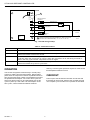
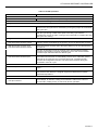
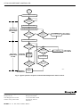
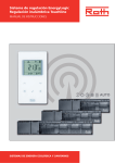
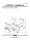
ST74A1053
Defrost Controller
INSTALLATION INSTRUCTIONS
APPLICATION
INSTALLATION
The ST74A is a low voltage time/temperature electronic
defrost controller for heat pumps. This device provides
timed low voltage relay switching to control an external
heat pump defrost relay.
When Installing this Product…
A complete list of the specific Honeywell and other
controllers that the ST74A Defrost Controller is designed
to replace is provided in Tables 1 and 2.
Table 1. OEM Replacement Part Numbers.
Manufacturer
Service Part Number
1. Read these instructions carefully. Failure to follow
them could damage the product or cause a hazardous condition.
2. Check the ratings given in the instructions and on
the product to make sure the product is suitable for
your application.
3. Installer must be a trained, experienced service
technician.
4. After installation is complete, check out product
operation as provided in these instructions.
Amana
C64301-1
C6431001
Artesian
10321-00
Arcoaire
32312-00
Carrier
621
Coleman
3030A374
Mounting
Goodman
B12260-06
Heil Quaker
HQ1052757
Mount the ST74A in the wiring compartment of the outside
section of the heat pump. Use the ST74A as a template to
mark the position of the four mounting eyelets. Use No. 6
or No. 8 sheetmetal screws in the four mounting eyelets.
The control can be mounted in any position, + 45 degrees
to vertical.
ICP
1052757
Intertherm
6208800
Lennox
33G9501
Rheem
47-21776-01
SnyderGeneral
1395-329
Table 2. Controller Manufacturer
Replacement Part Numbers.
Manufacturer
Part Number
Honeywell
ST74A 1004
ST74A 1020
ST74A 1038
White-Rodgers/Steveco
90-621
ICM
300C
Therm-o-Disc
26E-10
Robertshaw
TD-10
®U.S. Registered Trademark
Copyright © 1996 Honeywell Inc. • All Rights Reserved
CAUTION
Disconnect power supply before beginning
installation to prevent electrical shock or equipment
damage.
Wiring
Disconnect power supply to prevent electrical shock or
equipment damage. All wiring must comply with local
codes and ordinances. Refer to Fig. 1 for wiring hookup.
The Off cycle time is determined by a selectable jumper
that allows a choice of 50, 70, or 90 minutes when
connected to T1, T2, or T3, respectively. Select the timing
that is closest to the timing of your original control. If the
timing does not exactly match, choose a longer timing
rather than a shorter one.
See Table 3 for a description of the terminal functions.
X-XX UL
69-0990-1
ST74A1053 DEFROST CONTROLLER
ST74A
TEST
1
T3
T2
RST
T1
DEFROST RELAY
CONTACT
HLD
INDOOR WALL
THERMOSTAT
OUTDOOR COIL
THERMOSTAT
24V
OUT COM
DEFROST
RELAY
1
CONNECT JUMPER LEAD FOR DESIRED OFF TIME AS FOLLOWS
(MINUTES ON STANDARD MODEL): T1 = 50, T2 = 70, T3 = 90.
24 VAC
M7826
Fig. 1. ST74A wiring hookup.
Table 3. Terminal Functions.
Terminals
Function
COM, 24V
Provides power to the ST74A defrost system.
OUT
Provides power to the defrost relay when the control relay contacts are closed and the heat pump
outdoor thermostat contacts are closed.
HLD
Operates the timer. When energized by the indoor thermostat, the timer accumulates defrost Off
cycle time when the compressor is running. When the compressor is off, the timing is held at a
point in the duty cycle until the compressor comes on again.
RST
Returns the timing circuit to the start of the Off cycle when the defrost cycle is interrupted by the
outdoor thermostat or by the On cycle timer.
See Fig. 2 for the typical operation sequence of the ST74A
time/temperature defrost control.
OPERATION
The ST74A energizes the defrost relay in a heat pump
system by relating time and temperature. Defrost takes
place when the compressor reaches a predetermined run
time and the heat pump outdoor coil temperature is below
the predetermined setpoint. The control time-cycles the
heat pump defrost relay On and Off starting with an Off
cycle on power-up. See Table 4 for a description of the
time cycles, coil thermostat and defrost functions.
69-0990—1
CHECKOUT
Power up the ST74A Defrost Controller and set the wall
thermostat to call for heat. Observe the controller through
one complete cycle to make sure it operates as intended.
2
ST74A1053 DEFROST CONTROLLER
Table 4. ST74A Operation.
Process
Function
Power Up
• Wall thermostat contacts closed
With 24 Vac applied, the Off cycle timing starts.
Time Cycle
Off Cycle
• Wall thermostat contacts closed
The defrost control time-cycles when the wall thermostat contacts are
closed. The Off cycle time is selected by moving the jumper to the desired
Off cycle time.
• Wall thermostat contacts open
When the wall thermostat is satisfied, the compressor stops running and
the Off cycle timing is held at this point in the duty cycle until the
compressor comes on again. Timing is then resumed to complete the total
Off cycle time setting.
On Cycle
• Wall thermostat contacts closed
• Coil thermostat contacts closed
Upon completion of the Off cycle time, the defrost relay is pulled-in for ten
minutes unless terminated by the opening of the coil thermostat contacts.
• Wall thermostat contacts open
• Coil thermostat contacts closed
lf the thermostat contacts open during the defrost cycle, the defrost relay
remains in.
On time is held at this point in the duty cycle until the wall thermostat
contacts close again to resume the defrost cycle or the coil thermostat
contacts open and terminate the defrost cycle.
• Wall thermostat contacts closed
• Coil thermostat contacts open
If the coil thermostat contacts open during the defrost cycle, defrost is
terminated and the timer is immediately reset to zero. If the RST (reset)
terminal is not used, the On cycle timer times out. The defrost relay
remains de-energized unless the coil thermostat remakes during the
remainder of the On cycle.
Coil Thermostat
• Contacts open
The system does not go into defrost when the coil thermostat contacts are
open.
• Contacts closed
The coil thermostat contacts close when the heat pump outdoor coil
temperature falls below the Original Equipment Manufacturer (OEM)
selected temperature.
Defrost Test
• Coil thermostat contacts closed
• Test pins shorted
Shorting the TEST pin terminals speeds up the control by a factor of 256;
for example, an Off time setting of 90 minutes is reduced to a time of
21 seconds, making it easy to check out device operation.
3
69-0990—1
ST74A1053 DEFROST CONTROLLER
POWER
UP
SETS ALL TIMERS TO ZERO
WALL
THERMOSTAT
CONTACTS
CLOSED
NO
YES
STARTS OFF-CYCLE TIMER
OFF-CYCLE
TIMING MODE
(SELECTABLE
TIME)
ACCUMULATES OFF-CYCLE TIME
NO
OFF-CYCLE
COMPLETE
WALL
THERMOSTAT
CONTACTS
OPEN
NO
YES
HOLDS
OFF-CYCLE TIMER
OFF-CYCLE
HOLD MODE
YES
STARTS ON-CYCLE TIMER
COIL
THERMOSTAT
CONTACTS
CLOSED
NO
WALL
THERMOSTAT
CONTACTS
CLOSED
YES
ON-CYCLE
TIMING MODE
(10 MIN)
DEFROST
INITIATED
PULLS IN
DEFROST
RELAY
NO
COIL
THERMOSTAT
CONTACTS
OPEN
HOLDS
ON-CYCLE TIMER
ON-CYCLE
HOLD MODE
YES
ACCUMULATES
ON-CYCLE TIME
NO
ON-CYCLE
COMPLETE
YES
DEFROST
TERMINATED
NO
YES
DROPS OUT
DEFROST
RELAY
M7827
Fig. 2. Typical operation sequence of ST74A time/temperature defrost control.
Home and Building Control
Honeywell Inc.
1985 Douglas Drive North
Golden Valley, MN 55422
Home and Building Control
Honeywell Limited
155 Gordon Baker Road
North York, Ontario
M2H 2C9
69-0990—1
69-0990—1 J.S. Rev. 5-96 Printed in Mexico
4