1
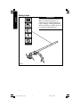
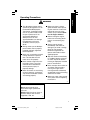
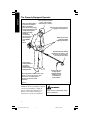
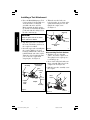
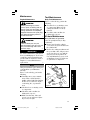
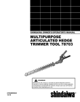
SHINDAIWA OWNER’S/
OPERATOR’S MANUAL
MULTIPURPOSE
TRIMMER TOOL
WARNING!
Always wear eye and
ear protection when
operating this machine!
1439
WARNING!
MT230
To minimize the risk of
injury to yourself and
others, read this manual
and familiarize yourself
with its contents.
1440
1441
65001-94011_MT230_05LP
1
11/6/01, 6:02 AM
Contents
Introduction
PAGE
The Shindaiwa Multipurpose Trimmer
Tool has been designed and built to
deliver superior performance and
reliability without compromise to
quality, comfort, safety or durability.
As an owner/operator, you’ll soon
discover for yourself why Shindaiwa is
simply in a class by itself!
Attention Statements ........................... 2
Safety Labels ........................................ 3
Operating Precautions ........................ 4
General Safety Instructions ................ 6
Product Description ............................ 8
Specifications ....................................... 8
IMPORTANT!
The information contained in these
instructions describes machines
available at the time of publication.
Assembly .............................................. 9
Tool Installation ................................. 11
1442
Shindaiwa Inc. reserves the right to
make changes to products without
prior notice, and without obligation to
make alterations to machines previously manufactured.
Checking Unit Condition .................. 12
Shoulder Strap ................................... 12
Cutting Grass with a Trimmer Head . 13
Edging ................................................. 13
Maintenance ...................................... 14
Troubleshooting Guide .................... 15
1
65001-94011_MT230_05LP
2
11/6/01, 6:02 AM
Attention Statements
WARNING!
A statement preceded by the
triangular attention symbol and the
word “WARNING” contains
information that should be acted
upon to prevent serious bodily
injury.
1177
WEAR EYE AND HEARING
PROTECTION AT ALL TIMES
DURING THE OPERATION
OF THIS UNIT.
KEEP BYSTANDERS
AT LEAST 50 FEET (15 M)
AWAY DURING OPERATION.
BEWARE OF THROWN OR
RICOCHETED OBJECTS.
CAUTION!
A statement preceded by the word
“CAUTION” contains information
that should be acted upon to
prevent mechanical damage.
DO NOT OPERATE THIS
MACHINE WITH A BLADE.
1444
1443
IMPORTANT!
IMPORTANT!
The operational procedures described
A statement preceded by the word
in this manual are intended to help
“IMPORTANT” is one that possesses
you get the most from your machine
special significance.
1179
as well as to protect you and others
from harm. These procedures are
NOTE:
guidelines for safe operation under
A statement preceded by the word
most conditions, and are not intended
“NOTE” contains information that is
handy to know and may make your job to replace any safety rules and/or laws
that may be in force in your area. If
1180
easier.
you have questions regarding your
230-series power tool, or if you do not
understand something in this manual,
your Shindaiwa dealer will be glad to
assist you. You may also contact
Shindaiwa, Inc. at the address printed
on the back of this manual.
1445
2
65001-94011_MT230_05LP
3
11/6/01, 6:02 AM
SAFETY
READ AND FOLLOW THIS
OPERATORS MANUAL.
FAILURE TO DO SO COULD
RESULT IN SERIOUS INJURY.
Throughout this manual are special
“attention statements”.
Safety Labels
SAFETY
IMPORTANT!
Safety and Operation Information Labels:
Make sure all information labels are
undamaged and readable. Immediately
replace damaged or missing information
labels. New labels are available from your
local authorized Shindaiwa dealer.
Figure 1
1446
3
65001-94011_MT230_05LP
4
11/6/01, 6:02 AM
Operating Precautions
SAFETY
WARNING!
■ This Shindaiwa trimmer tool is
specifically designed for use on
the Shindaiwa Multipurpose
Tool Carrier. Installation and/or
use on any other model, brand
or type of power tool is not
approved by Shindaiwa.
Attempts to use on nonapproved models can damage
the equipment and cause
accidents, serious injury or
death.
■ Always make sure the Multipurpose Trimmer Tool is properly
installed and firmly tightened
before operation.
■ Never use a cracked or warped
cutting attachment: replace it
with a serviceable one and
make sure it fits properly.
■ Never smoke or light fires near
the engine. Fuel is very flammable and fire could lead to
serious personal injury or
property damage.
■ Make sure there are no missing
or loose fasteners, and that the
stop switch and throttle controls
are working properly.
■ Make sure there is always
good ventilation when operating this machine. Fumes from
engine exhaust can cause
serious injury or death. Never
run the engine indoors!
■ Before starting the engine,
make sure the cutting attachment is not contacting anything.
■ Always stop the engine
immediately and check for
damage if you strike a foreign
object or if the machine
becomes tangled. Do not
operate with broken or damaged equipment.
■ Stop the machine immediately
if it suddenly begins to vibrate
or shake. Inspect for broken,
missing or improperly installed
parts or attachments.
■ Never transport the machine or
set it down with the engine
running. An engine that’s
running could be accidentally
accelerated causing the cutting
attachment to rotate.
■ Make sure cutter safety guards
are in place when transporting
the machine.
1448
CAUTION!
Never extend trimming line
beyond the length specified for
your unit.
Always keep the unit as clean as
practical. Keep it free of loose
vegetation, mud, etc.
1447
4
65001-94011_MT230_05LP
5
11/6/01, 6:02 AM
SAFETY
The Properly Equipped Operator
Wear close-fitting clothing
to protect legs and arms.
Gloves offer added
protection and are strongly
recommended. Do not wear
clothing or jewelry that
could get caught in
machinery
or underbrush.
Secure hair so it is
above shoulder
level. NEVER
wear
shorts!
Wear hearing protection
devices and a broadbrimmed hat or helmet.
Always wear eye protection such
as goggles or safety glasses.
Always operate with
both hands firmly
gripping the machine.
Keep away from the rotating
trimmer line at all times, and
never lift a moving attachment above waist-high.
Keep a proper
footing and do not
overreach—
maintain your
balance at all times
during operation.
Wear appropriate footwear (non-skid
boots or shoes): do not wear opentoed shoes or sandals. Never
operate the machine while
barefoot!
Always make sure
the appropriate
cutting attachment
shield is correctly
installed and in
good condition.
Figure 2
1449
Work Safely
Trimmers run at very high speeds and
can do serious damage or injury if
they are misused or abused. Never
allow a person without training or
instruction to operate your machine!
WARNING!
Never make unauthorized attachment installations.
1450
5
65001-94011_MT230_05LP
6
11/6/01, 6:02 AM
General Safety Instructions
SAFETY
DO NOT OPERATE THIS UNIT
IF YOU ARE TIRED, ILL OR
UNDER THE INFLUENCE OF
ALCOHOL, DRUGS, OR
MEDICATION.
WARNING! Minimize the Risk of Fire
Never smoke or light fires near the trimmer.
Always stop the engine and allow it to cool before refueling. Avoid
overfilling and wipe off any fuel that may have spilled.
Always move the unit to a place well away from a fuel storage area or
other readily flammable materials before starting the engine. Use caution
when handling fuel. Move the power tool at least 10 feet (3 meters) from
the fueling point before starting the engine.
Never place flammable material close to the engine muffler.
Never run the engine without the spark arrester screen in place. Do not
operate the machine with the muffler removed.
1452
WARNING!
Use Good Judgment
Always wear eye protection to
shield against thrown objects.
Always protect yourself from
hazards such as thorny brush and
flying debris by wearing gloves
and close fitting clothing that
covers arms and legs. Never wear
shorts. Don’t wear loose clothing
or items such as jewelry that could
get caught in machinery or
underbrush. Secure long hair so it
is above shoulder level.
Never run the engine indoors!
Make sure there is always good
ventilation. Fumes from engine
exhaust can cause serious injury
or death.
Always clear your work area of
trash or hidden debris that could
be thrown back at you or toward a
bystander.
Always use the proper cutting tool
for the job.
Always stop the machine immediately if it suddenly begins to
vibrate or shake. Inspect for
broken, missing or improperly
installed parts or attachments.
Always hold the machine firmly
with both hands when cutting or
trimming, and maintain control at
all times.
Always keep the handles clean.
Always disconnect the spark plug
wire before performing any
maintenance work.
1453
6
65001-94011_MT230_05LP
7
11/6/01, 6:02 AM
SAFETY
Be Aware of the Working Environment
Make sure bystanders or
observers outside the 50-foot
“danger zone” wear eye
protection.
Avoid long-term
operation in very hot
or very cold weather.
Reduce the risk of
bystanders being
struck by flying debris.
Make sure no one is
within 50 feet
(15 meters)—that’s
about 16 paces—of an
operating attachment.
Be extremely
careful of
slippery terrain,
especially
during rainy
weather.
Always make sure
the appropriate
cutting attachment
shield is correctly
installed.
If contact is made with a hard object, stop
the engine and inspect the cutting
attachment for damage.
Be constantly alert for objects and debris that
could be thrown either from the rotating cutting
attachment or bounced from a hard surface.
When operating in rocky terrain
or near electric wires or fences,
use extreme caution to avoid
contacting such items with the
cutting attachment.
Figure 3
1454
7
65001-94011_MT230_05LP
8
11/6/01, 6:02 AM
Product Description and Specifications
Multipurpose
Trimmer Tool
Outer Tube
DESCRIPTION
Gearcase
Cutting
Attachment
Shield
Figure 4
Trimmer
Head
1455
Using the accompanying illustrations
as a guide, familiarize yourself with
your machine and its various components. Understanding your machine
helps ensure top performance, long
service life, and safer operation.
See Figure 4.
WARNING!
Do not make unauthorized
modifications or alterations to any
of these units or their components.
1456
Multipurpose Trimmer Tool Specifications
Multipurpose Trimmer Tool (less cutting attachment) ................ 2.5 lbs. (1.2 kg)
Gearcase Lubrication ............................. Lithium based grease (Shindaiwa 13-57)
Gear Reduction ................................................................................................ 1.286:1
Gearcase Arbor Size .............................................. 7mm Left-hand thread (female)
*Specifications are subject to change without notice.
Prior to Assembly
Before assembling, make sure you
have all the components required for a
complete unit:
Carefully inspect all components for
damage.
IMPORTANT!
■ Outer Tube/Main Shaft Assembly
The terms “left”, “left-hand”, and “LH”;
“right”, “right-hand”, and “RH”; “front”
and “rear” refer to directions as
viewed by the operator during normal
operation.
■ Cutting Attachment Shield
■ Trimmer Head
■ Kit containing cutting attachment
shield mounting bracket and
hardware, gearcase tool holder,
this owner's/operator's manual and
a hex wrench.
1457
8
65001-94011_MT230_05LP
9
11/6/01, 6:02 AM
Assembly
Cutting Attachment Shield
SocketHead
Cap
Screw
Outer
Tube
Cutting
Attachment
Shield
Bracket
ASSEMBLY
Shim
Clamp
Screw
Shim
1025
Retaining
Nut
Cutting Attachment
Shield Mounting Plate
Figure 5
1323
Install the Cutting Attachment Shield.
1. Insert the cutting attachment
shield between the outer tube and
the cutting attachment mounting
plate. See Figure 5.
NOTE:
3. Tighten the four socket-head cap
screws to secure the cutting
attachment shield.
WARNING!
It may be necessary to loosen the
retaining nut and clamp screw to
adjust cutting attachment shield
mounting plate.
NEVER operate the M230 trimmer
without the cutting attachment
shield installed and tightly secured!
1211
2. Fit the two shims and the bracket
over the outer tube and loosely
install the four socket-head screws.
See Figure 5.
CAUTION!
Make sure the clamp screw and
retaining nut is securely tightened
before tightening the four socket
head screws.
1210
9
65001-94011_MT230_05LP
10
11/6/01, 6:02 AM
Assembly
Trimmer Head
Model MT230
Holder
Output
Shaft
ASSEMBLY
Position the Tool holder
Install the trimmer head
Figure 6
1458
Figure 7
1459
Install the Trimmer Head.
1. Turn the trimmer over so that the
gearcase output shaft faces UP.
See Figure 6.
2. Remove and discard the plastic
retaining plug.
3. Position the tool holder as shown,
and slide the holder onto the output
shaft. See Figure 6.
4. Rotate the tool holder and shaft
until the notch in the holder aligns
with the notch on the gearcase
flange, and use the long end of the
hex wrench to lock the output shaft
in position. See Figure 7.
5. While holding the hex wrench,
thread the trimmer head onto the
output shaft, turning counterclockwise.
6. Using hand pressure only, tighten
the trimmer head firmly on the
gearshaft. See Figure 7.
IMPORTANT!
The trimmer head has a left-hand
thread. Turn the trimmer head
counter-clockwise to install.
1460
7. Remove the hex wrench.
WARNING!
A standard T-series machine
should NEVER be operated with
blade-type attachments.
1461
The Multipurpose Trimmer Tool should now be
completely assembled and ready for use.
10
65001-94011_MT230_05LP
11
11/6/01, 6:02 AM
Installing a Tool Attachment
1. Place the M230 Multipurpose Tool 4. When the two tube halves are
Carrier and the Tool Assembly on a
locked together, press down on the
clean, flat surface so that both
spring-loaded latch protector and
assemblies fit end to end. The
tighten the coupler screw.
M230 assembly should be facing
See Figure 9.
up, and the tool assembly should be
Coupler
positioned with the locking hole in
Latch Protector
the tube end facing up.
(lowered)
ASSEMBLY
CAUTION!
Keep the open ends of the tubes
clean and free of debris!
1462
M23005
2. Slip off the protective covers from
the ends of both tubes, and loosen
the coupler screw knob.
3. Insert the upper tube assembly into
the coupler, with the tool decal
facing up, until the line of the decal
is flush with the end of the coupler.
Twist the tool back and forth until
you are sure the coupler latch
snaps in place. See Figure 8.
M230 Tube
Assembly
Coupler Screw
Knob
Figure 9
1464
Disassembling The Pole Sections
1. With the pole on a clean, flat
surface, loosen the coupler screw.
The spring-loaded coupler protector should pop up.
2. Press down on the latch with your
finger or thumb. This releases the
coupler lock. See Figure 10.
Latch Protector
(extended)
3. Pull the lower tube assembly out of
the coupler.
Latch
Locking
Hole
Press
Latch
M23004
Coupler
Screw
Knob
Coupler
Tool
Assembly
Figure 8
1463
M23006
Figure 10
1465
11
65001-94011_MT230_05LP
12
11/6/01, 6:02 AM
Checking Unit Condition
NOTE:
NEVER operate the unit with the
cutting attachment shield or other
protective devices (ignition switch,
etc.) removed!
Although a shoulder strap accessory is
not required for use with a Multipurpose Trimmer Tool, a shoulder strap
can increase operator comfort during
extended periods of operation.
1466
See Figure 11.
WARNING!
A cutting attachment shield or
other protective device is no
guarantee of protection against
ricochet. YOU MUST ALWAYS
GUARD AGAINST FLYING
DEBRIS!
Shoulder Strap
Shoulder strap
is available for
use
with the
Multipurpose
Trimmer Tool.
1465
Use only authorized Shindaiwa parts
and accessories with your Shindaiwa
trimmer. Do not make modifications
to your machine without the written
approval of Shindaiwa, Inc.
Figure 11
1467
NEVER use a cracked or warped
cutting attachment: replace it with a
serviceable one.
ALWAYS make sure the cutting
attachment fits properly into the
appropriate cutter holder. If a properly installed attachment vibrates,
replace the attachment with new one
and re-check.
ALWAYS stop the engine immediately and check for damage if you
strike a foreign object or if the
machine becomes tangled. Do not
operate with broken or damaged
equipment.
NEVER allow the engine to run at
high RPM without a load. Doing so
could damage the engine.
NEVER operate a machine with worn
or damaged fasteners or attachment
holders.
12
65001-94011_MT230_05LP
13
11/6/01, 6:02 AM
OPERATION
ALWAYS make sure the cutting
attachment is properly installed and
firmly tightened before operation.
Cutting Grass
Your Shindaiwa Multipurpose Trimmer Tool may be equipped with one of
several Shindaiwa trimmer head
models, each with features for specific
applications and/or operational
requirements.
Trimming and Mowing Grass
NOTE:
For proper operation, always refer to
the instructions accompanying the
trimmer head being used. Available
1468
trimmer head styles include:
■ Semi-automatic. Trimmer line is
indexed when the operator taps the
trimmer head on the ground during
operation.
OPERATION
■ Manual. The operator indexes line
manually with the grass trimmer
stopped.
■ Fixed. The operator must stop the
machine and add new lengths of
trimmer line manually.
■ Flail. This device, designed for
clearing weeds and light brush,
features three pivoting nylon
blades.
Figure 12
1344
Hold the grass trimmer so the
trimmer head is angled slightly into
the area to be cut. To ensure maximum trimmer-line service life, cut only
with the tip of the trimmer line. Cut
grass by swinging the machine’s
trimmer head from right to left. Keep
the trimmer head
horizontal. See Figure 12.
Edging
CAUTION!
Do not push the rotating trimmer
line into trees, wire fences or any
other solid objects that could
tangle or break line ends.
1469
Tilt the handle
about 100° to
the left (from
horizontal) and
move forward,
holding the
trimmer
vertically.
See Figure 13.
Engine Operating Speeds
Operate the machine at full throttle
while cutting grass.
CAUTION!
Operation at low RPM can lead to
premature clutch failure.
1490
Figure 13
13
65001-94011_MT230_05LP
14
11/6/01, 6:02 AM
1345
Maintenance
Tool Maintenance
Engine Maintenance
Daily Tool Maintenance
Prior to each work day, perform the
following:
WARNING!
Before performing any maintenance, repair, or cleaning work on
the unit, make sure the engine and
cutting attachment are completely
stopped. Disconnect the spark plug
wire before performing service or
maintenance work.
1491
WARNING!
Non-standard parts may not
operate properly with your unit and
may cause damage and lead to
personal injury.
1492
IMPORTANT!
For detailed maintenance information
about your Multipurpose Tool Carrier,
consult the owner's manual that was
provided with it. If it has been lost or
misplaced, contact Shindaiwa for a
replacement.
1493
■ Check for loose or missing screws
or components. Make sure the
cutting attachment is securely
fastened.
■ Check the entire machine for
leaking fuel or grease.
50-hour Maintenance
Every 50 hours of operation
(more frequently in dusty or dirty
conditions):
■ Remove and clean the cylinder
cover and clean grass and dirt from
the cylinder fins.
■ Remove the cutting attachment and
the gear shaft collar, and press new
grease into the gear case until the
old grease has been pushed out.
Use only lithium-base grease such
as Shindaiwa Gear Case Lubricant
or equivalent. See Figure 14.
NOTE:
Using non-standard replacement parts
could invalidate your Shindaiwa
1494
warranty.
■ Carefully remove any accumulations of dirt or debris from the
muffler and fuel tank. Dirt build-up
in these areas can lead to engine
overheating, fire, or premature
wear.
New
Grease
MAINTENANCE
Prior to each work day, perform the
following:
Old
Grease
Gear
Shaft
Collar
Figure 14
1495
■ Check for loose or missing screws
or components.
■ Check the entire machine for
leaking fuel or grease.
■ Make sure that nuts, bolts, and
screws (except carburetor adjusting screws) are tight.
14
65001-94011_MT230_05LP
15
11/6/01, 6:02 AM
Troubleshooting Guide
ADDITIONAL PROBLEMS
Symptom
Excessive
vibration.
Cutter will not
rotate.
TROUBLESHOOTING
Cutting attachment
rotates at engine
idle.
Possible Cause
Remedy
Warped or damaged
attachment.
Inspect and replace
attachment as required.
Loose gearcase.
Tighten gearcase securely.
Bent main shaft/worn or
damaged bushings.
Inspect and replace
as necessary.
Shaft not installed
in coupler or
gearcase.
Inspect and reinstall
as required.
Broken shaft.
Consult with an authorized
servicing dealer.
Damaged gearcase.
Consult with an authorized
servicing dealer.
Engine idle too high.
Adjust engine idle speed
2,750 RPM. (Ⳳ250 )
Broken clutch spring
or worn clutch spring
boss.
Replace clutch spring
and shoes as required.
15
65001-94011_MT230_05LP
16
11/6/01, 6:02 AM
NOTES
16
65001-94011_MT230_05LP
17
11/6/01, 6:02 AM
Shindaiwa Inc.
P.O. Box 2810
Tualatin, Oregon 97062
Telephone: 503 692-3070
FAX:
503 692-6696
www.shindaiwa.com
Shin-Daiwa Kogyo Co., Ltd.
Head Office: 6-2-11 Ozuka
Nishi, Asaminami-ku
Hiroshima, 731-3167, Japan
Telephone: 81-82-849-2220
FAX:
81-82-849-2481
䊚2001 Shindaiwa, Inc.
Part Number 65001-94011
Printed in Japan
Rev. 10/01
Shindaiwa Tornado is a trademark,
and Shindaiwa is a registered trademark
of Shindaiwa, Inc.
Specifications subject to change without notice.
65001-94011_MT230_05LP
18
11/6/01, 6:02 AM