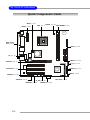
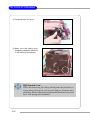
1
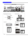
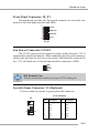
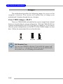
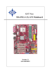
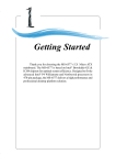
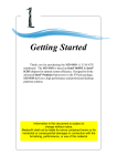
Getting Started
Chapter 1. Getting
Started
Getting Started
Thank you for purchasing the MS-7010 v1.X Micro ATX
mainboard. The MS-7010 is based on VIA® K8T800 North
Bridge & VT8237 South Bridge and provides eight USB 2.0
ports for high-speed data transmission, C-Media 9761 audio
codec for 6-channel audio output, and a SPDIF interface for
digital audio transmission. Designed to fit the advanced AMD®
Athlon64 processors, the MS-7010 delivers a high performance
and professional desktop platform solution.
1-1
MS-7010 M-ATX Mainboard
Mainboard Specifications
CPU
h Supports 64-bit AMD® Athlon64 processor (Socket 754)
h Supports up to 3200+, 3400+, or higher CPU
Chipset
h VIA® K8T800 chipset
- HyperTransportTM connection to AMD Athlon64 processor
- 8 or 16 bit control/address/data transfer both directions
- 800/600/400/200 MHz “Double Data Rate” operation both direction
- AGP v3.0 compliant with 8x transfer mode
h VIA® VT8237 chipset
- Integrated Faster Ethernet LPC
- Integrated Hardware Sound Blaster/Direct Sound AC97 audio
- Ultra DMA 66/100/133 master mode PCI EIDE controller
- ACPI
- Supports 2 Serial ATA ports
- Supports 8 USB2.0 ports
Main Memory
h Supports DDR266/333/400 DDR SDRAM for two 184-pin DDR DIMMs
h Supports a maximum memory size of 2GB
Slots
h One (Accelerated Graphics Port) AGP slot
- AGP 3.0 specification compliant (1.5V for 2X/4X/8X)
h Three 32-bit Master 3.3v/5v PCI Bus slots
h One mini PCI slot
On-Board IDE
h An IDE controller on the VIA® VT8237 chipset provides IDE HDD/CDROM with PIO, Bus Master and Ultra DMA 66/100/133 operation modes
h Can connect up to 4 IDE devices
h Serial ATA/150 controller integrated by VT8237
- Up ot 150MB/s transfer rate
- Can connect up to 2 serial ATA devices
1-2
Getting Started
IEEE 1394 (Optional)
h Supports up to 2 * 1394 ports (up to 400Mbps transfer rate)
h Controlled by VIA VT6307 chipset
On-Board Peripherals
h On-Board Peripherals include:
- 1 floppy port supports 2 FDDs with 360K, 720K, 1.2M, 1.44M and
2.88Mbytes
- 1 serial port (COMA)
- 1 parallel port supports SPP/EPP/ECP mode
- 8 USB ports (Rear * 4/Front * 4)
- 2 IEEE 1394 ports (Rear * 1/Front * 1)
- 1 audio port
- 1 RJ-45 LAN jack
Audio
h C-Media 9761 6-channel software audio codec
- Compliance with AC97 v2.3 Spec
- Meet PC2001 audio performance requirement
LAN
h VIA® VT6103 Ethernet Controller
- Integrated Fast Ethernet MAC and PHY in one chip
- Supports 10Mbps & 100Mbps
BIOS
h The mainboard BIOS provides “Plug & Play” BIOS which detects the peripheral devices and expansion cards of the board automatically.
h The mainboard provides a Desktop Management Interface (DMI) function
which records your mainboard specifications.
Dimension
h Micro ATX Form Factor: 24.5 cm (L) x 24.5 cm (W)
Mounting
h 6 mounting holes
1-3
MS-7010 M-ATX Mainboard
Mainboard Layout
Top: Mouse
Bottom: Keyboard
BATT
+
JWR1
CFAN1
Top: LAN Jack
Bottom: USB Ports
FDD1
IDE 1
VIA
K8T800
VIA
K8T800
PCI Slot 1
Codec
DDR 2
DDR 1
AGP Slot
VIA
VT6103
VIA
VT6307
VIA
VT8237
PCI Slot 3
MINIPCI1
JUSB1
SATA1
JUSB2
JF_W1
MS-7010 v1.X Micro ATX Mainboard
1-4
JF_P1
SATA2
PCI Slot 2
JAUDIO2 JAUDIO1
JVIDEO1
IDE 2
JPW1
Top: 1394 Port
Bottom: USB Ports
Winbond
83697THF
T: Line-O ut
J3
M: Line-O ut
B: Line-O ut
T: Mic
B: Line-In
BIOS
JBAT1
Hardware Setup
Chapter 2. Hardware
Setup
Hardware Setup
This chapter tells you how to install the CPU, memory
modules, and expansion cards, as well as how to setup the jumpers on the mainboard. Also, it provides the instructions on connecting the peripheral devices, such as the mouse, keyboard,
etc.
While doing the installation, be careful in holding the components and follow the installation procedures.
2-1
MS-7010 M-ATX Mainboard
Quick Components Guide
JPW1, p.2-11
CPU, p.2-3
CFAN1, p.2-15
JWR1, p.2-11
DDR DIMMs, p.2-9
BATT
+
Back Panel
I/O, p.2-12
FDD1, p.2-13
J3, p.2-15
BIOS
IDE1/2, p.2-13
AGP Slot, p.2-19
JF_P1, p.2-15
VIA
VT8237
PCI Slots,p.2-19
JBAT1, p.2-19
JVIDEO1, p.2-14
JAUDIO2, p.2-14
JF_W1,p.2-16
JAUDIO1, p.2-14
JUSB1/2, p.2-16
2-2
SATA1/2,p.2-17
Mini PCI, p.2-19
Hardware Setup
Central Processing Unit: CPU
The mainboard supports AMD® Athlon64 processor. The mainboard
uses a CPU socket called Socket-754 for easy CPU installation. When you are
installing the CPU, make sure the CPU has a heat sink and a cooling fan
attached on the top to prevent overheating. If you do not have the heat sink
and cooling fan, contact your dealer to purchase and install them before turning on the computer.
MSI Reminds You...
Overheating
Overheating will seriously damage the CPU and system, always
make sure the cooling fan can work properly to protect the CPU
from overheating.
Replacing the CPU
While replacing the CPU, always turn off the ATX power supply
or unplug the power supply’s power cord from grounded outlet
first to ensure the safety of CPU.
2-3
MS-7010 M-ATX Mainboard
CPU Installation Procedures for Socket 754
1. Please turn off the power and
unplug the power cord before
installing the CPU.
2. Pull the lever sideways away
from the socket. Make sure
to raise the lever up to a 90degree angle.
3. Look for the gold arrow. The
gold arrow should point towards the lever pivot. The
CPU can only fit in the correct orientation.
4. If the CPU is correctly
installed, the pins should be
completely embedded into the
socket and can not be seen.
Please note that any violation
of the correct installation procedures may cause permanent
damages to your mainboard.
O pen Lever
Sliding
Plate
90 degree
G old arrow
C orrect C PU placem ent
G old arrow
O
IncorrectC PU placem ent
5. Press the CPU down firmly
into the socket and close the
lever. As the CPU is likely to
move while the lever is being
closed, always close the lever
with your fingers pressing
tightly on top of the CPU to
make sure the CPU is properly and completely embedded into the socket.
2-4
G old arrow
Press dow n
the C PU
X
C lose
Lever
Hardware Setup
Installing AMD Athlon64 CPU Cooler Set
When you are installing the CPU, make sure the CPU has a heat sink
and a cooling fan attached on the top to prevent overheating. If you do not
have the heat sink and cooling fan, contact your dealer to purchase and install
them before turning on the computer.
1. Detach the shield of the
backplate’s paster.
2. Turn over the mainboard, and
install the backplate to the
proper position.
2-5
MS-7010 M-ATX Mainboard
3. Turn over the mainboard
again, and place the
mainboard on the flat surface.
Locate the two screw holes of
the mainboard.
4. Align the retention mechanism
and the backplate.
Fix the retention mechanism
and the backplate with two
screws.
retention mechanism
5. Position the cooling set onto
the retention mechanism.
Hook one end of the clip to
hook first.
2-6
Hardware Setup
6. Press down the other end of
the clip to fasten the cooling set
on the top of the retention
mechanism.
7. Locate the Fix Lever, Saftey
Hook and the Fixed Bolt.
Lift up the intensive fixed lever.
Safety Hook
Fixed Lever
Fixed Bolt
MSI Reminds You...
Mainboard photos shown in this section are for demonstration
of the installation of AMD Athlon 64 CPU Cooler Set only. The
appearance of your mainboard may vary depending on the
model you purchase.
2-7
MS-7010 M-ATX Mainboard
8. Fastened down the lever.
9. Make sure the safety hook
completely clasps the fixed bolt
of the retention mechanism.
MSI Reminds You...
While disconnecting the Safety Hook from the fixed bolt, it
is necessary to keep an eye on your fingers, because once
the Safety Hook is disconnected from the fixed bolt, the fixed
lever will spring back instantly.
2-8
Hardware Setup
Memory
The mainboard provides 2 slots for 184-pin DDR SDRAM DIMM
(Double In-Line Memory Module) modules and supports the memory size up
to 2GB. You can install PC3200/DDR400, PC2700/DDR333, PC2100/
DDR266 or PC1600/DDR200 unbuffered DIMM modules on the DDR DIMM
slots (DDR 1~2).
DDR DIMM Slots
(DDR 1~2)
*Please Refer to <www.msi.com.tw>
for the latest qualified memory list to
ensure the system stability.
Introduction to DDR SDRAM
DDR (Double Data Rate) SDRAM is similar to conventional SDRAM,
but doubles the rate by transferring data twice per cycle. It uses 2.5 volts as
opposed to 3.3 volts used in SDR SDRAM, and requires 184-pin DIMM modules rather than 168-pin DIMM modules used by SDR SDRAM. High memory
bandwidth makes DDR an ideal solution for high performance PC, workstations and servers.
2-9
MS-7010 M-ATX Mainboard
DDR DIMM Population Rules
Install at least one DIMM module on the slots. Memory modules can be
installed on the slots in any order. You can install either single- or doublesided modules to meet your own needs.
Memory modules can be installed in any combination as follows:
Slot
DIMM 1 (Bank 0 & 1)
DIMM 2 (Bank 2 & 3)
Memory Module
S/D
S/D
Maximum System Memory Supported
S: Single Side
64MB~2GB
D: Double Side
Installing DDR Modules
1. The DDR DIMM has only one notch on the center of module. The module will only fit in the right orientation.
2. Insert the DIMM memory module vertically into the DIMM slot. Then
push it in until the golden finger of the memory module is deeply inserted
in the socket.
MSI Reminds You...
You can barely see the golden finger if the module is properly
inserted in the socket.
3. The plastic clip at each side of the DIMM slot will automatically close.
Volt
2-10
Notch
Hardware Setup
Power Supply
The mainboard supports ATX power supply for the power system. Before inserting the power supply connector, always make sure that all components are installed properly to ensure that no damage will be caused.
ATX 20-Pin Power Connector: JWR1
This connector allows you to connect to an ATX power supply. To
connect to the ATX power supply, make sure the plug of the power supply is
inserted in the proper orientation and the pins are aligned. Then push down
the power supply firmly into the connector.
1
11
JWR1 Pin Definition
10
20
JWR1
PIN
SIGNAL
PIN
SIGNAL
1
2
3
4
5
6
7
8
9
3.3V
3.3V
GND
5V
GND
5V
GND
PW_OK
5V_SB
10
12V
11
12
13
14
15
16
17
18
19
20
3.3V
-12V
GND
PS_ON
GND
GND
GND
-5V
5V
5V
ATX 12V Power Connector: JPW1
This 12V power connector is used to provide power to the CPU.
JPW1 Pin Definition
4
3
JPW1
2
PIN
SIGNAL
1
1
2
3
4
GND
GND
12V
12V
MSI Reminds You...
Power supply of 300 (and up) watt is highly recommended for system stability.
2-11
MS-7010 M-ATX Mainboard
Back Panel
L-Out
Parallel
Mouse
LAN
IEEE 1394
Mic-In
Keyboard
COM A
SPDIF Out SPDIF In
RJ-45 LAN Jack
Mouse/Keyboard Connector
Pin5
Mouse/KBD
Clock
Pin6 NC
Pin4 VCC
8
Pin3 GND
PIN
1
2
3
4
Pin1
Mouse/KBD
DATA
Pin2 NC
Serial Port
SIGNAL
TDP
TDN
RDP
NC
1
PIN
5
6
7
8
SIGNAL
NC
RDN
NC
NC
IEEE 1394 Port
1
2
6
2-12
L-Out L-In
L-Out
USB Ports
3
7
4
8
5
2
4
6
1
3
5
9
PIN
SIGNAL
1
2
3
4
5
6
7
8
9
DCD
SIN
SOUT
DTR
GND
DSR
RTS
CTS
RI
PIN
SIGNAL
1
2
3
4
5
6
PWR
GND
TPBTPB+
TPATPA+
USB Ports
1
2
3
4
PIN
1
2
3
4
SIGNAL
VCC
-Data
+Data
GND
Hardware Setup
Connectors
The mainboard provides connectors to connect to FDD, IDE HDD, case,
modem, LAN, USB ports, and CPU/system fans.
Floppy Disk Drive Connector: FDD1
The mainboard provides a standard floppy disk drive connector that
supports 360K, 720K, 1.2M, 1.44M and 2.88M floppy disk types.
Hard Disk Connectors: IDE1 & IDE2
The mainboard has a 32-bit Enhanced PCI IDE and Ultra DMA 33/66/
100/133 controller that provides PIO mode 0~4, Bus Master, and Ultra
DMA33/66/100/133 function. You can connect up to four hard disk drives,
CD-ROM, 120MB Floppy (reserved for future BIOS) and other devices. These
connectors support the provided IDE hard disk cable.
FDD1
IDE1 IDE2
IDE1 (Primary IDE Connector)
The first hard drive should always be connected to IDE1. IDE1 can
connect a Master and a Slave drive. You must configure second hard
drive to Slave mode by setting the jumper accordingly.
IDE2 (Secondary IDE Connector)
IDE2 can also connect a Master and a Slave drive.
MSI Reminds You...
If you install two hard disks on cable, you must configure the
second drive to Slave mode by setting its jumper. Refer to the
hard disk documentation supplied by hard disk vendors for
jumper setting instructions.
2-13
MS-7010 M-ATX Mainboard
CD-In Connector: JAUDIO2
The connector is for CD-ROM audio connector.
Audio Connector: JVIDEO1
This connector allows you to connect to a TV Tuner Card.
JAUDIO2
R GND L
JVIDEO1
VIDEO-R
G VIDEO-L
N
D
Front Panel Audio Connector: JAUDIO1
The JAUDIO1 front panel audio connector allows you to connect to the
front panel audio and is compliant with Intel® Front Panel I/O Connectivity
Design Guide.
JAUDIO1
9
10
1
2
Pin Definition
PIN
SIGNAL
DESCRIPTION
1
2
3
4
5
6
7
8
9
10
AUD_MIC
AUD_GND
AUD_MIC_BIAS
AUD_VCC
AUD_FPOUT_R
AUD_RET_R
HP_ON
KEY
AUD_FPOUT_L
AUD_RET_L
Front panel microphone input signal
Ground used by analog audio circuits
Microphone power
Filtered +5V used by analog audio circuits
Right channel audio signal to front panel
Right channel audio signal return from front panel
Reserved for future use to control headphone amplifier
No pin
Left channel audio signal to front panel
Left channel audio signal return from front panel
MSI Reminds You...
If you don’t want to connect to the front audio
header, pins 5 & 6, 9 & 10 have to be jumpered
in order to have signal output directed to the
rear audio ports. Otherwise, the Line-Out connector on the back panel will not function.
2-14
9
10
1
2
Hardware Setup
Front Panel Connector: JF_P1
The mainboard provides one front panel connector for electrical connection to the front panel switches and LEDs.
1
PS-ON
PWR_LED
HDD_LED
Reset
8
JF_P1
Fan Power Connector: CFAN1
The CFAN1 (processor fan) supports system cooling fan with +12V. It
supports three-pin head connector. When connecting the wire to the connector,
always take note that the red wire is the positive and should be connected to
the +12V, the black wire is Ground and should be connected to GND.
GND
+12V
Sensor
CFAN1
MSI Reminds You...
Always consult the vendors for proper CPU cooling fan.
Joystick/Game Connector: J3 (Optional)
You can connect a joystick or game pad to this connector.
J3 Pin Definition
J3
1
11
2
12
Pin
Description
Pin
Description
1
FVCC5 (power)
2
Key pin
3
RXD
4
GP4
5
GP5
6
GP6
7
GP7
8
GP2
9
GP1
10
GP0
11
GP3
12
TXD
2-15
MS-7010 M-ATX Mainboard
IEEE 1394 Connector: JF_W1
The mainboard provides one IEEE1394 pin header that allows you to
connect IEEE 1394 ports via an external IEEE1394 bracket.
Pin Definition
1
2
9
10
JF_W1
PIN
SIGNAL
PIN
1
TPA+
2
SIGNAL
TPA-
3
Ground
4
Ground
5
TPB+
6
TPB-
7
Cable power
8
Cable power
9
Key (no pin)
10
Ground
Front USB Connectors: JUSB1/JUSB2
The mainboard provides two USB 2.0 pin headers JUSB1 & JUSB2 that
are compliant with Intel® I/O Connectivity Design Guide. USB 2.0 technology increases data transfer rate up to a maximum throughput of 480Mbps,
which is 40 times faster than USB 1.1, and is ideal for connecting high-speed
USB interface peripherals such as USB HDD, digital cameras, MP3 players,
printers, modems and the like.
Pin Definition
9
10
1
2
JUSB1/2
2-16
PIN
SIGNAL
PIN
SIGNAL
1
USBPWR
2
USBPWR
3
USBP4-
4
USBP5-
5
USBP4+
6
USBP5+
7
GND
8
GND
9
NC
10
USBOC
Hardware Setup
Serial ATA HDD Connectors: SATA1, SATA2
The mainboard provides dual high-speed Serial ATA interface ports.
The ports support 1st generation Serial ATA data rates of 150MB/s and are
fully compliant with Serial ATA 1.0 specifications. Each Serial ATA connector can connect to 1 hard disk drive.
SATA2
1
Pin Definition
PIN
SIGNAL
PIN
SIGNAL
7
1
GND
2
TXP
1
3
5
7
TXN
RXN
GND
4
6
GND
RXP
7
SATA1
Take out the dust cover and
connect to the hard disk devices
Optional Serial ATA cable
Connect to SATA1 or SATA2
MSI Reminds You...
Please do not fold the Serial ATA cable into 90-degree angle.
Otherwise, the loss of data may occur during transmission.
2-17
MS-7010 M-ATX Mainboard
Jumper
The motherboard provides the following jumper for you to set the
computer’s function. This section will explain how to change your
motherboard’s function through the use of jumper.
Clear CMOS Jumper: JBAT1
There is a CMOS RAM on board that has a power supply from external
battery to keep the data of system configuration. With the CMOS RAM, the
system can automatically boot OS every time it is turned on. If you want to
clear the system configuration, use the JBAT1 (Clear CMOS Jumper ) to clear
data. Follow the instructions below to clear the data:
1
JBAT1
1
1
3
3
Keep Data
Clear Data
MSI Reminds You...
You can clear CMOS by shorting 2-3 pin while the system is off.
Then return to 1-2 pin position. Avoid clearing the CMOS while
the system is on; it will damage the mainboard.
2-18
Hardware Setup
Slots
The motherboard provides one AGP slot, one mini PCI slot, and three
32-bit PCI bus slots.
AGP (Accelerated Graphics Port) Slot
The AGP slot allows you to insert the AGP graphics card. AGP is an
interface specification designed for the throughput demands of 3D graphics.
It introduces a 66MHz, 32-bit channel for the graphics controller to directly
access main memory. The onboard AGP slot supports up to 8X AGP card.
PCI (Peripheral Component Interconnect) Slots
The PCI slots allow you to insert the expansion cards to meet your needs.
When adding or removing expansion cards, make sure that you unplug the
power supply first. Meanwhile, read the documentation for the expansion card
to make any necessary hardware or software settings for the expansion card,
such as jumpers, switches or BIOS configuration. The second PCI slot (in
BLUE color) supports 2 master devices.
PCI Interrupt Request Routing
The IRQ, acronym of interrupt request line and pronounced I-R-Q, are
hardware lines over which devices can send interrupt signals to the
microprocessor. The PCI IRQ pins are typically connected to the PCI bus INT
A# ~ INT D# pins as follows:
Order 1
Order 2
Order 3
Order 4
PCI Slot 1
INT A#
INT B#
INT C#
INT D#
PCI Slot 2
INT B#
INT C#
INT D#
INT A#
PCI Slot 3
INT C#
INT D#
INT A#
INT B#
2-19