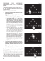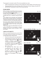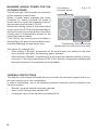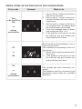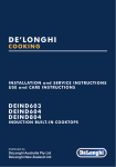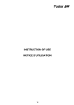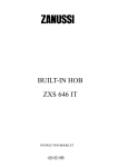
1
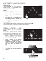
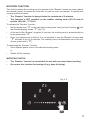
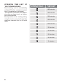
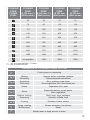
Instructions for the use - Installation advices
INDUCTION BUILT-IN COOKTOPS
100
% ELBA QUALITY
MADE IN ITALY
HOME APPLIANCES
Made in Italy
2
Dear Customer,
Thank you for having purchased and given your preference to our product.
The safety precautions and recommendations reported
below are for your own safety and that of others. They will
also provide a means by which to make full use of the features offered by your appliance.
Please preserve this booklet carefully. It may be useful
in future, either to yourself or to others in the event that
doubts should arise relating to its operation.
This appliance must be used only for the task it has
explicitly been designed for, that is for cooking foodstuffs. Any other form of usage is to be considered
as inappropriate and therefore dangerous.
The manufacturer declines all responsibility in the
event of damage caused by improper, incorrect or illogical use of the appliance.
DECLARATION OF CE CONFORMITY
This cooking hob has been designed, constructed, and marketed in compliance with:
•
•
•
Safety requirements of the EU Directive “Low voltage” 2006/95/EC;
Safety requirements of the EU Directive “EMC” 2004/108/EC;
Requirements of the EU Directive 93/68/EEC.
IMPORTANT INFORMATION FOR CORRECT DISPOSAL OF THE PRODUCT IN
ACCORDANCE WITH EC DIRECTIVE 2002/96/EC.
At the end of its working life, the product must not be disposed of as
urban waste. It must be taken to a special local authority differentiated
waste collection centre or to a dealer providing this service.
Disposing of a household appliance separately avoids possible negative
consequences for the environment and health deriving from inappropriate disposal and enables the constituent materials to be recovered
to obtain significant savings in energy and resources. As a reminder of
the need to dispose of household appliances separately, the product is
marked with a crossed-out wheeled dustbin.
3
BEFORE USING FOR THE FIRST TIME
• Read the instructions carefully before installing and using the
appliance.
• After unpacking the appliance, make sure it is not damaged. In
case of doubt, do not use the appliance and contact your supplier or a qualified engineer.
• Remove all packaging and do not leave the packing material
(plastic bags, polystyrene, bands etc) in easy reach of children
as they may cause serious injury. The packaging materials are
recyclable.
• The appliance should be installed and all the electrical connections made by a qualified engineer in compliance with local regulations in force and following the manufacturer’s instructions.
• Do not attempt to modify the technical properties of the appliance, as it may become dangerous to use.
IMPORTANT PRECAUTIONS AND RECOMMENDATIONS
• Do not carry out any cleaning or maintenance without first disconnecting the appliance from the electrical supply.
• During and after use of the hob, certain parts will become hot. Do
not touch hot parts.
• After use always ensure that the controls are in the OFF position.
• Household appliances are not intended to be played with by
children.
• Keep children away from the hob during use.
• Children, or persons with a disability which limits their ability to
use the appliance, should have a responsible person to instruct
them in its use. The instructor should be satisfied that they can
use the appliance without danger to themselves or their surroundings.
• WARNING
When correctly installed, your product meets all safety requirements laid down for this type of product category. However special care should be taken around the underneath of the appliance
as this area is not designed or intended to be touched and may
contain sharp or rough edges, that may cause injury.
• Fire Risk! Do not leave inflammable materials on the Hob top.
• Make sure that electrical cords connecting other appliances in
the proximity cannot come in to contact with the Hob top.
• Do not allow heavy or sharp objects to drop on the glass ceramic
hob.
4
• Do not scratch the hob with sharp objects. Don’t use the hob as
a work surface.
• Before disposing of an unwanted appliance, it is recommended
that it is made inoperative and that all potentially hazardous parts
are made harmless.
• Important: This appliance has been designed for domestic use
only. The appliance is NOT suitable for use within a semi-commercial, commercial or communal environment.
• If the supply cord (not supplied with the appliance) is damaged, it must be replaced by the manufacturer or its service
agent or a similarly qualified person in order to avoid a hazard.
• Do not operate your appliance by means of an external timer or
separate remote-control system.
• Do not place or leave empty pans on the glass ceramic hob.
• Metallic objects such as knives, forks, spoons and lids should not
be placed on the hob surface since they can get hot.
• Do not use metallic kitchen utensils (e.g. ladles). It is preferable
to use plastic or wood kitchen utensils.
• Please use pans of recommended size (see minimum pan diameter recommended). It is not advisable to use pans smaller
than the cooking zone. The pans have to be placed in the centre
of the cooking zone.
• Do not use defective pans or pans with a curved bottom.
• Please use suitable pans marked for induction cooking.
• Please keep your distance from the electromagnetic fields by
standing 5-10 cm from the cooking zones.When possible use the
rear cooking zone.
• Magnetic objects (e.g. credit cards, floppy disks, memory cards)
and electronic instruments (e.g. computers) should not be placed near the induction hob.
• IMPORTANT WARNING: The induction hob complies with
the applicable Standards for domestic cooking appliances.
Therefore it should not interfere with other electronic units.
Persons with cardiac pacemakers or any other electrical implants must check with their doctor if they can use an induction cooking system (and check any possible interferences
with the implants).
• Attention: Detach the appliance from the mains if the ceramic glass is cracked and contact the After-Sales Service.
5
1
FEATURES AND TECHNICAL DATA
Mod. 345-003 I
Mod. 345-004 I
Fig. 1.1
1
Fig. 1.2
2
3
3
2
4
3
5
Mod. 377-004 I
Fig. 1.3
2
3
5
3
5
2
1. Induction cooking zone
Ø 160 mm
Normal Power: 1200 W
Booster Power: 1400 W
2. Induction cooking zone
Ø 160 mm
Normal Power: 1400 W
3. Induction cooking zone
Ø 200 mm
Normal Power: 2300 W
Booster Power: 3000 W
4. Induction cooking zone
Ø 250 mm
Normal Power: 2300 W
Booster Power: 3000 W
5. Touch controls
Note: The Nominal and Booster Power may change depending on the size and material of
the pan set on the cooking zone.
6
9
Fig. 1.4
10
8
6
7
5
1
2
3
4
TOUCH CONTROLS
1. ON/OFF key
2. Setting selector
3. Booster function key (some zones only) and Child Lock selection key (to be set in
combination with other keys, see chapter CHILD LOCK SAFETY)
4. Pause function key
5. Front right cooking zone display (for models 345-004 I, 377-004 I only)
6. Rear right cooking zone display (or Central right zone display for model 345-003 I only)
7. Front left cooking zone display
8. Rear left cooking zone display
9. Automatic cooking timer key/display
10. Led indicating the programmed zone
Notes:
•
•
Each selection (by touching one of the keys) is indicated by an acoustic signal (beep).
The touch control area is switched off automatically (and a warning beep sounds for
10 seconds):
–– if one or more keys are touched for more than 10 seconds;
–– if an object is positioned on the touch control area;
–– in the case of spillage of liquids on the control keys.
Attention: Detach the appliance from the mains if the ceramic glass is cracked and
contact the After-Sales Service. Metallic objects such as knives, forks, spoons and
lids should not be placed on the hob surface since they can get hot.
7
2
USE OF INDUCTION HOB
The ceramic hob is fitted with induction cooking zones.
These zones, shown by painted disks on the ceramic
surface, are controlled by a touch control system.
In the front central area of the hob, the displays of the
touch control system indicate:
= Cooking zone Off (not activated)
Fig. 2.1
= Cooking zone On (activated but not operating).
If all the zones are in zero setting, the touch control system switches off
automatically (touch controls Off) after about 10 seconds.
÷
= Power levels
= “Booster” function (available for some zones only)
= Remaining heat indicator
= Pan detection indicator
= Child Lock safety
= Automatic cooking timer
Note: Each lit figure (excluding the “Automatic cooking timer” display) refers to the relevant cooking zone.
INDUCTION COOKING SYSTEM
When your induction hob is switched On and a cooking zone has been selected, the electronic circuits produce induced currents that instantaneously heat the bottom of the pan
which then transfers this heat to the food. Cooking takes place with hardly any energy loss
between the induction hob and the food.
Your induction hob operates only if a correct pan with the right features is placed on a cooking zone. Please refer to COOKWARE FOR INDUCTION COOKING.
If the pan detection symbol
appears on the display, your pan is not suitable and your
induction hob will not operate. After 10 minutes without detecting any pan, the cooking
zone switches Off automatically.
8
REMAINING HEAT INDICATORS
When the temperature of a cooking zone is still hot, the relevant
remaining heat indicator lights up on the display to alert you of the hot surface.
Avoid touching the hob surface over the cooking area. Please pay special attention to
children.
When the
is lit on the display, it is still possible to start cooking again; just operate the
cooking zone as indicated in the chapter POWER IGNITION AND ADJUSTMENT OF A
COOKING ZONE.
COOKWARE FOR INDUCTION COOKING
The induction cooking system OPERATES ONLY if using correct cookware suitable for
induction cooking.
The bottom of the pan has to be ferromagnetic to generate the electromagnetic field necessary for the heating process (meaning a magnet has to stick to the bottom of the pan).
Pans made from the following materials are not suitable:
•
glass, wood, porcelain, ceramic, stoneware;
•
pure stainless steel, aluminium or copper without magnetic bottom.
To check if a pan is suitable or not:
•
test the bottom of the pan with a magnet: if the magnet sticks, the pan is suitable.
•
if a magnet is not available pour a small amount of water inside the pan and place the
pan on a cooking zone. Switch on the cooking zone: if the symbol
(pan detection)
appears on the cooking zone display (instead of the power level), the pan is not suitable.
Important note: the cooking zones will not operate if the pan diameter is too small (
pan detection symbol will appear on the cooking zone display). To correctly use the cooking
zones follow the indications given in the following table.
Induction cooking zone
Minimum pan diameter recommended
(referred to the bottom of the pan)
Cooking zone Ø 160 mm
110 mm
Cooking zone Ø 200 mm
145 mm
Cooking zone Ø 250 mm
180 mm
Pay attention: The pan shall always be centred over the middle of the cooking zone. It
is possible to use oversized pans but the bottom of the pan cannot touch other cooking
zones.
Always use pans with thick, completely flat bottom.
Do not use pans with concave or convex bottom; these could cause overheating of the
cooking zone.
Note: Some types of pans could cause noise when used on an induction cooking zone.
The noise does not mean any failure on the appliance and does not influence the cooking
operation.
9
HOW TO SWITCH ON/OFF THE COOKTOP
Switching ON
Fig. 2.2
until the touch control
Touch the key
system is lit (fig. 2.2). The displays of the
cooking zones read “ 0 ”.
Notes:
•
If the safety Child Lock protection is
active, the cooktop can be used only
after having deactivated this protection (see chapter CHILD LOCK SAFETY).
•
Auto switch-Off: If a cooking zone is
not turned On within 15 seconds, the
cooktop will automatically switch off.
Switching OFF
The cooktop may be switched Off at any time by pressing the key
If any cooking zones are turned On, they will be turned Off.
.
POWER
IGNITION
AND
ADJUSTMENT OF A COOKING
ZONE
Fig. 2.3
To turn On a cooking zone the cooktop
must be switched On (see section “HOW
TO SWITCH ON/OFF THE COOKTOP”).
•
Select a cooking zone by touching
the relevant display of the cooking
zone to be used (fig. 2.3).
•
Select a setting on the selector
[between “ 1 ” (minimum) and “ 9 ”
(maximum)]: touch at one point to
“jump” to a specific setting or slide
your finger along the selector (fig.
2.4).
•
The cooking zone display shows the
selected level.
•
The power level can be modified at
any time.
Increase
increase
Decrease
10
Fig. 2.4
BOOSTER FUNCTION
This function allows the cooking zone to operate at the “Booster” maximum power (above
the nominal power) for maximum 5 minutes; it could be used, for example, to rapidly heat
up large amount of water.
––
The “Booster” function is always limited to a maximum of 5 minutes.
––
This function is NOT available on the smaller cooking zones (Ø 160 mm) of
models 345-004 I , 377-004 I .
To activate the “Booster” function:
•
Set the power level “ 9 ” on the selected cooking zone, then just touch the key
the relevant display shows “ P ” (fig. 2.5).
•
At the end of the “Booster” program (5 minutes) the cooking zone is automatically set
to the power level “ 9 ”.
•
Note: if a cooking zone is still hot, it is not possible to use the “Booster” function and
“ P ” will flash if you try to activate. The cooking zone is automatically set to the maximum power level (“ 9 ”).
until
To deactivate the “Booster” function:
•
Set a different power level on the selected cooking zone.
or
•
Switch Off the cooktop.
IMPORTANT NOTES:
•
The “Booster” function is not suitable for use with non water based cooking.
•
Do not use this function for heating oil (e.g. deep fat frying).
Fig. 2.5
11
OPERATION TIME LIMIT OF
THE COOKING ZONES
Each cooking zone is automatically
switched Off after a maximum preset
time if no operation is performed.
The maximum preset time limit depends on the set power level, as illustrated in this schedule.
Each operation on the cooking hob by
using the touch controls will reset the
maximum operation time at its initial
value.
POWER LEVEL OF
COOKING ZONES
OPERATION
TIME LIMIT
480 minutes
360 minutes
300 minutes
300 minutes
240 minutes
90 minutes
90 minutes
90 minutes
90 minutes
5 minutes
12
COOKING
ZONE
POWER
LEVEL
COOKING
ZONE
Ø 160 mm (*)
(Watt power)
COOKING
ZONE
Ø 160 mm (**)
(Watt power)
COOKING
ZONE
Ø 200 mm
(Watt power)
COOKING
ZONE
Ø 250 mm
(Watt power)
42
36
70
70
70
60
120
120
112
100
180
180
168
140
276
276
252
215
420
420
392
336
645
645
588
500
960
960
896
770
1470
1470
1400
1200
2300
2300
not available
1400
3000
3000
(*) only for models 345-004 I, 377-004 I
(**) only for model 345-003 I
EXAMPLES OF COOKING POWER SETTING
Cooking zone not operating
0
1
to 2
Melting
Reheating
Sauces, butter, chocolate, gelatine
Dishes prepared beforehand
2
to 3
Simmering
Defrosting
Rice, pudding, sugar syrup
Dried vegetables, fish, frozen products
3
to 4
Steam
Vegetables, fish, meat
4
to 5
Water
Steamed potatoes, soups, pasta,
fresh vegetables
6
to 7
Medium cooking
Simmering
Meat, lever, eggs, sausages
Goulash, roulade, tripe
7
to 8
Cooking
Potatoes, fritters, wafers
Frying, roasting
Boiling water
Steaks, omelettes, fried dishes
Water
9
P
Rapidly heat up large amount of water
13
PROGRAM
FOR
AUTOMATIC
SWITCHING OFF OF A COOKING
ZONE
Fig. 2.6
This function permits to set a timer from “ 1 ”
to “ 99 ” minutes for automatic turning Off the
cooking zone/s.
With the cooktop switched On:
•
Select the cooking zone and set the desired power level.
•
Within 8 seconds, touch the timer key
“ CL ” (the led indicating the programmed
zone starts blinking) and set the timer:
–– The display reads “ 0- ”: set the second digit of the timer by using the
setting selector. If the value shall be
zero touch the display and the second
digit ( 0 ) will start flashing. Touch the
display to confirm o wait a few seconds till the programmer automatically
turns to the next step.
–– When the display reads “ -Z ” (where
“ Z ” indicates the second digit previously set): set the first digit of the
timer by using the setting selector. If
the value shall be zero touch the display and the first digit ( 0 ) will start
flashing. Touch the display to confirm o
wait a few seconds till the programmer
automatically turns to the next step.
Fig. 2.7
Fig. 2.8
–– The program is now processed (led
indicating the programmed zone steady lit).
•
The time can be changed at any time following the same procedure here above
indicated (selecting previously the cooking zone).
•
To program another cooking zone, repeat as described above.
Now the program for automatic switching Off
is complete.
At the end of the countdown the cooking
zone will switch Off automatically, an acoustic
signal (beep) will sound (for 2 minute only),
“ 00 ” will flash on the timer display and the
led next to the heater display will blink.
Touch one of the keys to stop the beep.
14
Fig. 2.9
The program for automatic switch Off can be cancelled at any time:
•
Select the programmed cooking zone by touching the relevant display of the cooking zone.
•
Touch one time the timer key and then, within 8 seconds, the timer display will switch Off.
•
IMPORTANT: Remember to switch Off the zone manually.
PAUSE MODE
When at least one cooking zone is in operation, the cooking may be paused temporarily
(fig. 2.10).
by touching the key
Already programmed automatic cookings are
stopped and do not continue during the pause.
The residual heat calculation and operating
time limitation continue and are not stopped.
The pause mode may last for max 10 minutes.
If the pause mode is not terminated within the
time, the cooktop switches Off automatically.
To deactivate the pause mode touch again
and then touch any cooking zone
the key
display.
The cooktop may be switched Off at any time
with the On/Off key; any possibly program
already set (pause mode included) is then
terminated.
Fig. 2.10
Models 345-004 I, 377-004 I Fig. 2.11a
CHILD LOCK SAFETY
When not using the induction hob, set the Child
Lock safety to prevent children from accidentally switching On the cooking zones.
•
Ensure all cooking zones are switched Off.
•
Simultaneously touch the front right cooking zone display and the key
(models
345-004 I, 377-004 I) or the central right
cooking zone display and the key
(model 345-003 I); then touch again the same
cooking zone display until “ L ” lights up
(fig. 2.11a, 2.11b).
•
Model 345-003 I
Fig. 2.11b
To deactivate the Child Lock, touch
simultaneously the front right or central right cooking zone display (depending on models) and the key
;
then touch again the key
until “ 0 ”
lights up on the displays of the cooking
zones.
15
MAXIMUM USABLE POWER FOR THE
COOKING ZONES
The left and right cooking zones are controlled
by two separate power boards.
Where a power board manages two zones
(front/rear LH zones; front/rear RH zones in
model with four zones) the maximum total power per each power board is 3700 W.
Should the cooking zones of one power board
require more than 3700 W, the last selected power level has priority and the power of the other
cooking zone is automatically reduced to the
remaining power available.
If this occurs, the cooking zone will display a
flashing figure for about 3 seconds before automatically displaying the new power level.
This means for example that:
Controlled by
1st power board
Fig. 2.12
Controlled by 2nd power board
(models with four induction zones only)
•
When setting a “Booster” programme for the second zone, the setting for the other
zone could be reduced to the remaining power available.
•
When setting a “Booster” programme for a zone and then another setting on the second zone, if the total power exceed 3700 W the “Booster” programme is deleted and
the power reduced to the maximum power available.
THERMAL PROTECTIONS
The induction hob is fitted with safety devices to protect the electronic system and to protect each cooking zone from overheating.
In case of overheating, one of the following automatic functions could be started by the
electronic system:
•
“Booster” program deleted and power reduced.
•
One or more cooking zone switched Off.
•
Cooling fan motor of the induction unit switched On.
16
ERROR CODES ON THE DISPLAYS OF THE COOKING ZONES
Error code
Erxx
or Ex (not E2 or
EH)
or
display
not operative
E2
or
EH
E6
or
display
not operative
Example
What to do
1. Switch Off the cooktop and disconnect it from the mains.
2. Wait for about 1 minute, then reconnect the cooktop and turn on the cooking zones.
3. Wait for about 1 minute and if the error message does not appear again
the cooking zones can be used.
4. If the error message does not disappear repeat step from 1 to 3.
5. If the problem continues do not use
the induction hob and contact your
Authorised Service Centre.
E and 2 or E and H alternating for one or
more cooking zones.
This indicates an overheating of the cooking zone/s.
1. Switch Off the cooking zone/s and leave to cool.
2. If the problem continues do not use
the induction hob and contact your
Authorised Service Centre.
The cooktop has been incorrectly connected.
The appliance shall be connected to the
appropriate power supply by a qualified
technician.
17
ADVICE FOR SAFE USE OF THE HOB
•
Before switching on make sure that
you have the correct cooking zone for
the hotplate chosen. It is advisable
to put the pan on the hotplate before
switching on and to take it away after
switching off.
•
Use cookware with flat and even bottoms. Uneven bottoms can scratch the
glass ceramic surfaces. Be careful that
the bottom is clean and dry.
•
Do not leave wet or damp lids on the
hob.
•
The glass-ceramic surface and pans
must be clean. Carefully eliminate any
food remains (especially containing
sugar), dirt etc. with the aid of a cleansing agent.
•
Make sure that the handles of cookware do not stick out over the edge of the
hob, to avoid them being knocked over
by accident. This also makes it more
difficult for children to reach the cooking vessels.
•
Do not lean over the cooking zones
when they are switched on.
•
Do not drop heavy or sharp objects on
the glass ceramic cooktop. If the surface is broken or damaged unplug
the cooktop and contact the aftersales service.
•
Do not put aluminium foil or plastic
objects on the cooking zones when
they are hot.
•
Follow the cleaning instructions carefully.
Fig. 2.13
DO NOT USE PANS WITH ROUGH
CIRCULAR MACHINED BASE.
Fig. 2.14
18
3
CLEANING AND MAINTENANCE
GENERAL ADVICE
•
•
•
•
•
Before you begin cleaning, you must ensure that the appliance is switched off
and disconnected from the electrical power supply.
It is advisable to clean when the appliance is cold.
Avoid leaving alkaline or acidic substances (lemon juice, vinegar, etc.) on the surfaces.
Avoid using cleaning products with a chlorine or acidic base.
Do not use a steam cleaner because the moisture can get into the appliance thus
make it unsafe.
•
Important: The use of suitable protective clothing/gloves is recommended when
handling or cleaning of this appliance.
•
Do not scratch the cooktop with cutting or sharp objects.
WARNING!
When correctly installed, your product meets all safety requirements laid down for
this type of product category. However special care should be taken around the underneath of the appliance as this area is not designed or intended to be touched and
may contain sharp or rough edges, that may cause injury.
CLEANING THE CERAMIC HOB
•
•
•
•
•
•
•
•
•
•
Remove spillages and other types of incrustations.
Dust or food particles can be removed with a damp cloth.
If you use a detergent, please make sure that it is not abrasive or scouring. Abrasive
or scouring powders can damage the glass surface of the hob.
All traces of the cleaner must be removed with a damp cloth.
Dust, fat and liquids from food that has boiled over must be removed as soon as possible.
If they are allowed to harden they become increasingly difficult to remove.
This is especially true in the case of sugar/syrup mixtures which could permanently pit
the surface of the hob if left to burn on it.
If any of these products has melted on
the ceramic surface, you should remove
Fig. 3.1
it immediately (when the surface is still
hot) by using a proper scraper to avoid
any permanent damage to the surface
of the hob.
Do not put articles on the hob which can
melt: i.e plastic, aluminium foil, sugar,
sugar syrup mixtures etc.
Avoid using a knife or other sharp utensil as these may damage the ceramic
surface.
Do not use steel wool or an abrasive
sponge which could scratch the surface
permanently.
19
Advice for
the installer
4
INSTALLATION
CAUTION:
•
This appliance must be installed in accordance with these installation instructions.
•
This appliance shall only be serviced by authorised personnel.
•
This appliance is to be installed only by an authorised person in compliance
with the current electrical regulations and in observation of the instructions
supplied by the manufacturer.
Failure to comply with this condition will render the guarantee invalid.
•
Incorrect installation, for which the manufacturer accepts no responsibility, may
cause personal injury of damage.
•
Always disconnect the appliance from mains power supply before carrying out
any maintenance operations or repairs.
20
FITTING REQUIREMENTS
This cooktop can be built into a working surface 30 to 40 mm thick and 600 mm deep.
In order to install the ceramic hob into the kitchen fixture, a hole with the dimensions shown
in figure 4.1 has to be made, keeping in consideration the following:
• The cooktop shall not be installed directly above a dishwasher, fridge, freezer, washing
machine or clothes dryer, as the humidity may damage the cooktop electronics.
• If the cooktop is installed above an oven, the oven shall be provided with cooling fan.
The two appliances should be connected to the electrical supply with independent
connections.
• IMPORTANT WARNING! This cooktop requires adequate supply of fresh, cool
air to fully function. The base of the cooktop must have direct unrestricted ventilation to the room where the cooktop is installed. Follow the requirements of
figure 4.3 or 4.4.
• There must be a distance of at least 650 mm between the hob and any wall cupboard
or extractor hood positioned immediately above (see fig. 4.2).
•
We would point out that the adhesive which bonds the plastic laminate to the furniture
must withstand temperatures not less than 150° C to avoid delamination.
•
The walls of the units must be capable of resisting temperatures of 75 °C above
room temperature.
•
Do not seal the cooktop into the benchtop with silicone or glue; this makes future servicing difficult. The manufacturer will not cover the costs of removing the cooktop, or of
damage caused by this removal.
•
The walls surrounding the cooktop must be made of heat-resistant material.
•
Do not install the appliance near inflammable materials (eg. curtains).
WARNING
When correctly installed, your product meets all safety requirements laid down for
this type of product category. However special care should be taken around the underneath of the appliance as this area is not designed or intended to be touched and
may contain sharp or rough edges, that may cause injury.
21
Fig. 4.1
580
0
Mod. 345-003 I
51
49
0
50
(1
)
A
560
580
10
Mod. 345-004 I
5
49
0
50
(1
)
A
560
770
0
51
Mod. 377-004 I
49
0
50
(1
)
A
740
A
58 mm
from the top of
countertop to
bottom of cooktop
(1) at least 50 mm between the
back side of the cut-out and
the back of the countertop.
22
650 mm
450 mm
Fig. 4.2
500 m
m
Fig. 4.3
Fig. 4.4
min 5 mm
min 5 mm
Oven with
cooling fan
min 30 mm
Minimum clearances and
ventilation requirements
(oven installed below)
min 25 mm
min 25 mm
65 mm minimum
between the side of the
cut-out and the side wall
min 30 mm
Minimum clearances and
ventilation requirements
(cupboard or drawer space below)
23
FASTENING THE COOKTOP
Each cooktop is provided with an installation kit including brackets and screws for fastening
the cooktop to benches from 30 to 40 mm thick.
The kit includes four “F” brackets and four self-threading screws “S” (fig. 4.6).
•
Cut the unit according to the dimensions in fig. 4.1.
•
Turn the hob upside down and rest the glass side on a soft surface.
•
Spread the seal “G” around the edge of the hob (fig. 4.5).
•
Fasten the brackets “F” to the appropriate socket holes, without tightening the screws
“S” for the moment. Make sure that the tabs are mounted correctly, as shown. Rotate
the tabs so that the cooktop can be put into the cutout.
•
Put the cooktop into the cutout and position it correctly.
•
Put the brackets “F” into place; tooth “A” of the brackets should go into the hole (fig.
4.6).
•
Tighten screws “S” until the cooktop is completely secured to the bench.
•
Using a sharp cutter or trimmer knife, trim the excess sealing material around the edge
of the cooktop. Take care not to damage the workbench.
G
min
3 cm
25
mm
A
G
24
Adhesive side
S
F
4 cm
Fig. 4.6
3 cm
Fig. 4.5
5
ELECTRICAL SECTION
IMPORTANT: Installation must be carried out according to the manufacturer’s instructions. Incorrect installation may cause harm and damage to people, animals
or property, for which the manufacturer accepts no responsibility.
Before carrying out any work on the electrical section of the appliance, it must be
disconnected from the mains.
Connection to a good earth wiring system is absolutely essential.
The manufacturer accepts no responsibility for any inconvenience caused by
failure to comply with this rule.
If the hob surface is cracked disconnect the appliance from the mains and contact the After-Sales Service.
ELECTRICAL REQUIREMENTS
•
Connection to the electric power supply must be carried out by a qualified technician
and following the appropriate safety regulations.
•
The appliance must be connected to the mains checking that the voltage corresponds to the value given in the rating plate and that the electrical cable sections can
withstand the load specified on the plate.
•
The appliance can be connected directly to the mains placing a two pole switch with
minimum opening between the contacts of 3 mm between the appliance and the mains.
•
The power supply cable must not touch the hot parts and must be positioned so that it
does not exceed 50°C above ambient.
•
Once the appliance has been installed, the switch must always be in a accessible
position.
N.B. For connections to the mains power supply, never use adaptors, reductions or
multiple power points as these may overheat and catch fire.
In the event that installation should require modifications to the mains supply wiring system, it is recommended that a qualified technician be called to carry out substitution.
He should also check that the domestic electrical system is suitable for the power absorbed
by the appliance.
FOR THE UNITED KINGDOM ONLY
THIS APPLIANCE MUST BE CONNECTED TO THE MAINS SUPPLY BY A COMPETENT
PERSON, USING FIXED WIRING VIA A DOUBLE POLE SWITCH AND PROTECTED BY
A SUITABLE FUSE.
THIS APPLIANCE IS NOT SUITABLE FOR CONNECTION TO A 13A PLUG OR SUPPLY.
We recommend that the appliance is connected by a qualified electrician, who is a member
of the N.I.C.E.I.C. and who will comply with the I.E.E. and local regulations.
IMPORTANT: This cooktop must be connected to a suitable double pole control unit
adjacent to the cooktop.
NO DIVERSITY CAN BE APPLIED TO THIS CONTROL UNIT.
25
CONNECTION OF THE POWER SUPPLY CABLE
Important! This cooktop must be connected to the electricity supply only by an authorised
person.
To connect the feeder cable to the hob it is necessary to carry out the following operations:
•
Unhook the terminal board cover “A” by inserting a screwdriver into the two hooks “B”
(fig. 5.1). Open completely the terminal block cover “A”.
•
Unscrew the screw “C”, then unhook the cable clamp “D” by inserting a screwdriver
into the hook “E”. Remove completely the cable clamp “D” (fig. 5.1).
•
Connect the phase, neutral and earth wires to terminal board “F” according to the diagrams in fig. 5.2; the U bolts “G” (fig. 5.1) shall be used as indicated in the diagrams in
fig. 5.2 (they are supplied already fitted to the terminals or inside the terminal board,
behind the cover).
•
Strain the feeder cable and block it with cable clamp “D” (by hooking hook “E” and
screwing screw “C”).
•
Close the cover “A” of the terminal board “F” (check the two hooks “B” are correctly hooked).
FEEDER CABLE SECTION
“Type H05RR-F, H05VV-F or H05V2V2-F”
220-240 V ac 3 x 4 mm2 (*) (**)
380-415 V 2N ac
4 x 2.5 mm2 (*) (**)
380-415 V 3N ac
5 x 2.5 mm2 (*) (**)
(*) Connection with wall box connection
(**) Notes for models 345-004 I, 377-004 I only:
–– Diversity factor applied
–– A diversity factor may be applied to the total loading of the appliance only by a
suitably qualified person
If the supply cord (not supplied with the appliance) is damaged, it must be replaced
by the manufacturer or its service agent or a similarly qualified person in order to
avoid a hazard.
26
Fig. 5.1
1
2
B
A
1
2
B
C
G
D
E
F
D
Fig. 5.2
220 - 240 V~
4
5
3
2
N (L2)
1
L1 PE
380 - 415 V 2N~
4
5
3
2
N L2
1
L1 PE
380 - 415 V 3N~
4
5
3
2
1
L2
L3 PE
N L1
27
The manufacturer cannot be held responsible for possible inaccuracies due to printing or transcription errors in the
present booklet.
The manufacturer reserves the right to make all modifications to its products deemed necessary for manufacturer
commercial reasons at any moment and without prior notice, without jeopardising the essential functional and safety
characteristics of the appliances.
www.elba-cookers.it
HOME APPLIANCES
Made in Italy
Cod. 1104222/GB - ß4