1
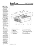
Pass-Through Expansion Kit Installation Instructions First Edition (May 1999) Part Number ER-TL881-EA. A01/138255-001 Compaq Computer Corporation Notice The information in this publication is subject to change without notice. COMPAQ COMPUTER CORPORATION SHALL NOT BE LIABLE FOR TECHNICAL OR EDITORIAL ERRORS OR OMISSIONS CONTAINED HEREIN, NOR FOR INCIDENTAL OR CONSEQUENTIAL DAMAGES RESULTING FROM THE FURNISHING, PERFORMANCE, OR USE OF THIS MATERIAL. THIS INFORMATION IS PROVIDED “AS IS” AND COMPAQ COMPUTER CORPORATION DISCLAIMS ANY WARRANTIES, EXPRESS, IMPLIED OR STATUTORY AND EXPRESSLY DISCLAIMS THE IMPLIED WARRANTIES OF MERCHANTABILITY, FITNESS FOR PARTICULAR PURPOSE, GOOD TITLE AND AGAINST INFRINGEMENT. This publication contains information protected by copyright. No part of this publication may be photocopied or reproduced in any form without prior written consent from Compaq Computer Corporation. © 1999 Compaq Computer Corporation. All rights reserved. Printed in the U.S.A. The software described in this guide is furnished under a license agreement or nondisclosure agreement. The software may be used or copied only in accordance with the terms of the agreement. Compaq, Deskpro, Fastart, Compaq Insight Manager, Systempro, Systempro/LT, ProLiant, ROMPaq, QVision, SmartStart, NetFlex, QuickFind, PaqFax, ProSignia, registered United States Patent and Trademark Office. Neoserver, Netelligent, Systempro/XL, SoftPaq, QuickBlank, QuickLock are trademarks and/or service marks of Compaq Computer Corporation. Microsoft, MS-DOS, Windows, and Windows NT are registered trademarks of Microsoft Corporation. Pentium is a registered trademark and Xeon is a trademark of Intel Corporation. Other product names mentioned herein may be trademarks and/or registered trademarks of their respective companies. Pass-Through Expansion Kit Installation Instructions First Edition (May 1999) Part Number ER-TL881-EA. A01/138255-001 Contents About This Guide Text Conventions ....................................................................................................v Symbols in Text .................................................................................................... vi Symbols on Equipment.......................................................................................... vi Rack Stability....................................................................................................... vii Getting Help ........................................................................................................ vii Compaq Technical Support.......................................................................... viiii Compaq Website .......................................................................................... viii Compaq Authorized Reseller .......................................................................... ix Chapter 1 Overview Mechanism Section Covers ................................................................................. 1-1 Parts and Tools.................................................................................................... 1-2 Chapter 2 Upgrade Procedure Assembly Procedures .......................................................................................... 2-1 Identifying the Parts of the Mechanism ......................................................... 2-1 Orienting the Parts During Assembly............................................................ 2-4 Assembling the Mechanism .......................................................................... 2-5 Installing the Belt ......................................................................................... 2-7 Adding Sections to an Existing Mechanism ....................................................... 2-11 Index iv Pass-Through Expansion Kit Installation Instructions List of Figures Figure 1-1. Cover Assembly Side Plate............................................................... 1-2 Figure 1-2. Mechanism Section Cover ................................................................ 1-2 Figure 2-1. Mechanism External Parts ................................................................. 2-2 Figure 2-2. Mechanism Car ................................................................................ 2-3 Figure 2-3. Car Rear View Showing Belt Block.................................................. 2-3 Figure 2-4. Assembled Mechanism..................................................................... 2-5 Figure 2-5. Tensioner Ramp and Idler Pulley...................................................... 2-7 Figure 2-6. Threading the Belt Around the Motor Drive Pulley ........................... 2-8 Figure 2-7. Belt Ends ......................................................................................... 2-9 Figure 2-8. Belt Block with Belt in Place ...........................................................2-10 Figure 2-9. Aligning the Captive Screws with the Belt Block .............................2-11 List of Tables Table 1-1 Upgrade Kit 120880–B31 Parts............................................................ 1-3 Table 2-1 Required Belt Length........................................................................... 2-8 About This Guide This guide is designed to be used as step-by-step instructions for installation and as a reference for operation, troubleshooting, and future upgrades. Text Conventions This document uses the following conventions to distinguish elements of text: Keys Keys appear in boldface. A plus sign (+) between two keys indicates that they should be pressed simultaneously. USER INPUT User input appears in a different typeface and in uppercase. FILENAMES File names appear in uppercase italics. Menu Options, Command Names, Dialog Box Names These elements appear in initial capital letters. COMMANDS, DIRECTORY NAMES, and DRIVE NAMES These elements appear in uppercase. Type When you are instructed to type information, type the information without pressing the Enter key. Enter When you are instructed to enter information, type the information and then press the Enter key. vi Pass-Through Expansion Kit Installation Instructions Symbols in Text These symbols may be found in the text of this guide. They have the following meanings. WARNING: Text set off in this manner indicates that failure to follow directions in the warning could result in bodily harm or loss of life. CAUTION: Text set off in this manner indicates that failure to follow directions could result in damage to equipment or loss of information. IMPORTANT: Text set off in this manner presents clarifying information or specific instructions. NOTE: Text set off in this manner presents commentary, sidelights, or interesting points of information. Symbols on Equipment These icons may be located on equipment in areas where hazardous conditions may exist. Any surface or area of the equipment marked with these symbols indicates the presence of electrical shock hazards. Enclosed area contains no operator serviceable parts. WARNING: To reduce the risk of injury from electrical shock hazards, do not open this enclosure. Any RJ-45 receptacle marked with these symbols indicates a Network Interface Connection. WARNING: To reduce the risk of electrical shock, fire, or damage to the equipment, do not plug telephone or telecommunications connectors into this receptacle. About This Guide vii Any surface or area of the equipment marked with these symbols indicates the presence of a hot surface or hot component. If this surface is contacted, the potential for injury exists. WARNING: To reduce the risk of injury from a hot component, allow the surface to cool before touching. Power Supplies or Systems marked with these symbols indicate the equipment is supplied by multiple sources of power. WARNING: To reduce the risk of injury from electrical shock, remove all power cords to completely disconnect power from the system. Rack Stability WARNING: To reduce the risk of personal injury or damage to the equipment, be sure that: ■ The leveling jacks are extended to the floor. ■ The full weight of the rack rests on the leveling jacks. ■ The stabilizing feet are attached to the rack if it is a single rack installations. ■ The racks are coupled together in multiple rack installations. ■ A rack may become unstable if more than one component is extended for any reason. Extend only one component at a time. Getting Help If you have a problem and have exhausted the information in this guide, you can get further information and other help in the following locations. viii Pass-Through Expansion Kit Installation Instructions Compaq Technical Support You are entitled to free hardware technical telephone support for your product for as long you own the product. A technical support specialist will help you diagnose the problem or guide you to the next step in the warranty process. In North America, call the Compaq Technical Phone Support Center at 1-800-OK-COMPAQ1. This service is available 24 hours a day, 7 days a week. Outside North America, call the nearest Compaq Technical Support Phone Center. Telephone numbers for world wide Technical Support Centers are listed on the Compaq website. Access the Compaq website by logging on to the Internet at http://www.compaq.com. Be sure to have the following information available before you call Compaq: ■ Technical support registration number (if applicable) ■ Product serial number (s) ■ Product model name(s) and numbers(s) ■ Applicable error messages ■ Add-on boards or hardware ■ Third-party hardware or software ■ Operating system type and revision level ■ Detailed, specific questions Compaq Website The Compaq website has information on this product as well as the latest drivers and Flash ROM images. You can access the Compaq website by logging on to the Internet at http://www.compaq.com. 1 For continuous quality improvement, calls may be recorded or monitored. About This Guide ix Compaq Authorized Reseller For the name of your nearest Compaq Authorized Reseller: ■ In the United States, call 1-800-345-1518. ■ In Canada, call 1-800-263-5868. ■ Elsewhere, see the Compaq website for locations and telephone numbers. blank Chapter 1 Overview This document provides instructions for the addition of sections to the PassThrough mechanism (“the mechanism”) in a TL881 MiniLibrary system. It is intended to be used in conjunction with the Compaq Upgrade Kit, part number 120880–B31 IMPORTANT: These procedures should be performed by a qualified service technician. Mechanism Section Covers The Pass-Through mechanism moves tape cartridges vertically between TL881 MiniLibrary modules. Each module section is covered by an individual sheet-metal enclosure. These covers protect the mechanism during shipping and are an important safety shield during operation. A separate detachable side plate is part of the cover assembly. During installation the side plates should be removed on any mechanism sections located behind a MiniLibrary module; this allows easy access to a cartridge stranded in transit by a commercial power outage. The remaining portion of the cover can be removed also from any section behind a module. IMPORTANT: Both parts of the covers must remain in place over any section of the mechanism that is not behind a MiniLibrary module. Any gaps between modules should remain completely covered. 1-2 Pass-Through Expansion Kit Installation Instructions Figure 1-1 shows the cover assembly side plate (1) and Figure 1-2 shows the mechanism section cover (2). 1 SHR-1224 Figure 1-1. Cover Assembly Side Plate 2 SHR-1225 Figure 1-2. Mechanism Section Cover Overview 1-3 Parts and Tools You need the parts and tools described here. The upgrade kit, part number 120880–B31, contains the parts listed in Table 1-1. Table 1-1 Upgrade Kit 120880–B31 Parts Kit Parts Part Number 1 Instructions (this document) 104159-101 2 Extension Sections 968224-101 2 Safety Covers 968013-101 2 Cover Plates 968026-101 2 Belts 968257-101 1 Support Brace 968216-101 4 Tie Bars 968216-101 8 Button Rivets, Nylon 972502-101 2 M3 x 8 mm sems Phillips pan head screws 970945-308 16 M3 x 20 mm sems Phillips pan head screws 970945-320 1 Kit Contains: Angle brackets; Nut plates; Screws and lock washers for mounting slides; And screws for fastening support braces to slides 606619-002 2 RS-232 Cable Assemblies 968239-004 You need these tools: ■ Flat-head screwdriver ■ No. 1 Phillips screwdriver ■ No. 2 Phillips screwdriver ■ Utility knife ■ 0.050" Allen wrench or paper clip blank Chapter 2 Upgrade Procedure Assembly Procedures Assembly of the Pass-Through mechanism (“the mechanism”) requires experience working with moderately complex mechanisms, and the ability to follow directions carefully. The following sections first provide an overview of the parts and procedures required to assemble and install the mechanism. It will be useful to read these sections through before beginning work. The most common procedure required in the field, adding a section or sections to an existing mechanism, is described in a separate section following the overview. It refers to some of the procedures described in the overview. Identifying the Parts of the Mechanism Locate and identify the mechanism internal and external parts. The mechanism includes the following external parts (Figure 2-1). ■ Motor drive section (1) ■ Extension sections (2) ■ Mechanism base with idler pulley (3) ■ Tie bars (4) ■ Support brace (5) ■ Left and right rack slide extensions (6) Compaq Confidential – Need to Know Required Writer: Don Kaplan Project: Pass-Through Mechanism Expansion Kit Installation Instructions Comments: Part Number: ER-TL881-EA. A01/138255-001 File Name: C-CH2 UP.DOC Last Saved On: 5/13/99 10:01 AM 2-2 Pass-Through Mechanism Expansion Kit Installation Instructions ■ Angle brackets (7) ■ L-shaped nut plates (8). 1 5 2 8 5 7 6 4 6 8 4 8 3 5 6 8 4 SHR-1233 Figure 2-1. Mechanism External Parts NOTE: The slide extensions, (6) in Figure 2-1, are not enclosed with the mechanism parts. They are supplied as part of the installation hardware for the slides that come with each of the modules. The rails for each rack type might be different but the mounting scheme is the same. If you are installing a module, follow the instructions for installing rack slides that appear in both the System User’s Guide and the Service Manual for the TL881 MiniLibrary system. After the rack slides and the slave modules are in place, and after the mechanism is assembled, you will install the mechanism in the rack by attaching the support braces (5) to the slide extensions (6) using the angle brackets (7) and L-shaped nut plates (8). The internal parts you will need to recognize during assembly, the car and the belt block, are shown in Figures 2-2 and 2-3; Figure 2-3 locates the belt block (1) and the captive screws (2). Compaq Confidential – Need to Know Required Writer: Don Kaplan Project: Pass-Through Mechanism Expansion Kit Installation Instructions Comments: Part Number: ER-TL881-EA. A01/138255-001 File Name: C-CH2 UP.DOC Last Saved On: 5/13/99 10:01 AM Upgrade Procedure 2-3 SHR-1234 Figure 2-2. Mechanism Car 1 2 SHR-1235 Figure 2-3. Car Rear View Showing Belt Block Compaq Confidential – Need to Know Required Writer: Don Kaplan Project: Pass-Through Mechanism Expansion Kit Installation Instructions Comments: Part Number: ER-TL881-EA. A01/138255-001 File Name: C-CH2 UP.DOC Last Saved On: 5/13/99 10:01 AM 2-4 Pass-Through Mechanism Expansion Kit Installation Instructions The belt block is fastened to the back of the car with two captive screws (Figure 2-3). Make a careful note of the orientation of the block with respect to the car. Orienting the Parts During Assembly To determine the orientation of an extension section examine the flanges on the edges of the section and note that they are dissimilar. Position the section so that its orientation matches that of the elevator base. Figure 2-4 shows a typical mechanism assembly. The motor drive section always goes on top, and the base section with the idler pulley always goes on the bottom. Extension sections are mounted between the motor drive section and the base section. All sections are joined together with tie bars. For systems up to four sections, two support braces are needed, one attached to the motor drive and one to the base section. For larger systems, a third support brace should be mounted near the center of the mechanism, as shown in Figure 2-4. Compaq Confidential – Need to Know Required Writer: Don Kaplan Project: Pass-Through Mechanism Expansion Kit Installation Instructions Comments: Part Number: ER-TL881-EA. A01/138255-001 File Name: C-CH2 UP.DOC Last Saved On: 5/13/99 10:01 AM Upgrade Procedure 2-5 2 1 1 3 4 5 1 SHR-1236 Support brace; Motor section drive; Extension section; Tie bar; Base section. Figure 2-4. Assembled Mechanism Assembling the Mechanism You need a clean, flat work area such as a table or work bench. The surface should be long enough to support the full height of the mechanism. The height is equal to the height of the stack of modules in your system plus any gaps you intend to include in the stack. Do the following steps to assemble the mechanism. Even though in most cases you are adding to a previously-assembled mechanism, it will help if you take a few minutes to read this section and the next section on installing the belt before you proceed to the section entitled Adding to an Existing Mechanism. Compaq Confidential – Need to Know Required Writer: Don Kaplan Project: Pass-Through Mechanism Expansion Kit Installation Instructions Comments: Part Number: ER-TL881-EA. A01/138255-001 File Name: C-CH2 UP.DOC Last Saved On: 5/13/99 10:01 AM 2-6 Pass-Through Mechanism Expansion Kit Installation Instructions 1. Place the base section (Figures 2-1 and 2-4), with the inside facing down, overhanging the right end of the work area, with the bottom plate of the section toward the right. 2. Place each of the extension sections, with the inside facing down, in a row aligned edge-to-edge beginning with the base section. The bottoms of the sections should be toward the right. Omit the motor drive at this time. 3. Align a support brace over the holes on the rear of the base section (Figure 2-4). 4. Insert two M4 x 20 mm Phillips sems screws through the holes in the support brace into the holes in the base section; tighten the screws. 5. Place pairs of tie bars so that they straddle all of the joints where sections come together. Be sure that the beveled edge is toward the inside corner of the sections. 6. Install two M3 x 20 mm Phillips sems screws through each tie bar into the threaded holes in the flanges of the extension sections; tighten the screws finger tight only. 7. Insert two M3 x 20 mm sems screws through each tie bar into the side of the extension sections; tighten the screws finger-tight only. 8. Press the base section and the first extension section together firmly; then tighten the screws alternately, first the two into the flanges of the base section and the extension section, and then the two into the sides of the base section and the extension section, so that each tie bar is drawn into the inside corner of the sections. IMPORTANT: Be careful not to overtighten these screws. 9. Inspect the joint where the sections come together to ensure that the sections are aligned well. If there is a gap or misalignment, do Step 8 again. 10. Do Steps 8 and 9 for each extension section you add. NOTE: It might be necessary to use suitable blocks to support the row of sections so that neither the motor housing not the bottom flange of the base section touch the work surface while you are connecting the motor drive section. 11. Align a support brace over the holes on the rear of the motor drive section (Figure 2-4). 12. Insert two M4 x 20 mm Phillips sems screws through the support brace into the holes in the motor drive section; tighten the screws. Compaq Confidential – Need to Know Required Writer: Don Kaplan Project: Pass-Through Mechanism Expansion Kit Installation Instructions Comments: Part Number: ER-TL881-EA. A01/138255-001 File Name: C-CH2 UP.DOC Last Saved On: 5/13/99 10:01 AM Upgrade Procedure 2-7 Installing the Belt Do these steps to install the belt. 1. Turn the assembled mechanism over so that the motor points upward. 2. Locate the tensioner ramp in the base section (Figure 2-5). Compress the spring until the hole in the tensioner ramp is aligned with a hole in the base section. Insert an 0.050" Allen wrench or a paper clip through the holes; this sets the idler pulley for zero belt tension. 3. Locate the length of toothed belt that was enclosed with the extension section. Table 2-1 lists the required length of belt for your system. Make sure you have the right length; if you do, cut the belt anywhere between two teeth. 4. With the toothed side of the belt toward you position the right end of the belt about halfway along the elevator. SHR-1238 Figure 2-5. Tensioner Ramp and Idler Pulley 5. Thread the left end of the belt counter-clockwise around the motor drive pulley (Figure 2-6). Compaq Confidential – Need to Know Required Writer: Don Kaplan Project: Pass-Through Mechanism Expansion Kit Installation Instructions Comments: Part Number: ER-TL881-EA. A01/138255-001 File Name: C-CH2 UP.DOC Last Saved On: 5/13/99 10:01 AM 2-8 Pass-Through Mechanism Expansion Kit Installation Instructions 6. Move the left end of the belt to the right and thread it around the idler pulley (Figure 2-5) and back to meet what started out as the right end of the belt. When you hold the two ends of the belt, they should be touching or very slightly overlapping (Figure 2-7). Table 2-1 Required Belt Length Number of Extensions (Base, Motor Drive, Extension) Length of Belt 2 27 inches 3 41 inches 4 55 inches 5 69 inches 6 83 inches SHR-1237 Figure 2-6. Threading the Belt Around the Motor Drive Pulley Compaq Confidential – Need to Know Required Writer: Don Kaplan Project: Pass-Through Mechanism Expansion Kit Installation Instructions Comments: Part Number: ER-TL881-EA. A01/138255-001 File Name: C-CH2 UP.DOC Last Saved On: 5/13/99 10:01 AM Upgrade Procedure 2-9 SHR-1239 Figure 2-7. Belt Ends 7. Locate the belt block and the four screws that hold the belt retaining plates to the block (Figure 2-8). Loosen the four screws and slide the ends of the belt under the plates until they engage the teeth on the block; both ends of the belt should be visible through the gap between the plates. Set the belt so there is only a small space between the ends of the belt (about 1/32"). 8. Tighten the four screws that hold the belt retaining plates. 9. Pull out the Allen wrench or the paper clip from the base section; now the proper tension is applied to the belt. Compaq Confidential – Need to Know Required Writer: Don Kaplan Project: Pass-Through Mechanism Expansion Kit Installation Instructions Comments: Part Number: ER-TL881-EA. A01/138255-001 File Name: C-CH2 UP.DOC Last Saved On: 5/13/99 10:01 AM 2-10 Pass-Through Mechanism Expansion Kit Installation Instructions 2 1 3 SHR-1240 Belt; Visible gap; Block. Figure 2-8. Belt Block with Belt in Place 10. Open the door of the car and locate the two captive screws. Figure 2-9 shows the screws, (2), and also shows the car in the track, although at the time of this step the car has not yet been installed in the track (the figure also shows the car without the door for clarity; don’t remove the door) 11. Turn each screw counter-clockwise until about one thread width is embedded in the car bracket and the screws are held in an upright position. 12. Position the belt block at least six inches from the motor drive pulley. 13. Now you must position the car in the mechanism so it appears as shown in Figure 2-9. Tilt the car so that you can engage the spring-loaded wheels in the track as shown, and position the car so the captive screws are directly over the holes in the belt block. 14. While holding the tilted car in place with one hand, grasp the belt with the other hand several inches from the belt block as shown in Figure 29, and push the belt down (1) until the belt block is pressed against the back of the mechanism. 15. Continue to push the belt down while at the same time compressing the springs and rotating the fixed wheels downward until the fixed wheels are engaged in the other track as shown in the figure, and the captive screws are just protruding into the holes in the belt block; release the car and make sure all the wheels are engaged in the track grooves (continue to press the belt block against the back of the mechanism). Compaq Confidential – Need to Know Required Writer: Don Kaplan Project: Pass-Through Mechanism Expansion Kit Installation Instructions Comments: Part Number: ER-TL881-EA. A01/138255-001 File Name: C-CH2 UP.DOC Last Saved On: 5/13/99 10:01 AM Upgrade Procedure 2-11 2 1 SHR-1198 Figure 2-9. Aligning the Captive Screws with the Belt Block 16. Begin to tighten the captive screws. When both screws are threaded into the belt block partially, release the belt and then continue to tighten the screws until the belt block is seated firmly against the car bracket. Close the car door and secure it. 17. Using nylon button rivets install safety covers over any exposed mechanism sections that will not be covered by modules. 18. If you have not already installed all new modules, go to the section entitled Mounting the Module Rack Slides in the System User’s Guide that was enclosed with the module. NOTE: The 10-32 pan head screws and lock washers required to mount the slides in the rack are included in Kit 606619-001, which is one of the items in this kit. Adding Sections to an Existing Mechanism Before you do this procedure read through the two preceding sections, Assembling the Mechanism and Installing the Belt; it will help you to Compaq Confidential – Need to Know Required Writer: Don Kaplan Project: Pass-Through Mechanism Expansion Kit Installation Instructions Comments: Part Number: ER-TL881-EA. A01/138255-001 File Name: C-CH2 UP.DOC Last Saved On: 5/13/99 10:01 AM 2-12 Pass-Through Mechanism Expansion Kit Installation Instructions understand how to do the steps in this section. To add to an existing mechanism you must first disassemble the mechanism partially, then make the necessary changes using procedures described in the preceding sections. Do the following steps. 1. Locate the support braces on the mechanism (Figures 2-1 and 2-4). To remove the assembly from the rack disconnect the cable that is connected to the motor drive assembly, then remove the two screws that fasten each support brace to angle brackets at the ends. Pull the mechanism straight back until it is clear of the modules. 2. Locate the safety covers over the drive motor section and the base assembly. Note that the covers are held in place by nylon button rivet fasteners. Using a suitable thin-bladed tool, pry up the cover until the fasteners can be removed. Set the covers aside and save the fasteners for later use. 3. Place the mechanism on a suitable work surface with the motor at the left and pointed upward. 4. Open the door of the car to gain access to the captive screws (Figure 2-9), but do not remove the door. Loosen the captive screws until they are disengaged from the belt block. 5. Grasp the far side of the car and pull it toward you to compress the springs until the wheels on the far side are free of the track groove; then rotate the far side of the car up, decompress the springs to free the near-side wheels from their track grooves, and remove the car. 6. Locate the tensioner ramp in the base section (Figure 2-5). Compress the spring until the hole in the tensioner ramp is aligned with a hole in the base section. Insert an 0.050" Allen wrench or a paper clip through the holes. This sets the idler pulley for zero belt tension. 7. Loosen the four screws on the belt block (Figure 2-8) enough so that you can pull the ends of the belt free of the block. 8. Pull the belt free of the motor drive assembly and the base section and set the belt aside. 9. Turn the mechanism over and support it so that neither the motor nor the flange at the bottom of the base assembly is touching the work surface. 10. Remove the eight screws that hold a pair of tie bars in place and separate the mechanism at that joint. 11. You can now add sections as needed and install a new belt, as described in Assembling the Mechanism and Installing the Belt. NOTE: If you are adding a section and do not intend to install a TL881 MiniLibrary module in front of that section, regulatory agency safety regulations required that you install a safety cover over the exposed section. Compaq Confidential – Need to Know Required Writer: Don Kaplan Project: Pass-Through Mechanism Expansion Kit Installation Instructions Comments: Part Number: ER-TL881-EA. A01/138255-001 File Name: C-CH2 UP.DOC Last Saved On: 5/13/99 10:01 AM Index B belt block 2-2 Compq authorized resellers, telephone numbers viii technical support telephone numbers vii http://www.compaq.com viii C captive screws 2-2 car 2-2 Compaq authorized reseller viii compaq upgrade kit part number 1-1 parts 1-1 I icons symbols on equipment vi L length of belt 2-7 E elevator external parts 2-1 internal parts 2-2 existing mechanism 2-13 G M mechanism assembly base section 2-4 extension section 2-4 motor drive section 2-4 support brace 2-4 tie bar 2-4 getting help vii P H parts and tools 1-2 help additional sources vii Compaq website viii 2 Pass-Through Mechanism Expansion Kit Installation Instructions R tools 1-3 RJ-45 receptacle vi U S upgrade kit part number 1-2 section covers 1-1 symbols in text vi symbols on equipment vi W T technical support viii telephone numbers viii tensioner ramp 2-7 text conventions v warnings electrical shock vii rack stability vii work area 2-6 www.compaq.com. viii