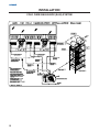
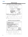
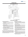
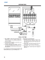
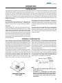
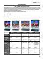
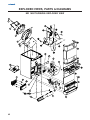
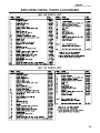
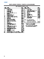
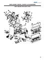
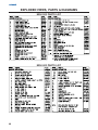
1
MD/MDH SERIES MD 150/175/200/250 & MDH 302/402 Beverage/Ice Dispensers INSTALLATION & SERVICE GUIDE Part Number 5010330 Manitowoc Beverage Equipment 2100 Future Drive Sellersburg, IN 47172-1868 Tel: 812.246.7000, 800.367.4233 Fax: 812.246.9922 www.manitowocbeverage.com In accordance with our policy of continuous product development and improvement, this information is subject to change at any time without notice. December 03, 2007 REV5 FOREWORD Manitowoc Beverage Equipment (MBE) developed this manual as a reference guide for the owner/ operator, service agent, and installer of this equipment. Please read this manual before installation or operation of the machine. A qualified service technician should perform installation and startup of this equipment, consult the Troubleshooting Guide within this manual for service assistance. If you cannot correct the service problem, call your MBE Service Agent or Distributor. Always have your model and serial number available when you call. Your Service Agent ___________________________________________________________________ Service Agent Telephone Number ______________________________________________________ Your Local MBE Distributor ___________________________________________________________ Distributor Telephone Number _________________________________________________________ Model Number ______________________________________________________________________ Serial Number _______________________________________________________________________ Installation Date _____________________________________________________________________ UNPACKING AND INSPECTION Note: The dispenser was thoroughly inspected before leaving the factory. Any damage or irregularities should be noted at the time of delivery. WARRANTY INFORMATION Consult your local MBE Distributor for terms and conditions of your warranty. Your warranty specifically excludes all beverage valve brixing, general adjustments, cleaning, accessories and related servicing. Your warranty card must be returned to Manitowoc Beverage Equipment to activate the warranty on this equipment. If a warranty card is not returned, the warranty period can begin when the equipment leaves the MBE factory. No equipment may be returned to Manitowoc Beverage Equipment without a written Return Materials Authorization (RMA). Equipment returned without an RMA will be refused at MBE’s dock and returned to the sender at the sender’s expense. Please contact your local MBE distributor for return procedures. TABLE OF CONTENTS FOREWORD ........................................................................................................ 2 UNPACKING AND INSPECTION ........................................................................ 2 WARRANTY INFORMATION ............................................................................... 2 SAFETY ............................................................................................................... 6 IMPORTANT SAFETY INSTRUCTIONS ............................................................................. 6 CARBON DIOXIDE WARNING ........................................................................................... 6 QUALIFIED SERVICE PERSONNEL .................................................................................. 6 SHIPPING, STORAGE, AND RELOCATION ....................................................................... 6 ADDITIONAL WARNINGS ................................................................................................. 6 GROUNDING IN STRUCTIONS ......................................................................................... 7 INSTALLATION .................................................................................................... 8 PRE-INSTALLATION CHECK LIST .................................................................................... 8 LEGS ................................................................................................................................ 8 UNIT INSTALLATION ........................................................................................................ 9 DRAINAGE OPTIONS ....................................................................................................... 9 CARB TANK PURGE TUBE ROUTING .............................................................................10 COLD CARB AND AMBIENT SYSTEM PRESSURES ........................................................ 11 AMBIENT BAG-IN-BOX (B-I-B) SYSTEM .......................................................................... 11 COLD CARB BAG-IN-BOX (B-I-B) SYSTEM ...................................................................... 11 TOP MOUNTED ICEMAKER REQUIREMENTS .................................................................13 ICE FLOW RESTRICTOR ................................................................................................. 13 BAFFLE FOR MANITOWOC™ CUBERS ..........................................................................14 BAFFLE FOR "Q" SERIES ICE MACHINES ...................................................................... 14 MANUAL FILL LID FOR DISPENSERS WITH A CUBER ..................................................14 PLUMBING DIAGRAM LOCATION ...................................................................................15 MD-150 6 VALVE PLUMBING DIAGRAM ..........................................................................16 MD-150 6 VALVE FLEX MANIFOLD .................................................................................. 16 MD-175 8 VALVE PLUMBING DIAGRAM ..........................................................................17 MD-175 8 VALVE FLEX MANIFOLD ................................................................................. 17 MD-200/250 8 VALVE PLUMBING DIAGRAM ................................................................... 18 MD-200/250 8 VALVE FLEX MANIFOLD ........................................................................... 18 MD-200/250 10 VALVE PLUMBING DIAGRAM .................................................................19 MD-200/250 10 VALVE FLEX MANIFOLD ......................................................................... 19 MD-302 12 VALVE PLUMBING DIAGRAM ........................................................................ 20 MD-302 12 VALVE FLEX MANIFOLD ............................................................................... 20 MD-402 16 VALVE PLUMBING DIAGRAMS ..................................................................... 21 MD-402 16 VALVE FLEX MANIFOLD ............................................................................... 21 MD-402 20 VALVE PLUMBING DIAGRAMS ..................................................................... 22 MD-402 20 VALVE FLEX MANIFOLD ............................................................................... 22 TABLE OF CONTENTS OPERATION ...................................................................................................... 23 UNIT INSPECTION ........................................................................................................... 23 ICE STORAGE AND DISPENSING ................................................................................... 23 ROCKING CHUTE ICE DISPENSING ................................................................................ 23 COLD PLATE BEVERAGE COOLING ............................................................................... 23 BEVERAGE VALVES ........................................................................................................ 23 AUTO BAG SELECTORS ................................................................................................. 24 B-I-B ................................................................................................................................. 24 PUMPS ............................................................................................................................ 24 RACKING ......................................................................................................................... 24 PRE-MIX & POST-MIX BEVERAGE DISPENSERS .......................................................... 24 BACK ROOM PACKAGE .................................................................................................. 25 BAG-IN-BOX SYSTEM ..................................................................................................... 25 FIGAL SYSTEM ............................................................................................................... 26 CARBONATION ................................................................................................................ 27 INTERNAL CARBONATION .............................................................................................. 27 MD SERIES COUNTERTOP MEASUREMENTS ................................................................ 28 MD SERIES SPECIFICATIONS ........................................................................................ 29 MDH SERIES COUNTERTOP MEASUREMENTS .............................................................. 30 MDH SERIES SPECIFICATIONS ...................................................................................... 31 ROCKING CHUTE ICE DELIVERY SWITCH ADJUSTMENT .............................................. 32 SETTING THE AUTOMATIC AGITATION TIMER ............................................................... 33 115V/220V NON ADJUSTABLE AGITATION TIMER .......................................................... 33 SEQUENCE OF OPERATION ............................................................................................ 34 USER MAINTENANCE ...................................................................................... 35 PREVENTATIVE MAINTENANCE ...................................................................................... 35 HOW TO DISASSEMBLE FOR CLEANING OR MAINTENANCE ....................................... 35 DAILY CLEANING ............................................................................................................. 38 MONTHLY CLEANING ...................................................................................................... 39 BEVERAGE SYSTEM CLEANING ..................................................................................... 40 BAG-IN-BOX SYSTEM ..................................................................................................... 40 FIGAL BEVERAGE SYSTEM ............................................................................................ 41 Installation and Service Manual TABLE OF CONTENTS EXPLODED VIEWS, PARTS & DIAGRAMS ..................................................... 42 MD 150/175/200/250 EXPLODED VIEW ............................................................................ 42 MD 150 PARTS LIST ....................................................................................................... 43 MD 175 PARTS LIST ....................................................................................................... 43 MD 200/250 PARTS LIST ................................................................................................. 44 MDH 302/402 EXPLODED VIEW ....................................................................................... 45 MDH 302 PARTS LIST .....................................................................................................46 MDH 402 PARTS LIST .....................................................................................................46 MD 150 115V PRE-MIX WIRING DIAGRAM ...................................................................... 47 MD 150/175/200 115V WIRING DIAGRAM ........................................................................ 48 MD 150 220V PRE-MIX WIRING DIAGRAM ...................................................................... 49 MD 150/175/200 220V WIRING DIAGRAM ........................................................................ 50 MD 250 115V WIRING DIAGRAM ..................................................................................... 51 MD 250 220V WIRING DIAGRAM ..................................................................................... 52 MDH 302 115V WIRING DIAGRAM ...................................................................................53 MDH 302 220V WIRING HARNESS .................................................................................. 54 MDH 402 115V WIRING DIAGRAM ...................................................................................55 MDH 402 220V WIRING DIAGRAM ...................................................................................56 TROUBLESHOOTING ....................................................................................... 57 PUMP ............................................................................................................................... 57 DRINKS ............................................................................................................................ 58 LIQUID LEVEL CONTROL ................................................................................................ 60 INDEX ................................................................................................................ 63 5 SAFETY IMPORTANT SAFETY INSTRUCTIONS Carefully read all safety messages in this manual. Learn how to operate the MD unit properly. Do not allow anyone to operate the unit without proper training and keep it in proper working condition. Unauthorized modifications to the MD may impair function and/or safety and affect the life of the unit. CARBON DIOXIDE WARNING DANGER: Carbon Dioxide (CO2) displaces oxygen.Exposure to a high concentration of CO2 gas causes tremors, which are followed rapidly by loss of consciousness and suffocation. If a CO2 gas leak is suspected, particularly in a small area, immediately ventilate the area before repairing the leak. CO2 lines and pumps should not be installed in an enclosed space. An enclosed space can be a cooler or small room or closet.This may include convenience stores with glass door self serve coolers.If you suspect CO2 may build up in an area, venting of the B-I-B pumps and / or CO2 monitors should be utilized. QUALIFIED SERVICE PERSONNEL WARNING: Only trained and certified electrical and plumbing technicians should service this unit. All wiring and plumbing must conform to national and local codes. SHIPPING, STORAGE, AND RELOCATION CAUTION: Before shipping, storing, or relocating this unit, syrup systems must be sanitized. After sanitizing, all liquids (sanitizing solution and water) must be purged from the unit. A freezing environment causes residual sanitizing solution or water remaining inside the unit to freeze, resulting in damage to internal components. ADDITIONAL WARNINGS Installation and start-up of this equipment should be done by a qualified service technician. Operation, maintenance, and cleaning information in this manual are provided for the user/operator of the equipment. Save these instructions. Installation and Service Manual SAFETY GROUNDING IN STRUCTIONS WARNING: Risk of electrical shock. Connect to a properly grounded outlet only. This appliance must be grounded. In the event of malfunction or breakdown, grounding provides a path of least resistance for electric current to reduce the risk of electric shock. This appliance is equipped with a cord having an equipment-grounding conductor and a grounding plug. The plug must be plugged into an appropriate outlet that is properly installed and grounded in accordance with all local codes and ordinances. DANGER – Improper connection of the equipment-grounding conductor can result in a risk of electric shock. The conductor with insulation having an outer surface that is green with or without yellow stripes is the equipment grounding conductor. If repair or replacement of the cord or plug is necessary, do not connect the equipment-grounding conductor to a live terminal. Check with a qualified electrician or serviceman if the grounding instructions are not completely understood, or if in doubt as to whether the appliance is properly grounded. Do not modify the plug provided with the appliance – if it will not fit the outlet, have a proper outlet installed by a qualified electrician. WARNING – When using electric appliances, basic precautions should always be followed, including the following: a) Read all the instructions before using the appliance. b) To reduce he risk of injury, close supervision is necessary when an appliance is used near children. c) Do not contact moving parts. d) Only use attachments recommended or sold by the manufacturer. e) Do not use outdoors. f) For a cord-connected appliance, the following shall be included: • Do not unplug by pulling on cord. To unplug, grasp the plug, not the cord. • Unplug from outlet when not in use and before servicing or cleaning. • Do not operate any appliance with a damaged cord or plug, or after the appliance malfunctions or is dropped or damaged in any manner. Return appliance to the nearest authorized service facility for examination, repair, or electrical or mechanical adjustment. g) For a permanently connected appliance – Turn the power switch to the off position when the appliance is not in use and before servicing or cleaning. h) For an appliance with a replaceable lamp – always unplug before replacing the lamp. Replace the bulb with the same type. i) For a grounded appliance – Connect to a properly grounded outlet only. See Grounding Instructions. SAVE THESE INSTRUCTIONS 7 INSTALLATION PRE-INSTALLATION CHECK LIST When installing any system, first make sure the major components are available. Generally the major components necessary for an installation are: Do you have enough space to install the dis Pre-mix system: Is the countertop level? penser or a dispenser and top mounted cuber? Does the top mounted cuber (if utilized) have a minimum of 6 inches (15.3) cm) clearance on all sides? Can the countertop support the weight of the dispenser, or the dispenser/cuber combination plus the weight of the stored ice? Post mix system: CO2 regulator set Product connectors for Figal tank Gas connectors for Figal tank Beverage dispenser Beverage tubing CO2 tank Figal beverage tanks CO2 regulator set Beverage dispenser Beverage tubing CO2 tank Carbonator Stepless (Oetiker) clamps Chain for CO2 tank Stepless (Oetiker) clamps Chain for CO2 tank Figal system also: B-I-B System also: B-I-B connectors Syrup connectors for Figal tank Gas connectors for Figal tank Figal syrup tanks B-I-B regulator set B-I-B rack B-I-B syrup boxes Double Check: Is the countertop level? Do you have enough space to install the dispenser or a dispenser and top mounted cuber? Does the top mounted cuber (if utilized) have a Can the countertop support the weight of the minimum of 6 inches (15.3) cm) clearance on all sides? dispenser, or the dispenser/cuber combination plus the weight of the stored ice? Also consider the location of the following items before installation: Water line Power outlet Drain Heating and air conditioning ducts LEGS CAUTION: It is recommended if an icemaker is installed on top of the dispenser, legs should NOT be installed. Legs are optional equipment with most Servend dispensers. Standard legs are four-inch (10.2 cm) tall painted steel legs. 8 When installing legs on a MD Series dispenser, leg braces should be used. These are metal braces fitting side to side under the dispenser that reinforce the leg attachment area. Installation and Service Manual INSTALLATION UNIT INSTALLATION 1. Place the dispenser in the desired location. tween those pressures proper measures must be taken to regulate them to correct settings. 2. Run the beverage lines and water lines (make sure to install the water connections to the proper inlets. Connection “A” comes from the procon pump and is your carbonated water supply and Connection “B” is your plain water supply. (Refer to plumbing diagrams.) 6. Turn CO2 supply on to the dispenser. Each cold carb pump deck is furnished with a fixed regulator set at 75 psi. Ambient units need to be set between 90 and 100 psi. 3. Install drain plumbing and insulate. 7. Fill bin with ice. (See Drainage Options below) 8. Connect power supply. 4. Set flexible manifold for correct drink settings. 9. Brix beverage valves. 5. Turn water supply on to the dispenser. Water pressure should be between 40 and 55 psi. If not in-be- 10. Meet all code requirements. DRAINAGE OPTIONS The drains for MD Series connects to the drain pan. Option One Option Two Drainage through the bottom of the unit: Drainage through the back of the unit: NOTE: The MDH 302 & 402 will have two drains Radiator clamp 90 elbow fitting Straight fitting Radiator clamp Flexible tubing Radiator clamp Flexible tubing Holes for beverage lines Holes for drain pan drain 9 INSTALLATION CARB TANK PURGE TUBE ROUTING 1. During installation of unit the carbonator tank purge tube (A) must be properly routed to a drain. Once the splash panel has been removed from unit remove twist tie (B) that holds carbonator tank purge tube. A 2. Route carbonator tank purge tube (A) down front of unit and behind drain pan. Be sure not to collapse or kink carbonator tank purge tube during routing from unit to drain. (C) Purge tube is connected to the pressure relief valve on carbonator tank and must be routed to a drain B 3. The carbonator tank purge tube (A) can be routed down through the counter top that unit has been installed on or out the rear of unit. Then install carbonator tank purge tube to a drain. Follow all local and national plumbing codes when routing carbonator tank purge tube to the drain. A C Pressure Relif Valve Drain Pan To Drain 10 A Installation and Service Manual INSTALLATION COLD CARB AND AMBIENT SYSTEM PRESSURES 1. Incoming tap water should be at a minimum pressure of 40 psi and a maximum of 55psi. 2. BIB pressure gauge set for 60 psi. 3. Carbonator Pressure gauge: • Cold Carbonation set for 75 psi. • Ambient systems should be set at 90 psi to 100 psi. NOTE: If incoming water pressure is under 40 psi, a water booster is recommended. If incoming water pressure is over 55 psi, a water regulating valve is required. AMBIENT BAG-IN-BOX (B-I-B) SYSTEM NOTE: Dispenser This is a simplified schematic to show the basic operation of the beverage system. Typical MD Ambient System Overview 5 w/Coldplate Countertop BIB Syrup Pump SYRUP NON-CARBONATED WATER SYRUP CARBONATED WATER 1800 ox n-B p g-I Ba Syru n rto Ca 90100 Tap Water 60 1 CO2 SYRUP CO2 Cylinder CO2 Carbonator Tap Water 3 Tank 4 CO2 SYRUP 2 Drawing #: 5010102-0 COLD CARB BAG-IN-BOX (B-I-B) SYSTEM NOTE: This is a simplified schematic to show the basic operation of the beverage system. MD Series Internal Carbonation Beverage Dispensing System Dispenser Carbonated/Non-carbonated Beverage Manifold Carbonator Tank Countertop SYRUP BIB Syrup Pump Tap Water CO2 1800 60 Tap Water ox n-B g-I p Ba Syru n o rt Ca CO2 3 CO2 Cylinder 1 75 SYRUP 2 4 Dwg#: 5010301-0 11 INSTALLATION COLD CARB BAG-IN-BOX (B-I-B) SYSTEM 12 Installation and Service Manual INSTALLATION TOP MOUNTED ICEMAKER REQUIREMENTS 1 2 3 Location - Avoid placing the dispenser and/or ice machine near heat sources such as radiators, ovens, refrigeration equipment and direct sunlight. Clearances - Six inch (15.2 cm) clearance on all sides of the icemaker is needed. Front of icemaker to be flush with front of dispenser- The front of the icemaker should be flush with the front of the dispenser, as shown in the draw1 2 4 5 ing above. Because the icemaker is flush with the front of the dispenser, some icemakers may overhang at the back of the dispenser. Drains - A separate drain line is required for the ice machine, in addition to a drain line for the ice/beverage dispenser. MD Series dispensers require an adapter kit to install a top-mounted icemaker. Contact your local Servend distributor for the correct adapter kit. 6" (15.2 cm) clearance for cuber 6" (15.2 cm) 6" (15.2 cm) cuber 6" (15.2 cm) 5 6" (15.2 cm) 3 3 4 4 NOTE: For full information about icemaker installation, including plumbing lines connections and electrical requirements, see the icemaker installation manual. ICE FLOW RESTRICTOR For all Servend MD/MDH Series dispensers an ice flow restrictor is available. This ice flow restrictor decreases the amount of ice allowed to enter the ice chute by blocking a small area at the entrance of the dispenser chute. This in turn restricts the flow of ice that is dispensed in to your cup. Ice Flow Restrictor Please refer to the instructions included in kit #5013822 for more information on how to install. 13 INSTALLATION BAFFLE FOR MANITOWOC™ CUBERS When installing a Manitowoc™ “S” series Ice Machine on a Servend MD-series dispenser, a baffle kit is required for proper installation. The baffle kit is designed to prevent ice from lying against the front of the ice machine, and melting down the front of the dispenser. There are two different baffle kits available from Servend. One kit is for the 30" wide “S” series ice machine, and the other kit is for the 22" wide “S” series ice machine. These two Kits are available through your local Manitowoc Distributor. List prices may be subject to change without notification. Please call your local parts distributor for current pricing before ordering. Ice Maker Baffle Installation: 1. Remove both front panels. 2. Examine the ice machine to see if the machine has four screws on the lower front plastic panels. 3. If there are screws, remove them from the countersunk holes on the front surface of the machine, save the screws. 4. Install the deflector, using the four screws removed in step three. 5. Four screws and two backing plates are in the kit. 6. If there are no screws on the ice machine (step 2), pierce the thin plastic countersunk holes, install the backing plates and install the deflector using the screws from the kit. 7. Replace the front panels. Part Number Description 5029518 ........................ Baffle Kit 30” 5029517 ........................ Baffle Kit 22” BAFFLE FOR "Q" SERIES ICE MACHINES 1. Position baffle on top of water well with tab on the front and the other tab inside the water well. 2. Mount the baffle on the left side of the ice maker using the hole and screw provided. MANUAL FILL LID FOR DISPENSERS WITH A CUBER If you are top mounting your MD Series dispenser with a cuber, you will require a lid for the manual fill area at the top, front of the dispenser. 14 If you ordered a Servend dispenser and a cuber at the same time, the manual fill lid was included with the unit. The manual fill lid can be ordered from your local Servend distributor. Installation and Service Manual INSTALLATION PLUMBING DIAGRAM LOCATION The plumbing diagram is printed on a white vinyl label, usually located above the inlet tubes for syrup and later. The plumbing diagram label can be accessed by removing the splash panel of the dispenser. The plumbing diagram label explains which inlet coldplate fittings supply which dispenser valves and water manifolds. On internal carb units the water supply must first be connected to the carbonator pump before plumbing to connection “A” shown on plumbing diagram. The carbonator pump deck must be within six feet of the dispenser for optimum performance. (See BIB installation diagram for system pressure settings). 0 4 SH PU R IC FO E ING PLUMB AM R G DIA Plumbing Diagram 15 INSTALLATION MD-150 6 VALVE PLUMBING DIAGRAM MD-150 6 VALVE FLEX MANIFOLD 16 Installation and Service Manual INSTALLATION MD-175 8 VALVE PLUMBING DIAGRAM MD-175 8 VALVE FLEX MANIFOLD 17 INSTALLATION MD-200/250 8 VALVE PLUMBING DIAGRAM MD-200/250 8 VALVE FLEX MANIFOLD 18 Installation and Service Manual INSTALLATION MD-200/250 10 VALVE PLUMBING DIAGRAM MD-200/250 10 VALVE FLEX MANIFOLD 19 INSTALLATION MD-302 12 VALVE PLUMBING DIAGRAM LEFT RIGHT MD-302 12 VALVE FLEX MANIFOLD (1 PER SIDE) 20 Installation and Service Manual INSTALLATION MD-402 16 VALVE PLUMBING DIAGRAMS LEFT RIGHT MD-402 16 VALVE FLEX MANIFOLD (1 PER SIDE) 21 INSTALLATION MD-402 20 VALVE PLUMBING DIAGRAMS LEFT RIGHT MD-402 20 VALVE FLEX MANIFOLD (1 PER SIDE) 22 Installation and Service Manual OPERATION UNIT INSPECTION Thoroughly inspect the unit upon delivery. Immediately report any damage that occurred during transportation to the delivery carrier. Request a written inspection report from a claims inspector to document any necessary claim. ICE STORAGE AND DISPENSING Servend dispensers are designed to dispense hard, cube ice up to one-inch square. The ice shapes and sizes listed below are recommended for dispensing. Warm “Super Cooled” Ice Before Dispensing “Super Cooled” ice is not recommended for dispensing. “Super cooled” ice is ice that has been stored in freezers below 32oF. Should it be necessary to temporarily use “super cooled” ice, allow the ice to warm at room temperature for 25 to 30 minutes before placing the ice in the dispenser. Dispensing compressed flake “nugget” ice in Servend dispensers takes special handling. Most dispensers require special bin components plus a universal ice management kit. Contact MBE regarding details for your particular installation. ROCKING CHUTE ICE DISPENSING As the customer presses the rocking chute, the arm at the top left rear of the chute pushes upward on the door lock. The door opens until it contacts the stops in the mounting brackets. The plastic arm on the ice chute also activates the lever of the ice dispensing switch. When activated, the micro switch starts the gear motor. The gear motor turns the paddle wheel and agitator arm. The paddle wheel carries ice. Periodic agitation is optional on the MD150 and MD-175 and is standard on the MD-200, MD-250, MD-302 and MD-402. During periodic agitation, the paddle wheel and agitator turn for approximately three seconds every three and one half-hours. The door lock prevents ice from being dispensed during the agitation cycle. (See Also Sequence of Operation) COLD PLATE BEVERAGE COOLING A cold plate is a block of aluminum with serpentine stainless steel tubes molded inside the aluminum block. The cold plate is approximately the same length and width as the bottom of the dispenser bin. Ice sits on top of the cold plate and cools the cold plate. The stainless steel tubes inside the cold plate carry carbonated water (soda water), noncarbonated water (plain water) and syrup to the beverage valves. While flowing through the stainless steel tubes in the cold plate, water and syrup are chilled to serving temperature. BEVERAGE VALVES Post-mix beverage valves are designed to precisely meter the flow of both water and syrup to obtain the proper mixing ratio. The syrup and soda water components of the post-mix beverage are mixed as they leave the beverage valve. 23 OPERATION AUTO BAG SELECTORS These are used on higher volume B-I-B systems where two or more bags of the same product are connected to one pump and one system. An auto bag selector is essentially a valve that automatically changes from one bag (or series of bags) to another bag (or series of bags) of syrup as the bags empty, allowing a constant flow of product. B-I-B The Bag-In-Box system refers to a plastic disposable bag. The B-I-B normally contains 5 gallons of syrup, however some locations offer 2 1/2 or 3 gallon B-I-B units. This plastic bag is then held inside a cardboard or other container. PUMPS The syrup in a B-I-B system is delivered to the beverage system through gas operated pumps. These pumps extract the syrup out of the bags forcing the syrup throughout the system. RACKING Regardless if you are working on pre-mix or post-mix (B-I-B or Figal) system, a place will be designated for placement of the product. A rack (or shelf) system affords systematic placement and complete usage of the beverage paid for. The B-I-B rack allows the boxes to lay properly for syrup dispersal. Please check with your B-I-B syrup supplier. Some boxes must be slightly tilted down, while others may be in virtually any position. The Figal tank rack keeps the newer and full tanks organized at one end of the beverage line with the partial tanks at the other. PRE-MIX & POST-MIX BEVERAGE DISPENSERS Pre-Mix - Only a small number of systems use Pre-Mix, usually for temporary or very low volume dispensing where installation of a carbonator is not warranted. Pre-Mix means that syrup and carbonated water are already mixed at the bottling plant, then chilled at the dispenser location before being served. A memory peg for the meaning of Pre-Mix is that the syrup and carbonated water are mixed together before leaving the beverage valve. Post-Mix - Most beverage systems are Post-Mix. Permanent dispensing locations with a mid to high volume dispensing have Post-Mix systems, such as self-service dispensers in Convenience Stores, Restaurants and Cafeterias. 24 Post-Mix means that syrup and carbonated water (or plain tap water for non-carbonated drinks) are mixed together in the valve nozzle of the dispenser, just before the finished beverage flows into the customer’s cup. A memory peg for the meaning of Post-Mix is that the syrup and water are mixed after leaving the beverage valve. The two common Post-Mix systems are: 1. Bag-in-Box (BIB) - Most often, five gallons of syrup is stored in a plastic bag inside a carton. 2. Figal - Most often, five gallons of syrup is stored in a stainless steel canister. Plumbing Diagram Label The plumbing diagram label explains which inlet cold plate fittings supply which dispenser valves. Installation and Service Manual OPERATION BACK ROOM PACKAGE BAG-IN-BOX SYSTEM Creating Carbonated Water: 1. Incoming tap water - should be at a minimum dynamic pressure of 40 psi and maximum static pressure of 55 psi. 2. Carbonator Water pump motor - Powers the water pump. The water pump motor is part of the carbonator pump deck. 3. Carbonator Water pump - Pumps tap water into the carbonator tank. The water pump is part of the carbonator. The incoming water for the carbonator must be first ran through the pump before connecting to the proper cold plate inlet. 4. Internal/External Carbonator tank - Combines CO2 gas and tap water to form carbonated water. The “carbonator” is the carbonator tank, water pump and water pump motor. On an ambient system, after being carbonated, the carbonated water is fed from the carbonator to the dispenser cold plate for chilling. At the beverage valve, chilled water and chilled syrup are mixed to create the finished beverage. A cold carbonated system pre-chills the water before entering the carbonator tank. Pumping Syrup to the Dispenser: 5. CO2 cylinder - Holds highly pressurized carbon dioxide (CO2). The CO2 cylinder is a steel or aluminum cylinder tank. CO2 gas flows to the primary pressure regulator. 6. Cylinder pressure gauge - Indicates amount of CO2 gas in the cylinder. 7. Primary pressure regulator - Lowers the CO2 gas pressure, to 100 psi, so the CO2 gas will be at the proper pressure to enter the carbonator regulator. 8. Lowered outgoing pressure - Set for 75 psi. Gauge indicated lowered outgoing pressure from the CO2 cylinder after being routed through the primary pressure regulator at 100 psi.. 9. Secondary pressure regulator - Lowers the CO2 gas pressure before the CO2 gas flows to the syrup pump. CO2 pressure, 60 to 75 PSI, activates the syrup pump. 10. Syrup pump - Draws syrup out of the bag-in-box syrup package. Syrup flows through the syrup lines to the dispenser for chilling, then dispensing. There is a syrup pump for each bag-in-box syrup system. 11. Bag-In-Box syrup cartons - Box which contains a plastic bag, filled with syrup. 25 OPERATION FIGAL SYSTEM 1. CO2 cylinder - Holds highly pressurized carbon dioxide (CO2 ). The CO2 cylinder is a steel or aluminum cylinder tank. CO2 gas flows to the primary pressure regulator. 2. Primary pressure regulator - Lowers the CO2 gas pressure, usually to 100 psi. 3. Lowered outgoing pressure gauge - Gauge indicates lowered outgoing pressure from the CO2 cylinder after being routed through the primary pressure regulator. At a T-fitting, this line then forms two branches: One branch feeds CO2 gas to the carbonator tank and the other branch feeds CO2 gas to the Figal tanks. 26 Pumping Syrup to the Dispenser: 4. Secondary pressure regulator - Lowers the CO2 gas pressure, usually at 45-60 psi, before the CO2 gas flows to the Figal syrup tank. Diet syrup is usually 10-15 psi. 5. Syrup pump - Syrup flows through the syrup lines to the dispenser for chilling, then dispensing. 6. Figal tanks - Steel tank which usually holds five gallons of syrup. Several Figal tanks supply the dispenser. Installation and Service Manual OPERATION CARBONATION The purpose of the carbonator is to take water and combine it with CO2 to create carbonated water. Tap water at street water pressure (minimum 40 PSI dynamic or flowing pressure in a 1/2" water line) must be forced into a tank that contains CO2 (usually at 100 PSI) by using a pump to raise the water pressure above the CO2 pressure. CO2 is absorbed into the water as the water passes through the gas. Cooling and agitating the water will allow it to absorb more CO2 gas. Chilling the mixture before dispensing will assist in locking the carbon dioxide into the water. After dispensing, the CO2 may be unlocked from the liquid. The CO2 will gradually leave the liquid due to pressure and temperature changes. Components The agitation of the water & CO2 together in the tank unThe components of the carbonator are: water pump, an der high pressure creates the soda water. The quality of electric motor to operate the pump, carbonator tank carbonation (percent of CO2 mixed in the water) increases as the water temperature decreases and exposure time where the water & CO2 mix, and a water level control. increases. Operation Carbon Dioxide (CO2) leaves the storage tank and ar- The water level in the carbonator tank is controlled by a rives at the carbonator tank through the gas inlet. Water water level control in the tank. This control turns the pump supply enters the carbonator pump inlet at regular street motor off and on to maintain a preset level of liquid in the water line pressure (minimum 40 PSI dynamic or flowing tank. The water level control may be electronic probes or pressure). The water pump increases the pressure of the a mechanical float. water, which allows the water to flow into the carbonator tank. The CO2 and the water mix together in the carbonator to produce the carbonated water that is then sent to the soda dispenser. INTERNAL CARBONATION The carbonator tank has two inlets and one outlet connection, as well as a relief valve and two conductivity probes. The water inlet is a double check valve topped with a 3/8" flared fitting. The carbonator will be pre-plumbed as it leaves the factory. If the carbonator needs to be serviced or if the fittings need to be replaced, make sure a nylon washer is used inside the CO2 inlet fitting to prevent leaks. level control, which is a circuit board mounted inside the electrical box that activates the pump and motor. Removing the cover of the electrical box will grant access to the circuit board. As the control receives a signal from the conductivity probes, it activates the pump motor, which will pump water into the carbonator until the water reaches the high probe. The conductivity probes are used to control the level of water inside the carbonator tank. The red probe, or the “high” probe, is the shorter of the two. When the level of the water reaches the bottom of the red probe, the pump shuts off. When the water level inside the tank goes below the bottom tip of the of the black or low probe. Both probes are wired to the electronic liquid The pump motor and electrical box are mounted together on a single platform. The pump is a standard 125 GPH brass rotary vane pump. The flared fittings accept the same swivel/barb connectors used on the carbonator water connections. Also, water enters the pump from the water source on the side that has the filter. Notes: • Pump Decks for internal carb units must be within 6 feet of unit. • Installation of a carbonator any further away than the recommended distance is at installer/ owner's risk. Known issues can include, but is not limited to poor carbonation and/or erratic carbonation. 27 OPERATION MD SERIES COUNTERTOP MEASUREMENTS Letter Description MD-150 MD-175 MD-200/250 MD-250-36 A Unit Width 22” 24” 30” 36" B Unit Depth 30 1/2" 30 1/2" 30 1/2" 30 1/2" C Outside Ice Bin Depth 22" 22 1/2" 22 1/2" 22 1/2" D Under Unit Width 18" 20" 26" 32" E Under Unit Depth 20 1/2" 20 1/2" 20 1/2" 20 1/2" F Recommended countertop Cut-out* 3"x13" 3"x14" 3"x18" 3"x18" G Maximum Countertop Cut-out* 18"x20 1/2" 20"x20 1/2" 26"x20 1/2" 32"x20 1/2" CAUTION: *Cutting the countertop may decrease its strength. Counter should be braced to support the dispenser countertop weight plus ice storage capacity and weight of icemaker, if applicable. 28 Installation and Service Manual OPERATION MD SERIES SPECIFICATIONS MD Series dispensers have a stainless steel cabinet and lighted merchandiser standard. Beverage valves, coldplate connections, drain connections and electrical components are front serviceable. MD Series dispensers drain through a single 3/4" NPT connection to the drain pan. The standard voltage for MD Series dispensers is 120VAC-60Hz. A power cord is provided with 120VAC-60Hz models only. MD Series dispensers are available in the following optional voltages: • 100VAC-50/60Hz • 220VAC-50Hz • 220VAC-60Hz MD Series dispensers use a 1/7 hp gearmotor. Optimum ambient conditions for MD Series dispensers are between 500F and 950F. MD-150 MD-175 MD-200 MD-250 MD-250-36 Dimensions WxDxH 22" x 30 ½" x 33" 24" x 30 ½" x 34" 30" x 30 ½" x 33" 30" x 30 ½" x 39" 36" x 30 ½" x 39" Ice Storage 150 lbs 175 lbs 200 lbs 250 lbs 250 lbs Beverage Valves 6 8 8 or 10 8 or 10 10 or 12 13 circuit 8 valve: 12 circuit Soft plumbed 3-1-1-3 manifold water circuits, 8 10 valve: 15 circuit hard-plumbed 3-1-2-1-3 manifold syrup circuits Coldplate 9 circuit 3-2-1 manifold 12 circuit 3-1-1-3 manifold 8 valve: 12 circuit 3-1-1-3 manifold 10 valve: 15 Circuit 3-1-2-1-3 manifold Amperage 2.5 FLA 2.8 FLA 2.5 FLA 2.5 FLA 2.5 FLA Agitation Timer Optional Optional Standard Standard Standard Shipping Weight 240 lbs 259 lbs 318 lbs 338 lbs 338 lbs 29 OPERATION MDH SERIES COUNTERTOP MEASUREMENTS Letter Description MDH-302 MDH-402 A Unit Width 42 ¾" 60" B Unit Depth 30 ½ " 30 ½" C Outside Ice Bin Depth 22 ½" 22 ½" D Under Unit Width 38 ¾" 56 ½" E Under Unit Depth 20 ½" 21 ¼" F Recommended Countertop Cut-out* 3" X 32" 3" X 48" G Maximum Countertop Cut-out* 38 ¾" X 20 ½" 56 ½" X 21 ¼" CAUTION: *Cutting the countertop may decrease its strength. Counter should be braced to support the dispenser countertop weight plus ice storage capacity and weight of icemaker, if applicable. 30 Installation and Service Manual OPERATION MDH SERIES SPECIFICATIONS MDH Series dispensers have a stainless steel cabinet and lighted merchandiser standard. Beverage valves, coldplate connections, drain connections and electrical components are front serviceable. MDH Series dispensers drain through a two 3/4" NPT connection to the drain pan. The standard voltage for MDH Series dispensers is 120VAC60Hz. A power cord is provided with 120VAC-60Hz models only. MDH Series dispensers are available in the following optional voltages: • 100VAC-50/60Hz • 220VAC-50Hz • 220VAC-60Hz MDH Series dispensers use two 1/7 hp gearmotor. Optimum ambient conditions for MDH Series dispensers are between 500F and 950F. MDH-302 MDH-302 w/EM MDH-402 MDH-402 w/24" EM MDH-402 w/34" EM DimensionsW xDxH 42 ¾"" x 30 1/2" x 33" 42 ¾" x 30 ½" x 44" 60" x 30 ½" x 32" 60" x 30 ½" x 44" 60" x 30 ½" x 54" Ice Storage 300 lbs 300 lbs 400 lbs 400 lbs 400 lbs Beverage Valves 10 or 12 10 or 12 16 or 20 16 or 20 16 or 20 16 valve: Two (2) 12 circuit 3-1-1-3 manifold 20 valve: Two (2) 15 circuit 3-1-2-1-3 manifold 16 valve: Two (2) 12 circuit 3-1-1-3 manifold 20 valve: Two (2) 15 circuit 3-1-2-1-3 manifold Coldplate Two (2) 9 circuit 3-2-1 manifold Two (2) 9 circuit 3-2-1 manifold 16 valve: Two (2) 12 circuit 3-1-1-3 manifold 20 valve: Two (2) 15 circuit 3-1-2-1-3 manifold Amperage 3.5 FLA 4.0 FLA 4.5 FLA 4.5 FLA 5.0 FLA Agitation Timer Standard Standard Standard Standard Standard Shipping Weight 430 lbs 490 lbs 615 lbs 715 lbs 715 lbs 31 OPERATION ROCKING CHUTE ICE DELIVERY SWITCH ADJUSTMENT 32 1 To properly adjust the switch, first unplug the power cord to the unit then remove the merchandiser. This will give you access to the ice delivery switch located on the left side of the rocking chute. 2 Begin by observing the chute by slowly pushing against the rocking chute. When the ice delivery switch clicks, measure the distance from the door stops on the rocking chute bracket to the door. The distance between the two should be no more than 1/4", but no less than 1/16". 3 The left side of the rocking chute has a tab that pushes up on the ice delivery switch. To adjust it, use needle nose pliers and bend the arm of the switch up or down in order to change the point where the tab makes contact with the switch arm. Installation and Service Manual OPERATION SETTING THE AUTOMATIC AGITATION TIMER Some MD Series ice / beverage dispensers have an optional timer, which agitates ice stored in the dispenser bin. The timer is preset at the factory for three seconds ice agitation every three and one half hours. Beginning July, 1999 this timer is not adjustable. To reset the older style timer, use the following procedure: 1. Place a small screwdriver in the adjustment pot marked “ON” (See illustration at right). 2. Gently turn the adjustment pot counterclockwise until the adjustment pot will no longer turn. One of the cross hairs on the dial will be approximately in the “7 o’clock” position. 3. Turn the adjustment pot clockwise, approximately to the “10 o’clock” position. This is two notches past the zero setting and sets the timer for approximately three seconds of ice agitation. 4. Place a small screwdriver in the adjustment pot marked “OFF” (See illustration at right). 5. Gently turn the adjustment pot counterclockwise until the adjustment pot will no longer turn. One of the cross hairs on the dial will be approximately in the “7 o’clock” position. This sets the adjustment pot at zero hours of timing between agitation periods. 6. Turn the adjustment pot to the right, approximately to the “2 o’clock” position. This is approximately nine notches past the zero setting and sets the timer for agitation approximately every three and one half hours. To test the adjustable timer, turn the “ON” time to the correct three second position. Turn the “OFF” time to the zero “7 o’clock” position. Do not disturb the dispenser for 15 minutes. The timer will operate if good. Dispensers made since July 1999 (99G) have non adjustable timers. To test these timers, unplug the dispenser, wait five seconds, then plug the dispenser in. If the timer is good, it will agitate immediately upon the dispenser being plugged in. 115V/220V NON ADJUSTABLE AGITATION TIMER The agitation timer on this unit is equipped with test pins. This allows you to test the timer by removing the jumper between the two pins. When the jumper is removed the timer will cycle every 55 seconds if it is operating correctly. If the timer is wired correctly and does not cycle approximately every 55 seconds when the jumper is removed, replacement of the timer may be necessary. Make sure to replace the jumper pins when finished. NOTES: This timer is re-settable, timed agitation every 3.5 hours from last dispense on power supply broken. Never operate in normal mode without test pins in place, damage could occur. 33 OPERATION SEQUENCE OF OPERATION Manufactured before early 1994 Manufactured beginning early 1994 Pulley Microswitc Solenoid/Door Mount Door Bumper Plunger Cable Door Solenoid F SH PU IC OR E Customer’s cup presses rocking chute push lever or customer’s hand presses push button. The clear plastic arm at the top and the left rear of the clear plastic chute pushes upward on the door. Customer’s cup presses against the push plate. The push plate raises the microswitch actuator arm located on the right side of the ice dispense chute. The microswitch actuator arm activates the microswitch. The door pivots up from the left and right mounting brackets. The microswitch activates the solenoid, which pulls down the solenoid plunger. The plunger is connected to a cable, which is connected to a pulley, then another cable raises the door of the ice chute. The clear plastic arm at the top and left rear of the ice chute also activates the lever of the micro switch. When activated, the micro switch starts the gear motor. The gear motor turns the paddle wheel and agitator arm. When the paddle wheel turns, ice is carried from the bottom of the bin to the dispense point. Ice falls forward through the open door, into the ice chute and to the customer’s cup. The microswitch also activates the gear motor. The gear motor turns the agitator and paddle wheel, lifting ice from the bottom of the bin to the ice dispense point. Ice falls forward through the open door, through the bin spout, into the ice chute and to the customer’s cup. The door lock keeps the door shut during periodic agitation. Periodic agitation is optional on the MD-150 and MD-175. Periodic agitation is standard on the MD-200, MD-250, MD 250-36, and MDH-302. Push Button Ice Dispensing, Solenoid, Cable Style Door During periodic agitation, the paddle wheel and agitator turn for approximately three seconds every three and one half-hours of non-use. Since ice is brought forward during periodic agitation, ice would fall through the ice dispense door if the door lock was not present. The push button energizes the plunger micro- switch. The microswitch activates the solenoid, which pulls down the solenoid plunger. The plunger is connected to a cable, which is connected to a pulley, then another cable raises the door of the ice chute. Customer’s finger presses the push button, located in the merchandiser frame. The button is labeled, “PUSH FOR ICE”. The microswitch also activates the gear motor. The gear motor turns the agitator and paddle wheel, lifting ice from the bottom of the bin to the ice dispense point. Ice falls forward through the open door, through the bin spout, into the ice chute and to the customer’s cup. 34 Installation and Service Manual USER MAINTENANCE PREVENTATIVE MAINTENANCE Preventative maintenance is a vital part of keeping your Servend dispenser in top condition. Following the guidelines below will assist you in continued trouble free operation of your unit. Contact MBE at 1-800-367-4233 for more information about our ProActive Maintenance Program. 1. Conduct daily maintenance of the machine. Possible excess ice storage reasons: 2. Perform monthly maintenance of the machine. • Storage capacity exceeds daily requirements. 3. Perform periodic maintenance and sanitizing of bev• Low demand during the off season. erage system. • Dispenser oversized with future growth in mind. 4. Do not overfill the dispenser bin with ice. Lower ice storage to meet one day’s needs. If you manu5. Do not allow the dispenser to sit for prolonged perially fill ice, fill only with the appropriate amount of ice. ods of non use with ice in the bin. Fill the dispenser with fresh ice each morning. Do not fill 6. Most ice dispenser service problems are caused the dispenser at night just before shut down. Ice cubes by low usage of the ice dispenser. can freeze together if not dispensed. 7. Do not allow ice to remain in the bin more than a day in order to prevent ice from freezing together and/or stagnant ice. HOW TO DISASSEMBLE FOR CLEANING OR MAINTENANCE NOTE: Sanitize the ice dispenser at Initial Start-UP in addition to monthly sanitizing. You will need screwdriver in order to disassemble. Disassemble parts in the following order: A. B. C. D. C E D G F ER NG DA A B R FO SH PU ICE Merchandiser Ice chute Paddle wheel pin Agitator E. Paddle wheel F. Bin liner G. Paddle wheel Area Accessing a Dispenser Bin Top Mounted with a Manitowoc Cuber: 1. Remove the front panel of the ice machine. 2. Remove the ice deflection baffle. This will give you access to the dispenser bin. Accessing a Dispenser Bin that is Top Mounted with a Manitowoc Cuber and Large Extended Merchandiser in front of the Cuber: 1. Access to the bin is possible through the strip lids on the side of the Dispenser. Disassembling the Dispenser Parts for Bin Cleaning: 1. Remove the front panel of the Manitowoc ice maker. 2. If the Manitowoc ice maker is operating, wait for the sheet of ice to fall into the dispenser bin. When the ice sheet falls into the dispenser bin, immediately place toggle switch of the ice machine to the “OFF” position. If the Manitowoc ice maker is NOT operating, place the toggle switch of the ice machine to the “OFF” position. 3. On MD models without a top mounted cuber, remove the plastic lit from the top of the dispenser. 4. Remove all ice from the dispenser. 5. Disconnect electrical power to the dispenser. 6. On the MD-302 dispenser only, remove the strip lids off the top left and top right of the dispenser bin. 7. For the MD-302 dispenser only, there is a left bin and a right bin. Clean and sanitize one bin, then follow the same procedures on the second bin. 35 USER MAINTENANCE HOW TO DISASSEMBLE FOR CLEANING OR MAINTENANCE 8 10 Agitator arm and paddle wheel pin: 8. Rotate the agitator arm so the paddle wheel pin handle is pointing up, toward the ceiling. For the MD-302 dispenser only, reach inside the bin through the area where the strip lid has been removed. 9. Loosen the hand-removable paddle wheel pin from the agitator by twisting counter clockwise until it snaps from the agitator bar... 10. Then remove the paddle wheel pin from the hole in the agitator. 11. Push the agitator bar toward the back of the unit until the agitator is free of the paddle wheel hub. 12. Move the front of the agitator to one side and slide the agitator forward until the rear of the agitator shaft is clear of the bushing. 13. Remove the agitator from the bin area. 11 9 Paddle wheel, bin liner and paddle wheel area: 14. Slide the paddle wheel from its shaft. 15. Loosen the four knurled fasteners that hold the bin liner in place. 16. Remove the bin liner. 17. Remove the paddle wheel area from the bin. For the MD-302 dispenser only, remove the paddle wheel area to the back of the bin. 14 18. Discard the remaining ice in the bin. 17 15 16 N DA R FO SH PU 36 ICE R GE Installation and Service Manual USER MAINTENANCE HOW TO DISASSEMBLE FOR CLEANING OR MAINTENANCE Disassemble the rocking chute: 1. Loosen the two knurled fasteners that hold the merchandiser in place. 2. Remove the merchandiser. 3. Remove outer bracket. 4. Remove door lock. 5. Remove door. 6. Remove ice chute. 7. Model MD-302 has two rocking chutes. Remove both rocking chutes using the same procedure above. Disassemble the solenoid style chute: 1. Loosen the knurled fastener on both sides of the outer chute and remove chute from the dispenser. 1 4 2 3 SH PU E R IC FO ING PLUMB AM R DIAG 6 I NG PLUMB AM R DIAG 5 SH PU E R IC FO 37 USER MAINTENANCE DAILY CLEANING All cleaning must meet your local health department regulations. The following cleaning instructions are provided as a guide. CAUTION: Use only warm soapy water to clean the exterior of the tower. Do not use solvents or other cleaning agents. Do not pour hot coffee into the drain pan. Pouring hot coffee down the drain pan can eventually crack the drain pan, especially if the drain pan is cold or still contains ice. Clean the exterior and drain pan: 1. Turn off the key switch located on either right or left side of the unit. 2. Lift the grid and remove it from the drain pan. 3. Using mild soap, warm water and a clean cloth, wipe the drain pan and splash panel. Then, rinse with clean, warm water. Allow plenty of warm (not hot) water to run down the drain of the drain pan, to remove syrup residue that can clog the drain opening. 4. Wash the grid, then rinse with clean water. Place the grid back in the drain pan. 5. Wash all exterior surfaces of the unit with warm water and a clean cloth. Wipe again with a clean, dry cloth. Clean the dispensing valves: 6. Remove nozzles and diffusers from beverage valves. 7. Rinse nozzle and diffuser with warm, clean water. 8. Clean nozzles and diffusers with soapy water and a soft bristle brush. 9. Clean the underside of the beverage valves with warm, soapy water. Rinse with clean damp towel. 10. Replace nozzles and diffusers on valves. 11. Turn on the key switch. 38 Installation and Service Manual USER MAINTENANCE MONTHLY CLEANING Clean and sanitize the ice bin and cold plate: 1. Unplug unit and remove all ice from the ice bin. 2. Mix a solution of mild detergent to clean the dispenser bin and components. 3. Wash the ice bin using a sponge and the mild detergent solution. 4. Using the mild detergent solution and a soft bristle brush or clean cloth, clean the following dispenser parts: • Cold plate • Entire bin • Paddle wheel • Paddle wheel area • Agitator • Paddle wheel pin • Ice Chute • Rear bushing • Motor shaft • Strip lids (where applicable) Removable front merchandiser Agitator Ice bin Beverage valve Stainless steel bin liner Cold plate Ice Water Paddle wheel Syrup Cold plate Gear motor Drain pan Rocking chute ice dispense chute 5. Rinse all the parts in clean, running water. 6. Prepare 2 gallons of sanitizing solution by mixing a 1/2 ounce of household bleach (that contains 5.25% sodium hypochlorite) with 2 gallons of 120°F water. The mixture should not exceed 100 PPM of chlorine. Or mix a solution of any approved sanitizer, following the directions for mixing and applying the sanitizer.. 7. Sanitize the ice bin and cold plate with the sanitizing solution for at least 10 seconds. 8. Allow to air dry. Do not rinse. Reassembling the dispenser parts: 9. Reassemble parts in the following order: • Bin liner • Paddle wheel • Agitator • Paddle wheel pin • Ice chute • Merchandiser 10. Hand tighten all knurled fasteners. 11. Pour in fresh, sanitary ice and replace the plastic lid on the top of the dispenser. 12. Plug in the unit’s electrical cord. 13. Check for proper ice dispensing. S PU OR HF ICE I NG PLUMB AM R DIAG 39 USER MAINTENANCE BEVERAGE SYSTEM CLEANING Sanitize the beverage system at initial start-up as well as regularly scheduled cleaning. The drain pan must be in place under soda valves, to carry away detergent and sanitizing agents that will be flushed through valves. BAG-IN-BOX SYSTEM The procedure below is for the sanitation of one syrup circuit at a time. Repeat to sanitize additional circuits. You will need the following items to clean and sanitize the Bag-in-Box (BIB) beverage system: • • • • Three (3) clean buckets Plastic brush or soft cloth Mild detergent Unscented bleach (5% Na CL O) or Commercial sanitizer • Bag-In-Box bag connector 1. Prepare the following in the buckets: • Bucket 1 - warm to hot tap water for rinsing. • Bucket 2 - mild detergent and warm to hot water. • Bucket 3 - mix a solution of unscented bleach (5% Na CL O) or commercial sanitizer and warm to hot water. Mixture should supply 100 PPM available chlorine (1/4 oz. bleach to 1 gallon water). 2. Disconnect the “syrup-line side” of the bag-in-box connector. 3. Rinse connector with warm tap water. 4. Connect syrup connector to BIB connector and immerse both into Bucket 1. A “bag-side” connector can be created by cutting the connector from an empty disposable syrup bag. 5. Draw rinse water through system until clean water is dispensed. Most beverage valves allow the syrup side to be manually activated by depressing the syrup pallet. 6. Connect Bucket 2 to system. 7. Draw detergent solution through system until solution is dispensed. 8. Repeat steps 2-7 until all syrup circuits contain detergent solution. 9. Allow detergent solution to remain in the system for 5 minutes. 40 Installation and Service Manual USER MAINTENANCE BAG-IN-BOX SYSTEM 10. Connect Bucket 3 to system. 11. Draw sanitizing solution through system until solution is dispensed. 12. Repeat step 11 until all syrup circuits contain sanitizer solution. 13. Allow sanitizer solution to remain in system for 15 minutes. 14. Remove nozzles and diffusers from beverage valves. 15. Scrub nozzles, diffusers and all removable valve parts (except electrical parts) with a plastic brush or a soft cloth and the detergent solution. 16. Soak nozzles, diffusers and removable valve parts (except electrical parts) in sanitizer for 15 minutes. 17. Replace nozzles, diffusers and valve parts. 18. Connect Bucket 1 to system. 19. Draw rinse water through system until no presence of sanitizer is detected. 20. Attach syrup connectors to BIB’s. 21. Draw syrup through system until only syrup is dispensed. 22. Discard first 2 drinks. FIGAL BEVERAGE SYSTEM 1. Prepare the following in three clean Figal tanks: • Rinse tank - fill with room temperature tap water. • Detergent tank - mix approved beverage system cleaner with warm water as directed. • Sanitizing tank - mix a solution of unscented bleach (5% Na CL O) or commercial sanitizer and warm to hot water. Mixture should supply 100 PPM available chlorine (1/4 oz. bleach to 1 gallon water). 2. Disconnect all product and water lines from product tanks and remove carbonator. 3. Locate the Figal syrup tank for the circuit to be sanitized. Remove both quick disconnects from the Figal syrup tank. Rinse quick disconnects in tap water. 4. Connect rinse tank to the syrup line. Draw clean rinse water through the valve until syrup is flushed from the system. 5. Connect detergent tank to the syrup line and draw detergent through the valve for two minutes. Then, allow remaining detergent to stay in the system for five minutes. 6. Connect rinse tank to the syrup line. Draw clean rinse water through the valve until detergent is flushed from the system. 7. Remove valve nozzle and diffuser as shown in Daily Cleaning instructions on Pages 25 and 26. Using a plastic brush or a soft cloth and warm water, scrub the nozzle, diffuser, bottom of the dispensing valve and cup lever, if applicable. 8. Place removable valve parts (EXCEPT solenoids) in sanitizing solution for 15 minutes. 9. Replace valve diffuser and nozzle on the beverage valve. 10. Connect sanitizer tank to the syrup line and draw sanitizer through the valve for two minutes. Allow sanitizer to remain in the system for a minimum of 15 minutes. 11. Reconnect syrup and carbonated water lines. 12. Draw syrup through the lines to rinse the system. Discard drinks until at least two cups of satisfactory tasting beverage are dispensed through the valve. 41 EXPLODED VIEWS, PARTS & DIAGRAMS MD 150/175/200/250 EXPLODED VIEW 42 Installation and Service Manual EXPLODED VIEWS, PARTS & DIAGRAMS MD 150 PARTS LIST MD 175 PARTS LIST 43 EXPLODED VIEWS, PARTS & DIAGRAMS MD 200/250 PARTS LIST 44 Installation and Service Manual EXPLODED VIEWS, PARTS & DIAGRAMS MDH 302/402 EXPLODED VIEW 45 EXPLODED VIEWS, PARTS & DIAGRAMS MDH 302 PARTS LIST MDH 402 PARTS LIST 46 Installation and Service Manual EXPLODED VIEWS, PARTS & DIAGRAMS MD 150 115V PRE-MIX WIRING DIAGRAM CAUTION ELECTRICAL SHOCK HAZARD DISCONNECT POWER BEFORE SERVICING MERCHANDISING LAMP (250) BLACK OPTIONAL THERMOSTAT MERCHANDISING LAMP IN BLACK PURPLE ORANGE OUT WHITE LIGHT STARTER BALLAST BLACK BLACK BALLAST 5 1 OPTIONAL AUDIBLE ALARM BLUE 3 BLUE WHITE GRAY 4 2 RED YELLOW OPTIONAL AGITATION TIMER BUZZER 3 2 1 WHITE TIMER PURPLE BLACK BLACK ORANGE WHITE WHITE LIGHT STARTER G OPTIONAL EMPTY LIGHT ICE DISPENSE SWITCH BLUE YELLOW BLUE NO COMMON NC BLACK MOTOR POWER CORD PREMIX 115 VOLT 5029411-0 47 EXPLODED VIEWS, PARTS & DIAGRAMS MD 150/175/200 115V WIRING DIAGRAM TO RESET TRANSFORMER: CAUTION (115 VOLT UNITS ONLY) 1. DISCONNECT POWER SUPPLY. 2. PRESS RESET BREAKER SWITCH ON TRANSFORMER. 3. REPLACE MERCHANDISER (FRONT ENCLOSURE). 4. RECONNECT POWER SUPPLY. ELECTRICAL SHOCK HAZARD DISCONNECT POWER BEFORE SERVICING 115 VOLT MERCHANDISING LAMP BLACK PURPLE WHITE OPTIONAL THERMOSTAT IN OPTIONAL AGITATION TIMER BALLAST BLACK OUT 4 2 BLACK LOAD BLUE WHITE BLACK LOAD LINE OPTIONAL AUDIBLE ALARM BLUE WHITE BLACK PURPLE BLACK GRAY WHITE BLUE LINE 1 BLUE WHITE 5 TRANSFORMER 3 RED YELLOW ORANGE BLACK LIGHT STARTER BLACK G BUZZER 3 W 2 1 TIMER BLUE WHITE ORANGE WHITE BLUE NO VALVE KEYSWITCH YELLOW BLUE OPTIONAL POWER CORD COMMON NC ICE DISPENSE SWITCH BLACK OPTIONAL EMPTY LIGHT BLACK MOTOR BLACK PUSH PUSH BLACK BLACK WHITE WHITE BEVERAGE VALVE 48 ALL REMAINING VALVES ARE WIRED IN PARALLEL BEVERAGE VALVE PN#: 5029413 REV#: 0 Installation and Service Manual EXPLODED VIEWS, PARTS & DIAGRAMS MD 150 220V PRE-MIX WIRING DIAGRAM CAUTION ELECTRICAL SHOCK HAZARD DISCONNECT POWER BEFORE SERVICING MERCHANDISING LAMP (250) BLACK OPTIONAL THERMOSTAT MERCHANDISING LAMP IN BLACK PURPLE ORANGE OUT WHITE OPTIONAL AGITATION TIMER LIGHT STARTER BALLAST BLACK BLACK 5 1 WHITE OPTIONAL AUDIBLE ALARM BLUE 3 BLUE GRAY 4 2 BALLAST RED GREEN YELLOW G BUZZER 3 2 1 BLACK BLACK BROWN ORANGE PURPLE WHITE WHITE LIGHT STARTER N L1 TIMER WHITE BLUE OPTIONAL EMPTY LIGHT ICE DISPENSE SWITCH BLUE YELLOW BLUE NO COMMON NC BLACK MOTOR 220/240 VOLT 5029427-0 49 EXPLODED VIEWS, PARTS & DIAGRAMS MD 150/175/200 220V WIRING DIAGRAM CAUTION 220/240 VOLT ELECTRICAL SHOCK HAZARD DISCONNECT POWER BEFORE SERVICING WHITE RED MERCHANDISING LAMP PURPLE BLACK OPTIONAL THERMOSTAT BALLAST BLACK OUT WHITE BLACK BLACK LINE LOAD LOAD N L1 LINE OPTIONAL AUDIBLE ALARM BLUE 2 1 TIMER WHITE WHITE BLUE NO YELLOW NC WHITE BLUE ICE DISPENSE SWITCH OPTIONAL BLACK ORANG COMMON E OPTIONAL EMPTY LIGHT BLACK VALVE KEYSWITCH BUZZER 3 BLACK BLUE RED BLUE PURPLE WHITE BROWN GRAY 1 ORANGE WHITE 5 BLUE 3 BLUE BLUE BLACK TRANSFORMER YELLOW GREEN BLACK 4 2 YELLOW OPTIONAL AGITATION TIMER G IN BLUE MOTOR BLACK PUSH BEVERAGE VALVE 50 PUSH BLACK BLACK WHITE WHITE ALL REMAINING VALVES WIRED IN PARALLEL BEVERAGE VALVE PN#: 5029429 REV. 0 Installation and Service Manual EXPLODED VIEWS, PARTS & DIAGRAMS MD 250 115V WIRING DIAGRAM TO RESET TRANSFORMER: CAUTION (115 VOLT UNITS ONLY) 1. DISCONNECT POWER SUPPLY. 2. PRESS RESET BREAKER SWITCH ON TRANSFORMER. 3. REPLACE MERCHANDISER (FRONT ENCLOSURE). 4. RECONNECT POWER SUPPLY. ELECTRICAL SHOCK HAZARD DISCONNECT POWER BEFORE SERVICING 115 VOLT WHITE RED OPTIONAL MERCHANDISING LAMP BLACK PURPLE OPTIONAL MERCHANDISING LAMP PURPLE BLACK OPTIONAL AGITATION TIMER 2 WHITE OPTIONAL THERMOSTAT IN BLACK YELLOW RED 4 BLACK BALLAST BALLAST BLUE BLACK ORANGE BLACK OUT WHITE BLUE WHITE B BLACK WHITE BLACK LINE LOAD LOAD LINE OPTIONAL AUDIBLE ALARM BLUE BLACK LIGHT STARTER LIGHT RED STARTER WHITE BLACK GRAY PURPLE 1 BLUE WHITE 5 TRANSFORMER 3 BLACK 3 W G BUZZER 2 1 TIMER BLUE ORANG E WHITE BLUE BLACK NO WHITE YELLOW NC ICE DISPENSE SWITCH BLACK BLUE VALVE KEYSWITCH OPTIONAL EMPTY LIGHT COMMON OPTIONAL POWER CORD MOTOR BLACK PUSH BEVERAGE VALVES PUSH BLACK BLACK WHITE WHITE BEVERAGE VALVES PN#:5029414 REV. 0 51 EXPLODED VIEWS, PARTS & DIAGRAMS MD 250 220V WIRING DIAGRAM CAUTION 220/240 VOLT ELECTRICAL SHOCK HAZARD DISCONNECT POWER BEFORE SERVICING WHITE RED OPTIONAL MERCHANDISING LAMP BLACK PURPLE OPTIONAL MERCHANDISING LAMP PURPLE BLACK OPTIONAL AGITATION TIMER G 4 2 WHITE OPTIONAL THERMOSTAT IN BLACK YELLOW RED BLACK BALLAST BLUE BALLAST BLACK ORANGE BLACK OUT PURPLE LINE 1 WHITE WHITE LOAD BLUE BLACK WHITE LOAD BLACK LINE BLUE WHITE 5 OPTIONAL AUDIBLE ALARM BLUE BLACK PURPLE GRAY BROWN BLUE N L1 TRANSFORMER GREEN 3 BUZZER 3 BLACK 2 WHITE LIGHT STARTER LIGHT STARTER 1 RED TIMER BLUE WHITE ORANG E WHITE BLUE BLACK NO WHITE YELLOW NC ICE DISPENSE SWITCH BLACK BLUE VALVE KEYSWITCH OPTIONAL EMPTY LIGHT COMMON OPTIONAL MOTOR BLACK PUSH BEVERAGE VALVES 52 PUSH BLACK BLACK WHITE WHITE ALL REMAINING VALVES WIRED IN PARALLEL BEVERAGE VALVES PN#:5029430 REV. 0 Installation and Service Manual EXPLODED VIEWS, PARTS & DIAGRAMS MDH 302 115V WIRING DIAGRAM TO RESET TRANSFORMER: CAUTION (115 VOLT UNITS ONLY) 1. DISCONNECT POWER SUPPLY. 2. PRESS RESET BREAKER SWITCH ON TRANSFORMER. 3. REPLACE MERCHANDISER (FRONT ENCLOSURE). 4. RECONNECT POWER SUPPLY. ELECTRICAL SHOCK HAZARD DISCONNECT POWER BEFORE SERVICING OPTIONAL MERCHANDISING LAMP BLACK OPTIONAL MERCHANDISING LAMP BALLAST BALLAST ICE DISPENSE SWITCH BLUE BLUE LINE LOAD LOAD WHITE WHITE LINE RED WHITE LINE OPTIONAL AUDIBLE ALARM BLUE BLACK 1 BLACK BLACK GRAY LOAD OUT ORANGE 4 3 5 COMMON PURPLE PURPLE YELLOW 2 LINE LOAD NO NC YELLOW OPTIONAL AGITATION TIMER BLACK ICE DISPENSE SWITCH IN BLUE BLACK BLUE BLUE NO NC TRANSFORMER BUZZER 3 RED 2 1 LIGHT BLACK STARTER LIGHT WHITE STARTER TIMER G WHITE BLUE VALVE KEYSWITCH WHITE OPTIONAL OPTIONAL EMPTY LIGHT POWER CORD BLUE BLUE WHITE COMMON BLACK TRANSFORMER BLACK OPTIONAL THERMOSTAT PUSH WHITE BLUE BEVERAGE VALVES ALL REMAINING VALVES ARE WIRED IN PARALLEL LEFT MOTOR PUSH BLACK RIGHT MOTOR BEVERAGE VALVES ALL REMAINING VALVES ARE WIRED IN PARALLEL 5029415 REV. 0 53 EXPLODED VIEWS, PARTS & DIAGRAMS MDH 302 220V WIRING HARNESS CAUTION 220/240 VOLT ELECTRICAL SHOCK HAZARD DISCONNECT POWER BEFORE SERVICING OPTIONAL MERCHANDISING LAMP BLUE BLUE BALLAST ICE DISPENSE SWITCH BLACK BLACK BLACK 5 LOAD 1 LOAD LOAD WHITE WHITE WHITE LINE WHITE BLACK BROWN LINE OPTIONAL AUDIBLE ALARM BLUE LOAD LINE BLACK TRANSFORMER 3 GRAY 4 LINE BLUE BLUE WHITE YELLOW 2 OUT YELLOW OPTIONAL AGITATION TIMER BLACK ICE DISPENSE SWITCH NO NC IN BLUE ORANGE NO NC BLUE BLACK BLUE OPTIONAL THERMOSTAT COMMON WHITE BALLAST RED RED BLUE TRANSFORMER BLUE RED RED BLUE BLUE COMMON BLUE BLUE OPTIONAL MERCHANDISING LAMP BUZZER 3 2 1 TIMER BLUE WHITE BLACK WHITE OPTIONAL L1 N WHITE BLUE VALVE KEYSWITCH BLUE BROWN OPTIONAL EMPTY LIGHT G BLUE WHITE BLUE PUSH WHITE BLUE BEVERAGE VALVES ALL REMAINING VALVES ARE WIRED IN PARALLEL 54 LEFT MOTOR PUSH BLACK RIGHT MOTOR BEVERAGE VALVES ALL REMAINING VALVES ARE WIRED IN PARALLEL 5029431 REV. 0 Installation and Service Manual EXPLODED VIEWS, PARTS & DIAGRAMS MDH 402 115V WIRING DIAGRAM 55 EXPLODED VIEWS, PARTS & DIAGRAMS MDH 402 220V WIRING DIAGRAM TO RESET TRANSFORMER: CAUTION (115 VOLT UNITS ONLY) MDH-402 1. DISCONNECT POWER SUPPLY. 2. PRESS RESET BREAKER SWITCH ON TRANSFORMER. 3. REPLACE MERCHANDISER (FRONT ENCLOSURE). 4. RECONNECT POWER SUPPLY. ELECTRICAL SHOCK HAZARD DISCONNECT POWER BEFORE SERVICING DWG#: 5029432 REV. 0 220/240 VOLT RED WHITE RED WHITE OPTIONAL MERCHANDISING LAMP OPTIONAL MERCHANDISING LAMP BLACK BLACK PURPLE PURPLE PURPLE PURPLE BALLAST BALLAST BLACK LIGHT STARTER LIGHT STARTER BLACK RED WHITE RED WHITE MERCHANDISING LAMP MERCHANDISING LAMP BLACK BLACK PURPLE PURPLE WHITE BALLAST WHITE BALLAST BLACK BLACK BLACK LOAD BLUE BLACK LOAD LINE WHITE BLACK BLACK WHITE 5 WHITE BLACK LOAD BLACK LINE BLACK BLACK BLACK G LIGHT STARTER BLUE WHITE BLUE YELLOW BLUE NO COMMON NC ICE DISPENSE SWITCH BLACK BROWN LIGHT STARTER WHITE OPTIONAL BLACK MOTOR PUSH PUSH PUSH BLACK BLACK WHITE ALL ADDITIONAL VALVES ARE WIRED IN PARALLEL ICE DISPENSE SWITCH BLACK BLACK WHITE WHITE BEVERAGE VALVE BEVERAGE VALVE COMMON NC BLACK PUSH WHITE YELLOW BLUE L1 N OPTIONAL MOTOR BLACK BLUE NO VALVE KEYSWITCH BLACK 56 LOAD BLUE WHITE VALVE KEYSWITCH BEVERAGE VALVE LINE 1 WHITE PURPLE BLACK 4 2 3 WHITE WHITE WHITE RED LINE TRANSFORMER WHITE 1 WHITE BLACK TRANSFORMER YELLOW 4 2 3 5 PURPLE OPTIONAL AGITATION TIMER WHITE BLACK RED YELLOW OPTIONAL AGITATION TIMER ALL ADDITIONAL VALVES ARE WIRED IN PARALLEL BEVERAGE VALVE BLACK Installation and Service Manual TROUBLESHOOTING PUMP PROBLEM POSSIBLE CAUSE CORRECTIVE ACTION Black and/or red probe shorted Remove probes and bend straight or replace with new probe(s) Problem with motor or motor wiring Check line voltage first. Check AC voltage across load terminals on Liquid Level Control. If voltage is 120 plus or minus 10%, replace motor or motor wiring. Problem with Liquid Level Control Board. Check line voltage first. If AC voltage across load terminals is not 120 plus or minus 10%, replace the Liquid Level Control Board. Water pressure from water source is not high enough. Verify water pressure leading into pump inlet is 40 psi minimum with pump running. Pump will not run but tank appears to be always full. Common Lead (Green) shorted out to Red wire (High Probe) Verify Green and Red wires are not touching. Pump will not run but tank level appears to be below start level. Common Lead (Green) shorted out to Black wire (Low Probe) Verify Green and Black wires are not touching. Pump motor does not shut off. Problem with Liquid Level Control Board Short the "H & L" terminals on the Liquid Level Control Board. If motor does not shut off, replace Liquid Level Control Board. Probe Harness Connection may be open. Verify connections are good or replace the wiring harness. Water may not be reaching top probe in carb tank. Verify tank is not filled with CO2 or air by pulling relief valve up and letting air escape until water begins coming out. High Lead (Red) open or not connected. Verify Red lead wire is connected from tank to unit. Common lead (Green) open or not connected. Verify Green lead wire is connected from tank to unit. Problem with probe or probe harness. Check motor and motor wires by removing red and black wires from the Liquid Level Control Board. If okay, short "H & L" terminal on Liquid Level Control Board. If motor stays off, verify probes and bend straight or replace. Verify with meter. Problem with motor or motor wiring. Measure AC voltage across load terminals on Liquid Level Control Board. If line voltage is 120 plus or minus 10% replace motor or motor wiring. Pump motor does not pump. Pump motor intermittent 57 TROUBLESHOOTING PUMP PROBLEM POSSIBLE CAUSE CORRECTIVE ACTION Pump motor intermittent Problem with Liquid Level Control Board. Check line voltage first. If AC voltage across load terminals on Liquid Level Control Board is not 120 plus or minus 10%, replace the Liquid Level Contorl board. Pump motor starts and stops, short cycles, as soon as water level drops below Red (High) probe. Black (Low) Lead wire is open or disconnected. Verify connections and continuity of black wire from Liquid Level Control Board to Probes on Carb Tank. Pump motor starts and stops, short cycles, as soon as water level drops below Black (Low) probe. Red and Black Leads are switched with each other. Verify Red Lead is going to Red probe and Black Lead is going to Black probe. Pump short cycles from below high probe to just above high probe - Low probe has no effect. Red and Green Leads are switched with each other. Verify Red Lead is going to Red Probe and Green Lead is going to Ground Screw on tank Black and Green Leads are switched with each other. Verify Black Lead is going to Black Probe and Green Lead is going to Ground Screw on tank. DRINKS CONDITION Warm drinks INVESTIGATION Is the compressor running? No CHECK CORRECTION Power switch off or Compressor switch off Move switch to "on" position Ice bank control Check / replace control box Compressor overload Check / replace overload Start relay Check / replace relay Compressor Check / replace compressor Note A: It is important to remember that anytime the refrigeration system is opened the refrigerant should be recovered, a new drier installed and the proper charge of refrigerant weighed into the refrigeration system. No water, syrup or gas Is there power to the dispensing unit? 58 No power Plug in unit or reset breaker Power to control box Replace fuse or control box Is power coming throught the key switch? Key switch "off" Turn switch "on" Key switch defective Replace key switch Is there power to the key switch? No power through the transformer Reset/replace transformer Installation and Service Manual TROUBLESHOOTING DRINKS CONDITION Water only dispensing Syrup and CO2 only dispensing INVESTIGATION No pressure Carbonator CHECK CORRECTION Regulator(s) out of adjustment Check/adjust regulator(s) Out of CO2 Install fresh tank Defective regulator(s) Check/repair/replace regulator(s) CO2 line pinched, kinked or obstructed Check/repair/replace CO2 line No power Check power supply. Plug in carbonator or reset breaker. Water supply Make sure water is turned "on" Replace water filter Check/clean/replace pump strainer Check/clean/repair water check valve Check for frozen water line. Internal Carbonator unit only. Syrup and plain water only dispensing One valve will not dispense anything Beverage dispensed is too sweet No pressure Is there power to the valve? Is the ratio (brix) of the drink correct? Defective carbonator Check/repair/replace carbonator pump, motor, electrode or liquid level control. Out of CO2 Install fresh tank HP regulator out of adjustment Adjust HP regulator to the proper setting Defective HP regulator Check/repair/replace HP regulator CO2 line pinched, kinked or obstructed Check/repair/replaceCO2 line Broken wire or loose connection Replace/repair wire or connector Bad microswitch Replace microswitch Flow control out of adjustment Adjust the flow control Insufficient soda flow due to Adjust CO2 pressure or change the low carbonator pressure tank Beverage is not sweet enough Drinks are foaming Is the ratio (brix) of the drink correct? Are system pressures correct? Low CO2 pressure due to leaks Repair CO2 leaks Obstruction in the water or soda line Clean out the lines Flow control out of adjustment Adjust the flow control Soda flow too high Reset CO2 pressure or replace regulator if necessary Obstruction in syrup line Clean out the syrup line Over carbonation Check CO2 supply. Reset pressure or replace regulator if necessary Dirty lines/valves Clean/sanitize entire system 59 Installation and Service Manual TROUBLESHOOTING LIQUID LEVEL CONTROL START Does Pump motor come on? Yes No Remove red and black wires from LLC. Yes Is pump motor operation intermittent ? No Black and/or red probe shorted. Remove probes, straighten or replace if necessary. Yes Does pump motor come on? Short H and C terminals on LLC. No Measure AC voltage across load terminals on LLC. Does the pump motor shut off? No Check pump motor and wiring. Yes Is line voltage (– 10%) present ? No Replace LLC END Yes Check probe harness, harness connections and water supply. Installation and Service Manual INDEX B F O T Back Room Package ............... 25 brixing ....................................... 2 FOREWORD .............................. 2 Operation .................................. 6 TROUBLESHOOTING 57, 58, 59, 60 H P health department ................... 38 Power outlet ............................. 8 I Q C Carbon Dioxide ......................... 6 CAUTION .............. 9, 28, 31, 39 claims ...................................... 23 Cleaning .................................... 2 CO2 ........................................... 7 CO2 monitors ............................ 7 D U INSPECTION .............................. 2 Qualified Service Personnel ..... 6 INSTALLATION 8, 9, 10, 11, 12, 13, 14, 15, 16, 17, 18, 19, 20, 21, 22 R Installation Date ........................ 2 Instructions ............................. 38 regulations .............................. 38 irregularities .............................. 2 Relocation ................................. 6 return procedures .................... 2 damage .............................. 2, 23 delivery .............................. 2, 23 L Diagrams 42, 43, 44, 45, 46, 47, 48, 49, 50, 51, 52, 53, 54, 55, 56 location ..................................... 8 dispensing valves .................. 38 distributor .................................. 2 M Drain .......................................... 8 MBE ........................................... 2 ducts ......................................... 8 Model Number ........................... 2 modifications ............................. 6 E Monthly Cleaning .................... 39 exterior ................................... 38 S SAFETY ............................... 6, 7 sanitizing ................................... 7 Serial Number ........................... 2 service assistance ................... 2 Service Personnel .................... 6 Shipping .................................... 6 Shipping, Storage, Relocation .. 6 soapy water ........................... 39 solvents .................................. 39 start-up ..................................... 6 Storage ..................................... 6 Unit Inspection ........................ 23 UNPACKING .............................. 2 W Warning .................................... 6 WARRANTY INFORMATION ..... 2 Water line .................................. 8 water-to-syrup ratio. See brixing Wiring Diagrams 48, 49, 50, 52, 53, 55, 56 Manitowoc Beverage Equipment 2100 Future Drive Sellersburg, IN 47172-1868 Tel: 812.246.7000, 800.367.4233 Fax: 812.246.9922 www.manitowocbeverage.com In accordance with our policy of continuous product development and improvement, this information is subject to change at any time without notice. 5009448 December 03, 2007 REV5