1
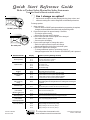
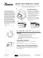
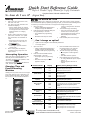
Training Manual
50 Hz
DECS11MA ................. (P1330217M)
DES11EA .................... (P1330218M)
DFS11EA..................... (P1330220M)
RCS511A..................... (P1330214M)
RS511MB .................... (P1330211M)
RS511P ....................... (P1330212M)
RFS511SW2A ............. (P1330223M)
UCS11MA.................... (P1330228M)
UFS11EA..................... (P1330230M)
URCS511A .................. (P1330226M)
URS511MB.................. (P1330224M)
URS511P ..................... (P1330225M)
US11EA....................... (P1330229M)
1100 Watt 50 Hz − 1
March 2005
MENUMASTER
COMMERCIAL MICROWAVE OVEN
R
www.amanacommercial.com
International Commercial Microwave-Technical Information
230/240 V, 50 Hz Models
DECS11MA
DFS11EA
RS511MB
RFS511SW2A
UFS11EA
URS511MB
US11EA
P1330217M
P1330220M
P1330211M
P1330223M
P1330230M
P1330224M
P1330229M
DES11EA
RCS511A
RS511P
UCS11MA
URCS511A
URS511P
P1330218M
P1330214M
P1330212M
P1330228M
P1330226M
P1330225M
• Due to possibility of personal injury or property damage, always contact an authorized technician for servicing or
repair of this unit.
• Refer to Service Manual 16025963 for installation, operating, testing, troubleshooting, and disassembly
instruction.
!
CAUTION
All safety information must be followed as provided in Service Manual 16025963.
!
WARNING
To avoid the risk of electrical shock, personal injury or death, disconnect power to oven and discharge capacitor
before servicing, unless testing requires it.
Models
Power Source
Voltage AC
Amperage (Single Unit)
Frequency
Single Phase, 3 wire grounded
Plug
Power Output
Nominal microwave energy (IEC705)
Minimum temperature rise (∆T)
Operating Frequency
Power Consumption
Cook Condition Microwave
Dimensions
Cabinet
Width
Height
Depth
Oven Interior
Width
Height
Depth
Weight
Crated
Uncrated
DECS11MA, DES11EA,
DFS11EA, RCS511A,
RS511MB, RS511P,
RFS511SW2A
UCS11MA, UFS11EA,
URCS511A, URS511MB,
URS511P, US11EA
230 VAC
16 A
50 Hz
X
CEE 7/7 Schuko; 16A
240 VAC
13 A
50 Hz
X
BS 1363A; 13A
1100 Watts
11ºF / 5.5ºC
2450 MHz
1100 Watts
11ºF / 5.5ºC
2450 MHz
1900 Watts / 8.3 Amps
1900 Watts / 8.3 Amps
21 3/4"
14 1/4"
20 1/4"
55 cm
36.2 cm
51.4 cm
21 3/4"
14 1/4"
20 1/4"
55 cm
36.2 cm
51.4 cm
14 1/4"
9"
16 3/8"
36.2 cm
22.6 cm
41.6 cm
14 1/4"
9"
16 3/8"
36.2 cm
22.6 cm
41.6 cm
56 lbs.
50 lbs.
25 kg
23 kg
56 lbs.
50 lbs.
25 kg
23 kg
Quick Start Reference Guide
Refer to Product Safety Manual for Safety Statements
CLEAN FILTER
This oven displays CLEAN FILTER at user
defined intervals. When the message
displays Amana recommends cleaning
the air filter thoroughly. Cleaning the air
filter will not shut off the message.
The message will stop displaying
automatically after 24 hours. Depending
on microwave use and environmental
conditions, the filter may need to be
cleaned more frequently. Once the
frequency is determined, set the option
for the appropriate time frame.
7
Preprogrammed
Pads
To cook food using preprogrammed
cooking sequences:
1. Open oven door and place food
in oven. Close door.
2. Press desired pad.
3. Oven begins to cook.
4. At end of cooking cycle oven
beeps and shuts off.
QTY QTY 2X
2X Programming
(some models)
To change the cooking factor:
1. Open oven door.
2. Press and hold pad 1 for
approximately 5 seconds.
3. Press pad to be reprogrammed.
4. Press the QTY 2X pad.
5. Press a numbered pad to
change the cooking factor.
• Cooking factor can be set
from 10% to 100%.
• Default is 80%.
• Pad 5 would change the
cooking factor to 50%.
6. Press START pad to save
changes.
Complete Owner’s Manual available online
Oven Wall Clearances
A
B
C
A—For North American (UL/CSA) models, allow at least
2” (5.1 cm) of clearance around top of oven. For
International (50 Hz) models, allow at least 12” (30
cm) of clearance around top of oven. Proper air
flow around oven cools electrical components. With
restricted air flow, oven may not operate properly
and life of electrical parts is reduced.
B—Allow at least 2” (5.1 cm) between air discharge on
back of oven and back wall.
C—Allow at least 2” (5.1 cm) of clearance around sides
of oven.
So...how do I use it?
(Electronic Control)
Manual Operation
To cook food using a specific entered time and power level:
1. Open oven door and place food in oven. Close door.
2. Press TIME ENTRY pad and enter cooking time.
3. Press a power level pad to change power level if desired (some models).
• COOK LEVEL displays with the power setting.
4. If stage cooking is desired, press TIME ENTRY pad and repeat steps
2 through 4, (some models).
5. Press START pad.
6. At end of cooking cycle oven beeps and shuts off.
Programming Items
1.
2.
3.
4.
5.
6.
Open oven door.
Press and hold pad 1 for approximately 5 seconds.
Press pad to be reprogrammed.
Enter cooking time by using the number pads.
Press a power level pad to change power level if desired.
If stage cooking is desired, press TIME ENTRY pad.
• Display briefly shows the stage number.
• Display changes to cook time and power level for the next stage.
7. Enter cook time and power level as in steps 4 and 5 (some models).
• To enter another cooking stage for that pad, press TIME ENTRY pad
again.
• Up to four different stages can be programmed (some models).
8. Press START pad to set new programming changes to the pad.
NOTE: To discard changes, press STOP/RESET pad or close oven door.
QTY 2X Pad
1.
2.
3.
4.
(some models)
Open oven door and place food in oven. Close door.
Press QTY 2X pad.
Press desired preprogrammed pad or pad sequence.
Oven begins cooking. Displayed cooking time is the total of original
cooking time and added 2X time.
The switching operation of this microwave oven can cause voltage fluctuations on the supply line. The operation of this oven under
unfavorable voltage supply conditions can have adverse effects. This device is intended for the connection to a power supply
system with a maximum permissible system impedance Zmax of 0.2 Ohms at the interface point of the user’s supply. The user
has to ensure that this device is connected only to a power supply system which fulfills the requirement above. If necessary, the
user can ask the public power supply company for the system impedance at the interface point.
Quick Start Reference Guide
Refer to Product Safety Manual for Safety Statements
Complete Owner’s Manual available online
?
Can I change an option?
Options such as single or double pad programming, beep volume, and
maximum cooking time can be changed to suit individual preferences.
To change options:
DO NOT power spray
No metal pans
1. Open oven door.
• If door is closed or RESET pad is pressed before programming is complete,
changes are discarded and microwave exits programming mode.
2. Press and hold pad 2 for approximately 5 seconds.
• This begins options mode.
• Microwave will beep and 0P: displays.
3. Press number pad that controls option to be changed.
• See table below for options.
• Current option will display.
4. Press number pad again to change the option.
• Each time pad is pressed, option will change.
• Match code displayed with code for desired option.
5. Press START pad to save changes.
• To change additional options, repeat steps 3 and 4.
• Changes appear after door is closed or STOP/RESET pad is pressed.
Numbered Pads
Display
1
OP:10
Options (Factory Settings in Bold)
3 second beep.
End of Cycle Beep
OP:11
Continuous beep until door is opened.
OP:12
5 beep bursts until door is opened.
2
OP:20
Eliminates beep.
Speaker Volume
OP:21
Sets volume to low.
OP:22
Sets volume to medium.
OP:23
Sets volume to high.
3
OP:30
Prevents beep when pad is pressed.
Key Beep
OP:31
Allows beep when pad is pressed.
4
OP:40
15 seconds after oven door is opened, keyboard disabled.
Keyboard Enable
Window
OP:41
30 seconds after oven door is opened, keyboard disabled.
OP:42
1 minute after oven door is opened, keyboard disabled.
OP:43
2 minutes after oven door is opened, keyboard disabled.
5
OP:50
Prevents adding heating time while oven is heating.
Add Time During
Heating
OP:51
Allows heating time to be changed while oven is heating when a memory pad
is pressed.
6
OP:60
Allows oven to resume heating time countdown after door is opened during
cycle.
Reset Door Open
OP:61
Cancels heating time count down after door is opened during cycle.
7
OP:70
Allows 60 minutes of heating time (some models).
(some models)
OP:71
Allows 10 minutes of heating time.
Maximum Heating Time
8
OP:80
Allows use of preprogrammed pads only.
Manual Operation
OP:81
Allows use of manual time entry and preprogrammed pads.
9
OP:90
Allows 10 (0-9) preprogrammed pads.
(some models)
OP:91
Allows 100 (00-99) preprogrammed pads.
0
OP:00
Do not display message.
Clean Filter Message
OP:01
Display message for 24 hours every 7 days.
OP:02
Display message for 24 hours every 30 days.
OP:03
Display message for 24 hours every 90 days.
Double Digit Operation
Part No.12804405
Revised 10/04
For full product documentation visit:
™
www.amanacommercial.com/wavelink
© 2004 Amana Appliances
Amana, Iowa 52204
Quick Start Reference Guide
Refer to Product Safety Manual for Safety Statements
Complete Owner’s Manual available online
Oven Wall Clearances
The switching operation of this
microwave oven can cause voltage
fluctuations on the supply line. The
operation of this oven under unfavorable
voltage supply conditions can have
adverse effects. This device is intended
for the connection to a power supply
system with a maximum permissible
system impedance Zmax of 0.2 Ohms
at the interface point of the user’s
supply. The user has to ensure that
this device is connected only to a
power supply system which fulfills the
requirement above. If necessary, the
user can ask the public power supply
company for the system impedance at
the interface point.
A
B
C
A—For North American (UL/CSA) models,
allow at least 2” (5.1 cm) of clearance
around top of oven. For International (50 Hz)
models, allow at least 12” (30 cm) of
clearance around top of oven. Proper air
flow around oven cools electrical
components. With restricted air flow, oven
may not operate properly and life of
electrical parts is reduced.
B—Allow at least 2” (5.1 cm) between air
discharge on back of oven and back wall.
C—Allow at least 2” (5.1 cm) of clearance
around sides of oven.
DO NOT power spray
No metal pans
So...how do I use it?
(Mechanical Dial)
Heating
1. Open oven door, place food in oven, and close oven door.
2. Turn time entry knob clockwise to desired time.
• Cooking time can be set up to 6 minutes.
• Oven begins operation and time counts down.
3. When cooking time has elapsed, microwave energy stops and oven
signal sounds.
Interrupting Operation
Open oven door to interrupt operation or turn time entry knob
counterclockwise to “0”.
To resume microwave oven operation, close door and turn knob.
Changing Time and Canceling Mistakes
Heating time can be changed at any time while the oven is operating. Turn
knob to desired new setting. To set cooking time to zero, turn knob
counterclockwise to “0”.
Part No.12804404
Revised 10/04
For full product documentation visit:
™
www.amanacommercial.com/wavelink
© 2004 Amana Appliances
Amana, Iowa 52204
Quick Start Reference Guide
Refer to Product Safety Manual for Safety Statements
Complete Owner’s Manual available online
So...how do I use it?
(Digital Dial)
Heating
1.
2.
3.
4.
5.
:30 QUICK SET Pad
Open oven door, place food in oven,
and close oven door.
Turn time entry knob clockwise until
desired time displays.
• Factory default setting for cooking
time is 10 minutes. Cooking time can
be changed and set to 60 minutes.
(Refer to section on changing
options)
Press a power level pad to change
power level, if desired. If no power
level is selected, unit will default to
100%.
• Power level can be set from full
power (100%), to 70%, 50% or
DEFROST (20%).
AR
T button.
Press ST
STAR
ART
• Oven begins operation and time
counts down.
When cooking time has elapsed,
microwave energy stops and oven
signal sounds.
Interrupting Operation
Open oven door to interrupt operation or turn
time entry knob counterclockwise to “0”.
To resume microwave oven operation, close
AR
T .
door and press ST
STAR
ART
If time was changed to “0”, time will need to be
AR
T.
reset, and then press ST
STAR
ART
Changing Time and
Power/Canceling
Mistakes
Allows you to reheat for 30 seconds at 100% (full) power by simply pressing
the :30 QUICK SET pad. By repeatedly pressing this pad, you can extend the reheating time to
5 minutes by 30 second increments. To change the time assigned to this pad:
1.
2.
Open oven door.
• If door is closed before programming is
complete, changes are discarded.
Press and hold the :30 QUICK SET pad
for approximately 5 seconds.
• This activates the programming
mode.
• Microwave will beep and either
3.
4.
?
1.
2.
current or assigned time will show
in display.
Turn Dial to change time setting.
• Time can be set from zero (0:00)
seconds to five minutes (5:00).
• If the assigned time is 0:00, the :30
QUICK SET pad is effectively
disabled.
Press START pad to save changes.
Can I change an option?
Options can be changed to suit individual preferences.
To change options:
Open oven door.
• If door is closed before programming is
complete, changes are discarded and
microwave exits options programming
mode.
Press and hold the Hidden Pad for
approximately 5 seconds.
• This begins options programming
mode.
• Microwave will beep and 0P:-appears in display.
3.
4.
5.
Press the Hidden Pad to advance to
the desired option to be changed.
• See table below for options.
Turn Dial to change option setting.
• 0P: and option number appear in
display.
• See table below for options.
Press START pad to save changes.
• To change additional options, repeat
steps 2 - 5.
• Changes appear after door is
closed.
Numbered Pads
Display
1
OP:10
3 second continuous beep.
End of Cycle Beep
OP:11
Continuous beep until door is opened.
OP:12
5 beep bursts until door is opened.
2
OP:20
Eliminates beep.
Speaker Volume
OP:21
Sets volume to low.
OP:22
Sets volume to medium.
OP:23
Sets volume to high.
3
OP:30
Prevents beep when pad is pressed.
Key Beep
OP:31
Allows beep when pad is pressed.
4
OP:40
15 seconds after oven door is opened, keyboard disabled.
Keyboard Enable
Window
OP:41
30 seconds after oven door is opened, keyboard disabled.
OP:42
1 minute after oven door is opened, keyboard
disabled.
Heating time and power level can be changed
at any time while the oven is operating. Turn
knob to desired new setting. To set cooking
time to zero, turn knob counterclockwise to
“0”.
Options (Factory Settings in Bold)
OP:43
2 minutes after oven door is opened, keyboard disabled.
5
OP:50
Prevents adding heating time while oven is heating.
Add Time During
Heating
OP:51
Allows heating time to be changed while oven is
heating when a memory pad is pressed.
6
OP:60
Allows oven to resume heating time countdown after door
is opened during cycle.
OP:61
Cancels heating time count down after door is opened
during cycle.
Reset Door Open
OP:70
Allows 60 minutes of heating time.
OP:71
Allows 10 minutes of heating time.
0
OP:00
Do not display message.
Clean Filter Message
OP:01
Display message for 24 hours every 7 days.
OP:02
Display message for 24 hours every 30 days.
OP:03
Display message for 24 hours every 90 days.
7
(some models)
Hidden
Pad
Maximum Heating Time
Part No.12804404
Revised 10/04
For full product documentation visit:
™
www.amanacommercial.com/wavelink
© 2004 Amana Appliances
Amana, Iowa 52204
Disassembly Procedures
To avoid the risk of electrical shock, personal injury, or death, disconnect power to oven and discharge the
capacitors before following any disassembly procedures.
Cavity
TCO Magnetron
TCO
Stirrer Motor
H.V.
Capacitor
Circuit
Protector
Diode
Line Filter
Top
Antenna
Magnetron
Transformer
Oven Door
Blower Motor
Interlock Switch
Control Panel
Splatter Shield
Oven Tray
Disassembly Procedures
To avoid the risk of electrical shock, personal injury, or death, disconnect power to oven and discharge the
capacitors before following any disassembly procedures.
Door Removal
1. Disconnect power to oven.
2. Open oven door, remove top hinge cap, and slowly lift door to disengage the hinge pins at top and bottom.
Top hinge cap
Top
hinge
cap
3. To reinstall door, place top pin into slot first, then align bottom pin.
4. Reinstall top hinge cap.
Choke
cover
Outer
Door
panel
Latch
assembly
Door
Handle
Spring
Door frame/
choke assembly
* Tighten side screw first and apply Loctite
Disassembly Procedures
To avoid the risk of electrical shock, personal injury, or death, disconnect power to oven and discharge the
capacitors before following any disassembly procedures.
Control Panel Removal
1.
2.
3.
4.
Disconnect power to oven and remove outer case.
Disconnect and label wires from controller/timer.
Open oven door.
Remove screw securing top of control panel to cavity. Lift control panel up and out to release tabs.
Disconnecting Wire Terminals
All wire terminals are locking-type terminals.
Proceed as follows to disconnect wire terminals:
Insulated terminals:
Grasp insulator pod and pull back. DO NOT PULL ON WIRE.
1 Grasp
Insulator
Pod
Wire
2 Pull
Non-insulated terminals:
Use a small blade screwdriver to depress locking-tab and pull on terminal. DO NOT PULL ON WIRE.
1 Release
locking-tab
2 Pull
Wire
Disassembly Procedures
To avoid the risk of electrical shock, personal injury, or death, disconnect power to oven and discharge the
capacitors before following any disassembly procedures.
Interlock Switch
Tab
Monitor
Switch
NC
COM
NO
Primary
Switch
COM
Secondary
Switch
NO
COM
Tab
NOTE: After repairing the door or the interlock system, it is necessary to check the switch continuity before
operating the oven.
Adjusting Interlocks
The interlock monitor, primary, and secondary switches act as a final safety switch, protecting the operator from
microwave energy. After adjusting the interlock switch assembly, verify wires are correctly connected.
For door fit and switch operation, switch bracket is adjustable.
1.
2.
3.
4.
5.
Disconnect power to oven and remove outer case, (see "Outer Case" procedure).
Loosen switch bracket mounting screws.
Close oven door, move switch bracket toward rear of oven until door gap is less than 1/64–inch (0.5 mm).
Hold switch bracket securely for proper switch operation and door fit, retighten screws.
Open oven door slowly, watching the switches. Verify switches release in the following order.
• Primary interlock switch
• Secondary interlock switch
• Interlock monitor switch
NOTE: Adjust the switch bracket until all switches operate in proper sequence.
6. Close the oven door slowly, watching the switches. Verify switches activate in the following order.
• Interlock monitor switch
• Secondary interlock switch
• Primary interlock switch
7. When proper switch sequence has been achieved, tighten the switch bracket securely.
A microwave leakage test must be performed anytime a door assembly is removed, replaced, disassembled,
or adjustment of switch bracket is performed.
Component Testing Procedures
To avoid the risk of electrical shock, personal injury, or death, disconnect power to oven and discharge the
capacitors before servicing, unless testing requires power.
Illustration
Component
Thermal cutout
Testing
Disconnect all wires from TCO.
Measure resistance across terminals.
Cavity TCO ............................................
Magnetron TCO .....................................
Diode
Discharge Capacitor
Remove diode lead from capacitor and
connect ohmmeter.
Circuit Protector
Reverse leads for second test.
Discharge Capacitor
Remove circuit protector leads from
capacitor and connect ohmmeter.
Capacitor
Reverse leads for second test.
Discharge Capacitor
Remove wires from capacitor terminals
and connect ohmmeter, set on highest
resistance scale to terminals.
Magnetron
Also check between each terminal and
capacitor case.
Discharge Capacitor
Remove wires from magnetron and
connect ohmmeter to terminals. Also
check between each terminal and
ground.
Blower motor
Transformer
NOTE: Ohmmeter must contain a
battery of 6 volts minimum.
Infinite resistance should be
measured in one direction and 50KΩ
or more in the opposite direction.
NOTE: Ohmmeter must contain a
battery of 6 volts minimum.
Between Terminals: Meter should
momentarily deflect towards zero
then return to over 5 MΩ. If no
deflection occurs, or if continuous
deflection occurs, replace capacitor.
Terminal to Case: Infinite resistance
Between Terminals: Less than 1 Ω
Each terminal to ground measures
Infinite resistance.
Note: This test is not conclusive. If
oven does not heat and all other
components test good replace the
magnetron and retest.
Approximately 72 – 82 Ω
Remove all wires from motor.
Measure resistance across terminals.....
Secondary
Closed at 32°F (0°C) and
Opens at 230°F (110°C)
Closed at 140°F (60°C) and
Opens at 320°F (160°C)
Infinite resistance should be
measured in one direction and 50KΩ
or more in the opposite direction.
Remove all wires from motor.
Measure resistance across coil ..............
Stirrer motor
Results
Approximately 12.8 – 13.5 KΩ
Discharge Capacitor
Remove all wires from terminals.
Filament
Primary
Noise filter board
Measure resistance from:
Primary.................................................
Filament ...............................................
Secondary to Ground screw on
transformer stack..................................
Power In terminals .................................
Power Out terminals ..............................
Less than <3 Ω
Less than <1 Ω
Approximately 110 – 125 Ω
230 / 240 VAC
230 / 240 VAC
If no power in, check power outlet.
If no power out, check fuses.
Component Testing Procedures
To avoid the risk of electrical shock, personal injury, or death, disconnect power to oven and discharge the
capacitors before servicing, unless testing requires power.
Illustration
Component
Interlock switch assembly
3
Monitor
4
1
2
5
Primary
6
Secondary
Testing
Disconnect wires to switch.
With door open measure resistance from:
Monitor - Terminal 3 - 4..........................
Primary - Terminal 1 - 2 .........................
Secondary - Terminal 5 - 6.....................
Indicates continuity
Infinite Ω
Infinite Ω
With door closed measure resistance from:
Monitor - Terminal 3 - 4..........................
Primary - Terminal 1 - 2 .........................
Secondary - Terminal 5 - 6.....................
Infinite Ω
Indicates continuity
Indicates continuity
After verifying or replacing the
module, reconnect wires to switch
and check operation of monitor circuit
before operating the oven.
Lamp receptacle
Test continuity of receptacle terminals.
Wire Harness
Test continuity of wires
Service Test Mode:
Electronic Control Panel
Open door, Press and Hold pad 3 for 5
seconds to enter service test mode.
Press Pad 1 ................................................
Press Pad 2 ................................................
Press Pad 3 ................................................
Press Pad 4 ................................................
Error codes:
Hidden
Pad 2
Hidden
Pad 1
70%
50%
DEFROST
Service Test Mode:
Results
Press Pad 5 ................................................
Press Pad 6 ................................................
Press Pad 7 ................................................
Press Pad 8 ................................................
Press Pad 9 ................................................
Press Pad 0 ................................................
Stop/Reset Pad ...........................................
E-08 ............................................................
E-09 ............................................................
E-10 ............................................................
Electronic Dial Control Panel
Open door, Press and Hold Hidden Pad
2 for 5 seconds to enter service test
mode.
Press Hidden Pad 2 ....................................
Press Hidden Pad 2 again .........................
START
Press Hidden Pad 2 again .........................
Press Hidden Pad 2 again .........................
Press Hidden Pad 2 again .........................
Press Hidden Pad 2 again .........................
Indicates continuity with bulb
installed.
Indicates continuity
SERVICE appears in the display
Indicates number of hours
magnetron has been turned on
Indicates number of times
magnetron tube has cycled
Indicates number of door cycles
CLEAR (Press START pad to
reset service data.)
Indicates amperage
N/A
N/A
N/A
N/A
N/A
Exit Service Test Mode
Replace Control Board
Replace Control Board
Shorted or Open Keypad – Test
and replace if necessary
Enters into Service Test Mode
Indicates number of magnetron
hours
Indicates magnetron tube cycles
Indicates number of door cycles
Indicates amperage
Turn dial to Clear Info – When
dial is rotated display indicates
CLEARED INFO
Component Testing Procedures
To avoid the risk of electrical shock, personal injury, or death, disconnect power to oven and discharge the
capacitors before servicing, unless testing requires power.
Illustration
Electronic Control
RS511P
URS511P
Electronic Control
DFS11EA
RCS511A
UFS11EA
URCS511A
Electronic Control
DES11EA
US11EA
Dial Control
DECS11MA
RCS511MB
UCS11MA
URS511MB
Component
Keyboard assembly
Testing
Continuity is indicated as
100 Ω and below.
1
2
3
4
5
6
7
8
9
10
11
Keyboard assembly
Continuity is indicated as
100 Ω and below.
1
2
3
4
5
6
7
8
9
10
11
Keyboard assembly
Continuity is indicated as
100 Ω and below.
1
2
3
4
5
6
7
8
9
10
11
Keyboard assembly
1
2
3
4
5
6
7
8
9
10
11
Continuity is indicated as
100 Ω and below.
Pad
0
1
2
3
4
5
6
7
8
9
HOLD (0%)
DEFROST (20%)
MEDIUM (50%)
MED-HI (70%)
TIME ENTRY
STOP/RESET
START
Pad
0
1
2
3
4
5
6
7
8
9
QTY 2X
HOLD (0%)
DEFROST (20%)
MEDIUM (50%)
MED-HI (70%)
TIME ENTRY
STOP/RESET
START
Pad
0
1
2
3
4
5
6
7
8
9
TIME ENTRY
STOP/RESET
START
Pad
30 QUICK SET
HIDDEN #1
HIDDEN #2
DEFROST (20%)
MEDIUM (50%)
MED-HI (70%)
TIME ENTRY
STOP/RESET
START
Results
Trace
1&8
2&8
3&8
4&8
5&8
6&8
7&8
1& 9
2&9
3&8
1 & 10
2 & 10
3 & 10
4 & 10
5 & 10
6 & 10
7 & 10
Trace
1&8
2&8
3&8
4&8
5&8
6&8
7&8
1& 9
2&9
3&8
7&9
1 & 10
2 & 10
3 & 10
4 & 10
5 & 10
6 & 10
7 & 10
Trace
1&8
2&8
3&8
4&8
5&8
6&8
7&8
1& 9
2&9
3&8
5 & 10
6 & 10
7 & 10
Trace
1&8
2&8
3&8
2 & 10
3 & 10
4 & 10
5 & 10
6 & 10
7 & 10
Measurement
Continuity
Continuity
Continuity
Continuity
Continuity
Continuity
Continuity
Continuity
Continuity
Continuity
Continuity
Continuity
Continuity
Continuity
Continuity
Continuity
Continuity
Measurement
Continuity
Continuity
Continuity
Continuity
Continuity
Continuity
Continuity
Continuity
Continuity
Continuity
Continuity
Continuity
Continuity
Continuity
Continuity
Continuity
Continuity
Continuity
Measurement
Continuity
Continuity
Continuity
Continuity
Continuity
Continuity
Continuity
Continuity
Continuity
Continuity
Continuity
Continuity
Continuity
Measurement
Continuity
Continuity
Continuity
Continuity
Continuity
Continuity
Continuity
Continuity
Continuity
Component Testing Procedures
To avoid the risk of electrical shock, personal injury, or death, disconnect power to oven and discharge the
capacitors before servicing, unless testing requires power.
RY33
RLY
2 1
TAB 1
TAB 2
9 8
5 4 3
1
CN1
Function
Control power
transformer input
Current transformer
input
Current transformer
output
Oven light
relay RY7
Blower / Stirrer motor
relay RY1
Secondary Interlock
Switch
Cook
relay RY3
Test Set-Up /
Condition
All Conditions
Meter
Probe Placement
Setting
Volts
CN1 – Pin 3 to Pin 1 (White to Black)
Results
230/240 VAC
All Conditions
Volts
Tab 1 to Power Cord Blue (Neutral)
230/240VAC
All Conditions
Volts
Tab 2 to Power Cord Blue (Neutral)
230/240VAC
Standby.............
Ready ...............
Cook .................
Standby.............
Ready ...............
Cook .................
Door Closed......
Door Opened ....
Volts
Volts
Volts
Volts
Volts
Volts
Ohms
Ohms
CN1 – Pin 4 to Pin 1 (Yellow to Black) .
CN1 – Pin 4 to Pin 1 .............................
CN1 – Pin 4 to Pin 1 .............................
CN1 – Pin 5 to Pin 3 (Brown to White) .
CN1 – Pin 5 to Pin 3 .............................
CN1 – Pin 5 to Pin 3 .............................
CN1 – Pin 8 to Pin 9 (Pink to Green)....
CN1 – Pin 8 to Pin 9 .............................
0 VAC
230/240VAC
230/240VAC
230/240VAC
0 VAC
0 VAC
<1Ω
Infinite
Standby.............
Ready ...............
Cook .................
Volts
Volts
Volts
Relay 3 – Pin 1 to Pin 2 ........................
Relay 3 – Pin 1 to Pin 2 ........................
Relay 3 – Pin 1 to Pin 2 ........................
230/240VAC
230/240VAC
0 VAC
Troubleshooting Procedures
When you get a complaint from customers, evaluate the complaint carefully. If the following symptoms apply,
instruct the customer in the proper use of the microwave oven. This can eliminate an unnecessary service call.
•
•
•
•
•
Verify proper earthing before checking for trouble.
Be careful of the high voltage circuit.
Discharge the high voltage capacitor.
When checking the continuity of the switches or the high voltage transformer, disconnect one lead wire
from these parts and then check continuity with the AC plug removed. To do otherwise may result in a
false reading or damage to your meter.
Do not touch any part of the circuit on the controller, since static electric discharge may damage the
control panel. Always touch yourself to earth while working on this panel to discharge any static charge
built up in your body.
Condition
Microwave oven does not work.
Output power is too low.
Cause
• Inserting multiple plugs into
one outlet and using them at
the same time (blown fuse or
breaker).
• Microwave oven plug is not
inserted tightly.
• Low AC input voltage.
• Food temperature is too low.
Sparks occur.
Uneven cooking.
• Using metallic ware and
allowing it to touch the oven
wall.
• Ceramic ware trimmed in gold
or silver is used.
Inconsistent food thickness,
inconsistent fat or moisture
distribution within the food
products.
Remedy
• Avoid using other electrical
appliances when you use the
microwave oven.
• Insert microwave oven plug
securely.
• Use the microwave oven at
adequate line voltage.
• This may not be a defect. It is
possible that the food should
be cooked for a longer time
period.
• Do not use metallic ware for
cooking.
• Do not use any type of
cookware with metallic
trimming.
• Use plastic wrap or lid.
• Stir once or twice while
cooking soup, cocoa, milk, etc.
Troubleshooting Procedures
Trouble 1: The following visual conditions indicate a probable failed control circuit.
1. Incomplete segments.
• Segment missing.
• Partial segment missing.
• Digit flickering (Note: Slight flickering is normal.)
2. Colon does not turn on or blink.
3. A distinct change in the brightness of one or more numbers in display.
4. One or more digits in the display are not lighting.
5. Display indicates a number different from one touched, for example, key in 5 and 3 appears in the display.
6. Specific numbers (for example 7 or 9) will not display when key pad is touched.
7. Display does not count down with time blinking or up with clock operation.
8. Display obviously jumps in time while counting down.
9. Display counts down too fast while cooking.
10. Each indicator light does not turn on after setting cooking cycle.
11. Display time of day does not reappear when cooking is finished.
Condition
No input can be
programmed.
Check
Check the connection
between keypad and
controller.
Result
• Continuity
• No continuity
1. Some inputs
cannot be
programmed.
2. Display shows
a number or
figure different
from one
touched.
3. Random
programming
when touching
other pads.
4. Display is fixed
at some figure
and can not
accept any
input.
Test keypad (see Testing
Procedure section).
• Results not as
specified.
• Results are
per
specifications.
Cause
• Failed
controller.
• Loose
connection.
• Failed
keypad.
Remedy
• Replace
controller.
• Repair
connection.
• Replace
keypad.
• Failed
controller.
• Replace
controller.
Troubleshooting Procedures
Trouble 2:
Oven does not operate at all, display window does not display any digits, and
no input is accepted.
Fuse blows.
Check continuity
of monitor switch
with door closed.
Continuity
Malfunction
of the
monitor
switch.
Replace the fuse,
primary,
secondary, monitor
switches and
controller.
No
Continuity
Replace fuse
Check continuity
of primary switch
with door opened.
Continuity
Malfunction of
primary switch.
No
Continuity
Check continuity
of secondary
switch with door
opened.
Continuity
Malfunction of
secondary
switch.
No
Continuity
Disconnect one side of
the wire lead connecting
transformer to high
voltage capacitor and
operate the unit.
Fuse blows
again.
Abnormal
Normal
Fuse does not
blow.
Continuity
Measure
resistance of high
voltage capacitor.
Check continuity
of thermostat
(cavity and
magnetron).
Check continuity
of power cord.
No
Continuity
Replace the fuse,
primary,
secondary, monitor
switches and
controller.
Failed high
voltage
transformer.
Replace high
voltage
transformer.
Failed high
voltage
capacitor.
Replace high
voltage
capacitor.
Capacitor is good,
(replace fuse only).
Normal
No
Continuity
Replace the fuse,
primary,
secondary, monitor
switches and
controller.
Failed
thermostat.
Failed power
cord.
Replace
thermostat.
Replace
power cord.
Troubleshooting Procedures
Trouble 3:
Display shows all digits programmed, but does not start cooking when the
START pad is pressed.
Check continuity
of secondary
switch with door
closed.
Time does not
count down
after START
pad is pressed.
No
Continuity
Malfunction
of secondary
switch.
Replace the
secondary
switch.
Continuity
Check connection
between CN1
connector and
controller.
Continuity
Failed
controller.
Replace
controller.
No
Continuity
Loose
connection.
Repair
connection.
Normal
Fan motor or
oven light does
not operate.
Check fan
motor.
Abnormal
Failed fan
motor.
Replace fan
motor.
Check oven
light.
Abnormal
Failed oven
light.
Replace oven
light.
Normal
Troubleshooting Procedures
Trouble 4:
Oven operates with little or no heat.
Output
performance
is low.
Check the power
supply voltage.
Lower than
90% of rated
voltage.
Decrease in
supply voltage
under load.
Normal
Disconnect wire leads
from relay RY3.
Verify on and off times.
Abnormal
Failed
controller.
Customer must
contact local
power
company or
qualified
electrician.
Replace
controller.
Normal
Measure the
output power.
Abnormal
Failed
magnetron
NOTE: Simple output power test can be conducted by heating one liter of water for 33 seconds.
Refer to Power Test on page of this manual.
Check for continuity of relay 3 with an omhmeter.
(Remove wire leads from relay 3 and operate unit.)
Power Level
1
2
3
4
5
6
7
8
9
10
Cycle ON
3 sec.
4 sec.
5 sec.
6 sec.
7 sec.
8 sec.
9 sec.
10 sec.
11 sec.
12 sec.
Cycle OFF
9 sec.
8 sec.
7 sec.
6 sec.
5 sec.
4 sec.
3 sec.
2 sec.
1 sec.
0 sec.
Replace
magnetron.
Troubleshooting Procedures
Trouble 5:
No microwave oscillation even when oven light and fan motor operate.
No microwave
oscillation.
Disconnect wire
leads from relay
RY3.
Verify continuity
Of the relay.
No
Continuity
Check high
voltage
transformer.
Abnormal
Failed
controller.
Replace
controller.
Continuity
Failed high
voltage
transformer.
Replace high
voltage
transformer.
Failed high
voltage
capacitor.
Replace high
voltage capacitor.
Normal
Check high
voltage capacitor.
Abnormal
Normal
Check high voltage
diode.
Abnormal
Failed high
voltage
diode.
Replace high
voltage diode.
Normal
Abnormal
Failed
magnetron.
Abnormal
Failed
controller.
Check magnetron.
Operates at
full power
when
programmed
for lower
power.
Disconnect wire
leads from relay
RY3.
Verify continuity
Of the relay.
Replace
magnetron.
Replace
controller.
Testing Procedures
All Amana and Menumaster microwave oven power outputs are rated using the IEC705 standards. Using the
IEC705 test method requires precision measurements and equipment that is not practical to be performed in the
field. Using the test shown below will indicate if the oven performance is satisfactory.
Test equipment required:
•
•
1000 ml test container and thermometer (Amana power test kit R0157397 Fahrenheit / Menumaster power
test kit M95D5 Celsius).
Digital watch / watch with a second hand for use on ovens with electromechanical timers.
Important Notes:
•
•
•
Low line voltage will cause low temperature rise / power output.
Ovens must be on a dedicated circuit, properly grounded, and polarized. Other equipment on the same
circuit may cause a low temperature rise / power output.
This test and results are not a true IEC705 test procedure and are only intended to provide servicers with an
easy means of determining if the microwave oven cooking output is correct.
Procedure
1. Fill the test container to the 1000 ml line with cool tap water.
NOTE:
Water temperature should be approximately 60°F / 16°C
2. Using the thermometer, stir water for five to ten seconds; measure, and record the temperature (T1).
3. Place test container of water in the center of oven cavity and close door.
4. Heat the water for a 33-second full power cycle.
NOTE:
Use a digital watch or a watch with a second hand for ovens with electromechanical timers.
5. At end of the cycle, remove test container. Using the thermometer, stir water for five to ten seconds and record
temperature (T2).
6. Subtract the starting water temperature (T1), from the ending water temperature (T2) to obtain the temperature
rise (∆T).
7. If the temperature rise (∆T) meets or exceeds the minimum, the test is complete. If the temperature rise (∆T)
fails to meet the minimum temperature rise, test the line voltage to verify it is correct. Then repeat steps 1 - 6
making sure to change the water. If the temperature rise (∆T) fails to meet the minimum temperature rise again
the oven will require service.
Minimum Temperature Rise at Thirty -Three (33) Seconds Run Time
∆T
(°F)
Cooking
Power Output
10 .................1000
11 .................1100
12 .................1200
14 .................1400
17 .................1700
18 .................1800
19 .................1900
∆T
(°F)
Cooking
Power Output
20 ................. 2000
21 ................. 2100
22 ................. 2200
24 ................. 2400
25 ................. 2500
27 ................. 2700
30 ................. 3000
∆T
(°C)
Cooking
Power Output
5 ............... 1000
5.5............. 1100
6.5............. 1200
7.5............. 1400
9.5............. 1700
10.............. 1800
10.5........... 1900
∆T
(°C)
Cooking
Power Output
11 ............ 2000
11.5 ......... 2100
12 ............ 2200
13 ............ 2400
13.5 ......... 2500
15 ............ 2700
16.5 ......... 3000
Wiring and Schematic Diagram
Quick Reference
Functional Parts List
4/15/2005
URS511P
P1330225M
RS511P
P1330212M
RFS511SWA
P1330223M
RCS511A
P1330214M
URCS511A
P1330226M
RS511MB
P1330211M
URS511MB
P1330224M
HV/ LV board
53001612
53001612
53001612
53001612
53001612
53001813
53001813
Touch Panel
53001604
53001604
53001874
53001574
53001574
53001762
53001762
Escutcheon/ TP assy.
53001525
53001822
53001823
53001821
53001858
53001814
53001815
Interlock switch assy.
53001601
53001601
53001601
53001601
53001601
53001601
53001601
Fuse- 12 A.
M0805105
M0805105
M0805105
M0805105
M0805105
M0805105
M0805105
Fuse block/ filter assy.
53001667
53001667
53001667
53001667
53001667
53001667
53001667
Thermal cut-out (mag)
R9900542
R9900542
R9900542
R9900542
R9900542
R9900542
R9900542
Thermal cut-out (cavity)
53001817
53001817
53001817
53001817
53001817
53001817
53001817
Blower motor assy.
53001670
53001670
53001670
53001670
53001670
53001670
53001670
Lamp socket/ bracket
53001591
53001591
53001591
53001591
53001591
53001591
53001591
Motor, antenna
59001625
59001625
59001625
59001625
59001625
59001625
59001625
Antenna kit w/ rivets
12002451
12002451
12002451
12002451
12002451
12002451
12002451
Power cord
53001662
53001818
53001818
53001818
53001662
53001818
53001662
Harness- main oven
53001661
53001661
53001661
53001661
53001661
53001661
53001661
Harness- trans primary
53001668
53001668
53001668
53001668
53001668
53001668
53001668
Capacitor
59001171
59001171
59001171
59001171
59001171
59001171
59001171
Diode
53001583
53001583
53001583
53001583
53001583
53001583
53001583
Cable Assy., Circuit
53001725
53001725
53001725
53001725
53001725
53001725
53001725
Magnetron
53001581
53001581
53001581
53001581
53001581
53001581
53001581
Transformer- HV
53001669
53001819
53001819
53001819
53001669
53001819
53001669
DESCRIPTION
Electrical Parts
HV Parts
Protector
Continued…
Page 1 of 2
Quick Reference
Functional Parts List
4/15/2005
URS511P
P1330225M
RS511P
P1330212M
RFS511SWA
P1330223M
RCS511A
P1330214M
URCS511A
P1330226M
RS511MB
P1330211M
URS511MB
P1330224M
Handle kit w/ screws
12002453
12002453
12002453
12002453
12002453
12002453
12002453
Set screw- side
53001547
53001547
53001547
53001547
53001547
53001547
53001547
Set screw- bottom
53001546
53001546
53001546
53001546
53001546
53001546
53001546
Outer door assy.
53001544
53001544
53001820
53001820
53001820
53001544
53001544
Choke cover
53001608
53001608
53001572
53001572
53001572
53001608
53001608
Inner door weldment
53001778
53001778
53001778
53001778
53001778
53001778
53001778
Latch assy.
53001779
53001779
53001779
53001779
53001779
53001779
53001779
Spring
53001780
53001780
53001780
53001780
53001780
53001780
53001780
Cap- top hinge
53001543
53001543
53001543
53001543
53001543
53001543
53001543
Wrapper- outercase
53001577
53001549
53001577
53001577
53001577
53001549
53001549
Cover- lamp access
53001579
53001550
53001579
53001579
53001579
53001550
53001550
Baseplate assy.
53001625
53001625
53001625
53001625
53001625
53001625
53001625
Gasket- base side
53001626
53001626
53001626
53001626
53001626
53001626
53001626
Gasket- base front
53001627
53001627
53001627
53001627
53001627
53001627
53001627
53001555
53001555
53001555
53001555
53001555
53001555
53001555
53001719
53001719
DESCRIPTION
Door Parts
Cabinet Parts
Customer
Replaceable Parts
Tray-ceramic
Knob- timer
Suction cup- to remove
59001235
59001235
59001235
59001235
59001235
59001235
59001235
Lamp
53001590
53001590
53001590
53001590
53001590
53001590
53001590
Grease shield
53001556
53001556
53001556
53001556
53001556
53001556
53001556
Filter- air
53001571
53001571
53001571
53001571
53001571
53001571
53001571
Stacking bracket
53001619
53001619
53001619
53001619
53001619
53001619
53001619
Use & care manual
53001634
53001634
53001634
53001634
53001634
53001634
53001634
tray
Page 2 of 2
Quick Reference
Functional Parts List
3/31/2005
US11EA
P1330229M
UFS11EA
P1330230M
DFS11EA
P1330220M
DES11EA
P1330218M
UCS11MA
P1330228M
DECS11MA
P1330217M
HV/ LV board
53001831
53001659
53001659
53001831
53001813
53001813
Touch Panel
53001827
53001735
53001735
53001827
53001719
53001719
Escutcheon/ TP assy.
53001829
53001830
53001824
53001828
53001816
53001862
Interlock switch assy.
53001601
53001601
53001601
53001601
53001601
53001601
Fuse- 12 A.
M0805105
M0805105
M0805105
M0805105
M0805105
M0805105
Fuse block/ filter assy.
53001667
53001667
53001667
53001667
53001667
53001667
Thermal cut-out (mag)
R9900542
R9900542
R9900542
R9900542
R9900542
R9900542
Thermal cut-out (cavity)
53001817
53001817
53001817
53001817
53001817
53001817
Blower motor assy.
53001670
53001670
53001670
53001670
53001670
53001670
Lamp socket/ bracket
53001832
53001591
53001591
53001832
53001591
53001591
Motor, antenna
59001625
59001625
59001625
59001625
59001625
59001625
Antenna kit w/ rivets
12002451
12002451
12002451
12002451
12002451
12002451
Power cord
53001662
53001662
53001818
53001818
53001662
53001818
Harness- main oven
53001661
53001661
53001661
53001661
53001661
53001661
Harness- trans primary
53001668
53001668
53001668
53001668
53001668
53001668
Capacitor
59001171
59001171
59001171
59001171
59001171
59001171
Diode
53001583
53001583
53001583
53001583
53001583
53001583
Cable Assy., Circuit
53001725
53001725
53001725
53001725
53001725
53001725
Magnetron
53001581
53001581
53001581
53001581
53001581
53001581
Transformer- HV
53001669
53001669
53001819
53001819
53001669
53001819
DESCRIPTION
Electrical Parts
HV Parts
Protector
Continued…
Page 1 of 2
Quick Reference
Functional Parts List
3/31/2005
US11EA
P1330229M
UFS11EA
P1330230M
DFS11EA
P1330220M
DES11EA
P1330218M
UCS11MA
P1330228M
DECS11MA
P1330217M
Handle kit w/ screws
12002453
12002453
12002453
12002453
12002453
12002453
Set screw- side
53001547
53001547
53001547
53001547
53001547
53001547
Set screw- bottom
53001546
53001546
53001546
53001546
53001546
53001546
Outer door assy.
53001544
53001544
53001820
53001820
53001811
53001811
Choke cover
53001608
53001572
53001572
53001608
53001608
53001608
Inner door weldment
53001778
53001778
53001778
53001778
53001778
53001778
Latch assy.
53001779
53001779
53001779
53001779
53001779
53001779
Spring
53001780
53001780
53001780
53001780
53001780
53001780
Cap- top hinge
53001543
53001543
53001543
53001543
53001543
53001543
Wrapper- outercase
53001549
53001577
53001577
53001549
53001549
53001549
Cover- lamp access
53001550
53001579
53001579
53001550
53001550
53001550
Baseplate assy.
53001625
53001625
53001625
53001625
53001625
53001625
Gasket- base side
53001626
53001626
53001626
53001626
53001626
53001626
Gasket- base front
53001627
53001627
53001627
53001627
53001627
53001627
53001555
53001555
53001555
53001555
53001555
53001555
53001719
53001719
DESCRIPTION
Door Parts
Cabinet Parts
Customer
Replaceable Parts
Tray-ceramic
Knob- timer
Suction cup- to remove
59001235
59001235
59001235
59001235
59001235
59001235
Lamp
53001590
53001590
53001590
53001590
53001590
53001590
Grease shield
53001556
53001556
53001556
53001556
53001556
53001556
Filter- air
53001571
53001571
53001571
53001571
53001571
53001571
Stacking bracket
53001619
53001619
53001619
53001619
53001619
53001619
Use & care manual
53001634
53001634
53001634
53001634
53001634
53001634
tray
Page 2 of 2