1
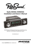
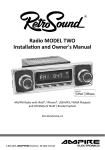
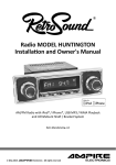
®
Retro Classic
Owner's & Installation Guide
RC-900C AM I FM Radio wi Front Aux input
and Infinimount Shaft/Bracket System
©
Copyright
2010 Retro Manufacturing, LLC
No text, illustrations, or format of this
manual in printed or electronic form
may be copied without written permission
from Retro Manufacturing, LLC or any of its subsidiaries.
All Rights Reserved.
Retro Manufacturing
5785 Waco Street
Chino, California 91710
Phone: 909·364·1372
Fax: 909·364·8670
www.retrosoundusa.com
Version 2.0
FEB 2010
•
Thank you for your purchase of our Retro Classic Radio! We hope it will provide
you with years of enjoyment. Below are some features of this unit:
•
•
•
•
•
•
•
LCD Display wI enhanced viewing angle & daylight compatible
AM/FM PLL tuner wI 30 presets & RDS
50W x 4 RMS 100W X 4 MAX POWER (Integrated amplifier)
2 pair RCA pre-amp outputs to add external amplifiers
Patent Pending INFINIMOUNT adjustable shaft & bracket system
Front aux input; plug in any MP3 player or other portable device, (cell phone, etc)
Adjustable faceplate angle; allows mounting of faceplate display to virtually any dash
This equipment has been tested and found to comply with the limits for a Class B device,
pursuant to Part 15 of the FCC Rules. These limits are designed to provide reasonable
protection against harmful interference in a residential installation. This equipment
generates, uses and can radiate radio frequency energy, and, if not installed and used in
accordance with instructions, may cause harmful interference with radio
communications. However, there is no guarantee that radio interference will not occur in
a particular installation. If this equipment does cause harmful interference to radio or
television reception, which can be determined by turning the equipment off and on, the
user is encouraged to consult the dealer or an experienced radio/TV technician for help.
You are cautioned that any changes or modifications not expressly approved in this
manual could void your authority to operate this equipment.
• Avoid installing the unit where it would be subject to high temperatures such as in
direct sunlight or a hot air stream from the heater or where it would be subject to dust,
dirt, or excessive vibration.
• Parking your car in direct sunlight will result in a temperature rise. Do not turn on the
unit if the temperature inside the car is very high. Always cool down the unit before
usage.
• If the unit does not turn on, check the connections first. Then, check whether the
fuse in your vehicle's fuse box is blown and check the fuse at the unit's wiring
harness.
• Carefully read this manual before using the unit. If you encounter any problems that
are not covered in this manual, please consult the dealer where you purchased the
unit or the dealer nearest to you. You may also email us at:
[email protected]
••
•
•
Page Number
Welcome, Warning & Precautions
Table of Contents
Installation & Use Warnings
Location of Controls, Remote, Connectors, etc
What's in the Box
Preparing to Install Your Unit.
Retro Classic Specifications & Dimensions
Using Your Unit
Setting the Clock
Turning the Unit On/Off
Volume Adjustment
Selecting Your Listening Source
Adjusting the Sound Properties
Special Modes of Operation/Sub Menu
About RDS/ Using RDS functions
Selected Source Mode: Radio
Selected Source Mode: Auxiliary Input.
Limited Warranty
1
2
3
4-6
7
8-14
15
16-22
16
16
16
16
17
18-19
20-21
22
22
23
Observe the following warnings when using
this unit.
OThe driver should neither watch the display nor
operate the system while driving.
Watching the display or operating the system will distract
the driver from driving safely and can cause
accidents. Always stop the vehicle in a safe location and use
the parking brake before watching the display or operating
the system.
OUse the proper power supply.
This product is designed for operation with a negative
grounded 12 V DC battery system. Never operate this product
with other battery systems, especially a 24 V DC battery
system.
OKeep batteries and insulation film out of reach of
infants.
Batteries and insulation film can be ingested, so keep them
out of the reach of infants. If an infant ingests a battery or
insulation film, please seek immediate medical.
OProtect the radio.
Do not insert any foreign objects into the slot of this unit.
000 not disassemble or modify the unit.
Do not disassemble, modify the unit or attempt to repair the
product yourself. If the product needs to be repaired, consult
your dealer or Retro Manufacturing directly.
000 not use the unit when it is out of order.
If the unit is out of order (no power, no sound) or in an
abnormal state (has foreign objects in it, is exposed to
water, is smoking, or smells), turn it off immediately and
consult your dealer.
OThe remote control unit should be loose in the
car,
If the remote control unit is loose in the car, it could fall on the
floor while driving, get wedged under the brake pedal, and lead to
a traffic accident.
ORefer fuse replacement to qualified service personnel.
When the fuse blows out, eliminate the cause and have it
replaced with the fuse prescribed for this unit by a qualified
service technician. Incorrect replacement of the fuse may lead
to smoke, fire, and damage to the product.
Observe the following cautions when using this
unit.
OKeep the sound volume at an appropriate level.
Keep the volume level low enough to be aware of road and
traffic conditions while driving.
000 not insert or allow your hand or fingers to be
caught in the unit.
To prevent injury, do not get your hand or fingers caught in
moving parts or in the disc slot. Especialiy keep infants from
doing so.
Observe the following cautions when installing.
Refer wiring and installation to qualified service
personnel.
Installation of this unit requires special skills and experience.
For maximum safety, have it installed by your dealer.
Retro Manufacturing is not liable for any problems resulting from
your own installation of the unit. Please be sure to follow our
instructions carefully before attempting installation
Follow the instructions to install and wire the product.
Not following the instructions to properly install and wire the
product could cause an accident or fire.
Take care not to damage the leads.
When wiring take care not to damage the leads. Prevent
them from getting caught in the vehicle chassis, screws, and
moving parts such as seat rails. Do not scratch, pull, bend or
twist the leads. Do not run them near heat sources or place
heavy objects on them. If leads must be routed around sharp
metal edges, protect the leads by winding them with vinyl
tape or similar protection.
Use the designated parts and tools for installation.
Use the supplied or designated parts and appropriate tools
to install the product. The use of parts other than those supplied
or designated may result in internal damage to the unit.
Faulty installation may lead to an accident, a malfunction or
fire.
ODisconnect the lead from the negative H battery
terminal before installation.
Wiring and installation with the negative (-) battery terminal
connected may cause electrical shock and injUry due to a
short circuit.
Some cars equipped with the electrical safety system have
specific procedures for battery terminal disconnection.
FAILURE TO FOLLOW THIS PROCEDURE MAY LEAD TO THE
UNINTENDED ACTIVATION OF THE ELECTRICAL SAFETY
SYSTEM RESULTING IN DAMAGE TO THE VEHICLE AND
PERSONAL INJURY OR DEATH.
ONever use safety-related components for installation,
grounding, and other such functions.
Do not use safety-related vehicle components (fuel tank,
brake, suspension, steering wheel, pedals, airbag, etc.) for
wiring or fixing the product or its accessories.
Olnstalling the product on the air bag cover or in a
location where it interferes with airbag operation is
prohibited.
Oln the case of installation to an airbag-equipped car,
confirm warnings and cautions of the vehicle manufacturer
before installation.
OCheck for piping, gasoline tank, electric wiring, and
other items before installing the product.
If you need to open a hole in the vehicle chassis to attach or
wire the product, first check where the wire harness, gasoline
tank, and electric wiring are located. Then open the hole
from outside if possible.
QNever install the product in a location where it interferes
with your field of vision.
ONever have the power cord branched to supply other
eqUipment with power.
OAfter installation and wiring, you should check the
normal operation of other electrical equipment.
The continuation of their use in abnormal conditions may
cause fire, electrical shock or a traffic accident.
OMake sure the leads do not interfere with driving or
getting in and out of the vehicle.
Olnsulate all exposed wires to prevent short circuiting.
OThis unit is designed for use exclusively in automobiles.
000 not operate the unit for a prolonged period with
the engine turned off.
Operating the audio system for a long period of time with the
engine turned off will drain the battery.
000 not expose the unit to direct sunlight or excessive
heat.
OtherNise these wi!! raise the interior temperature of the
unit, and it may lead to smoke, fire, or other damage to the
unit.
000 not use the product where it is exposed to water,
moisture, or dust.
Exposure of the unit to water, moisture, or dust may lead to
smoke, fire, or other damage to the unit. Make especially
sure that the unit does not get wet in car washes or on rainy
days.
4.
Please review this section for quick reference, as it contains information on the location of controls and
basic operations. For sBecific d,rWi1s 0~~~7~~~:J&~{i~g;li~g!;.gl*~.~*r~t*r}g.m~table of contents.
O
POWER on/off: Press the left center knob to turn the unit on. Press and hold the left center knob for
2 seconds to turn the unit off. Turning the center left shaft controls the volume attenuation up and
down. Note: Volume range is 0 - 40(Min/Max).
~ Pressing the left center shaft inward activates the SEL (Select) function. Press this repeatedly to
,,~ cycle through the DSP (Digital Signal Processing) EO, Bass, Treble, Balance & Fader function(s).
C) Pressing the "1" button allows for selection of a radio preset.
e
Pressing the "2" button allows for selection of a radio preset.
4i) Pressing the "3" button allows for selection of a radio preset.
(;) Pressing the "4" button allows for selection of a radio preset.
fI Pressing the "5" button allows for selection of a radio preset.
f3 Pressing the "6" button allows for selection of a radio preset.
~AUX Input(s): Allows you to plug in any device with a headphone 1/8"(3.5mm) output, directly into
W
the front face of the Model One (Example: Ipod, CD player, Satellite, Mp3 player, etc). Use the
MODE button to select Aux 1 (Front Aux input).
@ Turning the right center knob to the right & left allows you to tune to the next or previous Am/Fm
frequency.
~ Pushing in the right center knob for 2 seconds, will allow you to access the sub menu system
where you can adjust loudness on/off, beep on/off, US/EU tuning, stereo/mono, OX (distant)/Iocal
tuning volume on default level. Pushing the right center knob for one second will
toggle the am/fm tuner mode from Auto to Manual.
Please review this section for quick reference, as it contains information on the location of controls and
basic operations. For specific details~~~~~~~ri~j~~i~i~~i~tn~J~j~tr*nmj~~~,~~~.JQ.~~abl~of contents.
~ T/F Button: Use this button to view the clock, and toggle through various modes. Press and hold to
set the clock in conjunction with the left control shaft.
~ MODE Function: Press this button to switch between all modes of operation, Radio/AUX-In 1. This
button also can access the TA (Traffic Announcement function of the RDS tuner.)
~ BAND Function: Press this button to switch between 3 FM BANDS (FM 1/FM 2/ FM 3) 2 AM
~ BANDS (AM-1 AM-2); 30 PRESETS TOTAL. To save your preset, simply hold the preset button
down, listen for the confirming beep or blinking of the preset. Your desired preset will be then
saved.
~ Backlit LCD Display Window
Installation Notes:
REAR View of Retro Classic RC-900C
Internal Amplifier
Heatsink
Threaded mount for metal backstrap
(included) used for rear support of
main b o d y ' · · · · ·
External Antenna
Input
4 RCA outputs
for adding external
amplification
Female ISO wire harness connector
w/1 male power/ground harness
& 1 male speaker lead harness
k- )~~~~J~::~
:,:,,;.'<,'''';:'
What's in the box:
o
(1) Retro Classic Unit*
~ (2) Infinimount Brackets
C) (2) Infinimount Shaft System
e
(1) Metal backstrap wI hardware, used to secure main unit behind dash
~ (2) ISO Wiring harness to connect to Retro Classic
<D (mise) Screws, washers & parts to mount Infinimount shafts & brackets
*Note: Item # 1 is not shown above,
but is included in the box
8,
,------------------------------,
: PLEASE NOTE THAT THIS UNIT REQUIRES +12V :
I
TO BOTH THE RED & YELLOW WIRES,
I
OTHERWISE THE UNIT WILL NOT OPERATE.
I
I
:
CALL US OR EMAIL US IF YOU HAVE
:
I
QUESTIONS!
I
,------------------------------,
Familiarize yourself with the Retro Classic wiring harness (Note: There are
2 plug connectors: Plug "A" which contain power/ground connections & "8"
which contains the speaker leads)
Retro Classic RC-900C
Frequency Range:
FM 87.5-107.9 MHZ
AM 530-1710 KHz
Wiring Diagram
BACK OF RADIO
ANTENNA INPUT
~:::t=j~.J1
Note: Yellow & Red
wires must be connected
to +12V for radio to operate
RED
~_~rO RCA LINE OUT
IGNITION I ACC (CONNECT TO +12VI
L.o
BLUEIWHITE - - - ~
(REMOTE/AMP TURN ON)
BLUE
(POWER ANTENNA)
FRONT
LEFT
SPEAKERS
4 OHM
REAR (BLACK)
RCA LINE OUT
GREY (FRONT)
+
WHITE (+)
GREY (+)
+
GREY/BLACK
-
PURPLE (+)
+
PURPLE/BLACK
-
FRONT
.,IU-------I
- WHITE/BLACK (-)
+
GREEN (+)
REAR
RIGHT
SPEAKERS
40HM
REAR
-GREEN/BLACK (-)
Note: This radio is designed for use in vehicles with a 12 volt negative ground system
Installation Notes:
To prevent damage to the unit, do not connect the power connector
until you have completed the wiring process.
This is a 12 Volt negative-ground ONLY radio. If you have a positiveground, or a 6-volt system, you need to either convert to 12 volts or
purchase a separate inverter that would step up the voltage to 12 volts.
Please note that the inverter needs to be rated at 5 amps or higher
in order for your unit to operate properly.
Find the Infinimount shafts & brackets (2 of each enclosed)
X2
Assemble the Retro Classic unit's Infinimount bracket and shaft system
using the supplied screws and shaft nuts.
Due to the flexible installation variations this system offers, in order
to match the Infinimount shaft & bracket system to the proper shaft width
of your vehicle, simply measure the distance between your existing shaft
holes center to center. Then mount the shaft system to the bracket using
suppled shaft nuts and shaft mounting guide, and finger tighten to prepare
for the final installation (see figure A below). Once you are sure of proper width,
then tighten prior to final installation. Be sure to plug the shafts into the side of
the main unit to activate the shaft-control functions see fi ure B below).
B.
A.
Mount Shaft
to Bracket
Plug Shaft into
Side of Main Unit
10.
•
.....
If
Prepare to set up your vehicle-specific kit
(Optional 67-72 GM Truck bezel shown as an installation example)
Once shafts are lined up to the shaft openings on the vehicle-specific
faceplate adapter, use a nut and washer to hold the faceplate in place on the
shafts so the Retro Classic's face is flush with the opening of the faceplate (see
photos below). NOTE: Modifying or cutting the radio's brackets will not void your
warranty, this is what our radio is designed for.
Use supplied nuts & washers
to align bezel onto shaft.
Adjust nut height to allow bezel/faceplate
to be flush in your dash. Note, with this bezel, the area around the
radio face (chrome or black) mounts from behind your dash.
·1IIlIIlI
Vehicle-specific adapter & Retro Classic
radio face should be flush for professional appearance
Tighten shaft nuts and make sure that shaft depth works with
your dash configuration; the Retrosound Infinimount bracket shaft and bracket system
are extremely adjustable and care should be taken to ensure proper final fit
for the perfect installation.
11,
• •
Below, The final result!:
67-72 GM Truck bezel shown installed in the vehicle's dash, note that the radio face is flush with the bezel in the
dash for a professional looking installation. Getting the unit to fit perfectly into your dash is probably the most
difficult portion of the install. Patience and persistence is the key. If you still have problems, please send us an
email at~lJ.P.P!.)Jt@r~t[Q_~_QlJlJ(;!_lJ§~.<::Qmor give us a call at: 909-364-1372.
If you still have difficulties during your installation, we strongly recommend that you take your vehicle to a high
quality car audio installation shop or classic car specialist.
•
41
The Retrosound Model One is available with an optional set of metal
knobs and a faceplate (for the front of the dash) or bezel (mounts from
behind the dash) that fits around the control face of your Model One/Apache
or Retro Classic radio(s). Please consult us at [email protected]
regarding a universal or vehicle specific faceplate/bezel & knob kit for your car.
Below is a Retro Model One shown with an optional 67:-68 Camaro
faceplate & Chrome Metal k n o b s . / ' ) "
"I
.$~«:>~;.
Optional:
67-68 Camaro Faceplate shown above
Below are examples of some of the available dash bezels and faceplate
adapters available:
Optional:
68-85 VW/Porsche/Jaguar/BMW faceplate
(mounts on top of the dash) This solution
shown with our exclusive all metal chrome
euro style knobs
Optional:
70-72 Chevelle bezel. (mounts from
behind the dash) This solution shown
with our exclusive all metal GM style black
and chrome metal knobs
Optional:
59-67 Cadillac dash bezel, notice the shafts have been
placed on the left side of the radio, something no other
radio can do out of the box. Your Retrosound
Radio is capable of so many amazing installation
possibilities, they're only limited by your
imagination!
Visit our website to see more vehicle specific solutions
www· rl:1trQ~Q-,'!.mjl,l~~,~9.m
NOTE: The following installation option is for advanced knowledgeable custom
installation specialists. The Retro Classic control face is removable
to allow for unique angled installations, canted angles, upside-down mounting
and other unique configurations limited only to your installation skills. Below
is a photo illustrating what the unit looks like with the control face removed,
connected by a ribbon cable from the body of the main unit to the radio's control
face. (There is about 4.5" of cable length from the body to the radio control face).
Apache Radio wI
advanced removable
faceplate for unique applications
i:~"
;~····4.5"
After preparing for your installation and understanding your needs,
proceed to install the unit and connect the wiring, and make sure
you use the metal back strap to support the main body of the the unit from the
rear.
Install metal backstrap behind
unit for rear support of the main body
•
14.
Metal Knob Install Guide
Sometimes the Retrosound Shafts need to be adjusted to allow you to
mount our metal knobs to the shafts. Once your radio is installed
follow the steps below to ensure a proper knob fit.
04
I •
2.
For the rear-knob, simply insert
a biade screwdriver diagonaiiy to
slightly spread apart the secondary
back-knob position to allow the
rear knob to fit snugly.
For the front-knob, use a pair
of needle nose pliers and GENTLY
crimp the front-knob prongs closer
together. Please use caution not
to make these too tight, then mount
the front-knob, and you're done!
Final Result! Modern Sound for your Classic!
3.
15,
Tuner Section
Specs
FM
Tuning Range (Eu & US Tuning Capable) wi ROS
Antenna Terminal
Usable Sensitivity
Selectivity
Signal to noise Ratio
Harmonic Distortion @ 1 kHz
Separation
Frequency Response
87.5-107.9MHz
Extemal Antenna Connector
12.5 dBf
75 dB @ 400kHz
62 dB (Stereo), 67 dB (Mono)
0.8% (stereo), 0.5% (monaural)
32 dB @ 1kHz
30-16,000 Hz
AM (Eu & US Tuning Capable)
Tuning Range
Antenna Terminal
530-1710 kHz
Extemal Antenna Connector
General
Dimensions (Radio face only)
Dimensions (Radio body)
3.5"W x 1.5" H x 1.05" 0
3.96"W x 198"H x 4.30"0
Power Requirements
Current Consumption
Current Consumption
Output Power (@ 14.4 V @ 4 ohm @ 1% THO)
Output Impedance
Low Level Output (4 Channels)
AUX input (Rear)
AUX input (Front)
10.5-14.4V
Max. 15A
<3.5 mA
50x4w RMS 100x4 Max power
4-8ohm
2.85V
2 V 16 kG
500 mV /6 kG
All Unit Specs Are Subject To Change without notice
Unit Dimensions
8" Length Infinimount
Connection Cable
1.5"H
. ;'f:i
__ ._.~---.-.~ (Radio Face)
.0__ "-'---
-_ •••
-~
IN
~- II II II ..............
..•••••••• 3.5"W
(Radio Face)
16.
Setting the Clock:
Press the TtF Button on the face of the unit when the unit is turned on.
Press and hold the T1F button. When the clock is seen on-screen blinking, use the left
shaft center knob, and turn knob right or left to adjust hours (note: AM & PM is
adjusted by changing hours). Press the left shaft center knob to select minutes,
then turn left or right to adjust. Press TtF button to store the clock settings.
(Note: When EU tuning mode selected, militaryt24 hour time mode will be activated).
Once the time is set, pressing the TtF button will activate the clock mode.
Press and hold to activate
clock setting mode
~
Turning The Unit On/off:
Press the Left center knob to turn the unit on. Look for "RETROSOUr:O" on power up.
Press and hold the left center knob for 2 seconds to turn the unit off. The LCD display
will show "G0008=:E" for your confirmation.
Volume Adjustment:
Turning the center left shaft left or right controls the volume attenuation up and down function.
Note: Volume range is 0-40, factory default is set at 16. Use the included remote to activate "mute"
function.
Select Your Listening Source(s):
MODE Function, Press this button to switch between all modes of operationRadio fAux in 1 fAux in 2 f USBfSD-MMC
01 ,\/ II'"
I fL'/\ II If
iiil_---·········
.A
1
-7 .
Adjusting the Sound Properties:
The Retro Classic radio has many sound adjustment modes to help you tailor the radio to
your preference. To access these modes of adjustment, press the left knob (SEL) in and turn the
knob to the right or left to adjust. Then press SEL again to cycle through the choices.
When you have completed your adjustments, simply stop adjusting the mode and it will revert
to your current setting. Below are photos of the various sound adjustment modes available
in all playback modes, Radio, Aux1.
The CLASSIC DSP setting offers
sonic adjustments that lend themselves
to Classical Music.
When you first access the SEL menu,
DSP is off. Turn the left shaft knob right
to cycle through the presets or press
SEL to move to the bass & treble settings.
The DSP OFF setting offers
no bass or treble adjustment.
The POP DSP setting accentuates
the bass and treble settings. This is
suitable for bass heavy popular music.
The ROCK DSP setting accentuates
the treble settings. This is suitable
for Rock Music
The bass adjustment function allows you to
boost or cut the low frequencies from -7 to +7.
The Balance adjustment function allows you to
adjust or pan the stereo sound from the left or
right. This is helpful to compensate for the
position of the driver in relation to the speaker
location. Adjustment range is 0-10 left or right
speakers.
The Fader Control allows you to fade the sound
from the front pair of speakers to your rear
pair of speakers. Adjustment range is 0-10 front
or rear speakers.
The treble adjustment function allows you to
boost or cut the high frequencies from -7 to +7.
18.
To Activate the LOUDNESS function from the Sub Menu, press the center right shaft "SEL" button and hold it for
2 seconds. Then turn the shaft control right or left to toggle the LOUD function ON or OFF. This function boosts
bass & trebie at iow iistening voiume and should be turned off at higher volumes. You will know this function is active
when you see "LOU" lit up on your display.
SUB-MENU FUNCTION: BEEP ON/OFF
To modify the audible confirmation beep on or off (factory default is "BEEP ON"),
press and hold the SEL (right center shaft knob). Repeatedly press the right center shaft to scroll through the
sub menu and turn the knob to the right to turn the confirmation beep to "BEEP OFF".
SUB-MENU FUNCTION: US/EU RADIO TUNING
The Retrosound Model One has the capability to receive AM/FM broadcast frequencies in other
countries. To modify the default setting (USA) to EUR (Europe), press and hold the SEL
(right center shaft knob). Repeatedly press the right center shaft button to scroll through the sub menu and turn
the knob to the right, on screen you will see "AREA USA". Turn the knob to the right to select
AREA USA or AREA EUR. To confirm the change, let the sub menu revert to your tuner. You will see
your selected mode, either AREA USA OR AREA EUR. Press SEL to move to the next function desired, or
don't press anything and the menu will revert to the current source display.
IMPORTANT: When switching the tuner to BND EUR mode, your STORED radio presets will be erased
and the clock will change to military /24 hour time. Also in EUR tuning mode, the "AF" RDS function
(as a default) will be active, and the unit will search for the next strongest station when the one you're listening
to gets weak (FM only).
SUB-MENU FUNCTION: STEREO/MONO
When listening to the AM/ FM tuner, you can access the stereo/mono Sub Menu system. Press and hold the SEL
(right center shaft knob). Repeatedly press the center shaft to scroll through the sub menu and turn the
knob to the right to select between Stereo/Mono operation. Selecting between these functions can aid in
listening to weak FM radio stations that keep switching between Stereo & Mono modes.
Selecting mono in this case will prevent this, so you can reliably listen to the station.
SUB-MENU FUNCTION: LOCAL / OX
When listening to the FM tuner, you can access the localldx Sub Menu system. Press and hold the SEL
(right center shaft knob). Repeatedly press the center shaft to scroll through the sub menu and turn the knob
to the right to select between Local/ DX (Distant) operation. Selecting between these functions can aid in
listening to weak FM radio stations or compensate for stations that have too strong of a signal.
SUB-MENU FUNCTION: VOL AOJNOL LAST
From any mode you can access the vol adj/vollast Sub Menu system.
Press and hold the SEL (right center shaft knob).
Repeatedly press the center shaft to scroll through the sub menu, turn the knob to the right to select
VOL ADJNOL LAST operation. Factory default is VOL LAST (this mode maintains the last volume the radio
was at when you turned it off). When you select VOL ADJ mode, you can set the default turn-on volume
at any level you want, no matter what the volume level was when you last turned off the unit.
WHAT IS RD5?
flJJRo'!1~5.
RDS stands for Radio Data System. RDS tuners can automatically tune in stations according to the style of
music (or talk) they broadcast. Some RDS tuners can even break in with traffic alerts or emergency broadcasts.
RDS enables your receiver to display text messages (usually call letters and format info) that many
FM stations include on a subcarrier signal within their normal broadcast signal.
How to use RDS on your Retrosound Radio
The RDS function is always active, and if the FM station you are listening to is broadcasting RDS information,
the radio station call letters, song info, artist info and other messages will appear. Please note that not all
FM stations use RDS. The standard has been around for well over 15 years.
How to use the PTY function when in the AREA USA tuner mode
RDS has a function called PTY (Program Type). This coding of up to 31 pre defined program types allow
you to find similar programming by genre. When the tuner searches for this desired programming type,
the tuner will study all strong FM stations to see what programming type they are broadcasting.
If the programming type is found, the radio will select it.
To use this function, press and hold BAND button for 2 seconds. Use the Preset buttons 1-6 to choose from
10 different program categories (2 per preset), then hold the BAND button for another 2 seconds to access
another bank of 10 program categories. Once the program type has been selected, the tuner will search
all available FM stations for a station broadcasting the selected program category. Example, if you're looking
for COUNTRY stations: PRESS AND HOLD BAND FOR 2 SECONDS, THEN PRESS AND HOLD FOR ANOTHER
2 SECONDS, PRESS PRESET # 3 AND TOGGLE BETWEEN ADLT_HIT I COUNTRY, BY PRESSING THE PRESET
# 3 BUTTON. Your screen will look like this:
SEARCHING FOR COUNTRY STATIONS
PRESS AND HOLD "BAND" ONCE FOR 2 SECONDS TO ACCESS THESE PROGRAM TYPES:
1# Preset: ROCKlCLS_ROCK
4# Preset: NOSTALGIA/JAZZ
2# Preset: SOFT- RCKITOP - 40
5# Preset: CLASSICLIR B
3# Preset: OLDIES/SOFT
PRESS AND HOLD "BAND" ONCE AGAIN FOR ANOTHER 2 SECONDS TO ACCESS THESE PROGRAM TYPES:
1# Preset: NEWS/INFORM
4# Preset: LANGUAGE/REL_TALK
2# Preset: SPORTS/TALK
5# Preset: PERSNLTY/PUBLIC
3# Preset: ADLT_HIT/COUNTRY
6# Preset: COLLEGEIWEATHER
• •
How to use the PlY function when in the AREA EUR tuner mode
RDS has a function called PTY (Program Type). This coding of up to 31 pre defined program types allow
you to find similar programming by genre. When the tuner searches for this desired programming type,
the tuner will study all strong FM stations to see what programming type they are broadcasting.
If the programming type is found, the radio will select it.
To use this function, press and hold BAND button for 2 seconds. Use the Preset buttons 1-6 to choose from
10 different program categories (2 per preset), then hold the BAND button for another 2 seconds to access another
bank of 10 program categories. Once the program type has been selected, the tuner will search
all available FM stations for a station broadcasting the selected program category. Example, if you're looking
for NEWS stations: PRESS AND HOLD BAND FOR 2 SECONDS, THEN PRESS AND HOLD FOR ANOTHER
2 SECONDS, PRESS PRESET # 1 AND TOGGLE BETWEEN NEWS/AFFAIRIINFO, BY PRESSING THE PRESET
# 1 BUTTON. Your screen will look like this:
SEARCHING FOR NEWS STATIONS
PRESS AND HOLD "BAND" ONCE FOR 2 SECONDS TO ACCESS THESE PROGRAM TYPES:
1# Preset: POP M' ROCK M
4# Preset: JAZZ' COUNTRY
2# Preset: EASY M' LIGHT M
5# Preset: NATIONAL M , OLDIES
3# Preset: CLASSICS' OTHER M
6# Preset: FOLK M
PRESS AND HOLD "BAND" ONCE AGAIN FOR ANOTHER 2 SECONDS TO ACCESS THESE PROGRAM TYPES:
1# Preset: NEWS' AFFAIR 'INFO
4# Preset: WEATHER' FINANCE' CHILDREN
2# Preset: SPORT' EDUCATIO , DRAMA
5# Preset: SOCIAL' RELIGION' PHONE IN
3# Preset: CULTURE' SCIENCE' VARIED
6# Preset: TRAVEL' LEISURE' DOCUMENT
AF FUNCTION: (AVAILABLE ONLY IN AREA EUR TUNER MODE)
in EUR tuning mode, the "AF" RDS function (as a default) will be active. The unit will search for
the next strongest station, when the one you're listening to gets weak (FM only). You can turn
this function off by accessing the right shaft sub menu. When in AREA EUR tuning mode,
this function appears, and you can turn it on or off in the sub menu. (default is ON).
TA FUNCTION: (AVAILABLE IN US & EU TUNING MODES
TA or "Traffic Announcement" is another RDS function that allows FM stations to broadcast traffic
announcements that scroll across the screen and also broadcast audible traffic alerts to your radio.
To access this mode, press and hold the "MODE" button to toggle this "TA" function ON or OFF.
•••.
:~::
..
.•....
22.
Selected Source: Radio
Once you've selected the radio function, you can start storing your presets or tuning to
your preferred station.
Press "BAND" to
select FM1,2,3 or AM1,2 - - - - - .
for a total of 30 Presets
To save a preset, tune to the station using the right shaft knob, then choose the preset number you
wish to assign to that station. Press and hold the button. Listen for a confirming beep, and now
you have saved that preset. NOTE: turning the right shaft knob to the right or left will allow the
tuner to select the next or previous strong station. This is known as the SEEK or "AUTO" function.
To manually tune, press the right shaft knob in and you will see "MANUAL" appear in the center
of your screen (see photo below). This will allow you to manually tune into any station
you want, strong or weak.
Band Preset
Indicator (shows you the
Preset # you have assigned
to the preset button)
When a strong FM station
is selected the
indicator will light up
aD
Selected Source: AUXILIARY INPUT 1 (FRONT OF RADIO)
Plug in your external music source using a 3.5mm (1/8") connector.
An example of an external source would be a portable CD player, mini disc player, portable
cassette recorder, Ipod, Mp3 player. Anything with an analog stereo headphone jack can be
connected to this input.
(see photos below).
Connect your 3.5 mm (1/8") stereo
headphone connector to the AUX
in port on the front of the Retro Classic
'-==.==....:::::=,:
.•.•.•.•.•.••.:• .•:.:. •::.•::.•:••••: ~
••
;•••••
; ; .;,; ;,; ~
.• . •. • •.•.• . •. ~
AUX IN 1
(FRONT PANEL AUX IN)
.
23,
LIMITED WARRANTY
If your product does not work properly because of defects in materials and workmanship RetroSound a division of Retro
Manufacturing, LLC (collectively referred to as "the warrantor") will, for the length of the period indicated in the chart
below, which starts with the date of original purchase ("warranty period"), at its option either
(a) repair your product with new or refurbished parts, or (b) replace it with a new or refurbished product. The decision to
repair or replace will be made by the warrantor.
CATEGORIES
Retro Classic Radio
Speakers
Accessories (Remotes, cables, etc)
PARTS
One (1) Year
One (1) Year
90 Days
LABOR
One (1) Year
One (1) Year
90 Days
During the "Labor" warranty period, there will be no charge for labor. During the "Parts" warranty period, there will be no
charge for parts. You must carry in or mail in your product prepaid during the warranty period. If batteries are included,
they are not warranted. This warranty only applies to products purchased and serviced in the United States, Alaska,
Hawaii or Puerto Rico. This warranty is extended only to the original purchaser of a new product which was not sold "as
is". A purchase receipt or other proof of the original purchase date is required for warranty service.
To handle a warranty issue, contact us at 909-364-1372 or email us at [email protected] and get a Return
Authorization number. All returns and warranty issues must receive a Return Authorization (RA) number. Any product
received without a RA number will be refused. Once a number is issued, send the product to this address:
Retro Manufacturing, LLC
5785 Waco Street
Chino, California 91710
Phone: 909-364-1372
Fax: 909-364-8670
LIMITED WARRANTY-LIMITS AND EXCLUSIONS
This warranty ONLY COVERS failures due to defects in materials and
workmanship, and DOES NOT COVER normal wear and tear or cosmetic
damage. The warranty ALSO DOES NOT COVER damages
which occurred during shipment, failures which are caused by products
not supplied by the warrantor, failures which result from accident,
misuse, abuse, neglect, bug infestation, mishandling, misapplication,
alteration, faulty installation, set-up adjustment, maladjustment
of consumer control, improper maintenance, improper antenna,
inadequate signal reception or pickup, power line surge, improper
voltage supply, lightning, modification, commercial use (such as
use in hotels, offices, restaurants, or other business uses) or rental
use of the product, or service by anyone other than the technician
from Factory Service center or other authorized service centers, or
damage that is attributable to acts of God.
THERE ARE NO EXPRESS WARRANTIES EXCEPT AS LISTED
UNDER "LIMITED WARRANTY COVERAGE". THE WARRANTOR IS
NOT LIABLE FOR INCIDENTAL OR CONSEQUENTIAL DAMAGES
RESULTING FROM THE USE OF THIS PRODUCT, OR ARISING OUT
OF ANY BREACH OF THIS WARRANTY. (As examples, this excludes
damages for lost time, cost of having someone remove or re-install
an installed unit if applicable, travel to and from the sevicer, and loss
of media, data or other memory cOlltents. The items listed are not
exclusive, but are for illustration only.) ALL EXPRESS AND IMPLIED
WARRANTIES, INCLUDING THE WARRANTY OF MERCHANTABILITY,
ARE LIMITED TO THE PERIOD OF THE LIMITED WARRANTY.
Some states do not allow the exclusion or limitation of incidental or
consequential damages, or limitations on how long an implied warranty
lasts, so the exclusions may not apply to you.
This warranty gives you specific legal rights and you may also have
other rights which vary from state to state. If a problem with this
product develops during or after the warranty period. you may contact
your dealer or service center.
®
Retro Classic
Owner's & Installation Guide
RC-900C AM I FM Radio wi Front Aux input
and Infinimount Shaft/Bracket System
©
Copyright
2010 Retro Manufacturing, LLC
No text, illustrations, or format of this
manual in printed or electronic form
may be copied without written permission
from Retro Manufacturing, LLC or any of its subsidiaries.
All Rights Reserved.
Note: The information enclosed in this installation guide is to be used as merely an outline to
assist you during the process of installation. This guide does not cover every installation
possibility, vehicle, or every aspect of the installation process.
Retro Manufacturing, LLC , Retrosound, or its subsidiaries, assume no responsibility for a
proper or improper installation. Every attempt has been made to make this installation guide
as informative as possible, and therefore may be updated from time to time. Please check our
website for the latest update. (www.retrosoundusa.com).
Version 2.0
FEB 2010