1
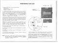
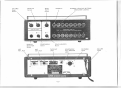
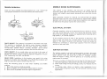
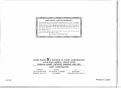
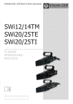
~ 00@muaJ [?[ill] ~®00000Doorn
0
W00 [f ~ ~(~Jc=~~ [ID I
TI~ ffi
c=J
ITmwooOU®u OO@@@Dw@u
TI i7 ~ llYlJ 00 ~ l iJ 00 [f ~ ~~[ID
c=J
~TI !2 llYIJ 00 ~
~00@· 0 TI ·aJ~
PLEASE READ BEFORE
USING THIS EQUIPMENT
1-•EALIShC ®
CATi. NO.
20-165
CUSTOM MANUFACTURED FOR RADIO SHACKgA DIVISION OF TANDY CORPORATION
Your PATROLMAN PR0-16A scanning receiver is a completely transistorized VHF / UHF superheterodyne receiver using dual-conversion
for the VHF bands and triple conversion for the UHF band. It is
capable of automatically scanning sixteen crystal-controlled channels. Some special features are: four ceramic filters, channel lock-out
circui"t, skipper circuit, AFC circuit for UHF band, scan delay circuit
(switchable) and AC or DC operation.
SPECIFICATIONS
SEMICONDUCTOR
COMPLEMENT:
It is designed for use in the narrow-band FM channels of public
service communications: VHF and UHF band police, fire, civil
defense, radio telephone, forestry and weather service, plus many
other industrial radio services and the 2-meter "HAM" radio band
(upper end). These and many other services share this band of
frequencies from 30 to 50 MHz, 148 to 174 MHz and 450 to 512
MHz.
.
FREQUENCY RANGE:
CHANNELS OF OPERATION:
FREQUENCY COVERAGE
(VHF):
The PR0-16A features both high sensitivity and selectivity and a
sophisticated circuit which includes 10.7 MHz and 445 kHz ceramic
filters to reduce or eliminate adjacent-channel or strong-signal interference. Such interference is often experienced when operating in
urban and metropolitan areas or where very strong and closely
placed signals are present.
(UHF):
SENSITIVITY:
SELECTIVITY:
An important engineering achievement, designed for practical applications, the PR0-16A is remarkably easy to use, yet its up-to-date,
complex circuit consists of 52 separate transistors (three of which
are Field Effect Transistors), six intergrated circuits (which incorporate the equivalent of hundreds of components), 66 diodes and 1
zener diode.
ADJACENT CHANNEL
REJECTION:
SPURIOUS REJECTION (VHF):
IMAGE REJECTION
(VHF):
(UHF):
VARIABLE SCANNING SPEED:
PRIORITY CYCLE RATE:
DELAY TIME:
MODULATION ACCEPTANCE:
AFC ACTION (UHF):
1.F. FREQUENCY:
This Receiver is designed to operate from either 120 volts AC or 12
volts DC Negative Ground. If it fails to operate, and there is no
clear reason for the failure, first check the "power" switch (part of
Volume control) . Also, before connecting the PR0-16A receiver to a
DC power supply, check the voltage polarity. Attempting to operate
the negative-ground PR0-16A from one of the rare positiveground
automotive or boat electrical. systems, or from a wrongly connected
battery, will at least blow a fuse. It may do further damage, so that
expensive and time-consuming repairs are necessary before the
PR0-16A can be used again. The Radio Shack warranty does not
apply to any damage caused by this, inadequate lightning protection, or other improper connections.
FILTER:
SQUELCH SENSITIVITY:
AUDIO POWER:
CRYSTAL REQUIREMENTS:
BUILT-IN SPEAKER:
POWER REQUIREMENTS:
WARNING: TO PREVENT FIRE OR SHOCK HAZARD, DO NOT
EXPOSE THIS RECEIVER TO RAIN OR MOISTURE.
-2-
52 transistors, 6 integrated circuits
and 67 diodes
30-50 MHz/ 148-174 MHz and
450- 512 MHz
Sixteen-as determined by any one
of 16 crystals operating in the
frequency range
6 or 8 MHz for maximum sensitivity
(40 MHz± 3 MHz)
(153 MHz± 4 MHz)
30 MHz for maximum sensitivity
(480 MHz± 15 MHz)
Betterthan 1µVfor20dB quieting
±13.5 kHz, -6 dB
±25 kHz, -50 dB
65 dB (25 kHz)
Greater than 50 dB
Greater than 35 dB
Greater than 20 dB
10 to 20 channels/second
0.8 to 1.5 seconds
1.5 to 3 seconds
±7 kHz
Greater than ±4 kHz
44 MHz (UHF Band only)
10.7 MHz and 455 kHz
Ceramic filter
(10.7 MHz and 455 kHz)
Variable from less than 1 microvolt
2 watts maximum
Standard HC-25/U, 3rd overtone
2Y:1" x 4"(6.3x10 cm) oval speaker
ACc_ 120 voltsJ60Hz,12 watts, max.
DC-12-15 volts Negative Ground
only ( 10 watts maximum)
PREPARING FOR USE
BOTTOM OF CASE
To use your PR0-16A, you must do three things:
Connect power
I nstal I from 1 to 16 crystals
Connect an antenna
To make a quick check, you can just connect the Line Cord to a
source of 120 volts, 60 Hz, AC power. If you intend to use a 12 volt
source, you must connect the 12 volt DC power plug wires as noted
later on under "Mobile Installation". With an antenna connected and a
crystal installed, turn the Receiver on by rotating VOLUME
clockwise. Rotate SOUE LCH maximum counterclockwise. You
should hear a "rushing" sound in the speaker.
Crystals are not included with your PR0-16A because the frequencies
are so numerous. The frequencies used in your part of the country will
be different from those used in other areas. Order the crystals you
want from your Radio Shack store - specify the model number of this
unit and the frequency you want to receive.
CH-1
0~1GH)
I -,,--~-, I
Remove the two Screws from the Crystal Compartment Cover
(bottom of cabinet) to expose the crystal sockets and program
switches. Provision is made to install 16 crystals; the program switch
position can be used to obtain either VHF(L), VHF(H) or UHF .
PO SITION
L H U
II
For UHF crystals, position the program switch to UHF (Marked "U"
on printed circuit board).
For VHF(H), set the program switch to VHF (Marked "H" on printed
circuit board).
For VHF(L), set the program switch to VHF (Marked "L" on printed
circuit board) .
I
I
I
I
I
CH -9
r~l~SITION
FR ONT SIDE
CH-9,
In the example shown channel 1 will have a VHF(H) crystal and
channel 9 will have a UHF crystal.
Ask the manager of your Radio Shack store w hat th e most popula r
and active channels are in you r are a. He will be glad t o advise you.
NOTE: If you have a channel that you are particularly interested in,
put the crystal for that channel into Channel 1 position
(PRIORITY ). Refer to OPERATION section for details on
the function of PRIORITY.
Since crystal frequencies must be extremely accurate and crystals
should be matched for specific units, we recommend you obtain
crystals for your Receiver onl y from Radio Shack. We can not be
responsible for the poor or improper operat ion of cryst als from
another manufacturer(s) .
-3-
CONTROL LOCATION AND FUNCTION
PRIORITY Button-will lock in channel 1 for priority reception over
any other active channel. Thus, when pressed in, if a signal comes on
this channel, the Receiver will automatically lock-in on it and will stop
scanning. When the signal ceases on this channel, the receiver will start
scanning once again.
OFF-VOLUME is the power switch and Volume control. When not in
use, rotate this control to the left to turn it off.
SQUELCH control is to eliminate annoying background noise
between signal transmissions. When properly set, Squelch will keep
the PR0-16A silent until a signal comes in on the channel(s) you are
listening to-then, the Squelch circuit will "open" and you hear the
signal.
VHF Antenna Jack-for VHF reception, connect an antenna to this
jack. Use an antenna such as Catalog Number 20-161 (indoo r operation).
MANUAL SELECTOR Button-when the SCAN/MANUAL button is
in the MANUAL position (out), use this button to advance the
Receiver to the next channel in sequence . Each time you press this
button, the Receiver will advance just one channel.
UHF Antenna Jack-connect an external antenna to this jack for UHF
reception. Use an antenna such as Radio Shack Catalog Number
20-451 (indoor operation).
SCAN/MANUAL Button is for determining the function of the scanning feature. In the SCAN (in) position, each channel will be scanned
automatically. In the MANUAL (out) position, the PR0-16A will not
scan, but will remain tuned to the channel indicated by a Lighted
Channel Indicator.
TAPE OUT Jack-for recording " off-the-air", you can connect your
tape recorder directly to this jack.
SCAN RATE Control-adjust for the desired rate of automatic scanning. In the SLOW position, you'll be scanning the channels at about
10 per second; FAST will give you a rate of about 20 per second . Use
the setting that results in a minimum of missed calls (practice and
experience will help you find the best setting).
Headphone/External Speaker jack is for plugging in a headphone or an
external speaker. Use it for private listening, or in areas where background noise is excessive (in factories, at the scene of an accident or
fire, in a vehicle, etc.). If you want a remote speaker, plug it il'.l here.
Connecting a plug to this jack automatically disconnects the internal
speaker.
DELAY Button-when you press this button in, you activate a circuit
which holds the scanner on channel for about 2 seconds after the
carrier has gone off the air, before the scanning function once again
takes over. To defeat this Delay feature, press again to release the
button.
Mounting Bracket-this universal type bracket is provided for quick
and easy installation in a vehicle, boat or for permanent installation in
a base station situation.
Channel Lock-out Button/Channel Indicator Lights (PROGRAM)-in
the "in" position (button pressed in), that channel is active. When you
press the button again (to pop it "out"), that channel is automatically
"lock out" and will not function .
Line Cord-for AC operation, plug into a source of 120 volts, 60 Hz,
AC power.
Crystal /Program Switch Compartment-remove screws to open the
case bottom to install or replace crystals.
The buttons l ight up to show which channel(s) is active . During scanning, these lights light up in sequence; when the receiver is operative
on one of the channels, the light for that channel will go on. When the
Channel Lock-out Button for that channel is out, that Light will not
light.
DC Power jack is for connecting an external source of 12 volts DC,
negative ground . This will permit you to use the PR0-16A in a
vehicle or boat.
-4-
VOLUME/
SCAN
RATE
SQUELCH
Power
Control
PRIORITY
CHANNEL LOCK-OUT BUTTONS
(INDICATOR LIGHTS)
Control
MANUAL
SELECTOR
SCAN/MANUAL
DELAY (01\1-0FF)
Button
Button
Button
VHF
ANT JACK
UHF
ANT JACK
TAPE OUT
JACK
AC LINE
CORD
DC POWER
JACK
/
-5-
'
INSTALLATION
A good installation will make the most of the PR0-16A's capabilities.
Don't loose any of the tiny signals by using an inadequate antenna or
poor quality lead in. Use an antenna of correct length and a good
quality foam coaxial cable. The antennas that you choose, and how
you install them, will have a great effect on how well your receiver
will work. Your PR0-16A is designed to utilize two antennas, one for
VHF and one for UHF.
MOBILE INSTALLATION
Safety and operating convenience are the primary factors to consider
when you install any equipment in a vehicle. Be sure you can easily
reach the Receiver's controls. Also, be sure the connecting cables do
not interfere with the operation of the vechile (brake, accelerator,
etc.) .
You can mount the Receiver to the underside of the dash or instrument panel in the vehicle or boat. Use the universal mounti ng bracket
provided. Take care when drilling holes that you do not drill into
existing wires or trim.
BASE INSTALLAT ION
For a base installation, you only need two things. The most important
is a good antenna. For superior reception, it is vital that you use the
best antenna you can afford and then mount it properly. We recommend a Radio Shack Catalog Number 20-182 for superior UHF
reception and a 20-015 for VHF reception. Use RG 58/U coaxial lead-in
cable to assure maximum transfer of the tiny signals. Use Motorola
adapter plugs as appropriate ( 278-208) .
The only other thing you need to do is connect the line cord to a
source of 120 volts, 60 Hz, AC power.
The PR0-16A is designed to operate from a negative ground 12 volt
DC source. Be sure you connect power leads with the correct polarity.
Use the DC Power cable provided. The other end of these wires can be
connected to an Auto Cigarette Lighter Plug, Catalog Number
274-331; or you can make the connections directly to the fuse block
of the vehicle or boat. Be 91.Jre to observe correct voltage polarity: +to
+a nd - to-.
IMPORTANT: If your car has been burning out headlamps and other
bu lbs at a rapid rate, have the voltage regulator checked for proper
output: excessive voltage (mo re than 16 volts) can cause serious
damage to your receiver.
Base Antennas
Although there are only a few basic types of antennas, there are many
models of base Monitor antennas. Some of the most popular antennas
combine several frequencies.
MOUNT ING BRACKET SC~EW
Since your Receiver tunes in both high and low
VHF we suggest an antenna such as our Hi-Low
VHF Ground Plane 20-015.
~·-()
Or, you could use our Hi-VHF/UHF Ground
Plane 20-176.
--i(
For UHF, we recommend
Ground plane antenna.
o-"
20-182, our UHF
-6 -
'
t
Mobile Antennas
MOBILE NOISE SUPPRESSION
There are many possible mounting locations on a car. Three of the
most popular locations for monitor antennas are shown below.
This rece iver is ve ry sens1t1ve, and will pick up signals that are
extremely weak. With th is extreme sensitivity, you will fi nd that the
receiver wi II amplify weak signals, along with any noise that may be
present.
When operating a receive r in a vehicle, you will find that the vehicle
generates noise, and this noise can become very objectionable. Mobile
operation will not be as quiet as base station operation, but steps can
be taken that wi II greatly improve the noise situation.
ELECTRICAL SYSTEM:
Generally speaking, noise can be generated by any device or connection that carries electrical current. Any device that generates a spark
should also be suspected. Bypass any suspected w ire to ground with a
high quality 1 µF coaxial capacitor.
A very common source of noise is the generator or alternator. This
type of noise will sound like a musical whine, and will also vary with
speed of the engine. Generator and alternator noise can usually be
reduced by connecting a coaxia l-type capacitor from the armature
terminal to the metal case .
ROOF MOUNT - The antenna is mounted in the center of the roof .
This position is considered the best by many, because it generally
results in better reception than the other locations. Radio Shack's
Hi-VHF/UHF Mobile Mount (Catalog Number) 20-177 comes
complete, like all our monitor antennas, with low-loss coax cable.
IGNITION SYSTEM:
COWL MOUNT -If you would rather not cut a hole in the center of
your vehicle's roof, you may prefer this location . Ask about our
20-016 Cowl Mount antenna which is especially designed for Hi-Low
VHF monitoring. For UHF, use 20-183.
The ignition system is the
can be identified by the
speed. Ignition noise will
while the engine is idling,
engine speed is increased .
REAR DECK-Installation in this location, may result in less noise
because it is further from the engine. Your Radio Shack salesman will
help you select the antenna which is best for you.
Keep the
antenna.
1. Mount
2. Mount
3. Mount
most common source of noise. This noise
fact that its speed varies with the engine
sound like a series of "popping " sounds,
and will speed up to a buzzing sound as
There are a number of things that can be done for this type of no ise .
1. Use radio suppression-type ignition wire and resistor spark plugs.
2. Check high-voltage wiring for leakage, cracks, etc . Replace any old
wir ing.
3. In extreme cases, obtain an ignition noise suppression kit-it
should shield all ignition wiring. This will provide maximum noise
suppression .
following points in mind when installing your mobile
the antenna as high as possible .
it rigidly, so it will remain vertical while in motion.
as far as possible from the engine compartment.
-7-
OPERATION
After power and antennas are connected and a crystal (or crystals) has
been installed, your PR0-16A is ready to use.
PRIORITY:
Turn VOLUME "on", by rotating to the right. Rotate SQUELCH
fully counterclockwise. Set all the Channel Lock-out Buttons "on"
(press in). You should hear a rushing sound from the speaker. Now
adjust SQUELCH clockwise until you no longer hear the rushing
background noise (fu rther explanation of SQUELCH adjustment is
noted below).
In most areas there is usually one channel you will want to monitor
consistently. The Priority function allows you to do this and yet you
can still scan all the other channels.
When the PRIORITY Button is pressed in, the scanner w i ll operate as
usual-scanning across channels 1 thru 16 looking for an active
channel. However, if it should stop on any channel other than the
priority channel for more than two seconds, the Receiver will
automatically scan back and check the priority channel.
If you want the PR0-16A to continuously scan the channels for which
you have crystals installed, you must adjust SQUELCH as instructed
above, then press SCAN/MANUAL button in, to the SCAN position.
The PR0-16A will constantly scan each channel in sequence; when a
signal appears on one of the channels, the receiver will lock onto that
channel and you will hear the signal.
This priority channel sampling occurs almost instantaneously and if
the priority channel is not active, the scanner returns to the channel
being monitored previously. This scan-back takes only six -hundredths
of a second, so there is scarcely any interruption to the signal you
were monitoring.
If you do not want automatic scanning on one or more channels, press
their Channel Lock-out Buttons "off" (press in to release the button
so it pops out).
If the priority channe l is active, the scanner will continue to monitor
it until it clears, and then return to the channel previously being
monitored.
If you want to stay tuned to one channel only, press SCAN/MANUAL
button again to make it pop out to the MANUAL position. The
Receiver will stop automatic scanning; now press MANUAL
SELECTOR button to advance to the channel you want to listen to
(as indicated by the Light). For MANUAL scanning, the receiver can be
either "squelched" or "unsquelched", for Automatic scanning,
SQUELCH must be set to eliminate the background noise .
SCAN RATE (Scan Speed):
You can vary the scanning rate from about 10 to 20 channels per
second by adjusting SCAN RATE. Use the setting that seems best for
your needs. It is particularly useful when using PRIORITY-you can
get rapid scanning, plus fast scan-back checking of the Priority
channel.
To eliminate the annoying background noise, rotate SQUELCH
clockwise until the background noise just stops. You can't adjust
SQUELCH properly while listening to a station, so wait till signals
cease. If you set SQUELCH as noted above, the PR0-16A will appear
"dead" until a signal comes in; when a signal comes in, the Squelch
circuit "opens up" and you hear the signal. When the signal ceases,
the Squelch circuit "closes" and cuts out all sound until the next
signa l comes in.
SCAN DELAY:
The PR0-16A has a built-in 2 second delay feature which virtually
eliminates missed replies . This circuit holds the Receiver on the
channel you are monitoring for a period of 2 seconds after the carrier
has gone off the air, before it resumes normal scanning funct ion. This
- 8-
FREQUENCY COVERAGE
Delay circuit is switchable-press DE LAY in to activate the Delay
function; leave out to remove this delay. The Priority channel has a
separate built-in Delay circuit which is not switchable-so when
PRIORITY is activated, you know for sure you won't miss any repli es
on that channel.
For maximum sensitivity, the channel frequencies you choose should
be within 3 MHz of 40 MHz on the VHF band (that is, in the spread
of 37 to 43 MHz), 4 MHz of 153 MHz on the VHF band (from 149 to
157 MHz) . For the UHF band, stay within 15 MHz of 480 MHz (from
465 to 495 MHz). The PR0-16A will function very adequately down to
30 and up to 50 MH z. from 148 to 174, and from 450 to 512 MHz,
but with reduced sensitivity. The superior reception spread of 6,
8 or 30 MHz (±3, 4 or 15 MHz) can be moved up or down in this band
of frequencies by special realignment of the front end circuitry of the
PR0-16A (which should be attempted only by qualified Electronics
Service Technicians who have adequately calibrated, precision test
equipment).
,Y-
I
SKIPPER CIRCUIT:
Your scanner has a built-in skipper circuit which is fully automatic
and can not be disabled. It works in both the SCAN and MANUAL
modes of operation. This feature causes the unit to skip over a locked
out channel(s) so that there is no possibility of the Receiver stopping
on a locked out channel(s).
TYPES OF SIGNALS YOU'LL BE ABLE TO MONITOR
ACCESSORIES
,,
Your community is alive with action-action which is constantly being
reported on the air waves. And your PR0-16A will automatically scan
the air waves to bring you that action-your police force at work, a
fire truck on a mission, Sheriff's department, State police, the
National Weather Service, Ham Radio operators, highway and other
emergency-type services, some industrial services, some transportation
services (taxi, trucks, railroad), plus some Government services. Lots of
things are going on that most of us just are never aware of. But, with
the right frequency crystal in your PR0-16A, you can monitor such
exciting signa ls. You'll have to do a little investigating in your community to find out what services are active and on what frequencies.
You will find one of our books to be very interesting and helpful in
this area: REALISTIC GUIDE TO POLICE, FIRE AND AIRCRAFT
RADIO.
Your PR0-16A can be powered either from 120 volts AC or from any
source of 12 volts DC, negative ground. Radio Shack sells a special
portable power pack with 8 D cell batteries, battery holder and
adapter plug for a cigarette lighter socket. It's a handy accessory for
portable or vehicle operation. For more permanent 12 volt installations, attach the DC power cable to the connector on the back.
Then, attach other end of the wires to a + and - source of 12 volts
(e.g. at the fuse block on a vehicle). Be sure to observe correct
polarity.
I
-
A pair of headphones can be a very useful accessory. In areas where a
high noise level is present (in a factory, at the scene of a fire or
accident, etc.), or when you want to listen privately, use headphones.
Your Radio Shack store has a couple of very fine selections for your
PR0-16A. Just plug them into the rear panel Speaker/Headphone jack.
What to listen for and where? That is a little difficult for a specific
answer. Each area of the country can and will use different channels.
All we can do is give you some general pointers and then let you take
it from there.
If you want to listen to the Receiver from a remote position, or just
want to use an external speaker, connect it to the Speaker/Headphone
jack. Again, your Radio Shack store has some speakers specifically
made for th is purpose.
Find out if there is a local club which monitors these frequencies.
Often a local electronics repair shop that does work on the equipment
can give you the channel frequencies used by local radio services. A
volunteer police or fire employee can also be a good source of this
information.
You can record off-the-air using a tape recorder connected to the
TAPE OUT jack on the rear.
-9 -
An interesting service is the Mobile Telephone. FCC has assigned this
service channels in· the range of 152.51to152.81 MHz at every 0.030
MHz (channels are 30 kHz apart). Also, 454.375 to 454.95 MHz, with
channels 25 kHz apart from 454.375 to 454.625 and then every 50
kHz up to 454.95.
As a. general rule on VHF, most activity will be concentrated between
153.785 and 155.98 and then again from 158.73 to 159.46 MHz . Here
you'll find local government, police, fire and most such emergency
services. If you are near a railroad yard or major railroad tracks, look
around 160.0 to 161.9 for them .
MAINTENANCE
The PR0-16A is a ruggedly built electronic unit, with all parts
conservatively rated. However, you should treat it with care; don't
subject it to excessively rough handling. You will find it will give you
long life if kept free from dirt and excessive humidity.
In some of the larger cities, there has been a move to the UHF bands
for these emergency services. Here, most of the activity is in a spread
of 453.05 - 453.95 and again at 456.025 - 459.95 MHz.
In the UHF band, the overall spread of 456.025 - 459.95 and again at
465.025 - 469.975 MHz is used by mobile units and control stations
associated with base and repeater units which operate 5 MHz lower
(that is, 451 .05 - 454.95 and 460.025 - 464.975 MHz). This means
that if you find an active channel inside one of these spreads, you can
look 5 MHz lower (or higher as the case may be) to find the major
base st ation/repeater for that radio service.
NATIONAL WEATHER SERVICE RECEPTION
Continuous weather broadcasts are transmitted 24-hour-a-day in many
parts of the country. If you are using a crystal set to one of the two
channels assigned (162.55 or 162.40 MHz), your PR0-16A wi ll
automatically lock-in on that channel, since the broadcasts are
continuous. To prevent automatic locking, set the channel lock-out
button for that channel to the "off" position (button out). When you
want a weather report, set the Lock-Out Button to the "on" position
(press in) for that channel. In areas where two stations are close to
each other, one will use 162.55 and the other will use 162.40 MHz.
Check with your local FCC office or the Weather Bureau for the
frequency used in your area.
-10-
BLOCK DIAGRAM
SCHEMATIC DIAGRAM
!
I
iGND
I
isv
L_ __ ___ ________ _____'. ~AMP . ~G~-- 4425) _ __ _ __ _ _ _ _ _ _ _ __
VHF ANT JACK
JI
__
_ _
_J
TAPE OUT
J3
-- ----------r--l®--1J
RF I AF ( GE - 198 - 4504)
!--~I
(1) 1
VR3 501<$)
i
i
UHF ANT JA.CK
J2
~---------__j__!,_I-! ~ci_u~~IAI
! ,
.J
014 2SCl l73(0)
')o',3\ IR_47
l( I 1
/~~s~~s_: _____ I__/
t
i
~~DE LA Y SW IT CH
•
I
04
I
~
IJSIO
2SC3?3
2SC684(B)
06 - 9 2SC394(Y)
I
D3-50,DS3 ,D54 HV - 1
I"'
r---------l5~6 I P~I'O(RITY S~ITCH
80
_____
/I
- 11 -
=I
'f/
LOGIC IGE - 190-45 12)
,
REM ARKS
-
I - j220/ 16
I
I
_ ;'
--- -
-
;--_______j
PT I
(F~=T CSA
i
i
MODEL ONLY)
~11 ~
~
~BLK
~
-"£'
om
_ :i:
MANUAL SWITCH
·"" .SCA N SWITC H
z
"Cl:
120V AC GOH'
RADIO SHACK LIM ITED WARRANTY
This equipment is warranteed against defects for 1 year from date
of purchase. Within this period , we will repair it without charge for
parts and labor. Simply bring your sa les slip as proof of purchase
date to any RadioShack store . Warranty does not cover tra nsportation costs. Nor does it cover equipment subjected to mi suse or
accidental dama ge.
This Warranty gives you specific legal ri ghts and you may al so have other
ri ght s which vary from st ate to stat e.
We Service What We Sell
RADIO SHACK MA DIVISION OF TANDY CORPORATION
U.S.A .: FORT WORTH, TEXAS 76102
CANADA: BARRIE, ONTARIO, CANADA L4M 4W5
TANDY CORPORATION
4A6-3500
AUSTRALIA
BELGIUM
U. K.
280 -316 VICTORIA ROAD
RYOALMERE, N.SW 2116
PARC INDUSTRIEL DE NANINNE
5140 NANINNE
BILSTON ROAD
WEDNESBURY. STAFFS WS10 7JN
Printed in Japan