1
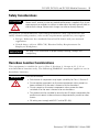
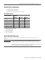
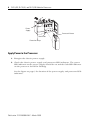
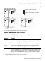
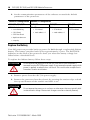
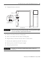
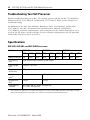
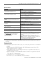
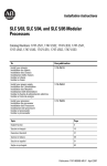
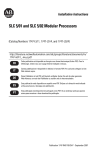
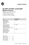
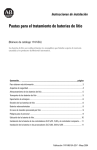
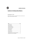
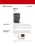
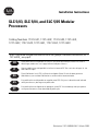
Installation Instructions
SLC 5/03, SLC 5/04, and SLC 5/05 Modular
Processors
Catalog Numbers 1747-L531, 1747-L532, 1747-L533, 1747-L541,
1747-L542, 1747-L543, 1747-L551, 1747-L552, 1747-L553
http://literature.rockwellautomation.com/idc/groups/literature/documents/in/1
747-in009_-mu-p.pdf
FR
Cette publication est disponible en français sous forme électronique (fichier PDF). Pour la
télécharger, rendez-vous sur la page Internet indiquée ci-dessus.
IT
Questa pubblicazione è disponibile in Italiano in formato PDF. Per scaricarla collegarsi al sito
Web indicato sopra.
DE
Diese Publikation ist als PDF auf Deutsch verfügbar. Gehen Sie auf die oben genannte
Web-Adresse, um nach der Publikation zu suchen und sie herunterzuladen.
ES
Esta publicación está disponible en español como PDF. Diríjase a la dirección web indicada
arriba para buscar y descarga esta publicación.
PT
Esta publicação está disponível em portugués como PDF. Vá ao endereço web que aparece
acima para encontrar e fazer download da publicação.
Publication 1747-IN009B-EN-P - March 2008
2
Publication 1747-IN009B-EN-P - March 2008
Installation Instructions
SLC 5/03, SLC 5/04, and SLC 5/05 Modular
Processors
Catalog Numbers 1747-L531, 1747-L532, 1747-L533
1747-L541, 1747-L542, 1747-L543,
1747-L551, 1747-L552, 1747-L553
Topic
Page
Safety Considerations
5
Hazardous Location Considerations
5
Required Tools and Equipment
7
Install the SLC Processor
7
Apply Power to the Processor
8
Loading Your Software
9
Establish Communication to the Processor
9
Replace the Battery
10
Troubleshooting Your SLC Processor
12
Specifications
12
Communication
13
Memory Backup
14
Battery Handling, Storing, and Transporting (Cat. No. 1747-BA)
14
Additional Resources
16
Publication 1747-IN009B-EN-P - March 2008
4
SLC 5/03, SLC 5/04, and SLC 5/05 Modular Processors
Important User Information
Solid state equipment has operational characteristics differing from those of electromechanical equipment.
Safety Guidelines for the Application, Installation and Maintenance of Solid State Controls (publication
SGI-1.1 available from your local Rockwell Automation sales office or online at
http://literature.rockwellautomation.com) describes some important differences between solid state
equipment and hard-wired electromechanical devices. Because of this difference, and also because of the
wide variety of uses for solid state equipment, all persons responsible for applying this equipment must
satisfy themselves that each intended application of this equipment is acceptable.
In no event will Rockwell Automation, Inc. be responsible or liable for indirect or consequential damages
resulting from the use or application of this equipment.
The examples and diagrams in this manual are included solely for illustrative purposes. Because of the many
variables and requirements associated with any particular installation, Rockwell Automation, Inc. cannot
assume responsibility or liability for actual use based on the examples and diagrams.
No patent liability is assumed by Rockwell Automation, Inc. with respect to use of information, circuits,
equipment, or software described in this manual.
Reproduction of the contents of this manual, in whole or in part, without written permission of Rockwell
Automation, Inc., is prohibited.
Throughout this manual, when necessary, we use notes to make you aware of safety considerations.
WARNING
IMPORTANT
ATTENTION
Identifies information about practices or circumstances that can cause an explosion in
a hazardous environment, which may lead to personal injury or death, property
damage, or economic loss.
Identifies information that is critical for successful application and understanding of
the product.
Identifies information about practices or circumstances that can lead to personal injury
or death, property damage, or economic loss. Attentions help you to identify a hazard,
avoid a hazard, and recognize the consequences.
SHOCK HAZARD
Labels may be on or inside the equipment, for example, a drive or motor, to alert
people that dangerous voltage may be present.
BURN HAZARD
Labels may be on or inside the equipment, for example, a drive or motor, to alert
people that surfaces may reach dangerous temperatures.
Publication 1747-IN009B-EN-P - March 2008
SLC 5/03, SLC 5/04, and SLC 5/05 Modular Processors
5
Safety Considerations
ATTENTION
Never install, remove, or wire any module while power is applied. Also, do not
expose processor modules to surfaces or other areas that may typically hold an
electrostatic charge. Electrostatic charges can alter or destroy memory.
For general recommendations concerning installation safety requirements and
safety related work practices, refer to the requirements specific to your region.
• Europe: Reference the standards found in EN 60204 and your national
regulations.
• United States: refer to NFPA 70E, Electrical Safety Requirements for
Employee Workplaces.
IMPORTANT
See page 14 for information on proper battery handling, storage, and
transporting.
Hazardous Location Considerations
This equipment is suitable for use in Class I, Division 2, Groups A, B, C, D or
non-hazardous locations only. The following WARNING statement applies to use in
hazardous locations.
WARNING
EXPLOSION HAZARD
• Substitution of components may impair suitability for Class I, Division 2.
• Do not replace components or disconnect equipment unless power has
been switched off or the area is known to be non-hazardous.
• Do not connect or disconnect components unless power has been
switched off or the area is known to be non-hazardous.
• This product must be installed in an enclosure. All cables connected to the
product must remain in the enclosure or be protected by conduit or other
means.
• All wiring must comply with N.E.C. article 501-4(b).
Publication 1747-IN009B-EN-P - March 2008
6
SLC 5/03, SLC 5/04, and SLC 5/05 Modular Processors
Environnements dangereux
Cet équipement est adapté à une utilisation en environnements de Classe I,
Division 2, Groupes A, B, C, D ou dans des environnements non dangereux. La
mise en garde suivante porte sur une utilisation en environnement dangereux.
AVERTISSEMENT
DANGER D'EXPLOSION
• La substitution de composants peut rendre cet équipement
impropre à une utilisation en environnement de Classe I,
Division 2.
• Ne pas remplacer de composants ou déconnecter l'équipement sans
s'être assuré que l'alimentation est coupée et que l'environnement
est classé non dangereux.
• Ne pas connecter ou déconnecter des composants sans s'être assuré
que l'alimentation est coupée et que l'environnement est classé non
dangereux.
• Ce produit doit être installé dans une armoire. Tous les câbles qui
lui sont connectés doivent rester dans l’armoire ou être protégés
par un conduit ou par d’autres moyens.
• L'ensemble du câblage doit être conforme aux normes d'électricité
en vigueur dans le pays où l'appareil est utilisé.
Publication 1747-IN009B-EN-P - March 2008
SLC 5/03, SLC 5/04, and SLC 5/05 Modular Processors
7
Required Tools and Equipment
• medium blade screwdriver
• programming equipment
• appropriate network interface or cable
Cable Requirements
Network Interface
Processor
SLC 5/03
1747-UIC
(1)
X
SLC 5/04
SLC 5/05
X(4)
X(4)
X
1747-PIC
X
1747-CP3
X
X
1784-PKTX(D)
X(2)
X
1784-PCMK
X(3)
X(5)
10/100Base-T Ethernet
(1)
(2)
(3)
(4)
(5)
X
requires 1747-C13 or 1747-CP3 cable
requires 1784-CP14 cable
requires 1784-PCM4 cable
requires 1747-CP3 cable
requires 1784-PCM6 cable
Install the SLC Processor
Make sure system power is off; then insert the processor into slot 0 of the 1746
chassis.
IMPORTANT
The SLC 500 modular processors must be inserted into the left slot (slot 0).
Inserting the processor in another slot won’t allow the processor to operate.
In addition, remove the protective wrap after installing the processor. Failure to
remove the wrap can cause the power supply to overheat.
Publication 1747-IN009B-EN-P - March 2008
8
SLC 5/03, SLC 5/04, and SLC 5/05 Modular Processors
Power
Supply
Processor Release
Card Guide
Protective Wrap
Apply Power to the Processor
1. Energize the chassis power supply.
2. Check the chassis power supply and processor LED indicators. The power
LED indicator on the power supply should be on and the fault LED indicator
on the processor should be flashing.
See the figure on page 9 for location of the power supply and processor LED
indicators.
Publication 1747-IN009B-EN-P - March 2008
SLC 5/03, SLC 5/04, and SLC 5/05 Modular Processors
9
Power Supply and LED Indicators
Indicates the LED indicator is OFF.
POWER
RUN
FORCE
FLT
DH485
BATT
RS232
Indicates the LED indicator is ON.
Indicates the LED indicator is FLASHING.
Status of LED indicator does not matter.
SLC 5/03
POWER
RUN
FLT
BATT
FORCE
POWER
RUN
FLT
DH+
BATT
RS232
FORCE
ENET
RS232
SLC 5/05
SLC 5/04
Loading Your Software
Refer to your programming software documentation.
Establish Communication to the Processor
1. Refer to the following table to establish communication between the
processor and your personal computer.
Processor
Procedure
SLC 5/03
Connect the 1747-PIC interface from the processor to your personal computer serial port
or connect the 1747-UIC interface from the processor to your personal computer USB
port to the processor using the 1747-C13 or 1747-CP3 cable. You can also use a
1784-PKTX(D) or 1784-PCMK interface, or a 1747-CP3 cable from channel 0 of the
processor to the personal computer serial port.
SLC 5/04
Connect a 1747-CP3 cable from channel 0 of the processor to the personal computer
serial port or connect the 1747-UIC interface from channel 0 of the processor to your
personal computer USB port, or use a 1784-PKTX(D) or 1784-PCMK interface.
SLC 5/05
Connect a 1747-CP3 cable from channel 0 of the processor to the personal computer
serial port, or connect the 1747-UIC interface converter from channel 0 of the processor
to your personal computer USB port. For Ethernet connection, connect channel 1 of the
processor and the PC Ethernet Card to an Ethernet hub using 10/100Base-T compatible
cable.(1)
(1)
EtherNet/IP address must first be set via BOOTP or an RS-232 connection.
Publication 1747-IN009B-EN-P - March 2008
10
SLC 5/03, SLC 5/04, and SLC 5/05 Modular Processors
2. Set the communication parameters of the software to match the default
parameters of the processor.
Channel 0 Configuration Channel 1 Configuration
SLC 5/03, 5/04, 5/05
SLC 5/03
SLC 5/04
SLC 5/05
DF1 Full-duplex:
DH-485:
DH+:
Ethernet:
• no handshaking
• 19.2 Kbaud
• 19.2 Kbaud
• node address = 1
• 57.6 Kbaud
BOOTP enabled
• node address = 1
• CRC Error Check
• duplicate detect on
• no parity
Replace the Battery
Your SLC processor provides back-up power for RAM through a replaceable lithium
battery. This battery provides back-up for approximately 2 years. The BATT LED
indicator on the front of the processor alerts you when the battery voltage has
fallen below a threshold level.
To replace the lithium battery follow these steps.
ATTENTION
Do not remove the processor from the SLC 500 chassis until all power is
removed from the SLC 500 power supply. If you remove the power supply while
power is applied, an electrical arc can occur. This could cause an explosion in
hazardous location installations.
1. Remove power from the SLC 500 power supply.
2. Remove the processor from the chassis by pressing the retainer clips at both
the top and bottom of the module and slide it out.
ATTENTION
Do not expose the processor to surfaces or other areas that may typically hold
an electrostatic charge. Electrostatic charges can alter or destroy memory.
Publication 1747-IN009B-EN-P - March 2008
SLC 5/03, SLC 5/04, and SLC 5/05 Modular Processors
11
3. Unplug the battery connector.
Battery
Red
White
Battery Connector
Left Side View
IMPORTANT
The SLC 5/03, 5/04, and 5/05 processors have a capacitor that provides at least
30 minutes of battery back-up while the battery is disconnected. Data in RAM
is not lost if the battery is replaced within 30 minutes.
4. Remove the battery from the retaining clips.
5. Insert a new battery into the battery retaining clips.
6. Plug the battery connector into the socket as shown above.
7. Re-insert the module into the SLC 500 chassis.
8. Restore power to the SLC 500 power supply.
9. Close the processor door.
IMPORTANT
See page 14 for information on proper battery handling, storage, and
transporting.
Publication 1747-IN009B-EN-P - March 2008
12
SLC 5/03, SLC 5/04, and SLC 5/05 Modular Processors
Troubleshooting Your SLC Processor
Before troubleshooting your SLC 500 system, please obtain an SLC 500 Modular
Hardware Style User Manual, publication 1747-UM011. Refer to the chapter on
troubleshooting.
In addition to the SLC 500 Modular Hardware Style User Manual, publication
1747-UM011, the SLC 500 Instruction Set Reference Manual, publication
1747-RM001, contains explanations and examples for the entire instruction set as
well as for all status words and bits. It also contains explanations for all possible
fault codes found in status word S:6.
Specifications
SLC 5/03, SLC 5/04, and SLC 5/05 Processors
Attribute
SLC 5/03
L531
Memory (words) 8 K
SLC 5/04
L532
L533
L541
L542
L543
L551
L552
L553
16 K
32 K
16 K
32 K
64 K
16 K
32 K
64 K
I/O capacity,
max
4096 discrete inputs/4096 discrete outputs
Local system,
max
3 chassis / 30 slots
Programming
instructions
107
Typical scan
time(1)
1 ms/K
0.9 ms/K
Bit execution
(XIC)
0.44 µs
0.37 µs
Programming
software
SLC 5/03s and SLC 5/04s: RSLogix 500,
SLC 5/05s: RSLogix 500
(1)
SLC 5/05
The scan times are typical for a 1 K ladder logic program consisting of simple ladder logic and communication servicing.
Actual scan times depend on your program size, instructions used, and the communication protocol.
Publication 1747-IN009B-EN-P - March 2008
SLC 5/03, SLC 5/04, and SLC 5/05 Modular Processors
13
Specifications
Attribute
Value
Power supply loading at 5V dc
500 mA for the SLC 5/03 processor
1.0 A for the SLC 5/04 and 5/05 processors
Power supply loading at 24V dc
175 mA for the SLC 5/03 processor
0 mA for the SLC 5/04 processor (1)
0 mA for the SLC 5/05 processor
Program scan hold-up time after loss of
power
20 ms...3 s (dependent on power supply loading)
Noise immunity
NEMA Standard ICS 2-230
Vibration
Displacement: 0.015 in., peak-to-peak at 5-57 Hz
Acceleration: 2.5 g at 57...2000 Hz
Shock, operating
30 g
Ambient temperature rating, operating
0...60 °C (32...140 °F)
Ambient temperature rating, storage
-40...85 °C (-40...185 °F)
Humidity
5 to 95% without condensation
Agency certification
See http://ab.com for declarations of
conformity, certificates, and other
certification details.
UL Listed Industrial Control Equipment
C-UL Listed Industrial Control Equipment for use in
Canada
UL Listed Industrial Control Equipment for use in
Class I, Division 2, Hazardous Locations Groups A, B,
C or D
CE compliant for all applicable directives
C-Tick marked for all applicable acts
(1)
SLC 5/04 Processors manufactured prior to April 2002 draw 200 mA at 24V dc. Check your label to verify your processor’s
current draw.
Communication
Communication options for the SLC 5/03, 5/04, and 5/05 processors are as follows:
• DH485
• RS-232 protocols (DF1 Full-duplex, DF1 Half-duplex master/slave, DF1
Radio Modem, DH-485, or ASCII)
• Data Highway Plus (A ControlLogix Gateway is required for the SLC 5/03
and SLC 5/05 processors.)
• Ethernet TCP/IP (A 1761-NET-ENI interface module is required for the SLC
5/03 and SLC 5/04 processors)
• ControlNet (via a 1747-KFC15 module)
• DeviceNet (via a 1761-NET-DNI interface module)
Publication 1747-IN009B-EN-P - March 2008
14
SLC 5/03, SLC 5/04, and SLC 5/05 Modular Processors
Memory Backup
The following table shows the memory backup options for the SLC 5/03, 5/04, and
5/05 processors. Flash EPROMs (Flash Erasable Programmable Read Only Memory)
combine the versatility of EEPROMs (Electrically-Erasable Programmable Read Only
Memory) with the security of UVPROMs (UV-Erasable PROM).
Memory
Backup Option
SLC 5/03 Processor
(1747-L531, 1747-L532,
1747-L533)
SLC 5/04 Processor
(1747-L541, 1747-542,
1747-543)
SLC 5/05 Processor
(1747-L551, 1747-552,
1747-553)
Flash EPROM
1747-M13
(OS302 Series C or later)
1747-M13
(OS401 Series C or later)
1747-M13
(OS501 Series C or later)
Battery Handling, Storing, and Transporting (Cat. No. 1747-BA)
Handling
ATTENTION
Do not charge the batteries. An explosion could result or the cells could
overheat causing burns. Do not open, puncture, crush, or otherwise mutilate
the batteries. An explosion may result and/or toxic, corrosive, and flammable
liquids would be exposed.
Storing
Store the lithium batteries in a cool, dry environment, typically 20...25 °C
(68...77 °F) and 40% to 60% relative humidity.
Transporting
One or Two Batteries - Up to two batteries can be shipped together within the
United States without restriction. Regulations governing shipment to or within other
countries may differ.
Three or More Batteries - Procedures for the transportation of three or more
batteries shipped together within the United States are specified by the Department
of Transportation (DOT) in the Code of Federal Regulations, CFR49,
“Transportation.”
An exemption to these regulations, DOT - E7052, covers the transport of certain
hazardous materials classified as flammable solids. This exemption authorizes
transport of lithium batteries by motor vehicle, rail freight, cargo vessel, and
cargo-only aircraft, providing certain conditions are met. Transport by passenger
aircraft is not permitted.
Publication 1747-IN009B-EN-P - March 2008
SLC 5/03, SLC 5/04, and SLC 5/05 Modular Processors
15
Shipment of depleted batteries for disposal may be subject to specific regulation of
the countries involved or to regulations endorsed by those countries, such as the
IATA Restricted Articles Regulations of the International Air Transport Association,
Geneva, Switzerland.
IMPORTANT
Regulations for transportation of lithium batteries are periodically revised.
Refer to http://www.dot.gov for the latest shipping information.
ATTENTION
Do not incinerate or dispose of lithium batteries in general trash collection.
Explosion or violent rupture is possible. Batteries should be collected for
disposal in a manner to prevent against short circuiting, compacting, or
destruction of case integrity and hermetic seal.
For disposal, batteries must be packaged and shipped in accordance with
transportation regulations, to a proper disposal site. The U.S. Department of
Transportation authorizes shipment of “Lithium batteries for disposal” by motor
vehicle only in regulation 173.1015 of CFR 49 (effective January 5, 1983). For
additional information contact:
U.S. Department of Transportation
Research and Special Programs Administration
400 Seventh Street, S.W.
Washington, D.C. 20590
Although the Environmental Protection Agency at this time has no regulations
specific to lithium batteries, the material contained may be considered toxic,
reactive, or corrosive. The person disposing of the material is responsible for any
hazard created in doing so. State and local regulations may exist regarding the
disposal of these materials.
For a lithium battery material safety data sheet, contact the manufacturer.
Sanyo Energy Corporation
Tadarand U.S. Battery Division
or
600 Supreme Drive
2 Seaview Blvd.
Bensenville, IL 60106
Port Washington, NY 11050
USA
USA
Publication 1747-IN009B-EN-P - March 2008
16
Additional Resources
Resource
Description
SLC 500 Modular Hardware Style User
Manual, publication 1747-UM011
A more detailed description on how to install and use
your modular SLC 500 system.
SLC 500 Instruction Set Reference
Manual, publication 1747-RM001
A reference manual that contains status file data,
instruction set, and troubleshooting information.
You can view or download publications at
http://literature.rockwellautomation.com. To order paper copies of technical
documentation, contact your local Rockwell Automation distributor or sales
representative.
Publication 1747-IN009B-EN-P - March 2008
17
Notes:
Publication 1747-IN009B-EN-P - March 2008
18
Notes:
Publication 1747-IN009B-EN-P - March 2008
19
Notes:
Publication 1747-IN009B-EN-P - March 2008
Rockwell Automation Support
Rockwell Automation provides technical information on the Web to assist you in
using its products. At http://support.rockwellautomation.com, you can find
technical manuals, a knowledge base of FAQs, technical and application notes,
sample code and links to software service packs, and a MySupport feature that you
can customize to make the best use of these tools.
For an additional level of technical phone support for installation, configuration,
and troubleshooting, we offer TechConnect Support programs. For more
information, contact your local distributor or Rockwell Automation representative,
or visit http://support.rockwellautomation.com.
Installation Assistance
If you experience a problem with a hardware module within the first 24 hours of
installation, please review the information that's contained in this manual. You can
also contact a special Customer Support number for initial help in getting your
module up and running.
United States
1.440.646.3434
Monday – Friday, 8am – 5pm EST
Outside United
States
Please contact your local Rockwell Automation representative for any
technical support issues.
New Product Satisfaction Return
Rockwell tests all of its products to ensure that they are fully operational when
shipped from the manufacturing facility. However, if your product is not
functioning, it may need to be returned.
United States
Contact your distributor. You must provide a Customer Support case number
(see phone number above to obtain one) to your distributor in order to
complete the return process.
Outside United
States
Please contact your local Rockwell Automation representative for return
procedure.
Allen-Bradley, Rockwell Automation, TechConnect, SLC, SLC 5/03, Data Highway Plus, DH+, RSLogix 500, and SLC 500 are
trademarks of Rockwell Automation, Inc.
Trademarks not belonging to Rockwell Automation are the property of their respective companies.
Publication 1747-IN009B-EN-P - March 2008
Supersedes Publication 1747-IN009A-EN-P - April 2007
PN 40072-090-01(6)
Copyright © 2008 Rockwell Automation, Inc. All rights reserved. Printed in Singapore.