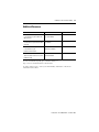
1
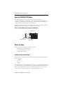
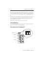
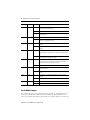
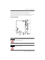
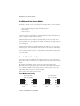
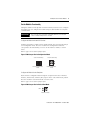
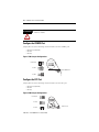
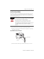
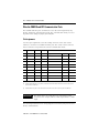
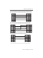
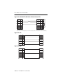
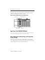
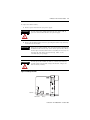
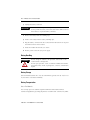
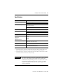
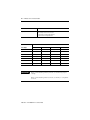
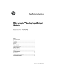
Installation Instructions
DH485/RS-232C Interface Module
Catalog Number 1747-KE
Inside . . .
For
See Page
Important User Information
2
Hazardous Location Considerations
3
Environnements dangereux
3
About the DH485/RS-232C Module
4
Before You Begin
4
Configure the CONFIG Port
10
Configure the DF1 Port
10
Install the Interface Module
11
Wire the CONFIG and DF1 Communication
Ports
12
Wire to the DH485 Port
15
Apply Power to Your DH485/RS-232C Module
16
Battery Replacement, Handling, Storage, and
Transportation (Cat. No. 1747-BA)
16
Specifications
21
Additional Resources
23
Publication 1747-IN006B-EN-P - October 2005
2
DH485/RS-232C Interface Module
Important User Information
Solid state equipment has operational characteristics differing from those of electromechanical equipment.
Safety Guidelines for the Application, Installation and Maintenance of Solid State Controls (Publication
SGI-1.1 available from your local Rockwell Automation sales office or online at
http://www.literature.rockwellautomation.com) describes some important differences between solid state
equipment and hard-wired electromechanical devices. Because of this difference, and also because of the
wide variety of uses for solid state equipment, all persons responsible for applying this equipment must
satisfy themselves that each intended application of this equipment is acceptable.
In no event will Rockwell Automation, Inc. be responsible or liable for indirect or consequential damages
resulting from the use or application of this equipment.
The examples and diagrams in this manual are included solely for illustrative purposes. Because of the many
variables and requirements associated with any particular installation, Rockwell Automation, Inc. cannot
assume responsibility or liability for actual use based on the examples and diagrams.
No patent liability is assumed by Rockwell Automation, Inc. with respect to use of information, circuits,
equipment, or software described in this manual.
Reproduction of the contents of this manual, in whole or in part, without written permission of Rockwell
Automation, Inc., is prohibited.
Throughout this manual, when necessary, we use notes to make you aware of safety considerations.
WARNING
IMPORTANT
ATTENTION
Identifies information about practices or circumstances that can cause an explosion in
a hazardous environment, which may lead to personal injury or death, property
damage, or economic loss.
Identifies information that is critical for successful application and understanding of
the product.
Identifies information about practices or circumstances that can lead to personal injury
or death, property damage, or economic loss. Attentions help you identify a hazard,
avoid a hazard and recognize the consequences.
SHOCK HAZARD
Labels may be located on or inside the equipment (for example, drive or motor) to alert
people that dangerous voltage may be present.
BURN HAZARD
Labels may be located on or inside the equipment (for example, drive or motor) to alert
people that surfaces may be dangerous temperatures.
Publication 1747-IN006B-EN-P - October 2005
DH485/RS-232C Interface Module
3
Hazardous Location Considerations
This equipment is suitable for use in Class I, Division 2, Groups A, B, C, D or
non-hazardous locations only. The following WARNING statement applies to use in
hazardous locations.
ATTENTION
WARNING: EXPLOSION HAZARD
Substitution of components may impair suitability for Class I,
Division 2.
Do not replace components or disconnect equipment unless
power has been switched off.
Do not connect or disconnect components unless power has been
switched off.
All wiring must comply with N.E.C. article 501, 502, 503, and/or
C.E.C. section 18-1J2 as appropriate.
Environnements dangereux
Cet équipement est conçu pour être utilisé dans des environnements de Classe I,
Division 2, Groupes A, B, C, D ou non dangereux. La mise en garde suivante
s’applique à une utilisation dans des environnements dangereux.
ATTENTION
AVERTISSEMENT: DANGER D’EXPLOSION
La substitution de composants peut rendre cet équipement
impropre à une utilisation en environnement de Classe 1, Division
2.
Ne pas remplacer de composants ou déconnecter l'équipement
sans s'être assuré que l'alimentation est coupée.
Ne pas connecter ou déconnecter des composants sans s'être
assuré que l'alimentation est coupée.
Publication 1747-IN006B-EN-P - October 2005
4
DH485/RS-232C Interface Module
About the DH485/RS-232C Module
The DH485/RS-232C interface module, catalog number 1747-KE, is a
communication interface module that acts as a bridge between DH485 networks
and devices requiring DF1 protocol. The DF1 port on the interface module can be
configured for RS-232/423, RS-422, or RS-485 devices.
Residing in an SLC 500 chassis, the module is ideally used as an interface module,
linking remote DH485 networks via a modem to a central host.
Figure 1 Interface Module Placement on SLC 500 Chassis
SLC 500 Controller
1747-AIC Link Coupler
1747-C11 Cable
Before You Begin
Before you begin to install the module, you need to:
• identify the communication ports,
• locate the LED indicators, and
• set the module jumpers.
Identify the Communication Ports
There are three communication ports on the front of the DH485/RS-232C interface
module. They are:
• CONFIG
• DF1
• DH485
The CONFIG port is used to configure the module with an ASCII terminal. This port
is a serial port that accommodates RS-232/423, RS-422, and RS-485 communication
modes. The CONFIG port is capable of operating full-duplex at 300, 600, 1200,
2400, 4800, 9600, and 19200 Kbps. It is electrically isolated to 500V dc.
Publication 1747-IN006B-EN-P - October 2005
DH485/RS-232C Interface Module
5
The DF1 port is used to interface the module with user devices or a modem using
DF1 protocol. This port is a serial port that accommodates RS-232/423, RS-422, and
RS-485 communication modes. The DF1 port is capable of operating full-duplex at
300, 600, 1200, 2400, 4800, 9600, and 19200 Kbps. It is electrically isolated to 500V
dc.
The DH485 port is used to interface the module with the DH485 network. This port
is not isolated and cannot directly drive a multi-node DH485 network. You must
use a 1747-AIC link coupler to link port DH485 with the DH485 network that
includes multiple SLC 500 controllers.
Refer to Figure 2 for the location of the communication ports.
Locate the LED Indicators
There are eight LED indicators on the front of the module. These LED indicators are
used for module diagnostics and status indication.
Refer to Figure 2 for the location of the LED indicators.
Figure 2 Communication Ports and LED Indicators
DH485/RS-232C
LED Indicators
DH-485/RS-232C
ACT
FAULT
485
CFG
BA LOW
H/D
DF1
F/D
INTERFACE
CONFIG Port
5
4
3
2
1
DF1 Port
DH485 Port
9
8
7
6
CONFIG
5
4
3
2
1
9
8
7
6
DF1
DH485
Publication 1747-IN006B-EN-P - October 2005
6
DH485/RS-232C Interface Module
LED
Color
Status
Indication
ACT
Green
ON(1)
The module is receiving power from the backplane, is configured
correctly, and is in the Run mode.
Flashing
The module requires configuration or is being configured.
OFF
The module is not receiving power from the backplane. A fault
condition exists.
ON
Port DH485 on the module is active for communication.
OFF
Port DH485 on the module is not active for communication or the
module is in Configuration mode.
Flashing
The CONFIG port on the module is transmitting or receiving
signals.
OFF
The CONFIG port on the module is not transmitting or receiving
signals.
Flashing
The DF1 port on the module is transmitting or receiving signals.
The flashing may occur rapidly so the LED indicator appears to be
on.
OFF
The DF1 port on the module is not transmitting or receiving signals
or the module is in Configuration mode.
ON
A system problem was detected during background diagnostics.
Cycle power to reset. Contact your local Rockwell Automation
representative if the LED indicator remains on.
OFF
No system problems are detected during background diagnostics.
ON
The voltage of the battery that backs up RAM is low. A new
battery is needed.
OFF
The voltage of the battery that backs up RAM is at an acceptable
level.
ON
The module is configured for half-duplex DF1 protocol (local or
remote).
OFF
The module is not configured for half-duplex DF1 protocol.
ON
The module is configured for full-duplex DF1 protocol.
OFF
The module is not configured for full-duplex DF1 protocol.
485
CFG
DF1
Green
Green
Green
FAULT
Red
BA LOW
Red
H/D
F/D
(1)
Amber
Amber
Indicates normal operation after the module has been configured.
Set the Module Jumpers
The module have three sets of jumpers that you need to set. Jumper JW1 lets you
select the communication interface for the CONFIG port. Jumper JW2 lets you
select the communication interface for the DF1 port. Jumper JW4 lets you select the
Publication 1747-IN006B-EN-P - October 2005
DH485/RS-232C Interface Module
7
functionality and mode of the interface module. The horizontal or vertical
orientation of the jumper determines the module’s functionality.
The position of the jumper determines the module’s mode (Configuration or Run),
and thus, which method is used to configure the module (ASCII terminal or
backplane communications).
Figure 3 Jumper Locations
JW1
CAT
FRN
SLC 500
INTERACE MODULE
SER
SERIAL NO.
54 3 2 1
CONFIG
9 87 6
54 3 2 1
DF1
9 87 6
JW4
DH485
Battery
JW2
ATTENTION
Do not expose the module to surfaces or other areas that may
typically hold an electrostatic charge. Electrostatic charges can
alter or destroy memory.
ATTENTION
Settings other than those shown for each jumper may cause
damage to the module.
Publication 1747-IN006B-EN-P - October 2005
8
DH485/RS-232C Interface Module
Use a Modem with Your Interface Module
The interface module can be connected to the following direct connect modems.
•
•
•
•
Manual
Data Terminal Equipment (DTE) Controlled Answer
Auto Answer
Direct Connect
The manual modem is usually an acoustically-coupled modem. A person on each
end of the phone line establishes the connection. The handset is inserted into an
acoustic coupler to complete the connection.
A DTE Controlled Answer modem is attached directly to the phone lines. The
interface module acts as the DTE, which controls the modem via the DTR, DSR, and
DCD signals. The module incorporates time-outs and tests to properly operate these
types of modems.
An Auto Answer modem has self-contained time outs and tests. They can answer
and hang up the phone automatically. The module has no means of controlling an
auto-dial modem, but it can be used in conjunction with a separate auto–dialer.
A Direct Connect modem connects to a dedicated, leased phone line and remains
active at all times.
Choose the Module’s Functionality
Your series B interface module has the ability to function as a series A interface
module. This feature is useful if you are replacing a series A module with a series B
module.
The module’s functionality depends on the placement of the JW4 jumper.
Horizontal placement of the jumper gives the module functionality equivalent to a
series A interface module, while vertical placement of the jumper accesses the
added functionality of a series B interface module.
Refer to page 7 for location of jumper JW4.
Figure 4 Module Functionality
Series A Functionality
(mod. config. ID=4209)
Horizontal Configuration
Mode
Horizontal Run
Mode
Publication 1747-IN006B-EN-P - October 2005
Series B Functionality
(mod. config. ID=3509)
Vertical Configuration
Mode
Vertical Run
Mode
DH485/RS-232C Interface Module
9
Set the Module’s Functionality
Setting the module’s mode depends on which method you want to use to configure
the module. You can configure the module using an ASCII terminal or backplane
communication.
IMPORTANT
You can only use backplane communications if you selected
series B functionality for the module.
Configure the Module with an ASCII Terminal
Configure the interface module with an ASCII terminal only when the JW4 jumper
is in Configuration mode. Place the module in the Configuration mode that
corresponds to the functionality you chose for the interface module, as shown
below.
Refer to page 7 for location of jumper JW4.
Figure 5 JW4 Jumper Set for Configuration Mode
Series A Functionality
Horizontal Configuration
Mode
Series B Functionality
Vertical Configuration
Mode
Configure the Module via the Backplane
Read and write configuration data through the backplane with series B interface
modules, and then only when the JW4 jumper is in the vertical Run mode position.
Place the module in vertical Run mode as shown below.
Refer to page 7 for location of jumper JW4.
Figure 6 JW4 Jumper Set for Vertical Run Mode
JW4
Vertical Run Mode
Publication 1747-IN006B-EN-P - October 2005
10
DH485/RS-232C Interface Module
ATTENTION
Other jumper settings are invalid and may cause damage to the
interface module.
Configure the CONFIG Port
Jumper JW1 selects the following electrical interface for the CONFIG port.
• RS-232/423 (default)
• RS-422
• RS-485
Figure 7 JW1 Jumper Configurations
RS-423/232
2 4 6 8 10
1 3 5 7 9
RS-422
JW1 CONFIG Port
RS-485
Configure the DF1 Port
Jumper JW2 selects the following electrical interface for the DF1 port.
• RS-232/423 (default)
• RS-422
• RS-485
Figure 8 JW2 Jumper Configurations
RS-423/232
9 7 5 3 1
RS-485
10 8 6 4 2
JW2 DF1 Port
RS-422
Publication 1747-IN006B-EN-P - October 2005
DH485/RS-232C Interface Module
11
Install the Interface Module
Your interface module may be installed in any open slot of an SLC 500 1746 I/O
chassis except the first slot of the first chassis. The first slot is reserved for the
controller or adapter module. The interface module can also be installed in an SLC
fixed controller expansion chassis.
ATTENTION
Never install, remove, or wire any module while power is applied.
Also, do not expose the modules to surfaces or other areas that
may typically hold an electrostatic discharge.
Electrostatic discharge can damage integrated circuits or
semiconductors if you touch backplane connector pins.
If the equipment is not installed and used as described in the SLC
500 Modular Hardware Style User Manual, publication
1747-UM011, the protection provided by the equipment may be
impaired.
1. Turn off power to the chassis where you will insert the module.
2. Align the circuit board of the module with the card guide of a slot (except
slot 0) in the 1746 chassis.
Figure 9 Module Location in the Chassis
Module Release
Card Guide
3. Slide the module in until the top and bottom retainer clips are secured.
Publication 1747-IN006B-EN-P - October 2005
12
DH485/RS-232C Interface Module
Wire the CONFIG and DF1 Communication Ports
The CONFIG and DF1 ports communicate to user devices through RS-232/423,
RS-422, and RS-485 communication modes. The communication mode you select
depends on the setting of jumpers JW1 and JW2.
Pin Assignments
Use these pin assignments to wire the mating connector of the cable used to
interface a user device to CONFIG and DF1 ports. The sockets of this connector
must be wired to correspond to the selected communication mode.
Pin
RS-232/423
RS-422
RS-485
IBM AT Standard RS-232/423
Signal
25-pin
9-pin
1
(1)
TXD -
TRXD -
DCD or CD
8
1
2
RXD
RXD -
(3)
RXD
3
2
3
TXD
(2)
(2)
TXD
2
3
4
DTR
(2)
(2)
DTR
20
4
5
COMMON
COMMON
COMMON
COMMON
7
5
6
DSR
RXD +
(3)
DSR
6
6
7
RTS
(2)
(2)
RTS
4
7
8
CTS
(2)
(2)
CTS
5
8
9
(1)
TXD +
TRXD +
RI
22
9
(1)
In RS-423 mode, these pins are still connected to their RS-422 loads. Do not use these pins in RS-423 mode.
(2)
In RS-422 and RS-485 modes, these pins are connected to their RS-423 drivers and receivers. Do not use these pins in
either RS-422 or RS-485 mode.
(3)
In RS-485 mode, these pins are still connected to their RS-422 receivers. Do not use these pins in RS-485 mode.
IMPORTANT
The signal names on a DCE device are viewed from a DTE
perspective. For example, TXD is a DTE output and also a DCE
input.
The following illustrations show wiring diagrams for the RS-232/423, RS-422, and
RS-485 communications.
Publication 1747-IN006B-EN-P - October 2005
DH485/RS-232C Interface Module
13
Figure 10 RS-232/423 DTE to DCE (Non-modem Hardware Handshake to DCE)
NC
1
CD
1
8
RXD
2
3
4
RXD
2
3
4
3
2
20
5
6
7
6
7
8
9
4
5
22
TXD
DTR
TXD
DTR
5
6
COM
DSR
COM
DSR
7
8
9
RTS
CTS
NC
RTS
CTS
RI
Figure 11 RS-232/423 DTE to DCE (Modem Hardware Handshake to DCE)
NC
1
CD
1
8
RXD
2
3
4
RXD
2
3
4
3
2
20
5
6
7
6
7
8
9
4
5
22
TXD
DTR
COM
DSR
RTS
CTS
NC
TXD
DTR
5
6
COM
DSR
7
8
9
RTS
CTS
RI
Figure 12 RS-232/423 DTE to DCE (No Handshake to DCE)
NC
1
CD
1
8
RXD
RXD
COM
2
3
4
5
COM
2
3
4
5
3
2
20
7
DSR
6
DSR
6
6
RTS
7
8
9
RTS
7
8
9
4
5
22
TXD
DTR
CTS
NC
TXD
DTR
CTS
RI
(1)
(1)
(1) Connect DSR to DTR and CTS to RTS when using devices that cannot disable their hardware handshaking.
Publication 1747-IN006B-EN-P - October 2005
14
DH485/RS-232C Interface Module
Figure 13 RS-232/423 DTE to DCE (Soft or No Handshake to DCE)
NC
1
CD
1
8
RXD
2
RXD
2
3
TXD
3
4
TXD
DTR
DTR
3
4
2
20
COM
5
COM
5
7
DSR
6
DSR
6
6
RTS
7
8
9
RTS
7
8
9
4
5
22
CTS
NC
CTS
RI
(1)
(1)
(1) Connect DSR to DTR and CD, and CTS to RTS when using devices that cannot disable their hardware handshaking.
Figure 14 RS-422
TXD-
1
RXD-
RXD-
2
TXD-
3
4
COM
5
COM
RXD+
6
TXD+
TXD+
7
8
9
RXD+
1
TRXD-
Figure 15 RS-485
TRXD-
2
3
4
COM
5
COM
6
TRXD+
7
8
9
Publication 1747-IN006B-EN-P - October 2005
TRXD+
DH485/RS-232C Interface Module
15
Wire to the DH485 Port
The DH485 port can communicate to user devices through the DH485
Communication mode. Use a 1747-C10, 1747-C11, or 1747-C13 interface cable to
connect the module to a link coupler interfaced with the DH485 network.
If you use the 1747-C10 or 1747-C11 cable, it connects between the DH485 port on
the interface module and the J1 (CPU) connector on the link coupler. Power for the
link coupler comes from the interface module.
Figure 16 Wire to the DH485 Port via 1747-C10 and 1747-C11 Cable
Link Coupler
(1747-AIC)
Interface Module
(1747-KE)
CONFIG Port
DF1 Port
J1 (CPU)
DH485 Port
Cable (1747-C11)
(comms or power)
If you use the 1747-C13 cable, connect it between the DH485 port on the interface
module and the J2 (Peripheral) connector on the link coupler. Power for the link
coupler must be provided from the SLC 500 module DH485 port or external power
source.
Figure 17 Wire to the DH485 Port via 1747-C13 Cable
Link Coupler
(1747-AIC)
Interface Module
(1747-KE)
CONFIG Port
J1 (Peripheral)
DF1 Port
J1 (CPU)
Cable (1747-C11)
DH485 Port
Cable (1747-C13)
Publication 1747-IN006B-EN-P - October 2005
16
DH485/RS-232C Interface Module
The 1747-C13 cable can also connect the interface module’s DH485 port directly to
a single SLC controller or fixed controller. It connects the DH485 port on the
module to the DH485 port on the SLC 500 controller.
Figure 18 Interface Module Connected to SLC 500 Controller
SLC Controller
Interface Module (1747-KE)
Cable (1747-C13)
DH485 Port
Apply Power to Your DH485/RS-232C Module
Once you have installed your DH485/RS-232C interface module in your SLC 500
system, you are already to apply power to your SLC 500 system.
Battery Replacement, Handling, Storage, and Transportation
(Cat. No. 1747-BA)
Your module provides back-up power for RAM through a replaceable lithium
battery (cat. no. 1747-BA). This battery provides back-up for approximately five
years. A BAT LOW indicator on the front of the module alerts you when the battery
voltage has fallen below the replace battery threshold level.
Publication 1747-IN006B-EN-P - October 2005
DH485/RS-232C Interface Module
17
To replace the lithium battery:
1. Remove power from the SLC 500 power supply.
ATTENTION
Do not remove the module from the SLC 500 chassis until all
power is removed from the SLC 500 power supply.
2. Remove the module from the chassis by pressing the retainer clips at the top
and bottom of the module.
IMPORTANT
If the top or bottom retainer clips are broken while removing the
module from the chassis, they can be easily replaced. Pry off any
broken clips from the bottom with a screwdriver, if necessary. Do
not twist off. Snap in the replacement clip. Order cat. no.
1746-R15 (two per package).
ATTENTION
Do not expose the module to surfaces or other areas that may
typically hold an electrostatic charge. Electrostatic charges can
alter or destroy memory.
Figure 19 Battery Location
CAT
FRN
SLC 500
INTERACE MODULE
SER
SERIAL NO.
54 3 2 1
CONFIG
9 87 6
54 3 2 1
DF1
9 87 6
DH485
Red Wire
White Wire
Battery
Publication 1747-IN006B-EN-P - October 2005
18
DH485/RS-232C Interface Module
3. Unplug the battery connector.
IMPORTANT
The module has a capacitor that provides 30 minutes of battery
back-up while the battery is disconnected. Data in RAM is not lost
if the battery is replaced within 30 minutes.
4. Remove the battery from the retaining clips.
5. Insert a new battery into the battery retaining clips.
6. Plug the battery connector into the socket with the red lead wire on top and
the white lead wire on the bottom.
7. Insert the module into the SLC 500 chassis.
8. Restore power to the SLC 500 power supply.
Battery Handling
ATTENTION
Do not charge the batteries. An explosion could result or cells
could overheat causing burns.
Do not open, puncture, crush, or otherwise mutilate the batteries.
An explosion may result, exposing toxic, corrosive, or flammable
liquids.
Battery Storage
Store the lithium batteries in a cool, dry environment, typically 20 to 25 °C (68 to 77
°F) and 40% to 60% relative humidity.
Battery Transportation
One or Two Batteries
You can ship up to two batteries together within the United States without
restriction. Regulations governing shipment to or within other countries may differ.
Publication 1747-IN006B-EN-P - October 2005
DH485/RS-232C Interface Module
19
Three or More Batteries
Procedures for the transportation of three or more batteries shipped together within
the United States are specified by the Department of Transportation (DOT) in the
Code of Federal Regulations, CFR49, “Transportation.” An exemption to these
regulations, DOT - E7052, covers the transport of certain hazardous materials
classified as flammable solids. This exemption authorizes transport of lithium
batteries by motor vehicle, rail freight, cargo vessel, and cargo-only aircraft,
providing certain conditions are met. Transport by passenger aircraft is not
permitted.
Shipment of depleted batteries for disposal may be subject to specific regulation of
the countries involved or to regulations endorsed by those countries, such as the
IATA Restricted Articles Regulations of the International Air Transport Association,
Geneva, Switzerland.
IMPORTANT
Regulations for transportation of lithium batteries are periodically
revised.
ATTENTION
Do not incinerate or dispose of lithium batteries in general trash
collection. Explosion or violent rupture is possible. Batteries
should be collected for disposal in a manner to prevent against
short circuiting, compacting, or destruction of case integrity and
hermetic seal.
For disposal, batteries must be packaged and shipped in accordance with
transportation regulations, to a proper disposal site. The U.S. Department of
Transportation authorizes shipment of “Lithium batteries for disposal” by motor
vehicle only in regulation 173.1015 of CFR 49 (effective January 5, 1983). For
additional information contact:
U.S. Department of Transportation
Research and Special Programs Administration
400 Seventh Street, S.W.
Washington, D.C. 20590
Although the Environmental Protection Agency at this time has no regulations
specific to lithium batteries, the material contained may be considered toxic,
reactive, or corrosive. The person disposing of the material is responsible for any
hazard created in doing so. State and local regulations may exist regarding the
disposal of these materials.
Publication 1747-IN006B-EN-P - October 2005
20
DH485/RS-232C Interface Module
For a lithium battery material safety data sheet, contact the manufacturer.
Sanyo Energy Corporation
600 Supreme Drive
Tadarand Electronics
or
2 Seaview Blvd.
Bensenville, IL 60106
Port Washington, NY 11050
USA
USA
Publication 1747-IN006B-EN-P - October 2005
DH485/RS-232C Interface Module
21
Specifications
Specification
Value
Power Supply Loading at 5V dc
0.150 A (module only)
0.150 A (module with link coupler)
Power Supply Loading at 24V dc
0.070 A (module only)(2)(3)
0.125 A (module with link coupler)
Noise Immunity
NEMA Standard ICS 2-230
Vibration
Displacement: 0.015 in., peak-to-peak at 5...57 Hz
Acceleration: 2.5 g at 57...2000 Hz
Shock (operating)
30 g
Port Isolation(1)
CONFIG Port
DF1 Port
CONFIG and DF1 Port
500V ac
500V ac
500V ac
Ambient Temperature Rating
Operating: 0...+60 °C (+32...+140 °F)
Storage: -40...+85 °C (-40...+185 °F)
Humidity
5...95% without condensation
Clock/Calendar Accuracy
±1 minute/month at 25 °C (77 °F)
+0, -6 minute/month at 60 °C (140 °F)
(1)
Port DH485 is not isolated.
(2)
If a 1747-AIC link coupler is connected to the 1747-KE module with a 1747-C11 cable, the link coupler draws its power
power (0.085 A @24V dc) through the module. Add this to the current listed for the link coupler requirements.
(3)
If a 1747-AIC link coupler is connected to the 1747-KE module with a 1747-C13 cable, then the power for the link coupler
comes from either an SLC 500 controller or an external power supply.
IMPORTANT
The interface module receives its power from the SLC backplane.
The power consumption of the module must be taken into
consideration when planning your SLC 500 system. Refer to the
documentation supplied with your SLC 500 fixed or modular
controller for additional information on power supplies and
current requirements.
Publication 1747-IN006B-EN-P - October 2005
22
DH485/RS-232C Interface Module
Certification
Value
Agency Certification
c-UL-us listed
Class I, Groups A, B, C or D, Division 2
CE compliant for all applicable directives
C-Tick marked for all applicable acts
Communication
Max. Distance Allowed in Meters (Feet)
Rate (Kbps)
RS-232
RS-423
RS-422
RS-485
300
15 (50)
1230 (4000)
1230 (4000)
1230 (4000)
600
15 (50)
920 (3000)
1230 (4000)
1230 (4000)
1200
15 (50)
770 (2500)
1230 (4000)
1230 (4000)
2400
15 (50)
502 (1650)
1230 (4000)
1230 (4000)
4800
15 (50)
245 (800)
1230 (4000)
1230 (4000)
9600
15 (50)
120 (400)
1230 (4000)
1230 (4000)
19200
15 (50)
60 (200)
1230 (4000)
1230 (4000)
IMPORTANT
When communicating in RS-232 mode, use the RS-423 jumper
settings.
When communicating in RS-423 mode, use RS-423 or compatible
receivers.
Publication 1747-IN006B-EN-P - October 2005
DH485/RS-232C Interface Module
23
Additional Resources
For
Refer to this document
Pub. No.
A more detailed description on how
to install and use your modular SLC
500 controller.
SLC 500 Modular Hardware
Style User Manual
1747-UM011
A more detailed description on how
to install and use your fixed SLC 500
controller.
SLC 500 Fixed Hardware Style
User Manual
1747-UM009
A more detailed description on how
to install and use your
RTD/resistance module.
DH485/RS-232 Interface
Module User Manual
1747-6.12
A reference manual that contains
status file data, instruction set, and
troubleshooting.
SLC 500 Instruction Set
Reference Manual
1747-RM001
To view and download pdfs, go to Literature Library at
http://www.rockwellautomation.com/literature.
To order printed copies, contact your Allen-Bradley Distributor or Rockwell
Automation Sales Office.
Publication 1747-IN006B-EN-P - October 2005
Rockwell Automation Support
Rockwell Automation provides technical information on the Web to assist you in
using its products. At http://support.rockwellautomation.com, you can find
technical manuals, a knowledge base of FAQs, technical and application notes,
sample code and links to software service packs, and a MySupport feature that you
can customize to make the best use of these tools.
For an additional level of technical phone support for installation, configuration,
and troubleshooting, we offer TechConnect Support programs. For more
information, contact your local distributor or Rockwell Automation representative,
or visit http://support.rockwellautomation.com.
Installation Assistance
If you experience a problem with a hardware module within the first 24 hours of
installation, please review the information that's contained in this manual. You can
also contact a special Customer Support number for initial help in getting your
module up and running.
United States
1.440.646.3223
Monday – Friday, 8am – 5pm EST
Outside United
States
Please contact your local Rockwell Automation representative for any
technical support issues.
New Product Satisfaction Return
Rockwell tests all of its products to ensure that they are fully operational when
shipped from the manufacturing facility. However, if your product is not
functioning, it may need to be returned.
United States
Contact your distributor. You must provide a Customer Support case number
(see phone number above to obtain one) to your distributor in order to
complete the return process.
Outside United
States
Please contact your local Rockwell Automation representative for return
procedure.
Rockwell Automation, Allen-Bradley, SLC, SLC 500, and TechConnect are trademarks of Rockwell Automation, Inc.
Trademarks not belonging to Rockwell Automation are property of their respective companies.
Publication 1747-IN006B-EN-P - October 2005
Supersedes Publication 1747-IN006A-US-P - February 2000
PN 40071-082-01(2)
Copyright © 2007 Rockwell Automation, Inc. All rights reserved. Printed in Singapore.