1
Agilent E8247C/E8257C
PSG CW and Analog Signal Generators
Self Guided Demo
Product Note
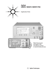
Agilent E8247C 250 kHz - 40 GHz PSG CW signal generator
Agilent E8257C 250 kHz - 40 GHz PSG analog signal generator
2
Table of Contents
Part 1:
Configuring the RF Output
2
Part 2:
Configuring Analog Modulation (E8257C Only)
20
Part 3:
Configuring the LF Output (E8257C Only)
22
Part 4:
Using Data Storage Functions
25
Part 5:
Using Table Editors
30
Part 6:
Configuring for Remote Control
31
Conventions used in this
demonstration
In this self guided demonstration
hard keys on the instrument front
panel are shown as [Hard Keys]. The
soft keys at the right of the display
are shown as {Soft Keys}. Items which
appear in the display area are
shown as DISPLAY. Front panel
items are shown as FRONT PANEL.
Sequential commands are separated
by >.
3
Part 1:
Configuring the RF Output
This section explains how to
create continuous wave and
swept RF outputs.
Configuring a continuous wave
RF output
Using these procedures, you will
learn how to set the following
parameters:
• RF output frequency
• frequency reference and
frequency offset
• RF output amplitude
• amplitude reference and
amplitude offset
Setting the RF output frequency
Instruction
1. Press [Preset].
Note
This returns the signal generator to the
factory-defined instrument state.
NOTE
You can change the preset conditions to a
user-defined instrument state. However, these
examples, use the factory-defined preset state
(the {Preset Normal User} softkey in the Utility
menu must be set to Normal).
2. Observe the FREQUENCY area of the
display (in the upper left-hand corner).
The value displayed is the maximum specified
frequency of your signal generator.
3. Press [RF On/Off].
The [RF On/Off] hardkey must be pressed before
the RF signal is available at the RF OUTPUT
connector. The display annunciator changes from
RF OFF to RF ON. The maximum specified
frequency is now being output at the RF OUTPUT
connector (at –135.00 dBm).
4. Press [Frequency] > [700] > {MHz}.
The new 700 MHz RF frequency is now displayed in
the FREQUENCY area of the display and also in the
active entry area.
5. Press [Frequency] > [Incr Set] > [1] > {MHz}.
This changes the frequency increment value
to 1 MHz.
6. Press the up-arrow key.
Each press of the up-arrow key increases the
frequency by the increment value last set with the
[Incr Set] hardkey. The increment value is displayed
in the active entry area.
7. The down arrow works like the up arrow.
Practice stepping the frequency up and down in
1 MHz increments.
You can also adjust the RF output frequency using
the knob. As long as frequency is the active
function (the frequency is displayed in the active
entry area), the knob will increase and decrease the
RF output frequency.
8. Use the knob to adjust the frequency
back to 700 MHz.
4
Setting the frequency reference
and frequency offset
The following procedure sets the
RF output frequency as a reference
frequency to which all other frequency parameters are relative. The
frequency initially shown on the display will be 0.00 Hz (the frequency
output by the hardware minus the
reference frequency). Although the
display changes, the frequency
output does not change. Any subsequent frequency changes are shown
as incremental or decremental to
0 Hz.
Setting the RF output amplitude
Instruction
1. Press [Preset].
Note
2. Press [Frequency] > [700] > {MHz}.
3. Press {Freq Ref Set}.
This activates the frequency reference mode and
sets the current output frequency (700 MHz) as the
reference value. The frequency displayed is 0.00 Hz
(the frequency output by the hardware, 700 MHz,
minus the reference value, 700 MHz). The REF
indicator is activated and the {Freq Ref Off On}
softkey has toggled to On.
4. Press [RF On/Off].
The display annunciator has changed from RF OFF
to RF ON. The RF frequency at the RF OUTPUT
connector is 700 MHz.
5. Press [Frequency] > {Incr Set} > [1] > {MHz}.
This changes the frequency increment value
to 1 MHz.
6. Press the up arrow key.
This increments the output frequency by 1 MHz.
The frequency display changes to show 1 MHz
(the frequency output by the hardware,
700 MHz + 1 MHz, minus the reference frequency,
700 MHz) and the output frequency changes
to 701 MHz.
7. Press [Freq Offset] > [1] > {MHz}.
This enters a 1 MHz offset. The frequency display
shows 2.000 000 00 MHz (the frequency output by
the hardware, 701 MHz, minus the reference
frequency, 700 MHz, plus the offset, 1 MHz). The
OFFS indicator is activated. The frequency at the
RF OUTPUT connector is still 701 MHz.
Instruction
1. Press [Preset].
Note
2. Observe the AMPLITUDE area of the display
(in the upper middle of the display). The display
reads –135.00 dBm. This is the normal
preset RF output amplitude.
3. Press [RF On/Off].
The display annunciator changes from RF OFF to
RF ON. The RF signal is now being output at an
amplitude of –135 dBm at the RF OUTPUT
connector.
4. Press [Amplitude] > [–20] > {dBm}.
This changes the amplitude to –20 dBm. The new
–20 dBm RF output power is now displayed in the
AMPLITUDE area of the display and also in the
active entry area.
Amplitude is still the active function until you press
another front panel function key. You can also
change the amplitude using the up and down arrow
keys and the knob.
5. Practice changing the amplitude using
the arrow keys and the knob.
5
Setting the amplitude reference and
amplitude offset
The following procedure sets the
RF output power as an amplitude
reference to which all other amplitude parameters are relative. The
amplitude initially shown on the display will be 0 dB (the power output
by the hardware minus the reference power). Although the display
changes, the output power does
not change. Any subsequent power
changes are shown as incremental
or decremental to 0 dB.
6
Instruction
1. Press [Preset].
Note
2. Press [Amplitude] > [–20] > {dBm}.
3. Press [More (1 of 2)] > {Ampl Ref Set}.
This activates the amplitude reference mode and
sets the current output power (–20 dBm) as the
reference value. The AMPLITUDE area displays
0.00 dB (the power output by the hardware,
–20 dBm, minus the reference value, –20 dBm).
The REF indicator is activated and the
{Ampl Ref Off On} softkey has toggled to On.
4. Press [RF On/Off].
The display annunciator has changed from RF OFF
to RF ON. The power at the RF OUTPUT connector
is –20 dBm.
5. Use the up arrow key to increase the
output power by 10 dB.
The AMPLITUDE area displays 10.00 dB
(the power output by the hardware, –20 dBm plus
10 dBm, minus the reference power, –20 dBm)
and the output power changes to –10 dBm.
6. Press {Ampl Offset} > [10] > {dB}.
This enters a 10 dB offset. The AMPLITUDE area
displays 20.00 dB (the power output by the
hardware, –10 dBm; minus the reference power,
–20 dBm; plus the offset, 10 dB). The OFFS
indicator is activated. The power at the RF OUTPUT
connector is still –10 dBm.
Configuring a swept RF output
NOTE
The signal generator has two sweep
types: step and list.
Step sweep data cannot be saved to the instrument
state register or to the memory catalog. Step
sweep configurations are reset at preset or when
the signal generator’s line power is cycled.
Following an explanation of the differences between step sweep and list
sweep, you will learn two ways to
configure the signal generator’s RF
output to sweep a defined set of frequency, amplitude, and dwell time
points. You will create a step sweep
and then you will use these points
as the basis for a new list sweep.
Step sweep
Sweep data cannot be saved to the
instrument state register.
List sweep data cannot be saved within an
instrument state, but can be saved to the memory
catalog. For instructions on saving list sweep data,
see Storing Files in Part 4.
During swept RF output, the FREQUENCY and
AMPLITUDE areas of the signal generator’s
display are deactivated.
Step sweep allows you to enter RF output start and
stop frequencies and amplitudes, a number of
equally spaced points (steps) to dwell upon, and
the amount of dwell time at each point.
When a step sweep is activated, the signal
generator will sweep the RF output based on the
values entered for the parameters listed above. The
frequency, amplitude, or frequency and amplitude of
the RF output will sweep from the start amplitude/
frequency to the stop amplitude/frequency, dwelling
at equally spaced intervals defined by the [# Points]
softkey value for the configured step dwell time.
Step sweep provides a linear progression through
the start-to-stop frequency and/or amplitude values.
You can toggle the direction of the sweep up or down.
When the [Sweep Direction Down Up] softkey is set
to Up, values are swept from the start frequency/
amplitude to the stop frequency/amplitude. Set to
Down, values are swept from the stop frequency/
amplitude to the start frequency/amplitude.
NOTE
List Sweep
Step sweep data cannot be saved to the instrument
state register or to the memory catalog.
List sweep allows you to create a list of frequency,
amplitude, and dwell time values and sweep the RF
output based on the entires in the List Mode
Values table.
Unlike a step sweep that contains linear ascending/
decending frequency and amplitude values spaced
at equal intervals throughout the sweep, list sweep
frequencies and amplitudes can be entered at
unequal intervals and nonlinear ascending/
decending or random order.
For convenience, the List Mode Values table can be
can be configured based upon the values of a previously
configured step sweep. Each step sweep point’s
associated frequency, amplitude and dwell time
values are entered ino a row in the List Mode Values
table, as the following example illustrates.
7
Configuring and activating a single
step sweep
In this procedure, you will create a
step sweep with nine, equally spaced
points and the following parameters:
Instruction
1. Press [Preset].
Note
2. Press [Sweep/List].
This opens a menu of sweep softkeys.
3. Press {Sweep Repeat Single Cont}.
This toggles the sweep repeat from continuous
to single.
4. Press {Configure Step Sweep}.
• frequency range from 500 MHz to
600 MHz
5. Press {Freq Start} > [500] > {MHz}.
This changes the start frequency of
the step sweep to 500 MHz.
• amplitude from –20 dBm to 0 dBm
6. Press {Freq Stop} > [600] > {MHz}.
This changes the stop frequency of
the step sweep to 600 MHz.
7. Press {Ampl Start} > [–20] > {dBm}.
This changes the amplitude level for
the start of the step sweep.
8. Press {Ampl Stop} > [0] > {dBm}.
This changes the amplitude level for
the end of the step sweep.
9. Press {# Points} > [9] > {Enter}.
This sets the number of sweep points to nine.
10. Press {Step Dwell} > [500] > {msec}.
This sets the dwell time at each point to
500 milliseconds.
11. Press {Return} > {Sweep} > {Freq & Ampl}.
This sets the step sweep to sweep both frequency
and amplitude data. Selecting this softkey returns
you to the previous menu and turns on the
sweep function.
12. Press [RF On/Off].
The display annunciator changes from RF OFF to
RF ON.
13. Press {Single Sweep}.
A single sweep of the frequencies and amplitudes
configured in the step sweep is executed and
available at the RF OUTPUT connector. The
progression of the sweep is displayed by
a progress bar.
• dwell time 500 ms at each point
8
Activating continuous step sweep
Instruction
Press {Sweep Repeat Single Cont}.
Note
This toggles the sweep from single to continuous.
The SWEEP annunciator is activated indicating that
the signal generator is sweeping. The progression
of the sweep is displayed by a progress bar. A
continuous repetition of the frequencies and
amplitudes configured in the step sweep are now
available at the RF OUTPUT connector.
Configuring a list sweep using step
sweep data
Instruction
1. Press {Sweep Repeat Single Cont}.
Note
This toggles the sweep repeat from continuous to
single. The SWEEP annunciator is turned off. The
sweep will not occur until it is triggered.
2. Press {Sweep Type List Step}.
This toggles the sweep type from step to list.
3. Press {Configure List Sweep}.
This opens another menu displaying softkeys that
you will use to create the sweep points. The display
shows the current list data. (When no list has been
previously created, the default list contains one
point set to the signal generator’s maximum
frequency, an amplitude of –135 dBm, with a
dwell time of 2 ms.)
4. Press {More (1 of 2)} > {Load List From
Step Sweep} > {Confirm Load From Step Sweep}.
The points you defined in the step sweep are
automatically loaded into the list.
Instruction
1. Press the right arrow key twice.
Note
This highlights the dwell time value in row 1.
2. Press {More (2 of 2}) > {Edit Item}.
The dwell time for point 1 becomes the active
function.
3. Press [100] > {msec}.
This enters 100 ms as the new dwell time value for
row 1. Note that the next item in the table (in this
case, the frequency value for point 2) becomes
highlighted after you press the terminator softkey.
In this procedure, you will leverage
the step sweep points and change
the sweep information by editing
several points in the List Mode
Values table editor. For information
on using table editors, see Using
Table Editors in Part 5.
Editing list sweep points
4. Using the arrow keys, highlight the
frequency value in row 4.
5. Press {Edit Item} > [545] > {MHz}.
This changes the frequency value in row 4
to 545 MHz.
6. Highlight any column in the point 7 row
and press {Insert Row}.
This adds a new point between points 7 and 8.
A copy of the point 7 row is placed between
points 7 and 8, creating a new point 8, and
renumbering the successive points.
9
Instruction
7. Highlight the frequency item for point 8,
then press {Insert Item}.
Note
NOTE
During this process, several error messages are
generated to inform you that the frequency and
power (or power and dwell) lists are of unequal
size. You will correct this problem in the following
steps, however the ERR annunciator does not turn
off until you clear the error queue. To clear the error
queue and return to the List Mode Values table
editor, follow these steps.
a. Press [Utility] > [Error Info] >
[Clear Error Queue(s)].
This clears the error queue.
b. Press [Sweep/List] > [Configure List Sweep].
This returns you to the List Mode Values
table editor.
Pressing Insert Item shifts frequency values down
one row, beginning at point 8. Note that the original
frequency values for both points 8 and 9 shift down
one row, creating an entry for point 10 that contains only a frequency value (the power and dwell
time items do not shift down).
The frequency for point 8 is still active.
8. Press [590] > {MHz}.
Activating List Sweep for
a Single Sweep
10
9. Press {Insert Item} > [–2.5] > {dBm}.
This inserts a new power value at point 8 and shifts
down the original power values for points 8 and 9
by one row.
10. Highlight the dwell time for point 9,
then press {Insert Item}.
A duplicate of the highlighted dwell time is inserted
for point 9, shifting the existing value down to
complete the entry for point 10.
Instruction
1. Press {Single Sweep}.
Note
The signal generator will sweep the points in your
list once. The SWEEP annunciator is activated
during the sweep.
2. Press {More (1 of 2)} > {Sweep Trigger} >
[Trigger] hardkey.
This sets the sweep trigger to occur when you
press the Trigger hardkey.
3. Press {More (2 of 2)} > {Single Sweep}.
This arms the sweep. The ARMED annunciator
is activated.
4. Press the [Trigger] hardkey.
The signal generator will sweep the points in your
list once and the SWEEP annunciator is activated
during the sweep.
Part 2: Configuring Analog Modulation
(E8257C Only)
The 8257C can modulate the RF carrier with four types of analog modulation: amplitude, frequency, phase,
and pulse.
AM, FM, and ΦM Sources
• AM, FM, and ΦM have two source
paths each. These multiple source
paths are summed internally for
composite modulation of the RF output.
• Each path can be fed by one of four
sources: Internal 1, Internal 2,
External 1 or External 2.
• Only one path can be active for each
source. For example, if AM Path 1 is
on and AM Path 1 source is set to
Internal 1, if AM Path 2 is on, AM
Path 2 source must be set to
Internal 2, External 1 or External 2.
Different paths cannot use the same
source at the same time.
• Waveforms available from Internal 1
and Internal 2 include:
Sine
sine wave with adjustable amplitude
and frequency
Dual-Sine
dual sine waves with individually
adjustable frequencies and a percent-of- peak-amplitude setting for
the second tone (available from
function generator 1 only)
Swept-Sine
a swept sine wave with adjustable
start and stop frequencies, sweep
time, and sweep trigger settings
(available from function generator 1
only)
Ramp
ramp with adjustable amplitude and
frequency
Square
square wave with adjustable amplitude and frequency
Noise
noise, in a uniform or Gaussian distribution, with adjustable amplitude
generated as a peak-to-peak value
(RMS value is approximately 80% of
the displayed value)
DC
direct current with adjustable amplitude
Pulse Sources
The following list summarizes the
different sources available for pulse
modulation.
External Pulse
modulates an external pulse signal
connected to the signal generator’s
PULSE/TRIGGER GATE INPUT connector.
Internal Gated
produces an internal, gated, pulse
modulation. When a valid gate signal
is applied to the TRIGGER IN connector, a pulse train (with userdefined width and pulse repetition
frequency parameters) will occur at
the RF OUTPUT connector.
Internal Trigger
produces an internal, triggered,
pulse modulation. An RF pulse (with
user-defined width and delay parameters) will occur at the RF OUTPUT
connector whenever a valid trigger
signal occurs at the TRIGGER IN
connector.
Internal Square
produces internal, square, pulse
modulation. The internal source is a
sinewave which is later squared by
the modulator to generate the pulse
squarewave with a duty cycle set to
50 percent.
Internal Pulse
produces internal, rectangular, pulse
modulation with with user-defined
width and period parameters.
Internal Doublet
produces two pulses at the RF OUTPUT connector for each trigger event
at the TRIGGER IN connector. The
first pulse will follow the external
trigger signal. The second pulse will
have user-defined delay and width
parameters.
Internal Free-Run
produces internal, free-run, pulse
modulation with user-defined period, width, and delay.
Triangle
triangle wave with adjustable amplitude and frequency
11
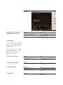
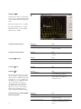
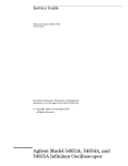
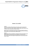
Configuring AM
Figure 1:
AM
Using this procedure, you will learn
how to create a multipath amplitude-modulated RF carrier with the
following characteristics:
• RF output frequency set to 4 GHz
• RF output amplitude set to 0 dBm
• AM Path 1 depth set to 90 percent
• AM Path 1 rate set to 10 kHz
• AM Path 1 waveform set to sine
• AM Path 2 depth set to 40 percent
• AM Path 2 waveform set to
triangle
• AM Path 2 rate set to 5 kHz
Setting the RF output frequency
Instruction
1. Press [Frequency] > [4] > {GHz}.
Note
The FREQUENCY area of the display now reads
4.000 000 000 00 GHz.
Setting the RF output amplitude
Instruction
1. Press [Amplitude] > [0] > {dBm}.
Note
The AMPLITUDE area of the display
now reads 0.00 dBm.
Setting the AM depth
Instruction
1. Press the [AM] hardkey.
Note
The first level menu of softkeys is displayed.
2. Press {AM Depth} > [90] > {%}.
90.0 % is displayed below the {AM Depth} softkey.
Setting the AM rate
Instruction
1. Press {AM Rate} > [10] > {kHz}.
Note
10.0000 kHz is displayed below the {AM Rate}
softkey.
Activating a AM configuration
Instruction
1. Press [AM Off On]
Note
2. Press [RF On/Off].
Viewing the signal on an Agilent E4440A
PSA spectrum analyzer
Instruction
1. Press [Preset].
Note
2. Press [Frequency] > [4] > {GHz}.
The Center FREQUENCY area of the display now
reads 4.000 000 00 GHz.
3. Press [Span] > [40] > {kHz}
The Span are of the display now reads 40 kHz.
The display on the PSA should now match Figure 1.
12
Creating a multipath
AM configuration
Use these steps to configure a multipath AM configuration. AM Path 1
and AM Path 2 are summed internally for composite modulation.
Either path can be switched to any
one of the modulation sources
(internal 1 or 2, external 1 or 2),
though any given source can only be
routed to one modulation type.
Instruction
1. Press {AM Path 1 2} to toggle to AM Path 2.
Note
This opens a menu of softkeys where you can
define a second unique amplitude modulation
configuration.
2. Press {AM Depth} > [40] > {%}.
The AM Path 2 AM depth is set to 40.0 percent , as
displayed below the {AM Depth} softkey.
3. Press {AM Rate} > [5] > {kHz}.
5.0000 kHz is displayed below the {AM Rate}
softkey.
4. Press {More (1 of 2)} > {AM Waveform}
> {Triangle}.
The AM Path 2 AM waveform is set to Triangle,
as displayed below the {AM Waveform} softkey.
5. Press {More (2 of 2} > {AM Source} > {Internal 2}
The AM Path 2 AM source is set to Internal 2, as
displayed below the {AM Waveform} softkey.
Instruction
1. Press {AM Off On}.
Note
This activates the modulation on AM Path 2. The
AM annunciator is activated, indicating that you
have enabled amplitude modulation on AM Path 2.
2. Press {AM Path 1 2} > {Amp Off On}.
This toggles back to AM Path 1 and activates the
modulation on AM Path 1.
3. Press [RF On/Off].
The RF ON annuciator is activated, indicating that
the multipath AM signal is now available at the
RF OUTPUT connector.
Note that the AM Source for AM
Path 1 is set to Internal 1 as a
default setting. Therefore, the AM
Source for AM Path 2 must be set to
another source, as explained in the
following procedure.
Activating a multipath
AM configuration
The signal generator is now configured to output a 0 dBm, multipath
amplitude-modulated carrier at
4 GHz. AM Path 1 is set to an AM
depth of 90 percent, an AM rate of
10 kHz, and a sinewave as the
default AM waveform. AM Path 2 is
set to an AM depth of 40 percent
with a triangle
AM waveform at the rate of 5 kHz.
Follow these remaining steps to output the amplitude-modulated signal.
13
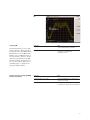
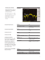
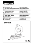
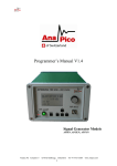
Figure 2:
Multipath AM
Viewing the signal on an Agilent
E4440A PSA spectrum analyzer
Instruction
1. Press [Preset].
Note
2. Press [Frequency] > [4] > {GHz}.
The Center FREQUENCY area of the display now
reads 4.000 000 00 GHz.
3. [Press Span] > [40] > {kHz}.
The Span are of the display now reads 40 kHz.
The display on the PSA should now match Figure 2
Configuring FM
Using this procedure, you will learn
how to create a frequency-modulated RF carrier with the following
characteristics:
• RF output frequency set to 4 GHz
• RF output amplitude set to 0 dBm
• FM deviation set to 75 kHz
• FM rate set to 10 kHz
Setting the RF output frequency
Instruction
1. Press [Preset].
Note
2. Press [Frequency] > [4] > {GHz}.
The FREQUENCY area of the display now reads
4.000 000 000 00 GHz.
Setting the RF output amplitude
Instruction
1. Press [Amplitude] > [0] > {dBm}.
Note
The AMPLITUDE area of the display
now reads 0.00 dBm.
Setting the FM deviation
Instruction
1. Press [FM/ΦM].
Note
The first level menu of FM softkeys is displayed.
2. Press {FM Dev} > [75] > {kHz}.
75.0000 kHz is displayed below the {FM Dev}
softkey.
Instruction
1. Press {FM Rate} > [10] > {kHz}.
Note
10.0000 kHz is displayed below the
{FM Rate} softkey.
Setting the FM rate
14
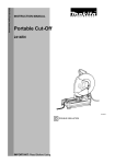
Figure 3:
FM
Activating FM
The signal generator is now configured to output a 0 dBm, frequencymodulated carrier at 4 GHz with the
FM deviation set to 75 kHz and the
FM rate set to 10 kHz. The shape of
the waveform is a sinewave. (Notice
that sine is the default for the FM
Waveform softkey. Press More (1 of
2) to see the softkey.) Follow these
remaining steps to output the frequency-modulated signal.
Viewing the signal on an Agilent E4440A
PSA spectrum analyzer
Instruction
1. Press [FM Off On].
Note
The FM annunciator is activated, indicating that
you have enabled frequency modulation.
2. Press [RF On/Off].
The RF ON annuciator is activated, indicating that
the signal is now available at the
RF OUTPUT connector.
Instruction
1. Press [Preset].
Note
2. Press [Frequency] > [4] > {GHz}.
The Center FREQUENCY area of the display now
reads 4.000 000 00 GHz.
3. Press [Span] > [350] > {kHz}.
The Span area of the display now reads 350 kHz.
The display on the PSA should now match Figure 3.
15
Configuring ΦM
Figure 4:
ΦM
Using this procedure, you will learn
how to create a phase-modulated RF
carrier with the following characteristics:
• RF output frequency set to 4.0 GHz
• RF output amplitude set to 0 dBm
•ΦM deviation set to 0.25 l radians
• ΦM rate set to 30 kHz
Setting the RF output frequency
Instruction
1. Press [Preset].
Note
2. Press [frequency] > [4] > {GHz}.
The FREQUENCY area of the display now reads
4.000 000 000 00 GHz.
Setting the RF output amplitude
Instruction
1. Press [Amplitude] > [0] > {dBm}.
Note
The AMPLITUDE area of the display now reads
0.00 dBm.
Setting the ΦM deviation
Instruction
1. Press the [FM/ΦM] hardkey.
Note
2. Press the {FM ΦM} softkey.
The first level menu of ΦM softkeys is displayed.
3. Press {ΦM Dev} > [.25] > [pi rad].
This changes the ΦM deviation to 0.25 l radians.
Setting the ΦM rate
Instruction
1. Press {ΦM Rate} > [10] > {kHz}.
Note
This sets the ΦM rate to 10 kHz.
Activating ΦM
Instruction
1. Press {ΦM Off On}.
Note
The ΦM annunciator is activated, indicating that
you have enabled phase modulation.
2. Press [RF On/Off].
The RF ON annuciator is activated, indicating
that the signal is now available at the
RF OUTPUT connector.
Instruction
1. Press [Preset].
Note
2. Press [Frequency] > [4] > {GHz}.
The Center FREQUENCY area of the display now
reads 4.000 000 00 GHz.
3. Press [Span] > [100] > {kHz}.
The Span are of the display now reads 100 kHz.
The signal generator is now configured to output a 0 dBm, phase-modulated carrier at 4 GHz with the ΦM
deviation set to 0.25 – radians and
the ΦM rate set to 10 kHz. The shape
of the waveform is a sinewave.
(Notice that sine is the default for
the ΦM Waveform softkey. Press
[More (1 of 2)] to see the softkey.)
Follow these remaining steps to
output the phase-modulated signal.
Viewing the signal on an Agilent E4440A
PSA spectrum analyzer
16
The display on the PSA should now match
Figure 4.
Configuring pulse modulation
Figure 5:
Pulse Modulation
Using the following procedure you
will learn how to create a pulsemodulated RF carrier with the following characteristics:
• RF output frequency set to 4 GHz
• RF output amplitude set to 0 dBm
• pulse period set to 100.0 µsec
• pulse width set to 24.0 µsec
• pulse source set to internal
free-run
Instruction
1. Press [Preset].
Note
2. Press [frequency] > [4] > {GHz}.
The FREQUENCY area of the display now reads
4.000 000 000 00 GHz.
Setting the RF output amplitude
Instruction
1. Press [Amplitude] > [0] > {dBm}.
Note
The AMPLITUDE area of the display now reads
0.00 dBm.
Setting the pulse period
Instruction
1. Press [Pulse] > {Pulse Period} > [100] > {µsec}.
Note
This sets the pulse period to 100 microseconds.
Setting the pulse width
Instruction
1. Press [Pulse] > {Pulse Width} > [1] > {µsec}.
Note
This sets the pulse period to 1 microseconds.
Activating pulse modulation
The signal generator is now configured to output a 0 dBm, pulse-modulated carrier at 4 GHz with the
pulse period set to 100 microseconds and the pulse width set to
24 microseconds. The pulse source
is set to internal free-run. (Notice
that internal free-run is the default
for the Pulse Source softkey.) Follow
these remaining steps to output the
pulse-modulated signal.
Instruction
1. Press {Pulse Off On}.
Note
This activates pulse modulation. The Pulse
annunciator is activated indicating that you have
enabled pulse modulation.
2. Press [RF On/Off].
The RF ON annuciator is activated, indicating that
the signal is now available at the RF OUTPUT
connector.
Viewing the signal on a Agilent E4440A
PSA spectrum analyzer
Instruction
1. Press [Preset].
Note
2. Press [frequency] > [4] > {GHz}.
The Center FREQUENCY area of the display now
reads 4.000 000 00 GHz.
3. Press [Span] > [5] > {MHz}.
The Span are of the display now reads 5 MHz.
4. Press [BW/Avg] > [Res BW] > [10] > {kHz}.
The display on the PSA should now match Figure 5.
Setting the RF output frequency
17
Part 3: Configuring the LF Output
(E8257C Only)
The E8257C has a low frequency
(LF) output. The LF output’s source
can be switched between an internal
modulation source (internal monitor
1 or 2) or an internal function generator (function generator 1 or 2).
Using internal monitor 1 or 2 as
the LF output source, the LF output
provides a replica of the signal from
either internal source (1 or 2) that is
being used to modulate the RF output. The specific modulation parameters for this signal are configured
through the AM, FM, or ΦM menus.
Using function generator 1 or 2 as
the LF output source, the function
generator section of the internal
modulation source (1 or 2) drive the
LO output directly. frequency and
waveform are configured from the
LF output menu, not through the
AM, FM, or ΦM menus. You can
select the waveform shape from
the following choices:
18
Sine
sine wave with adjustable amplitude
and frequency
Square
square wave with adjustable
amplitude and frequency
Dual-Sine
dual sine waves with individually
adjustable frequencies and a percent-of- peak-amplitude setting for
the second tone (available from
function generator 1 only)
Noise
noise, in a uniform or Gaussian distribution, with adjustable amplitude
generated as a peak-to-peak value
(RMS value is approximately 80% of
the displayed value)
Swept-Sine
a swept sine wave with adjustable
start and stop frequencies, sweep
time, and sweep trigger settings
(available from function generator 1
only)
DC
direct current with adjustable
amplitude
Triangle
triangle wave with adjustable
amplitude and frequency
Ramp
ramp with adjustable amplitude
and frequency
NOTE The {LF Out Off On} softkey
controls the operating state of the
LF output when the LF output
source is set to function generator 1
or 2. The {Mod On/Off} softkey
controls the operating state of the
LF OUTPUT connector when the
LF output source is set to internal
monitor 1 or 2.
The {RF On/Off} softkey does not
apply to the LF OUTPUT connector.
Configuring the LF output with an
internal modulation source
In this example, the internal FM
modulation is the LF output source.
Configuring the internal modulation as
the LF output source
Instruction
1. Press [Preset].
Note
2. Press the [FM/ΦM] hardkey.
Configuring the Low frequency output
3. Press {FM Dev} > [75] > {kHz}.
This sets the FM deviation to 75 kHz.
4. Press {FM Rate} > [10] > {kHz}.
This sets the FM rate to 10 kHz.
5. Press {FM Off On}.
The FM annunciator is activated indicating that you
have enabled frequency modulation.
Instruction
1. Press the [LF Out] hardkey.
Note
This opens the Low frequency output menu.
The LF output source is set to internal modulation 1
by default.
2. Press {LF Out Amplitude Into 50 Ω} > [3] > {Vp}.
This sets the LF output amplitude to 3 Vp.
3.000 Vp is displayed below the {LF Out Amplitude}
softkey.
3. Press {LF Out Off On}.
The LF output is a 3 Vp frequency modulated
sinewave (the default signal shape), with FM
deviation set to 75 kHz and FM rate set to 10 kHz.
Instruction
1. Press [Preset].
Note
Configuring the LF output with a
function generator source
In this example, function generator
1 is the LF output source.
Configuring the function generator as
the LF output source
2. Press the [LF Out] hardkey.
Configuring the waveform
Configuring the low frequency output
3. Press {LF Out Source} > {Function Generator 1}.
Function generator 1 becomes the LF output source
and FuncGen 1 is displayed below the
{LF Out Source} softkey.
Instruction
1. Press {LF Out Waveform} > {Swept-Sine}.
Note
This creates a swept-sine output and opens a
menu that configures the sweep parameters of the
swept-sine signal.
2. Press {LF Out Start Freq} > [100] > {Hz}.
This sets the swept-sine start frequency to 100 Hz.
3. Press {LF Out Stop Freq} > [1] > {kHz}.
This sets the swept-sine stop frequency to 1 kHz.
4. Press {LF Out Sweeps/Second} > [350] > {Hz}.
This sets the swept-sign sweeps-per-second
to 350.
5. Press {Return} > {Return}.
This returns you to the LF output menu. The start
frequency for the swept-sine waveform is displayed
below the {LF Out Freq} softkey.
Instruction
1. Press {LF Out Amplitude Into 50 Ohms} > [3] > {Vp}.
Note
This sets the LF output amplitude to 3 Vp.
2. Press {LF Out Off On}.
This activates the LF output. The LF output is a
3 Vp swept-sine waveform, sweeping from
100 Hz to 1 kHz with a sweep rate of 350 Hz.
19
Part 4: Using Data
Storage Functions
This section explains how to use
the two forms of signal generator
data storage, the memory catalog, and the instrument state
register.
Using the memory catalog
The signal generator’s interface for
stored files is the memory catalog.
From there you can view, copy,
rename, and delete files, either from
the signal generator’s front panel or
via remote controller. (For information on performing these tasks
remotely, see the programming
guide.)
20
The memory catalog may contain
the following file types and their
associated data:
LIST
sweep data from the List Mode
Values table including frequency,
amplitude, and dwell time.
STAT
instrument state data, controlling
instrument operating state parameters, such as frequency, amplitude,
and mode.
UFLT
user flatness calibration correction
pair data (user-defined frequency
and corresponding amplitude
correction values).
Viewing stored files
Instruction
1. Press [Utility] > {Memory Catalog}
> {Catalog Type}.
Note
The default catalog type is All (all files in the
memory catalog are listed in alphabetical order,
regardless of type). When viewing all files, file
name listings include a pointer to their file type,
such as <file name>@STATE or <file name>@LIST.
2. Press [List].
The Catalog of List Files is displayed.
3. Press {Catalog Type} > {State}
The Catalog of State Files is displayed.
4. Press {Catalog Type} > {User Flatness}
The Catalog of USERFLAT Files is displayed.
Storing files
Instruction
1. Press [Preset].
Note
To store a file to the memory catalog, first create a file. For this example, use the default list sweep table.
2. Press {Sweep/List} > {Configure List Sweep}
> {More (1 of 2)} > {Load/Store}.
This opens the Catalog of List Files.
3. Press {Store to File}.
This displays a menu of alphabetical softkeys for
naming the file. Store to: is displayed in the active
function area.
4. Enter the file name LIST1 using the alphabetical
softkeys and the numeric keypad.
Copying stored files
5. Press {Enter}.
The file is now displayed in the Catalog of List Files,
including the file name, type, and size.
Instruction
1. Highlight the desired file.
Note
2. Press {Copy File}.
This opens the file naming text editor.
3. Press {Editing Keys} > {Clear Text}.
This clears the old file name.
4. Input the new file name using the alphabetical
softkeys and the numeric keypad.
5. Press {Enter}.
Renaming stored files
Instruction
1. Highlight the desired file.
Note
2. Press {More (1 of 2)} > {Rename File}.
3. Press {Editing Keys} > {Clear Text}.
4. Input the new file name using the alphabetical
softkeys and the numeric keypad.
5. Press {Enter}.
Deleting stored files
Instruction
1. Highlight the desired file.
Note
2. Press {Delete File}.
The {Confirm Delete} softkey appears.
3. Press {Confirm Delete}.
21
Using the instrument state register
The instrument state register is a
section of memory divided into
10 sequences (numbered 0 through
9), each containing 100 registers
(numbered 00 through 99). It is
used to store and recall frequency,
amplitude, and E8257C, modulation
settings. It provides a quick alternative to reconfiguring the signal generator via the front panel or SCPI
commands when switching between
different signal configurations. Once
an instrument state has been saved,
all of the frequency, amplitude, and
modulation settings can be recalled
with minimum effort.
NOTE List sweep data is not
saved within an instrument state.
For instructions on saving list
sweep data, refer to “Storing Files”
in Part 4, “Using Data Storage
Functions.”
Step sweep data cannot be saved to
the instrument state register or to
the memory catalog.
22
Saving an instrument state
Instruction
1. Press [Preset].
Using this procedure, you will
learn how to save current instrument settings to the instrument
state register.
2. Configure the signal generator
with the following settings:
Note
a. Press [Frequency] > [800] > {MHz}.
b. Press [Amplitude] > [0] > {dBm}.
c. Press [AM] > {AM Off On}.
This enables amplitude modulation
(AM annunciator is on).
3. Press [Save] > {Select Seq}.
The sequence number becomes the active function.
The signal generator displays the last sequence
that you have used. Set the sequence to 1 using
the arrow keys.
4. Press {Select Reg}.
The register number in sequence 1 becomes the
active function. The signal generator displays either
the last register used, accompanied by the text: (in
use), or (if no registers are in use) register 00,
accompanied by the text: (available). Use the arrow
keys to select register 01.
5. Press {Save Seq[1] Reg[01]}.
This will save this instrument state in sequence 1,
register 01 of the instrument state register.
6. Press {Add Comment to Seq[1] Reg[01]}.
This allows you to add a descriptive comment to
sequence 1 register 01. Enter your comment using
the alphanumeric softkeys and press Enter.
7. Press {Edit Comment In Seq[1] Reg[01]}.
This allows you to change the descriptive comment
for sequence 1 register 01, if desired. Change your
comment using the alphanumeric softkeys and
press Enter.
After making changes to an instrument state, you
may save it back to a specific register by highlighting
that register and pressing Re-SAVE Seq[n] Reg[nn].
Recalling an instrument state
Instruction
1. Press [Preset].
Note
Using this procedure, you will learn
how to recall instrument settings
saved to an instrument state
register.
2. Press the [Recall] hardkey.
Notice that the {Select Seq} softkey shows
sequence 1. (This is the last sequence that
you used.)
3. Press [RECALL Reg].
The register to be recalled in sequence 1 becomes
the active function. Press the up arrow key once to
select register 1. Your stored instrument state
settings have now been recalled.
23
Deleting registers and sequences
Using this procedure, you will learn
how to delete registers and
sequences saved to an instrument
state register.
To delete a specific register
within a sequence
Instruction
1. Press [Preset].
Note
2. Press the [Recall] or [Save] hardkey.
Notice that the {Select Seq} softkey shows the last
sequence that you used.
3. Press {Select Seq} and enter the sequence
number containing the register you want to delete.
To delete all registers within a sequence
4. Press {Select Reg} and enter the register number
you want to delete.
Notice that the Delete Seq[n] Reg[nn] is now
loaded with the sequence and register you
want to delete.
5. Press {Delete Seq[n] Reg[nn]}.
This deletes the chosen register.
Instruction
1. Press [Preset].
Note
2. Press the [Recall] or [Save] hardkey.
Notice that the {Select Seq} softkey shows the last
sequence that you used.
3. Press {Select Seq} and enter the sequence number
containing the registers you want to delete.
4. Press {Delete all Regs in Seq[n]}.
This deletes all registers in the selected sequence.
CAUTION This will delete the entire contents, all
registers and all sequences, contained in the
instrument state register.
To delete all sequences
24
Instruction
1. Press [Preset].
Note
2. Press the [Recall] or [Save] hardkey.
Notice that the {Select Seq} softkey shows the last
sequence that you used.
3. Press {Delete All Sequences}.
This deletes all of the sequences saved in the
instrument state register.
Part 5: Using Table Editors
The PSG signal generator uses table
editors to simplify configuration
tasks such as creating a list sweep.
Table Items
values arraigned in numbered rows
and titled columns
Delete Item
deletes the item from the bottom
row of the currently selected column
Using the List Mode Values table editor, the following section familiarizes you with basic table editor
functionality.
Table editor softkeys
Goto Row
opens a submenu of softkeys (Goto
Top Row, Goto Middle Row, Goto
Bottom Row, Page Up, and Page
Down) used to quickly navigate
through the table items
Press [Preset] > [Sweep/List] >
[Configure List Sweep].
The signal generator displays the
List Mode Values table editor, as
shown below.
Active Function Area
an area that displays the active table
item while its value is edited
Cursor
an inverse video identifier used to
highlight specific table items for
selection and editing
Table Editor Softkeys
keys that select table items, preset
table values and modify table
structures
Modifying items in the table editor
To modify existing table items,
follow these steps:
The following table editor softkeys
are used to load, navigate, modify,
and store table item values. Press
More (1 of 2) to view additional
table editor softkeys.
Edit Item
displays the selected item in the
active function area of the display
where the item’s value can be
modified
Insert Row
inserts an identical row of table
items above the currently selected
row
Delete Row
deletes the currently selected row
Insert Item
inserts an identical item in a new
row below the currently selected
item
Page Up and Page Down
display table items that occupy rows
outside the limits of the ten-row
table display area
Load/Store
opens a submenu of softkeys (Load
From Selected File, Store To File,
Goto Row, Page Up, and Page Down)
used to load table items from a file
in the memory catalog, or to store
the current table items as a file in
the memory catalog
For more information on loading
and storing files, “Using Data
Storage Functions.”
Instruction
1. Use the arrow keys or the knob to move the
table cursor over the desired item.
Note
2. Press [Edit Item].
The selected item is displayed in the active
function area of the display.
3. Use the knob, arrow keys, or the numeric keypad
to modify the value.
4. Press {Enter}.
The modified item is now displayed in the table.
25
Part 6: Configuring for
Remote Control
This section will show you how to
configure the signal generator to
interface with a remote controller.
Follow the instructions in the appropriate section to configure your PSG
signal generator for remote control.
NOTE For a complete system
interface required equipment list
and installation procedure, see the
programming guide.
Configuring for a parallel GPIB
(IEEE 488.2, 1987) interface
Selecting a GPIB Address
Instruction
Note
1. Press [Utility] > {GPIB/RS-232} > {GPIB Address}.
2. Use the numeric keypad, the arrow keys, or
rotate the front panel knob to set the desired address.
3. Press {Enter}.
The signal generator’s GPIB address is set to 19
at the factory. The acceptable range of addresses
is 0 through 30. The state of the GPIB address is
not affected by a signal generator preset or by
a power cycle.
Configuring for a LAN
(10-base T) interface
Instruction
Note
1. Press [Utility] > {GPIB/RS-232 LAN} > {LAN Setup}.
2. Press {Hostname}.
Use the alphanumeric softkeys to enter
a hostname.
3. Press {Enter}.
26
4. Press {IP Address}.
Use the left and right arrow keys to move the
cursor. Use the up and down arrow keys, the front
panel knob or the numeric keypad to enter an
IP address.
5. Press {Enter}.
This assigns a hostname and IP address to the
signal generator. The hostname and IP address are
not affected by an instrument preset or by a
power cycle.
Configuring for a serial (RS-232)
auxiliary interface
Instruction
1. Press [Utility] > {GPIB/RS-232 LAN} >
{RS-232 Setup}.
Note
2. Press {RS-232 Baud Rate}.
Press the desired baud rate softkey to set the
baud rate.
3. Press {RS-232 Echo Off On}.
This toggles the state of the SCPI echoing on the
RS-232 connection. Set as desired.
4. Press {Trans/Recv Pace None Xon}.
This toggles from no handshaking
(Trans/Recv Pace None) to XON/XOFF
handshaking (Trans/Recv Pace Xon) when
transmitting or receiving data via RS-232.
Set as desired.
5. Press {Reset RS-232}.
This deletes the data from the RS-232 buffer.
Pressing this key will discard any unprocessed
SCPI input received over RS-232.
These RS-232 parameters are not affected by an
instrument preset or by a power cycle.
27
Agilent Technologies’ Test and Measurement Support,
Services, and Assistance
To find out more visit:
www.agilent.com/find/psg
Related Agilent literature
PSG Signal Generator Brochure
Literature number 5988-7538EN
Agilent E8247/E8257C
PSG CW and Analog Signal
Generator Data Sheet
Literature number 5988-2412EN
Warranty
The standard warranty is three
years. An extended five-year warranty is available with Option W50.
Agilent Technologies aims to maximize the value you receive,
while minimizing your risk and problems. We strive to ensure
that you get the test and measurement capabilities you paid for
and obtain the support you need. Our extensive support
resources and services can help you choose the right Agilent
products for your applications and apply them successfully.
Every instrument and system we sell has a global warranty.
Support is available for at least five years beyond the production
life of the product. Two concepts underlie Agilent's overall support policy: "Our Promise" and "Your Advantage."
Our Promise
Our Promise means your Agilent test and measurement equipment will meet its advertised performance and functionality.
When you are choosing new equipment, we will help you with
product information, including realistic performance specifications and practical recommendations from experienced test
engineers. When you use Agilent equipment, we can verify that
it works properly, help with product operation, and provide basic
measurement assistance for the use of specified capabilities, at
no extra cost upon request. Many self-help tools are available.
Your Advantage
Agilent E8267C
PSG Vector Signal Generator
Data Sheet
Literature number 5988-6632EN
Agilent E8267C
PSG Vector Signal Generator
Configuration Guide
Literature number 5988-7541EN
PSG Series Product Note:
Millimeter Head
Literature number 5988-2567EN
PSG Series Product Note:
Millimeter Head
Literature number 5988-2567EN
PSG Two-tone and Multi-tone
Application Note
Application Note 1410
Literature number 5988-7689EN
Digital Modulation in
Communications Systems–
An Introduction
Application Note 1298
Literature number 5965-7160EN
Your Advantage means that Agilent offers a wide range of additional expert test and measurement services, which you can
purchase according to your unique technical and business
needs. Solve problems efficiently and gain a competitive edge
by contracting with us for calibration, extra-cost upgrades, outof-warranty repairs, and onsite education and training, as well
as design, system integration, project management, and other
professional engineering services. Experienced Agilent engineers and technicians worldwide can help you maximize your
productivity, optimize the return on investment of your Agilent
instruments and systems, and obtain dependable measurement
accuracy for the life of those products.
www.agilent.com/find/emailupdates
Get the latest information on the products and applications you
select.
Agilent T&M Software and Connectivity
Agilent's Test and Measurement software and connectivity
products, solutions and developer network allows you to take
time out of connecting your instruments to your computer with
tools based on PC standards, so you can focus on your tasks,
not on your connections. Visit www.agilent.com/find/connectivity for more information.
By internet, phone, or fax, get assistance
with all your test & measurement needs
Online assistance:
www.agilent.com/find/assist
Phone or Fax
United States:
(tel) 800 452 4844
Canada:
(tel) 877 894 4414
(fax) 905 282 6495
China:
(tel) 800 810 0189
(fax) 800 820 2816
Europe:
(tel) (31 20) 547 2323
(fax) (31 20) 547 2390
Japan:
(tel) (81) 426 56 7832
(fax) (81) 426 56 7840
Korea:
(tel) (82 2) 2004 5004
(fax) (82 2) 2004 5115
Latin America:
(tel) (305) 269 7500
(fax) (305) 269 7599
Taiwan:
(tel) 0800 047 866
(fax) 0800 286 331
Other Asia Pacific
Countries:
(tel) (65) 6375 8100
(fax) (65) 6836 0252
Email:
[email protected]
Product specifications and descriptions in this
document subject to change without notice.
© Agilent Technologies, Inc. 2001, 2002
Printed in USA October 08, 2002
5988-2414EN