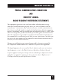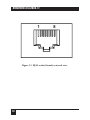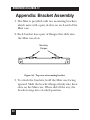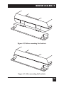
1
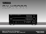
MAY 1998
MX873A
Miniature Local Mux-12
SS
POWER
SYNC LO
C
TEST REM LO
INPUT
9V-DC
CUSTOMER SUPPORT INFORMATION
Order toll-free in the U.S.: Call 877-877-BBOX (outside U.S. call 724-746-5500)
FREE technical support 24 hours a day, 7 days a week: Call 724-746-5500 or fax 724-746-0746
Mailing address: Black Box Corporation, 1000 Park Drive, Lawrence, PA 15055-1018
Web site: www.blackbox.com • E-mail: [email protected]
MINIATURE LOCAL MUX-12
FEDERAL COMMUNICATIONS COMMISSION
AND
INDUSTRY CANADA
RADIO FREQUENCY INTERFERENCE STATEMENTS
This equipment generates, uses, and can radiate radio-frequency energy,
and if not installed and used properly, that is, in strict accordance with the
manufacturer’s instructions, may cause interference to radio communication.
It has been tested and found to comply with the limits for a Class A computing
device in accordance with the specifications in Subpart B of Part 15 of FCC rules,
which are designed to provide reasonable protection against such interference
when the equipment is operated in a commercial environment. Operation of
this equipment in a residential area is likely to cause interference, in which case
the user at his own expense will be required to take whatever measures may be
necessary to correct the interference.
Changes or modifications not expressly approved by the party responsible
for compliance could void the user’s authority to operate the equipment.
This digital apparatus does not exceed the Class A limits for radio noise emission from
digital apparatus set out in the Radio Interference Regulation of Industry Canada.
Le présent appareil numérique n’émet pas de bruits radioélectriques dépassant les limites
applicables aux appareils numériques de classe A prescrites dans le Règlement sur le
brouillage radioélectrique publié par Industrie Canada.
1
MINIATURE LOCAL MUX-12
NORMAS OFICIALES MEXICANAS (NOM)
ELECTRICAL SAFETY STATEMENT
INSTRUCCIONES DE SEGURIDAD
1. Todas las instrucciones de seguridad y operación deberán ser leídas antes
de que el aparato eléctrico sea operado.
2. Las instrucciones de seguridad y operación deberán ser guardadas para
referencia futura.
3. Todas las advertencias en el aparato eléctrico y en sus instrucciones de
operación deben ser respetadas.
4. Todas las instrucciones de operación y uso deben ser seguidas.
5. El aparato eléctrico no deberá ser usado cerca del agua—por ejemplo,
cerca de la tina de baño, lavabo, sótano mojado o cerca de una alberca,
etc..
6. El aparato eléctrico debe ser usado únicamente con carritos o pedestales
que sean recomendados por el fabricante.
7. El aparato eléctrico debe ser montado a la pared o al techo sólo como sea
recomendado por el fabricante.
8. Servicio—El usuario no debe intentar dar servicio al equipo eléctrico más
allá a lo descrito en las instrucciones de operación. Todo otro servicio
deberá ser referido a personal de servicio calificado.
9. El aparato eléctrico debe ser situado de tal manera que su posición no
interfiera su uso. La colocación del aparato eléctrico sobre una cama,
sofá, alfombra o superficie similar puede bloquea la ventilación, no se
debe colocar en libreros o gabinetes que impidan el flujo de aire por los
orificios de ventilación.
2
MINIATURE LOCAL MUX-12
10. El equipo eléctrico deber ser situado fuera del alcance de fuentes de calor
como radiadores, registros de calor, estufas u otros aparatos (incluyendo
amplificadores) que producen calor.
11. El aparato eléctrico deberá ser connectado a una fuente de poder sólo del
tipo descrito en el instructivo de operación, o como se indique en el
aparato.
12. Precaución debe ser tomada de tal manera que la tierra fisica y la
polarización del equipo no sea eliminada.
13. Los cables de la fuente de poder deben ser guiados de tal manera que no
sean pisados ni pellizcados por objetos colocados sobre o contra ellos,
poniendo particular atención a los contactos y receptáculos donde salen
del aparato.
14. El equipo eléctrico debe ser limpiado únicamente de acuerdo a las
recomendaciones del fabricante.
15. En caso de existir, una antena externa deberá ser localizada lejos de las
lineas de energia.
16. El cable de corriente deberá ser desconectado del cuando el equipo no
sea usado por un largo periodo de tiempo.
17. Cuidado debe ser tomado de tal manera que objectos liquidos no sean
derramados sobre la cubierta u orificios de ventilación.
18. Servicio por personal calificado deberá ser provisto cuando:
A:
El cable de poder o el contacto ha sido dañado; u
B:
Objectos han caído o líquido ha sido derramado dentro del
aparato; o
C:
El aparato ha sido expuesto a la lluvia; o
D:
El aparato parece no operar normalmente o muestra un cambio en
su desempeño; o
E:
El aparato ha sido tirado o su cubierta ha sido dañada.
3
MINIATURE LOCAL MUX-12
TRADEMARKS USED IN THIS MANUAL
Any trademarks mentioned in this manual are acknowledged
to be the property of the trademark owners.
4
MINIATURE LOCAL MUX-12
Contents
Chapter
Page
1. Specifications. . . . . . . . . . . . . . . . . . . . . . . . . . . . . . . 7
1.1 Sub Channels. . . . . . . . . . . . . . . . . . . . . . . . . . . . 7
1.2 Main Channel . . . . . . . . . . . . . . . . . . . . . . . . . . . 8
1.3 General . . . . . . . . . . . . . . . . . . . . . . . . . . . . . . . . 8
2. Introduction . . . . . . . . . . . . . . . . . . . . . . . . . . . . . . . 10
2.1 General . . . . . . . . . . . . . . . . . . . . . . . . . . . . . . . . 10
2.2 Functional Description . . . . . . . . . . . . . . . . . . . . 10
2.3 Applications . . . . . . . . . . . . . . . . . . . . . . . . . . . . . 11
3. Installation. . . . . . . . . . . . . . . . . . . . . . . . . . . . . . . . . 14
3.1 General . . . . . . . . . . . . . . . . . . . . . . . . . . . . . . . . 14
3.2 Physical Installation. . . . . . . . . . . . . . . . . . . . . . . 14
3.3 Site Preparation. . . . . . . . . . . . . . . . . . . . . . . . . . 14
3.4 Setup . . . . . . . . . . . . . . . . . . . . . . . . . . . . . . . . . . 14
3.5 Electrical Installation . . . . . . . . . . . . . . . . . . . . . 16
5
MINIATURE LOCAL MUX-12
Contents (continued)
Chapter
Page
4. Operation . . . . . . . . . . . . . . . . . . . . . . . . . . . . . . . . . 20
4.1 General . . . . . . . . . . . . . . . . . . . . . . . . . . . . . . . . 20
4.2 Indicators . . . . . . . . . . . . . . . . . . . . . . . . . . . . . . . 20
4.3 Operating Procedure . . . . . . . . . . . . . . . . . . . . . 20
4.3.1 Powering On the Unit . . . . . . . . . . . . . . . 20
4.3.2 Operation . . . . . . . . . . . . . . . . . . . . . . . . . 21
4.3.3 Powering Off the Unit . . . . . . . . . . . . . . . 21
4.4 Operational Field Strapping Changes. . . . . . . . 21
5. Diagnostics. . . . . . . . . . . . . . . . . . . . . . . . . . . . . . . . . 22
5.1 Remote Loopback . . . . . . . . . . . . . . . . . . . . . . . . 22
5.2 Fault Isolation and Troubleshooting. . . . . . . . . 23
Appendix: Bracket Assembly . . . . . . . . . . . . . . . . . . . . 24
6
MINIATURE LOCAL MUX-12
1. Specifications
1.1 Sub-Channels
Transmission Format—Asynchronous
Mode of Operation—Full duplex
Data Rate—Up to 19.2 kbps
Interface—EIA RS-232/CCITT V.24
Connectors—(12) RJ-45 female
Number of Sub-channels—12
Distortion—See Table 1-1. User may select six subchannel operation for reduced distortion by internal
strapping.
Table 1-1. Performance at various bit rates.
Sub-channel
Distortion (%)
Distortion (%)
bit rate (Kbps)
6-channel mode
12-channel mode
19.2
9.6
4.8
2.4
1.2
12.5
6.3
3.2
1.6
0.8
25
12.5
6.3
3.2
1.6
7
MINIATURE LOCAL MUX-12
1.2 Main Channel
Transmission Line—4-wire unconditioned telephone
lines (two twisted pairs)
Operating Range—1 mile (1.6 km) maximum on
22 AWG cable (actual distance may vary, depending
on the cable you use)
Data Rate—1.2288 Mbps
Output Format—Balanced bipolar transformer isolated
Output Level—6 V ptp (on 100 ohms)
Input Resistance—110 ohms
Connectors—(1) RJ-45 female
1.3 General
Indicators—Power, Local Sync Loss, Remote Sync Loss
Table 1-2. Indicators.
Indicator
Function
Power
Local Sync Loss
Remote Sync Loss
Test
ON when unit is powered.
ON when synchronization is lost at the local Mux.
ON when synchronization is lost at the remote Mux.
ON when remote Mux is performing a loopback.
8
MINIATURE LOCAL MUX-12
Temperature—32 to 122°F (0 to 50°C)
Humidity—Up to 95%, noncondensing
Power Consumption—Input: 110 VAC, Output: 200 mA
@ 9 VDC
Size—1.3"H x 4.5"W x 7.4"D (3.4 x 11.4 x 18.7 cm)
Weight—10.7 oz. (300 g)
9
MINIATURE LOCAL MUX-12
2. Introduction
2.1 General
The Miniature Local Mux-12 is a time-division
multiplexor that enables up to 12 terminals to be
multiplexed onto a single cable, in point-to-point
applications. The Mux-12 contains a built-in line driver
that extends the high-speed multiplexed data over
twisted pairs.
2.2 Functional Description
The Mux-12 has 12 sub-channels that are connected by
RJ-45 connectors accessible from the top panel. The unit
can be strapped for 6 or 12 sub-channels according to
the desired application.
Multiplexing is implemented using an over-sampling
technique that enables each one of the 12 channels to
be sampled at a rate of 78.6 kbps. This technique results
in oversampling distortions, with a magnitude
proportional to the bit rate of the sub-channel. Table 2-1
summarizes the performance at various speeds and
modes of operation.
10
MINIATURE LOCAL MUX-12
NOTE
Whenever possible (when the number of channels is 6 or
less), we advise operating the Mux in the 6-channel mode,
which results in less distortion.
Table 2-1. Performance at various bit rates.
Sub-channel
Distortion (%)
Distortion (%)
bit rate (kbps)
6-channel mode
12-channel mode
19.2
9.6
4.8
2.4
1.2
12.5
6.3
3.2
1.6
0.8
25
12.5
6.3
3.2
1.6
2.3 Applications
The primary application of the Mux-12 is for point-topoint configurations at distances of up to 0.6 miles
(1 km). A typical application is demonstrated in Figure
2-1, where a cluster of terminals is connected to a host
computer through a single link.
11
MINIATURE LOCAL MUX-12
Miniature
Local Mux-12
Host
Terminals
Figure 2-1. Typical point-to-point installation.
For installations involving clusters of terminals
distributed in several locations, the Mux-12 units may be
installed in a ring-type configuration as shown in Figure
2-2. At each site, the unconnected channels must be
bypassed by shorting TX pin to RX pin of the relevant
sub-channel’s connector. Be aware that oversampling
distortions are accumulative, so this application limits
the bit rate of the sub-channels.
12
MINIATURE LOCAL MUX-12
Host
Miniature
Local Mux-12
Miniature
Local Mux-12
Terminals
Miniature Local
Mux-12
Terminals
Figure 2-2. Typical ring installation.
13
MINIATURE LOCAL MUX-12
3. Installation
3.1 General
This chapter provides the information you need to
implement the mechanical and electrical installation
of the Mux-12. After installation is complete, refer
to Chapter 4 for operating information and system
checkout to assure normal operation.
3.2 Physical Installation
The Mux-12 comes completely assembled and is
designed to be secured to a bench or wall using screws.
3.3 Site Preparation
The Mux-12 is installed within 5 ft. (1.5 m) of an AC
outlet enabling connection of the power-supply adapter.
3.4 Setup
Installation of the Mux is straightforward. First review
Table 2-1; the factory setting is for 12 sub-channels.
If this suits your requirements, you can skip steps 1
through 3 below.
14
MINIATURE LOCAL MUX-12
1. Open the top half of the plastic case by squeezing
the marked places on the sides.
2. Strap the multiplexor for 6 or 12 sub-channels
according to the printed circuit board.
3. To close the unit, simply press the two halves of the
case together.
4. Install the Mux within 5 ft. (1.5 m) of an AC outlet.
The unit can be wall-mounted by four screws
through the mounting brackets located at both
sides of the unit.
5. Connect 9 to 12 VDC from a wall-mounted AC
adapter into the DC jack of the Mux. The
“POWER” LED should be lit. Other LEDs may be
lit as well.
6. Connect the sub-channels to your equipment. Pin
assignment of the RJ-45 sub-channel connector is
given in Table 3-1. For a description of the RJ-45
connector, see Figure 3-2.
7. Connect the main channel of the Mux to the
wiring that connects it to the remote Mux. Pin
assignment of the RJ-45 main channel connector
is given in Table 3-2. Note that the Transmit Pair
15
MINIATURE LOCAL MUX-12
of one unit should be connected to the Receive
Pair of the other unit, and vice versa. All LEDs
should be “OFF” (with the exception of
“POWER”) indicating normal operation.
3.5 Electrical Installation
3.5.1 AC POWER
The Mux is powered by an external power supply of 9 to
12 VDC capable of supplying at least 300 mA. A
miniature wall-mount power supply can be used to
provide the required power. The power supply is
connected to the Mux by a cable ending with a
miniature 2 mm DC plug (tip positive, sleeve ground).
3.5.2 SUB-CHANNELS
Twelve RJ-45 8-pin jacks located on the top panel enable
end users to be connected to the unit. Detailed
information about the signals present at this jack and
pin configuration are given in Table 3-2 and Figure 3-2.
16
MINIATURE LOCAL MUX-12
Table 3-1. Sub-channel connector pin assignments.
CCITT V.24
EIA RS-232C
Pin No.
Signal Name
Description
102
103
AB
BA
7
5
Signal Ground
Transmit Data
104
BB
3
Receive Data
105
106
107
CA
CB
CC
2
8
6
Request to Send
Clear to Send
Data Set Ready
109
CF
4
Receive Line
Signal Detector
(Carrier Detect)
—
—
1
+V output
Common signal.
Serial data from
DTE into the Mux.
Serial data output
from the Mux
Connected to CTS.
Connected to RTS.
A positive level
from the Mux
except when either
a sync loss occurs
or remote loopback
is performed.
A positive level
from the Mux
except when either
a sync loss occurs
or remote loopback
is performed.
A positive
unregulated voltage
to power external
equipment (up to
120 mA total).
Table 3-2. Main channel’s connector pin assignment.
Pin No.
Signal Name
Description
1
2
7
8
RX-A
RX-B
TX-A
TX-B
Receive Pair
Transmit Pair
17
MINIATURE LOCAL MUX-12
1
8
Figure 3-1. RJ-45 socket (female) external view.
18
MINIATURE LOCAL MUX-12
1
8
Figure 3-2. RJ-45 plug (male) clip at rear.
19
MINIATURE LOCAL MUX-12
4. Operation
4.1 General
This chapter contains a list of the Mux-12’s indicators,
their functions and operating procedures. Installation
procedures given in Chapter 3 must be completed and
checked before attempting to operate the Mux.
4.2 Indicators
Four indicators are located on the Mux’s top panel (see
Figure 4-1). Their functions are described in Table 4-1.
Table 4-1. Indicator functions.
Indicator
Function
Power
Test
Local Sync Loss
Remote Sync Loss
ON when unit is powered
ON when remote Mux is performing a loopback
ON when synchronization is lost at the local unit
ON when synchronization is lost at the remote unit
4.3 Operating Procedure
4.3.1 POWERING ON THE UNIT
To power on the Mux, connect the power cable to the
Mux’s jack, then plug the power supply unit into the
mains. The POWER indicator should light. If the link to
20
MINIATURE LOCAL MUX-12
the remote Mux is still not operational, the SYNC LOSS
indicators should be lit.
4.3.2 OPERATION
The Mux operates entirely unattended except when
occasional monitoring of LED indicators is required.
4.3.3 POWERING OFF THE UNIT
To power off the Mux, simply remove the power adapter
from the AC source.
4.4 Operational Field Strapping Changes
If you need to reconfigure the Mux for 6- or 12-channel
mode, simply follow the appropriate setup procedure
given in Section 3.2.
21
MINIATURE LOCAL MUX-12
5. Diagnostics
5.1 Remote Loopback
Remote loopback can be performed by the Mux-12
when operated in conjunction with the single-port
Miniature Local Mux. The test is performed by pressing
the RLB button switch located on the front panel of the
single-port Mux, which results in looping data back from
the remote Mux-12’s receiver to the transmitter. The test
checks the single-port Mux’s digital circuitry as well as
both local and remote analog interfaces, the mainchannel link, and the Mux-12’s digital receiver section.
NOTE
When either local or remote loopback test is performed by
the single-port Mux, the TEST LED should be lit while all
other LEDs should be off at the remote Mux-12. At the
same time the Received Data signals (Circuit 104) at the
Mux-12’s sub-channels are set to MARK (negative voltage)
condition.
5.2 Fault Isolation and Troubleshooting
The symptoms and corresponding procedures listed in
Table 5-1 enable you to identify, isolate, and correct
faults.
22
MINIATURE LOCAL MUX-12
WARNING
These service instructions are for use by qualified
personnel only. To avoid shock, do not perform any
servicing other than that contained in the operating
instructions unless you are qualified to do so.
Table 5-1. Fault isolation and troubleshooting.
Symptom
Action
All front-panel
indicators are off
a) Check that power is supplied to the unit.
b) Replace unit. The fault is probably in the unit’s powersupply circuits.
Local SYNC LOSS and/or a) Check the main channel’s connection at both sites. Verify
REMOTE SYNC LOSS
that these connections are in accordance with the procedure
is ON
described in Section 3.4.7 and 3.5.3.
b) Replace both units: one at a time. If the problem still exists,
the main channel link between the units is probably defective
and should be checked.
23
MINIATURE LOCAL MUX-12
Appendix: Bracket Assembly
1. The Mux is provided with two mounting brackets,
which mate with a pair of slots on each end of the
Mux case.
2. Each bracket has a pair of flanges that slide into
the Mux case slots.
Mounting
Flanges
Figure A-1. Top view of mounting bracket.
3. To attach the brackets, hold the Mux case facing
upward. Slide the bracket flanges firmly into their
slots on the Mux case. When slid all the way, the
brackets snap into a locked position.
24
MINIATURE LOCAL MUX-12
Figure A-2. Before mounting the brackets.
Figure A-3. After mounting the brackets.
25
© Copyright 1998. Black Box Corporation. All rights reserved.
1000 Park Drive • Lawrence, PA 15055-1018 • 724-746-5500 • Fax 724-746-0746