1
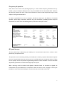
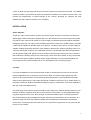
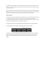
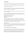
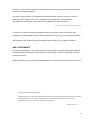
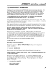
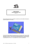
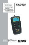
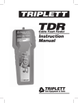
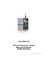
User Manual
RTcom-Universal, Global
Max and Outback
Radio Modems
Copyright Radio-Tech Limited 1998-2000
CONTENTS
INTRODCUTION
3
Selecting the frequency of operation
5
R.F Path Surveys
5
INSTALLATION
Power Supplies
6
Location
6
Antenna Feeders
7
Lightning Surge Protection
8
Antenna Installation
9
Antenna Options
10
GENERAL ARANGEMENT
RTcom-Global and Universal
11
RTcom-Outback
12
RTcom-Max
12
CONNECTIONS
Data and Power
13
CONFIGURATION
Operating Modes Table for the RTcom range
14
Data format mode switch
15
Interface mode switch
15
Data rate setting chart
15
OPERATION
Status LED's
16
All LED's Blinking
16
COMMISIONING
17
COMMUNICATION PROTOCOLS
The RTcom protocol
17
Using proprietary protocols
17
Using WindowsTM Terminal or Hyper Terminal
17
EMC Conformity
18
2
INTRODUCTION
The RTcom-range of radio modem is intended as a direct replacement for cables over short, medium
and long distance, serial data links. They are suitable for part of point-to-point, master to slave or
scanning telemetry links, where the modem is either used on its own our in conjunction with existing
cables. The modems also operate transparent to many industry standard network protocols, such as
Modbus and Eiba Bus and can be used with many manufacturers PLC communication protocols.
Serial Data
Serial Data
RTcom
Modem
RTcom
Modem
Fig 1: Simple point to point link
The advantages of wire free communication offered by Radio Modems such as Radio-Tech Universal,
Global, Europa, Outback and Max are numerous. These include reduced installation cost, the ability to
cross-awkward terrain, cross third parties lands, cross-rivers and operate from moving objects.
RTcom
Modem
Slave Station (1)
RTcom
Modem
Slave Station (2)
RTcom
Modem
Master station
Polled Master to multiple slave system
Thousands or RTcom radio modems are now in service throughout the world, many operating 24hrs a
day, all year round. However, for any radio communications system to be reliable care should be
taken in the design of the whole system. Many countries impose restrictions on the frequency, power,
channel power and occupied bandwidth of transmissions. Others in addition impose strict test and
certification procedures on equipment while others permit a free for all!
3
In many countries it is quite legal to operate systems without need for operating licences. These
countries include the United Kingdom, Australia, New Zealand, Korea, South Africa, Scandinavia and
the majority of Europe. However, operation in these countries is normally subject to the equipment first
being approved to a defined standard, such as the UK MPT1329 or the European ETS 300-220-1.
Other countries, such as the United States also permit unlicensed transmissions under FCC- Part 15,
but both the power and duty cycle limits imposed make modem operation impractical for reliable
operation over distance more than a few tens of meters.
Before using your RTcom Radio Modem please ensure that you have purchased the correct version
and selected the correct frequency of operation. We have versions with many international approvals
ranging from FCC-Part 90 through to Australia Standards and our European versions carry the CE
mark. If in doubt please ask your local Radio-Tech Limited agent.
4
Frequency of operation
Often there is not a choice over operating frequency. In most countries frequency allocations are very
limited, by way of example in Europe there is only 433-435MHz UHF or 868-870MHz SHF. While the
UK and many others offer VHF, UHF and SHF allocations. However other frequencies may be used
subject to local government licence.
In order to generalise the choice of frequency should be based upon the distance of intended
operation, power supply constraints, data rate, duty cycle, attenuation, portability (antenna size) and
the presence of other users. The following table is produced to assist your choice:-
VHF (10mW)
UHF (10mW)
UHF (500mW)
SHF (5mW)
Free Space Transmission
range
Industrial installation
In large buildings
Penetration through
concrete walls
Ability to bend/ defract
around obstructions
Antenna size (dipole)
Potential users in adjacent
channels
5-10km
3-5km
10-30km
100-200m
SHF
(500mW)*
*
5 - 10km
50-700m
50-500m
50m-1km
10-30m
30-100m
**********
****
******
*
**
**********
******
******
**
**
43cm
Message pagers
Radio Microphones
17cm
Radio
Amateur on
433MHz
8cm
CT2
Mobile
telephones
8cm
CT2
Mobile
Telephone
s
Transmission efficiency
For battery operation
Relative cost
**********
****
17cm
Radio
Amateurs on
433MHz
Message
Pages on
458MHz and
TETRA on
410-430MHz
****
***
***
***
*****
*****
*******
******
R.F path Surveys
The only certain way of determining the suitability of a communication channel is to conduct a radio
path survey and spectrum scan.
The spectrum scan is something normally conducted prior to ordering a system. Normally this requires
the use of a good quality scanning receiver such as an ICOM 8500 and a broadband antenna. Failure
to use a quality scanner may result in signals being missed if channel resolution is too low and false
signals being detected if co-channel and image rejection is poor.
When scanning, both the desired and adjacent channels should be checked for signals. As
transmissions may be intermittent it is important to take time with the scan, stopping for as long as
possible on each channel and looking for at least 15-minutes on the final chosen band.
5
If there is doubt over the signal reaching the receiver a path survey should be conducted. The outback
modem includes a test mode that places the modems transmitter into constant transmit mode. This
permits the measurement of signal strength at the receiver. Normally our modems will work
satisfactorily with a signal level below 1uV (-107dBm).
INSTALLATION
Power Supplies:
As with any radio communications system, the RTcom modem should be connected to a clean and
stable supply. Switch mode power supplies are rich in RF harmonics and should not be used. Please
note that in many cases as CE sticker on a power supply is insufficient protection against potentially
damaging harmonics. The reality is that the EMC pass limits are set at only -57dBm (316uV), whereas
a radio is quite capable of operation down to an beyond -115 dBm (0.5uV). Hence, a power supply is
capable of legally generating harmonics quite capable of blocking the modems operating channel. As
a word of warning the frequency of the offending harmonics can shift with both ambient temperature,
time and power supply load. Please do not be fooled into thinking that a system fine only to find that
later it fails due to blocking from its own power supply. Hence as a rule of thumb we only recommend
the use of linear power supplies. Similarly where supply interruption is to be protected against, we
recommend the use of float charged (12V or 24V dc) batteries and not switching UPS's.
Location:
For indoor installations we recommend that the modem is located away from sources of heat and
electrical apparatus such as inverters. Care has to be taken to minimise cable lengths both with
respect to the antenna location and the attached terminal equipment. Generally RS232 should be
used for short distance links < 30ft (10m) and RS422 / RS485 for long links of up to 1000ft (300m). In
practice the maximum distance achievable will depend upon the combination of the drive capability of
both the modem and data terminal.
The IP65 rating of the modem enclosure would to many imply that it could be operated outdoors in all
weather conditions. Experience has shown this to be true, but operation can be jeopardised through
long term exposure to rain, frost, direct sunlight, chemicals and blown sand. For these reasons we
also recommend that where possible the modem should be mounted within a second enclosure of a
similar IP rating and where the climate is variable a thermostatically controlled anti-condensation
heater used. This practice has been used by our own field service engineers for many years and has
proven very successful.
6
For battery powered operation in cold and damp climates the only reliable way to achieve long term
operation is to use double IP65/7 enclosures, with both the outer and inner enclosure fitted with silica
gel desiccant sachets.
Please be aware that solar heating and wind chill can take the modem beyond its designed operating
temperature range. Further, thermal cycling can encourage moisture ingress due to pressure changes.
Whenever necessary please fit your enclosure with wind deflectors and/or sunshades.
Antenna Feeders:
The basic rule of thumb is the longer the cable the greater the loss. Always attempt to keep cable runs
to a minimum and whenever possible uses the lowest loss cable available. Both cables and
terminations should always be 50-Ohm impedance. Cable bends should no be too tight i.e. the radius
of the bend should be greater that 10 x the diameter of the cable.
It is important to remember that coaxial cables have losses proportional to their length and quality.
The following table gives loss figures from typical popular 50-Ohm coaxial cables: -
Cable Type
Dia
RG58
URM67
URM76
5.0
10.3
5.0
dB Loss per 10m length
100MHz
1000MHz
2.0
0.68
1.6
7.6
2.52
5.3
Our modems are normally supplied with N-Type terminations (sockets). Other terminations (BNC or
TNC) can be supplied to customer specific orders. Generally we find the N-Type to be the most
reliable, robust and readily available connector that can accommodate low loss cables such as
URM67.
7
Lightning Surge Protection:
A direct lightning strike can never be totally protected against or predicted. Currents exceeding
10,000A can flow vaporising antenna, feeders, towers and other such structures. Lightning conductors
will give a degree of protection to the building but not always to the electronic apparatus within.
Generally the probability of a direct strike is very small, but a nearby strike with for example a 1km
radius can be quite a regular occurrence in many locations. Nearby strikes or "strokes" can lead to the
creation of large EM waves that can induce large voltages into antenna, feeders, signal wires and
power supplies.
Antenna
Coaxial feeder
RTcom
Modem
Surge Arrestor
Data cable
Data
Terminal
Antenna feeder
PSU
System Ground
The best form of protection is to use a surge arrestor. The arrestor is connected in series with the
antenna and the modem and is intended to safely limit the induced voltage. However a surge arrestor
can only be effective the impedance of the cable connecting it to ground is lower or equal to that of the
modem and the other connected apparatus and secondly they are all connected to a common Earth
point.
Note: Failure to connect the data terminal to the same Earth point compromises the protection of the
apparatus. If however is not practical to implement, then a second surge protection device should be
connected in series with the data and/or power connections, again bonded to the common Earth point.
8
Antenna Installation
The type and location of the antenna used can have a profound effect on your overall system
performance and its legality.
In point to point links it is good practice to make efficient use of the radio spectrum by selecting an
antenna that will project the R.F energy into the direction of desired operation and similarly at the
receiver to collect transmissions only from the location of the transmitter.
(Directional yagi antenna (vertically polarised))
(Directional yagi antenna (vertically polarised)
In polled systems, where there is a central base station, the base station will need an omni-directional
antenna. However, the outstations may still employ a directional antenna pointing back to the base
station.
(Omni-directional antenna (vertically polarised))
(Directional yagi antenna (vertically polarised)
For mobile systems the only practical choice is to use omni-directional antenna at all stations.
It is very important that all antennas in a system share the same polarisation otherwise losses of up to
30dB may be encountered.
Note: Polarisation can be put to good use when it is desirable to reject an unwanted transmission on
the same or a similar frequency.
9
Warning: The use of gain antenna in some countries is not permitted. Similarly where ERP
(transmitted power limits) are imposed the actual transmitted power must not exceed the limit stated.
This means that the transmitter output power, less any coaxial feeder losses, plus the antenna gain
must not exceed the specified maximum ERP. Before installing your system please check!
Antenna Types
Antenna types fall into a number of categories. For the majority of applications the choice lies between
portable, fixed, omni-directional and those with gain and directional properties.
True omni-directional antenna in reality do no exist, i.e. those with equal gain in all directions.
However the nearest practical equivalent is the 1/2 or 1/4 wave dipole. The 1/4 wave dipole is by far
the most popular of all antennas and is found in use on most portable apparatus. Where the frequency
is too low and the dipole can become cumbersome and a compressed dipole (helical) antenna has to
be used.
Whatever antenna types you choose please ensure that its impedance is 50 Ohms.
name
Gain and Directional Properties
Comments
1/4 wave dipole
< -0.8dB near omni in the
For portable apparatus operating above 400MHz
vertical plane only.
Requires a ground plane for operation
< -4 to -10dB near omni in the
For portable apparatus < 400MHz
vertical plane only.
Requires a ground plane for operation
+ 1.2 to + 1.8dB near omni-
For portable and fixed apparatus looking for a low
directional in the vertical plane.
cost antenna that does not require a ground plane
0db, near omni in vertical plane
For fixed apparatus that does not require a ground
Helical
1/2 wave dipole
End fed dipole
plane
Colinear
Yagi
+3dB to +9dB , near omni-
For fixed apparatus that does not require a ground
directional in vertical plane
plane
+3dB to +28dB . Beam width
For point to point links. Where an unwanted signal
proportional to gain
needs to be blocked from the opposite direction
choose an antenna with a high front to back ratio
10
Guide to your RTcom-Global & Max Modem
Carrier Detect LED
(Global only)
Channel selection switch
(Global Only, See Table)
Mode Switch for RS232 /
RS485 Modes
Reset Button
Status LED's
Mode Switch for Data
Rate and data format
Links to select 2-4 wire
RS485
12-24V dc
supply
RS422 &
RS485
Interface
RS232 interface
11
Guide to your RTcom-Outback
Optional Location for Battery
Configuration Mode
Switch
Solar/12-24V
dc
supply
RS232 interface
RS422 &
RS485
Interface
Links to select 2-4 wire
RS485
Guide to your RTcom-Max (Please take care when opening cover)
Radio Module
mounted in cover
Connections as per
Global Modem
12
CONNECTIONS
Data connections should always be made using screened cable. This will insure maximum rejection of
interference from outside sources. Always use a common ground point.
The RTcom Global, Eurpoa, MAX and Outback modems support RS232, RS422 and RS485
communications, both 2 and 4-wire. The RS232 port should be used for short cable runs of up to 10m
and the RS422 and RS485 can be used for over 100m. The modems support various data rates from
1200 to 9600bps depending upon version. All units support 7 and 8-bit ASCII even an odd parity and 1
or 2 stop bits.
Terminal Number
Designation WRT Modem
1
+24V dc supply
2
GND
3
+12V dc supply
4
GND
5
DTR**
6
DCD
7
TXD (RS232)
8
RXD (RS232)
9
Z = TX (-)
10
Y = TX (+)
11
A = RX (+)
12
B = (RX(-)
13
GND
Notes
Ground
Ground
Optional not
normally needed
Optional not
normally needed
Output data from
modem
Input data to
modem
RS485/ RS422
"
"
"
Ground
Connections for the Global and Max modems
Terminal Number
Designation WRT Modem
1
+24V dc supply
2
GND
3
+12V dc supply
4
GND
5
TXD (RS232)
6
RXD (RS232)
7
Y TX(+)
8
Z TX(-)
9
B RX (-)
10
A (RX(+)
11
GND
Notes
Ground
Ground
Output data from
modem
Input data to
modem
RS485/ RS422
"
"
"
Ground
Connections for the RTcom-Europa Modem
13
Pin Number
Designation WRT Modem
1
DCD
2
RX (data)
3
TX(data)
4
RTS
5
GND
6
B RX(-)
7
A RX(+)
8
+Vs
9
N/C
10
GND
11
Z = TX(-)
12
Y = TX(+)
13
+Vs
14
GND
15
+ Vs
Notes
Optional not
normally needed
RS232 input
data to modem
RS232 output
data from
modem
Optional not
normally needed
Ground
RS485/RS422
"
Supply 7.5 to
15V dc
Ground
RS485/RS422
"
Optional supply
connection.
Optional
Optional supply
connection
Connections for the Universal & Plastic Housed Global Modem
Note with RS422 & RS485 connections it is the rosponsibility of the system builder to ensure that the
connections are correctly terminated. Normally cables with an impedance > 100 Ohms should be used
and terminating resistors (120R bwtween A-B and Z-Y) may aslo be required.
CONFIGURATION:Depending upon the model of the modem you will be able to select one of the communication
configurations listed below:VHF :
MPT1328
RTcom-Outback
1200-2400bps
7 & 8 bit ASCII
Even & odd parity
UHF:
MPT1329
RTcom-Outback
1200-4800bps
7 & 8 bit ASCII
Even & odd parity
1 or 2 Stop bits
1 or 2 stop bits
VHF/UHF
RTcom-Max
UHF: MPT1329
RTcom-Global
2400 fixed
7 & 8 bit ASCII
Even & odd
Parity
1 or 2 stop bits
2400-9600bps
7 & 8 bit ASCII
Even & odd parity
1 or 2 stop bits
Operating Modes available with the Global, Max and Outback Modems
14
On the Global and Max modems two dip switches are provided for the selection of the desired
operating mode and two plug links are provided from the selection of 2 or 4 wire RS485 operation. A
further DIP switch is provided on the Global modem for frequency Channel selection.
Switch Number
Function
1
Baud Rate (See Table)
2
Baud Rate (See Table)
3
8 or 9 bit data (Off = 8-bit, on = 9-bit)
( excluding 1 start and stop bit)
4
Spare
5
Spare
6
Spare
7
Spare
8
Test Mode ( Off = Run, on = Test mode)
Data Format Mode switch function SW1
Switch Number
Function
1
Spare
2
Spare
3
On = RS485 / RS422
4
On = RS232
Interface Mode switch SW2
Note: The Europa is fully electronically programmable. Europa users should consult the programming
toll on the disk provided with the modem.
Mode SW1,1
Off
On
Off
On
Mode SW1,2
Off
Off
On
On
Data Rate
2400 bps
4800 bps
9600bps
19200bps
Date rate setting table subject to version constraints listed above.
Test mode is provided exclusively to assist installation. Whenever test mode is selected the modem
will produce a test transmission to aid both antenna alignment and propagation tests. Effectively the
modem transmits a string of data at your desired data rate. This data message usually " Radio-Tech
RTcom Modem" can be used during commissioning to prove the link both with respect to the radio and
cable paths.
15
OPERATION
The RTcom protocol permits 100% transparent operation and direct cable emulation. Simply what goes in comes
out! R.F. packet framing, code balancing, encryption and preambles etc are taken care of automatically within the
modem.
Standard industrial communications protocols such as Modbus include a secure CRC 16 or 32 error check code on
data transfers and will probably already be in use over your link, particularly if you are linking PLC's. Rather than
duplicate the CRC and risk increasing the overall bit error rate the RTcom protocol leaves your protocol 100% intact
and does not add any further error checking and subsequent time delay to your messages.
LED's
Status LED's are provided to aid use. On the Global, Universal and Max, the top, green LED indicates
power and the CPU status. If all is well this LED will blink at a regular interval.
The centre amber LED is for received data communications (message received or sent to the data
terminal) by cable.
The bottom red LED indicates the transmission of data.
All LED's Blink
If all LED's should blink together this indicates a data configuration error. This is normally caused by the
data rate, parity etc being incorrect at the transmitting end. The data configuration error mode is
normally triggered by the occurrence of a framing error.
Manual intervention, i.e. changing the dip switches and/or the data terminal will be required. Note both
ends of the link must share the same configuration.
Only after pressing and releasing the reset button will the configuration become effective.
16
COMMISSIONING
The data rate, parity and number of data bits are set using the dual in line switch located above. If a
scanner is available the chosen channels and the adjacent channels should be scanned for activity.
With frequency agile products such as the Max and Global a fee channel should be selected as far
away as possible from the channel/s in use.
The antenna should be positioned and one modem connected and set to test mode. The scanner
should be used to measure the received signal strength. If the strength is > 1uv the link will normally
work however a "fade margin" of >10dB is preferable.
If a scanner is not available than once the link has been established plug in attenuators may be used
to determine the fade margin.
Finally, once the installation is complete it should be tested for conformance the EMC, Health and
Safety and Wiring Regulations etc. Exposed joints should be sealed using self-amalgamating tape and
screw threads coated with rust proofing compound.
COMMUNICATION PROTOCOLS
RTcom Protocol
The RTcomTM Communication protocol does not make any attempt to correct communication errors.
From experience the latency (delay) caused by error correction techniques is prohibitive for the
majority of applications. Further the use of a "transmit" buffer imposes a finite file size on the system
and hence introduces the need for flow control lines such as DTR. Further, errors can occur in cabling
due to induced switching surges, nullifying any error protection on the radio link.
Proprietary Protocols
The majority of our customers use a cable protocol that already employs error checking. This normally
comes in the form of a check sum appended to the end of the message. Similarly addressing can be
appended to the message giving the destination of the data. Protocols such as Modbus and Eiba Bus
handle these functions automatically.
WindowsTM TERMINAL.EXE and HYPER TERMINAL.EXE
WindowsTM depending upon its version contains terminal (Terminal.EXE or Hyper Terminal.EXE)
programs that can be used to transfer files between two platforms. From experience we have found
the WindowsTM 3.11 version of Terminal.exe to be more reliable than the WindowsTM 95 version. The
98 version has however been improved but performance will vary from machine to machine. The
problem we believe with these programmes is the low priority placed on communications by the
17
system. This results in the messages becoming fragmented, thus confusing the modem into thinking
the end of file has been detected.
The other common problem, in particular with WindowsTM Hyper Terminal, is the way in which is
deals with errors. Should an error occur it attempts to re-establish the link from both ends
simultaneously, something of course that cannot be supported on a half duplex link.
Windows is a registered Trade Mark of the Microsoft Corporation
In summary, the best communication packages are those specifically written for a specific task.
Packages such as Visual Basic can be used to great effect as they give you control over the priorities.
We are able to write customer specific programmes and/or assist you own software engineers.
EMC CONFORMATY
Finished products placed on the market with the EU must be EMC Type Examined. Where applicable
the RTcom-Modems have been Type examined in their own right or contain a Type Examined radio
transceiver module.
Where applicable a Type Examination/ EMC Declaration of Conformity will be attached to this manual.
Copyright Radio-Tech Limited 1998-2000.
All information is given in good faith. Equipment should not be used where failure could result in loss of life or damage
to the environment. No losses can be accepted for errors or omissions contained in this document. It is the
responsibility of the user to confirm licensing and other legal issues.
Revision 2, Issue 1
18