1
Remote Annex
4000
Hardware Installation Guide
Part No. 166-024-151
March 1996
Rev. C
Copyright © 1996 Bay Networks, Inc.
All rights reserved. Printed in the USA. March 1996.
The information in this document is subject to change without notice. The statements, configurations, technical data, and
recommendations in this document are believed to be accurate and reliable, but are presented without express or implied
warranty. Users must take full responsibility for their applications of any products specified in this document. The
information in this document is proprietary to Bay Networks, Inc.
The software described in this document is furnished under a license agreement and may only be used in accordance with
the terms of that license.
Bay Networks, Inc. does not assume any liability that may occur due to the use or application of the product(s) or circuit
layout(s) described herein.
Restricted Rights Legend
Use, duplication, or disclosure by the United States Government is subject to restrictions as set forth in subparagraph
(c)(1)(ii) of the Rights in Technical Data and Computer Software clause at DFARS 252.227-7013.
Notice for All Other Executive Agencies
Notwithstanding any other license agreement that may pertain to, or accompany the delivery of, this computer software,
the rights of the United States Government regarding its use, reproduction, and disclosure are as set forth in the Commercial
Computer Software-Restricted Rights clause at FAR 52.227-19.
Trademarks of Bay Networks, Inc.
Annex, Remote Annex, Annex Manager, Remote Annex 2000, Remote Annex 4000, Remote Annex 6100, Remote Annex
6300, Remote Annex 5390/Async, Remote Annex 5391/CT1, Remote Annex 5393/PRI, BayStack Remote Annex 2000
Server, Quick2Config, Bay Networks, and the Bay Networks logo are trademarks of Bay Networks, Inc.
Third Party Trademarks
All other trademarks and registered trademarks are the property of their respective owners.
FCC Notice
This device complies with Part 15 of the FCC Rules. Operation is subject to the following two conditions: (1) this device
may not cause harmful interference, and (2) this device must accept any interference received, including interference that
may cause undesired operation.
Warning: Changes or modifications to this unit not expressly approved by the party responsible for compliance could
void the user’s authority to operate the equipment.
Note: This equipment has been tested and found to comply with the limits for a Class A digital device, pursuant to Part
15 of the FCC Rules. These limits are designed to provide reasonable protection against harmful interference when the
equipment is operated in a commercial environment. This equipment generates, uses, and can radiate radio frequency
energy and, if not installed and used in accordance with the instruction manual, may cause harmful interference to radio
communications. Operation of this equipment in a residential area is likely to cause harmful interference in which case
the user will be required to correct the interference at his own expense.
IC Notice
This digital apparatus does not exceed the class A limits for radio noise emissions from digital apparatus set out in the
Radio Interference Regulations of the Canadian Department of Communication.
Le present apparail numerique n’emet pas de bruits radioelectriques depassant les limites applicables aux appareils
numerique de la classe A prescrites dans le Reglement sur le brouillage radioelectrique edicte par le ministere des
Communications du Canada.
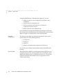
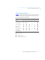
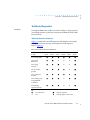
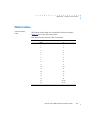
Revision Level History
Revision
Description
A
Initial release.
B
Added new rear panel, ISDN support, new illustrations.
C
Removed ISDN information; ISDN is not supported in RA 4000.
Updated operational image file name (oper.46.enet).
Chapter 3: Added information regarding error codes that reflect
an Ethernet problem during the boot sequence.
Remote Annex 4000 Hardware Installation Guide
iii
Revision Level History
iv
Remote Annex 4000 Hardware Installation Guide
Contents
Preface
About this Guide . . . . . . . . . . . . . . . . . . . . . . . . . . . . . . . . . . . . . . . . . . . . . . . . . . . . . . . . . . . . . . . . . . . . . . . . . . xiii
Printing Conventions . . . . . . . . . . . . . . . . . . . . . . . . . . . . . . . . . . . . . . . . . . . . . . . . . . . . . . . . . . . . . . . . . . . . . . xiv
Related Documents. . . . . . . . . . . . . . . . . . . . . . . . . . . . . . . . . . . . . . . . . . . . . . . . . . . . . . . . . . . . . . . . . . . . . . . . xv
Technical Support and Online Services
Bay Networks Customer Service. . . . . . . . . . . . . . . . . . . . . . . . . . . . . . . . . . . . . . . . . . . . . . . . . . . . . . . . . . . . . xvii
Bay Networks Information Services . . . . . . . . . . . . . . . . . . . . . . . . . . . . . . . . . . . . . . . . . . . . . . . . . . . . . . . . . . . xix
World Wide Web. . . . . . . . . . . . . . . . . . . . . . . . . . . . . . . . . . . . . . . . . . . . . . . . . . . . . . . . . . . . . . . . . . . . . . . xix
Customer Service FTP . . . . . . . . . . . . . . . . . . . . . . . . . . . . . . . . . . . . . . . . . . . . . . . . . . . . . . . . . . . . . . . . . . . xx
Support Source CD. . . . . . . . . . . . . . . . . . . . . . . . . . . . . . . . . . . . . . . . . . . . . . . . . . . . . . . . . . . . . . . . . . . . . xx
CompuServe . . . . . . . . . . . . . . . . . . . . . . . . . . . . . . . . . . . . . . . . . . . . . . . . . . . . . . . . . . . . . . . . . . . . . . . . . . xx
InfoFACTS . . . . . . . . . . . . . . . . . . . . . . . . . . . . . . . . . . . . . . . . . . . . . . . . . . . . . . . . . . . . . . . . . . . . . . . . . . . . . xxi
How to Get Help . . . . . . . . . . . . . . . . . . . . . . . . . . . . . . . . . . . . . . . . . . . . . . . . . . . . . . . . . . . . . . . . . . . . . . .xxii
Chapter 1
Introduction
Remote Network Access . . . . . . . . . . . . . . . . . . . . . . . . . . . . . . . . . . . . . . . . . . . . . . . . . . . . . . . . . . . . . . . . . . . 1-1
Dial-up Routing . . . . . . . . . . . . . . . . . . . . . . . . . . . . . . . . . . . . . . . . . . . . . . . . . . . . . . . . . . . . . . . . . . . . . . . . . . . 1-2
Terminal, Printer, and Communications Access . . . . . . . . . . . . . . . . . . . . . . . . . . . . . . . . . . . . . . . . . . . . . . . . 1-3
Remote Annex 4000 Description . . . . . . . . . . . . . . . . . . . . . . . . . . . . . . . . . . . . . . . . . . . . . . . . . . . . . . . . . . . . 1-4
Main Logic Board . . . . . . . . . . . . . . . . . . . . . . . . . . . . . . . . . . . . . . . . . . . . . . . . . . . . . . . . . . . . . . . . . . . . . . . . . 1-4
Serial Line Controllers . . . . . . . . . . . . . . . . . . . . . . . . . . . . . . . . . . . . . . . . . . . . . . . . . . . . . . . . . . . . . . . . . . . . . . 1-5
Asynchronous SLC . . . . . . . . . . . . . . . . . . . . . . . . . . . . . . . . . . . . . . . . . . . . . . . . . . . . . . . . . . . . . . . . . . . . .1-6
Firmware and Software . . . . . . . . . . . . . . . . . . . . . . . . . . . . . . . . . . . . . . . . . . . . . . . . . . . . . . . . . . . . . . . . . . . . 1-7
Front Panel . . . . . . . . . . . . . . . . . . . . . . . . . . . . . . . . . . . . . . . . . . . . . . . . . . . . . . . . . . . . . . . . . . . . . . . . . . . . . . 1-9
Front Panel Components. . . . . . . . . . . . . . . . . . . . . . . . . . . . . . . . . . . . . . . . . . . . . . . . . . . . . . . . . . . . . . .1-10
Rear Panel. . . . . . . . . . . . . . . . . . . . . . . . . . . . . . . . . . . . . . . . . . . . . . . . . . . . . . . . . . . . . . . . . . . . . . . . . . . . . . 1-11
Rear Panel Components . . . . . . . . . . . . . . . . . . . . . . . . . . . . . . . . . . . . . . . . . . . . . . . . . . . . . . . . . . . . . . .1-12
Physical Characteristics . . . . . . . . . . . . . . . . . . . . . . . . . . . . . . . . . . . . . . . . . . . . . . . . . . . . . . . . . . . . . . . . . . . 1-14
Chapter 2
Installing the Remote Annex 4000
Before you Begin . . . . . . . . . . . . . . . . . . . . . . . . . . . . . . . . . . . . . . . . . . . . . . . . . . . . . . . . . . . . . . . . . . . . . . . . . 2-1
Connecting a LAN Using Ethernet . . . . . . . . . . . . . . . . . . . . . . . . . . . . . . . . . . . . . . . . . . . . . . . . . . . . . . . . . . . 2-2
Connecting Thin Ethernet (10Base2) Cable . . . . . . . . . . . . . . . . . . . . . . . . . . . . . . . . . . . . . . . . . . . . . . . .2-3
Connecting Thick Ethernet (10Base5) Cable . . . . . . . . . . . . . . . . . . . . . . . . . . . . . . . . . . . . . . . . . . . . . . .2-4
Connecting Twisted Pair Ethernet (10BaseT) Cable . . . . . . . . . . . . . . . . . . . . . . . . . . . . . . . . . . . . . . . . . .2-5
Connecting a Console Terminal. . . . . . . . . . . . . . . . . . . . . . . . . . . . . . . . . . . . . . . . . . . . . . . . . . . . . . . . . .2-7
Connecting Serial Devices . . . . . . . . . . . . . . . . . . . . . . . . . . . . . . . . . . . . . . . . . . . . . . . . . . . . . . . . . . . . . .2-9
Connecting a Parallel Printer . . . . . . . . . . . . . . . . . . . . . . . . . . . . . . . . . . . . . . . . . . . . . . . . . . . . . . . . . . .2-14
Powering Up and Testing the Remote Annex 4000 . . . . . . . . . . . . . . . . . . . . . . . . . . . . . . . . . . . . . . . . . . . . 2-15
Installing the Operational Software and Loading the Image. . . . . . . . . . . . . . . . . . . . . . . . . . . . . . . . . . . . 2-19
Installing to and Loading from a Novell Server . . . . . . . . . . . . . . . . . . . . . . . . . . . . . . . . . . . . . . . . . . . . .2-20
Installing to and Loading from a UNIX Host . . . . . . . . . . . . . . . . . . . . . . . . . . . . . . . . . . . . . . . . . . . . . . . .2-22
Installing to and Loading from a VAX VMS Host . . . . . . . . . . . . . . . . . . . . . . . . . . . . . . . . . . . . . . . . . . . .2-23
Auto-initializing the ROMs . . . . . . . . . . . . . . . . . . . . . . . . . . . . . . . . . . . . . . . . . . . . . . . . . . . . . . . . . . . . . . . . . 2-28
BOOTP . . . . . . . . . . . . . . . . . . . . . . . . . . . . . . . . . . . . . . . . . . . . . . . . . . . . . . . . . . . . . . . . . . . . . . . . . . . . . .2-29
RARP . . . . . . . . . . . . . . . . . . . . . . . . . . . . . . . . . . . . . . . . . . . . . . . . . . . . . . . . . . . . . . . . . . . . . . . . . . . . . . . .2-30
Self-booting the Remote Annex 4000 . . . . . . . . . . . . . . . . . . . . . . . . . . . . . . . . . . . . . . . . . . . . . . . . . . . . . . . 2-31
Remote Annex 4000 Hardware Installation Guide
v
Contents
Invoking the Console Monitor . . . . . . . . . . . . . . . . . . . . . . . . . . . . . . . . . . . . . . . . . . . . . . . . . . . . . . . . . . . . . 2-32
Chapter 3
ROM Monitor Commands
Command Descriptions . . . . . . . . . . . . . . . . . . . . . . . . . . . . . . . . . . . . . . . . . . . . . . . . . . . . . . . . . . . . . . . . . . . 3-2
addr . . . . . . . . . . . . . . . . . . . . . . . . . . . . . . . . . . . . . . . . . . . . . . . . . . . . . . . . . . . . . . . . . . . . . . . . . . . . . . . . . 3-5
boot . . . . . . . . . . . . . . . . . . . . . . . . . . . . . . . . . . . . . . . . . . . . . . . . . . . . . . . . . . . . . . . . . . . . . . . . . . . . . . . . . 3-8
config. . . . . . . . . . . . . . . . . . . . . . . . . . . . . . . . . . . . . . . . . . . . . . . . . . . . . . . . . . . . . . . . . . . . . . . . . . . . . . . 3-13
console-baud . . . . . . . . . . . . . . . . . . . . . . . . . . . . . . . . . . . . . . . . . . . . . . . . . . . . . . . . . . . . . . . . . . . . . . . . 3-14
erase . . . . . . . . . . . . . . . . . . . . . . . . . . . . . . . . . . . . . . . . . . . . . . . . . . . . . . . . . . . . . . . . . . . . . . . . . . . . . . . 3-16
help . . . . . . . . . . . . . . . . . . . . . . . . . . . . . . . . . . . . . . . . . . . . . . . . . . . . . . . . . . . . . . . . . . . . . . . . . . . . . . . . 3-17
image . . . . . . . . . . . . . . . . . . . . . . . . . . . . . . . . . . . . . . . . . . . . . . . . . . . . . . . . . . . . . . . . . . . . . . . . . . . . . . 3-18
ipx. . . . . . . . . . . . . . . . . . . . . . . . . . . . . . . . . . . . . . . . . . . . . . . . . . . . . . . . . . . . . . . . . . . . . . . . . . . . . . . . . . 3-19
lat_key . . . . . . . . . . . . . . . . . . . . . . . . . . . . . . . . . . . . . . . . . . . . . . . . . . . . . . . . . . . . . . . . . . . . . . . . . . . . . . 3-20
mop . . . . . . . . . . . . . . . . . . . . . . . . . . . . . . . . . . . . . . . . . . . . . . . . . . . . . . . . . . . . . . . . . . . . . . . . . . . . . . . . 3-21
net . . . . . . . . . . . . . . . . . . . . . . . . . . . . . . . . . . . . . . . . . . . . . . . . . . . . . . . . . . . . . . . . . . . . . . . . . . . . . . . . . 3-22
option_key. . . . . . . . . . . . . . . . . . . . . . . . . . . . . . . . . . . . . . . . . . . . . . . . . . . . . . . . . . . . . . . . . . . . . . . . . . . 3-24
ping . . . . . . . . . . . . . . . . . . . . . . . . . . . . . . . . . . . . . . . . . . . . . . . . . . . . . . . . . . . . . . . . . . . . . . . . . . . . . . . . 3-25
ports . . . . . . . . . . . . . . . . . . . . . . . . . . . . . . . . . . . . . . . . . . . . . . . . . . . . . . . . . . . . . . . . . . . . . . . . . . . . . . . . 3-26
sequence . . . . . . . . . . . . . . . . . . . . . . . . . . . . . . . . . . . . . . . . . . . . . . . . . . . . . . . . . . . . . . . . . . . . . . . . . . . 3-29
slip . . . . . . . . . . . . . . . . . . . . . . . . . . . . . . . . . . . . . . . . . . . . . . . . . . . . . . . . . . . . . . . . . . . . . . . . . . . . . . . . . 3-31
stats . . . . . . . . . . . . . . . . . . . . . . . . . . . . . . . . . . . . . . . . . . . . . . . . . . . . . . . . . . . . . . . . . . . . . . . . . . . . . . . . 3-33
Chapter 4
Troubleshooting Procedures
Power-up and Boot Procedures. . . . . . . . . . . . . . . . . . . . . . . . . . . . . . . . . . . . . . . . . . . . . . . . . . . . . . . . . . . . . 4-2
Normal Mode Diagnostics. . . . . . . . . . . . . . . . . . . . . . . . . . . . . . . . . . . . . . . . . . . . . . . . . . . . . . . . . . . . . . . 4-2
Test Mode Diagnostics. . . . . . . . . . . . . . . . . . . . . . . . . . . . . . . . . . . . . . . . . . . . . . . . . . . . . . . . . . . . . . . . . . 4-7
Boot Failures . . . . . . . . . . . . . . . . . . . . . . . . . . . . . . . . . . . . . . . . . . . . . . . . . . . . . . . . . . . . . . . . . . . . . . . . . . . . 4-11
Boot Error Report . . . . . . . . . . . . . . . . . . . . . . . . . . . . . . . . . . . . . . . . . . . . . . . . . . . . . . . . . . . . . . . . . . . . . 4-12
Correcting Remote Annex 4000 Parameters . . . . . . . . . . . . . . . . . . . . . . . . . . . . . . . . . . . . . . . . . . . . . . 4-14
Load Server Host Not Responding . . . . . . . . . . . . . . . . . . . . . . . . . . . . . . . . . . . . . . . . . . . . . . . . . . . . . . . 4-16
Remote Annex 4000 Dumps . . . . . . . . . . . . . . . . . . . . . . . . . . . . . . . . . . . . . . . . . . . . . . . . . . . . . . . . . . . . . . 4-20
Appendix A
Port Pins and Signals
Console Port . . . . . . . . . . . . . . . . . . . . . . . . . . . . . . . . . . . . . . . . . . . . . . . . . . . . . . . . . . . . . . . . . . . . . . . . . . . . .
10Base2 Ethernet Port . . . . . . . . . . . . . . . . . . . . . . . . . . . . . . . . . . . . . . . . . . . . . . . . . . . . . . . . . . . . . . . . . . . . .
10Base5 Ethernet Port . . . . . . . . . . . . . . . . . . . . . . . . . . . . . . . . . . . . . . . . . . . . . . . . . . . . . . . . . . . . . . . . . . . . .
10BaseT Ethernet Port . . . . . . . . . . . . . . . . . . . . . . . . . . . . . . . . . . . . . . . . . . . . . . . . . . . . . . . . . . . . . . . . . . . . .
Serial Port . . . . . . . . . . . . . . . . . . . . . . . . . . . . . . . . . . . . . . . . . . . . . . . . . . . . . . . . . . . . . . . . . . . . . . . . . . . . . . .
Parallel Printer Port . . . . . . . . . . . . . . . . . . . . . . . . . . . . . . . . . . . . . . . . . . . . . . . . . . . . . . . . . . . . . . . . . . . . . . . .
Appendix B
A-1
A-2
A-3
A-4
A-5
A-7
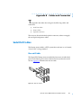
Cables and Connectors
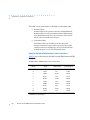
Serial Port Cables . . . . . . . . . . . . . . . . . . . . . . . . . . . . . . . . . . . . . . . . . . . . . . . . . . . . . . . . . . . . . . . . . . . . . . . . . B-1
Fan-out Cable . . . . . . . . . . . . . . . . . . . . . . . . . . . . . . . . . . . . . . . . . . . . . . . . . . . . . . . . . . . . . . . . . . . . . . . .B-1
Printer Cables . . . . . . . . . . . . . . . . . . . . . . . . . . . . . . . . . . . . . . . . . . . . . . . . . . . . . . . . . . . . . . . . . . . . . . . . . . . . B-9
Loopback Connectors . . . . . . . . . . . . . . . . . . . . . . . . . . . . . . . . . . . . . . . . . . . . . . . . . . . . . . . . . . . . . . . . . . . B-11
Appendix C
Port Upgrade Instructions
Contents of the Kit . . . . . . . . . . . . . . . . . . . . . . . . . . . . . . . . . . . . . . . . . . . . . . . . . . . . . . . . . . . . . . . . . . . . . . . . C-1
Required Tools. . . . . . . . . . . . . . . . . . . . . . . . . . . . . . . . . . . . . . . . . . . . . . . . . . . . . . . . . . . . . . . . . . . . . . . . C-1
vi
Remote Annex 4000 Hardware Installation Guide
Contents
Disassembly Instructions. . . . . . . . . . . . . . . . . . . . . . . . . . . . . . . . . . . . . . . . . . . . . . . . . . . . . . . . . . . . . . . . . . . .
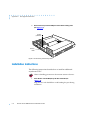
Installation Instructions . . . . . . . . . . . . . . . . . . . . . . . . . . . . . . . . . . . . . . . . . . . . . . . . . . . . . . . . . . . . . . . . . . . . .
Assembly Instructions . . . . . . . . . . . . . . . . . . . . . . . . . . . . . . . . . . . . . . . . . . . . . . . . . . . . . . . . . . . . . . . . . . . . . .
Power-up and Test . . . . . . . . . . . . . . . . . . . . . . . . . . . . . . . . . . . . . . . . . . . . . . . . . . . . . . . . . . . . . . . . . . . . . . . .
Remote Annex 4000 Hardware Installation Guide
C-2
C-4
C-7
C-8
vii
Contents
viii
Remote Annex 4000 Hardware Installation Guide
Figures
Figure 1-1. The Remote Annex 4000 as a Remote Access Server . . . . . . . . . . . . . . . . . . . . . . . . . . . . . . . . . . 1-1
Figure 1-2. The Remote Annex 4000 as a Dial-up Router . . . . . . . . . . . . . . . . . . . . . . . . . . . . . . . . . . . . . . . . . 1-2
Figure 1-3. Remote Annex 4000 as a Terminal, Printer, and Communications Server. . . . . . . . . . . . . . . . . . 1-3
Figure 1-4. Remote Annex 4000 Series . . . . . . . . . . . . . . . . . . . . . . . . . . . . . . . . . . . . . . . . . . . . . . . . . . . . . . . . 1-4
Figure 1-5. Remote Annex 4000 with Two Asynchronous SLCs. . . . . . . . . . . . . . . . . . . . . . . . . . . . . . . . . . . . . 1-6
Figure 1-6. Remote Annex 4000 Front Panel . . . . . . . . . . . . . . . . . . . . . . . . . . . . . . . . . . . . . . . . . . . . . . . . . . . 1-9
Figure 1-7. Remote Annex 4000 Rear Panel. . . . . . . . . . . . . . . . . . . . . . . . . . . . . . . . . . . . . . . . . . . . . . . . . . . 1-12
Figure 2-1. Remote Annex 4000 Ethernet Connections . . . . . . . . . . . . . . . . . . . . . . . . . . . . . . . . . . . . . . . . . . 2-2
Figure 2-2. Connecting Thin Ethernet Cable . . . . . . . . . . . . . . . . . . . . . . . . . . . . . . . . . . . . . . . . . . . . . . . . . . . 2-4
Figure 2-3. Connecting Thick Ethernet Cable . . . . . . . . . . . . . . . . . . . . . . . . . . . . . . . . . . . . . . . . . . . . . . . . . . 2-5
Figure 2-4. Connecting Twisted Pair Ethernet Cable . . . . . . . . . . . . . . . . . . . . . . . . . . . . . . . . . . . . . . . . . . . . 2-6
Figure 2-5. Connecting the RJ-45 Cable to the DB-25 DTE Drop Adapter . . . . . . . . . . . . . . . . . . . . . . . . . . . 2-7
Figure 2-6. Connecting to a Console Terminal . . . . . . . . . . . . . . . . . . . . . . . . . . . . . . . . . . . . . . . . . . . . . . . . . 2-8
Figure 2-7. Removing the Remote Annex 4000 Dress Panel Cover . . . . . . . . . . . . . . . . . . . . . . . . . . . . . . . . . 2-9
Figure 2-8. Moving the Cable Retainer to Make Room for the Cable . . . . . . . . . . . . . . . . . . . . . . . . . . . . . 2-10
Figure 2-9. Attaching the Cable to the PBX Connector . . . . . . . . . . . . . . . . . . . . . . . . . . . . . . . . . . . . . . . . 2-10
Figure 2-10. Securing the PBX Cable . . . . . . . . . . . . . . . . . . . . . . . . . . . . . . . . . . . . . . . . . . . . . . . . . . . . . . . . 2-11
Figure 2-11. Securing the PBX Connector . . . . . . . . . . . . . . . . . . . . . . . . . . . . . . . . . . . . . . . . . . . . . . . . . . . . 2-11
Figure 2-12. Securing the Dress Panel Cover . . . . . . . . . . . . . . . . . . . . . . . . . . . . . . . . . . . . . . . . . . . . . . . . . . 2-12
Figure 2-13. Connecting the Parallel Printer Cable to the Remote Annex 4000 . . . . . . . . . . . . . . . . . . . . . 2-14
Figure 2-15. Connecting the Power Cord . . . . . . . . . . . . . . . . . . . . . . . . . . . . . . . . . . . . . . . . . . . . . . . . . . . . 2-16
Figure 2-16. Setting the Remote Annex 4000 to Test Mode . . . . . . . . . . . . . . . . . . . . . . . . . . . . . . . . . . . . . . 2-17
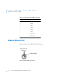
Figure A-1. RJ45 Console Port . . . . . . . . . . . . . . . . . . . . . . . . . . . . . . . . . . . . . . . . . . . . . . . . . . . . . . . . . . . . . . A-1
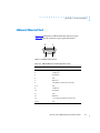
Figure A-2. 10Base2 BNC Ethernet Port . . . . . . . . . . . . . . . . . . . . . . . . . . . . . . . . . . . . . . . . . . . . . . . . . . . . . . A-2
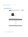
Figure A-3. 10Base5 Ethernet Port . . . . . . . . . . . . . . . . . . . . . . . . . . . . . . . . . . . . . . . . . . . . . . . . . . . . . . . . . . . A-3
Figure A-4. 10BaseT RJ45 Ethernet Port. . . . . . . . . . . . . . . . . . . . . . . . . . . . . . . . . . . . . . . . . . . . . . . . . . . . . . . A-4
Figure A-5. Serial Port Receptacle . . . . . . . . . . . . . . . . . . . . . . . . . . . . . . . . . . . . . . . . . . . . . . . . . . . . . . . . . . A-5
Figure A-6. Parallel Printer Port. . . . . . . . . . . . . . . . . . . . . . . . . . . . . . . . . . . . . . . . . . . . . . . . . . . . . . . . . . . . . . A-7
Figure B-1. Fan-out Cable . . . . . . . . . . . . . . . . . . . . . . . . . . . . . . . . . . . . . . . . . . . . . . . . . . . . . . . . . . . . . . . . . .B-1
Figure B-2. DTE Crossover Terminal Cable . . . . . . . . . . . . . . . . . . . . . . . . . . . . . . . . . . . . . . . . . . . . . . . . . . . . .B-7
Figure B-3. DCE Straight-Through Modem Cable . . . . . . . . . . . . . . . . . . . . . . . . . . . . . . . . . . . . . . . . . . . . . . . B-8
Figure B-4. RJ45 Console to DTE Terminal . . . . . . . . . . . . . . . . . . . . . . . . . . . . . . . . . . . . . . . . . . . . . . . . . . . . . .B-8
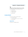
Figure C-1. Removing the Dress Panel Cover . . . . . . . . . . . . . . . . . . . . . . . . . . . . . . . . . . . . . . . . . . . . . . . . . C-2
Figure C-2. Removing the Screws from the Cover . . . . . . . . . . . . . . . . . . . . . . . . . . . . . . . . . . . . . . . . . . . . . C-3
Figure C-3. Removing the Cover. . . . . . . . . . . . . . . . . . . . . . . . . . . . . . . . . . . . . . . . . . . . . . . . . . . . . . . . . . . . C-3
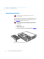
Figure C-4. Removing the Dummy Plate . . . . . . . . . . . . . . . . . . . . . . . . . . . . . . . . . . . . . . . . . . . . . . . . . . . . . C-4
Figure C-5. Lowering the SLC onto the MLB. . . . . . . . . . . . . . . . . . . . . . . . . . . . . . . . . . . . . . . . . . . . . . . . . . . C-5
Figure C-6. Attaching the SLC Connectors . . . . . . . . . . . . . . . . . . . . . . . . . . . . . . . . . . . . . . . . . . . . . . . . . . . C-5
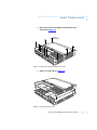
Figure C-7. Securing the SLC to the Rear Panel . . . . . . . . . . . . . . . . . . . . . . . . . . . . . . . . . . . . . . . . . . . . . . . C-6
Figure C-8. Securing the SLC to the MLB . . . . . . . . . . . . . . . . . . . . . . . . . . . . . . . . . . . . . . . . . . . . . . . . . . . . . C-6
Figure C-9. Replacing the Remote Annex 4000’s Cover . . . . . . . . . . . . . . . . . . . . . . . . . . . . . . . . . . . . . . . . C-7
Figure C-10. Securing the Cover . . . . . . . . . . . . . . . . . . . . . . . . . . . . . . . . . . . . . . . . . . . . . . . . . . . . . . . . . . . . C-8
Figure C-11. Setting the Remote Annex 4000 to Test Mode . . . . . . . . . . . . . . . . . . . . . . . . . . . . . . . . . . . . . C-9
Figure C-12. Attaching a PBX Loopback Plug to the PBX Connectors. . . . . . . . . . . . . . . . . . . . . . . . . . . . C-10
Remote Annex 4000 Hardware Installation Guide
ix
Figures
x
Remote Annex 4000 Hardware Installation Guide
Tables
Table 1-1. Remote Annex 4000 Configurations . . . . . . . . . . . . . . . . . . . . . . . . . . . . . . . . . . . . . . . . . . . . . . .
Table 1-2. Front Panel System LEDs . . . . . . . . . . . . . . . . . . . . . . . . . . . . . . . . . . . . . . . . . . . . . . . . . . . . . . . .
Table 2-1. Remote Annex 4000 Configuration Options . . . . . . . . . . . . . . . . . . . . . . . . . . . . . . . . . . . . . . . .
Table 2-2. Recommended Cable Lengths . . . . . . . . . . . . . . . . . . . . . . . . . . . . . . . . . . . . . . . . . . . . . . . . .
Table 3-1. ROM Monitor Commands . . . . . . . . . . . . . . . . . . . . . . . . . . . . . . . . . . . . . . . . . . . . . . . . . . . . . . .
Table 3-2. The slip Command Prompts . . . . . . . . . . . . . . . . . . . . . . . . . . . . . . . . . . . . . . . . . . . . . . . . . . . . .
Table 3-3. Network Statistics. . . . . . . . . . . . . . . . . . . . . . . . . . . . . . . . . . . . . . . . . . . . . . . . . . . . . . . . . . . . . .
Table 4-1. Normal Mode Error-free LED States . . . . . . . . . . . . . . . . . . . . . . . . . . . . . . . . . . . . . . . . . . . . . . . .
Table 4-2. Normal Mode Error LED States . . . . . . . . . . . . . . . . . . . . . . . . . . . . . . . . . . . . . . . . . . . . . . . . . . . .
Table 4-3. Test Mode Error-free LED States . . . . . . . . . . . . . . . . . . . . . . . . . . . . . . . . . . . . . . . . . . . . . . . . . . .
Table 4-4. Test Mode Error LED States . . . . . . . . . . . . . . . . . . . . . . . . . . . . . . . . . . . . . . . . . . . . . . . . . . . . . . .
Table 4-5. Errors from Last ERPC Layer Invocation . . . . . . . . . . . . . . . . . . . . . . . . . . . . . . . . . . . . . . . . . . . .
Table 4-6. Errors from Last Read Request . . . . . . . . . . . . . . . . . . . . . . . . . . . . . . . . . . . . . . . . . . . . . . . . . . .
Table 4-7. Errors from Last Open Request. . . . . . . . . . . . . . . . . . . . . . . . . . . . . . . . . . . . . . . . . . . . . . . . . . .
Table 4-8. LED States During a Dump . . . . . . . . . . . . . . . . . . . . . . . . . . . . . . . . . . . . . . . . . . . . . . . . . . . . . .
Table 4-9. Dump File Naming Conventions . . . . . . . . . . . . . . . . . . . . . . . . . . . . . . . . . . . . . . . . . . . . . . . . .
Table A-1. RJ45 Console Port Pin/Signal Allocations . . . . . . . . . . . . . . . . . . . . . . . . . . . . . . . . . . . . . . . . . . .
Table A-2. 10Base5 Ethernet Port Pin/Signal Allocation . . . . . . . . . . . . . . . . . . . . . . . . . . . . . . . . . . . . . . . .
Table A-3. 10BaseT Ethernet Port Pin/Signal Allocations. . . . . . . . . . . . . . . . . . . . . . . . . . . . . . . . . . . . . . . .
Table A-4. Serial Port Pin/Signal Allocations . . . . . . . . . . . . . . . . . . . . . . . . . . . . . . . . . . . . . . . . . . . . . . . . . .
Table A-5. Parallel Printer Port Pin/Signal Allocations . . . . . . . . . . . . . . . . . . . . . . . . . . . . . . . . . . . . . . . . . .
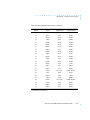
Table B-1. PBX to DB25 Terminal Cable Connections . . . . . . . . . . . . . . . . . . . . . . . . . . . . . . . . . . . . . . . . . .
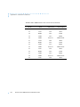
Table B-2. PBX to DB25 Modem Cable Connections . . . . . . . . . . . . . . . . . . . . . . . . . . . . . . . . . . . . . . . . . .
Table B-3. Centronics Printer Cable Connections. . . . . . . . . . . . . . . . . . . . . . . . . . . . . . . . . . . . . . . . . . . . .
Table B-4. Dataproducts Printer Cable Connections . . . . . . . . . . . . . . . . . . . . . . . . . . . . . . . . . . . . . . . . .
Table B-5. 10Base5 Ethernet Loopback Connector . . . . . . . . . . . . . . . . . . . . . . . . . . . . . . . . . . . . . . . . . .
Table B-6. 10BaseT Ethernet Loopback Connector Wiring. . . . . . . . . . . . . . . . . . . . . . . . . . . . . . . . . . . . .
Table B-7. PBX Loopback Connector Wiring . . . . . . . . . . . . . . . . . . . . . . . . . . . . . . . . . . . . . . . . . . . . . . . .
Remote Annex 4000 Hardware Installation Guide
1-5
1-10
2-1
2-13
3-2
3-32
3-33
4-3
4-5
4-7
4-9
4-13
4-13
4-14
4-20
4-22
A-2
A-3
A-4
A-6
A-8
B-2
B-5
B-9
B-10
B-11
B-11
B-12
xi
Tables
xii
Remote Annex 4000 Hardware Installation Guide
Preface
T
his guide describes how to install a Remote Annex 4000 Series on
a local area network (LAN).
See the software installation notes that come with your Remote Annex
4000 for a description of the software installation. See the Remote
Annex Administrator’s Guide for UNIX for configuration information.
About this Guide
This guide includes the following chapters and appendices:
Chapter 1
Introduction
This chapter contains an overview of the Remote
Annex 4000; it describes the hardware features and
firmware functions.
Chapter 2
Installing the Remote Annex 4000
This chapter contains a description of how to install
the Remote Annex 4000 on a LAN, and how to
confirm its operating status.
Chapter 3
ROM Monitor Commands
This chapter contains a description of the ROM
Monitor commands that modify specific
configuration parameters, perform diagnostic tests,
and load the operational code.
Chapter 4
Troubleshooting Procedures
This chapter provides troubleshooting and
verification procedures.
Remote Annex 4000 Hardware Installation Guide
xiii
Preface
Appendix A
Port Pins and Signals
This appendix details the connectors located on the
rear panel of the Remote Annex 4000.
Appendix B
Cables and Connectors
This appendix contains a description of the wiring
for Remote Annex 4000 cables.
Appendix C
Port Upgrade Instructions
This appendix contains port upgrade instructions.
Appendix D
Warranty and Technical Support Information
This appendix contains warranty and technical
support information.
Printing Conventions
This manual uses the following printing conventions:
Convention:
Represents:
special type
In examples, special type indicates system output.
special type
Bold special type indicates user input.
Return
xiv
In command examples, this notation indicates that
pressing Return enters the default value.
bold
Bold indicates commands, pathnames, or filenames
that must be entered as displayed.
italics
In the context of commands and command syntax,
lowercase italics indicate variables for which the user
supplies a value.
Remote Annex 4000 Hardware Installation Guide
Preface
Convention:
Represents:
[]
In command dialogue, square brackets indicate default
values. Pressing Return selects this value. Square
brackets appearing in command syntax indicate
optional arguments.
{}
In command syntax, braces indicate that one, and only
one, of the enclosed value must be entered.
|
In command syntax, this character separates the
different options available for a parameter.
Notes give you important information.
Warnings inform you about conditions that can have
adverse effects on processing.
Cautions notify you about dangerous conditions.
Related Documents
Each Remote Annex hardware platform ships with the appropriate
hardware guide. The remaining documentation is included with the
software.
Remote Annex 4000 Hardware Installation Guide
xv
Preface
xvi
Remote Annex 4000 Hardware Installation Guide
Technical Support and Online Services
T
o ensure comprehensive network support to our customers and
partners worldwide, Bay Networks Customer Service has
Technical Response Centers in key locations around the globe:
❑
Billerica, Massachusetts
❑
Santa Clara, California
❑
Sydney, Australia
❑
Tokyo, Japan
❑
Valbonne, France
The Technical Response Centers are connected via a redundant
Frame Relay Network to a Common Problem Resolution system,
enabling them to transmit and share information, and to provide
live, around-the-clock support 365 days a year.
Bay Networks Information Services complement the Bay Networks
Service program portfolio by giving customers and partners access
to the most current technical and support information through a
choice of access/retrieval means. These include the World Wide
Web, CompuServe, Support Source CD, Customer Support FTP,
and InfoFACTS document fax service.
Bay Networks Customer Service
If you purchased your Bay Networks product from a distributor or
authorized reseller, contact that distributor’s or reseller’s technical
support staff for assistance with installation, configuration,
troubleshooting, or integration issues.
Remote Annex 4000 Hardware Installation Guide
xvii
Technical Support and Online Services
Customers can also purchase direct support from Bay Networks
through a variety of service programs. As part of our PhonePlus™
program, Bay Networks Service sets the industry standard, with
24-hour, 7-days-a-week telephone support available worldwide at
no extra cost. Our complete range of contract and noncontract
services also includes equipment staging and integration,
installation support, on-site services, and replacement parts
delivery -- within approximately 4 hours.
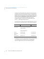
To purchase any of the Bay Networks support programs, or if you
have questions on program features, use the following numbers:
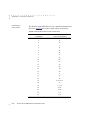
Region
Telephone Number
Fax Number
United States
and Canada
1-800-2LANWAN; enter
Express Routing Code (ERC) 290
when prompted
(508) 670-8766
(508) 436-8880 (direct)
Europe
(33) 92-968-300
(33) 92-968-301
Asia/Pacific
Region
(612) 9927-8800
(612) 9927-8811
Latin America
(407) 997-1713
(407) 997-1714
In addition, you can receive information on support programs from
your local Bay Networks field sales office, or purchase Bay
Networks support directly from your authorized partner.
xviii
Remote Annex 4000 Hardware Installation Guide
Technical Support and Online Services
Bay Networks Information Services
Bay Networks Information Services provide up-to-date support
information as a first-line resource for network administration,
expansion, and maintenance. This information is available from a
variety of sources.
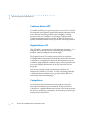
World Wide Web
The Bay Networks Customer Support Web Server offers a diverse
library of technical documents, software agents, and other
important technical information to Bay Networks customers and
partners.
A special benefit for contracted customers and resellers is the ability
to access the Web Server to perform Case Management. This feature
enables your support staff to interact directly with the network
experts in our worldwide Technical Response Centers. A registered
contact with a valid Site ID can:
❑
View a listing of support cases and determine the current
status of any open case. Case history data includes severity
designation, and telephone, e-mail, or other logs
associated with the case.
❑
Customize the listing of cases according to a variety of
criteria, including date, severity, status, and case ID.
❑
Log notes to existing open cases.
❑
Create new cases for rapid, efficient handling of
noncritical network situations.
❑
Communicate directly via e-mail with the specific
technical resources assigned to your case.
The Bay Networks URL is http://www.baynetworks.com. Customer
Service is a menu item on that home page.
Remote Annex 4000 Hardware Installation Guide
xix
Technical Support and Online Services
Customer Service FTP
Accessible via URL ftp://support.baynetworks.com (134.177.3.26), this
site combines and organizes support files and documentation from
across the Bay Networks product suite, including switching
products from our Centillion™ and Xylogics® business units.
Central management and sponsorship of this FTP site lets you
quickly locate information on any of your Bay Networks products.
Support Source CD
This CD-ROM -- sent quarterly to all contracted customers -- is a
complete Bay Networks Service troubleshooting knowledge
database with an intelligent text search engine.
The Support Source CD contains extracts from our problemtracking database; information from the Bay Networks Forum on
CompuServe; comprehensive technical documentation, such as
Customer Support Bulletins, Release Notes, software patches and
fixes; and complete information on all Bay Networks Service
programs.
You can run a single version on Macintosh, Windows 3.1,
Windows 95, Windows NT, DOS, or UNIX computing platforms.
A Web links feature enables you to go directly from the CD to
various Bay Networks Web pages.
CompuServe
For assistance with noncritical network support issues, Bay
Networks Information Services maintain an active forum on
CompuServe, a global bulletin-board system. This forum provides
file services, technology conferences, and a message section to get
assistance from other users.
xx
Remote Annex 4000 Hardware Installation Guide
Technical Support and Online Services
The message section is monitored by Bay Networks engineers, who
provide assistance wherever possible. Customers and resellers
holding Bay Networks service contracts also have access to special
libraries for advanced levels of support documentation and
software. To take advantage of CompuServe’s recently enhanced
menu options, the Bay Networks Forum has been re-engineered to
allow links to our Web sites and FTP sites.
We recommend the use of CompuServe Information Manager
software to access these Bay Networks Information Services
resources. To open an account and receive a local dial-up number
in the United States, call CompuServe at 1-800-524-3388. Outside
the United States, call 1-614-529-1349, or your nearest CompuServe
office. Ask for Representative No. 591. When you are on line with
your CompuServe account, you can reach us with the command
GO BAYNET.
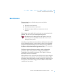
InfoFACTS
InfoFACTS is the Bay Networks free 24-hour fax-on-demand
service. This automated system has libraries of technical and
product documents designed to help you manage and troubleshoot
your Bay Networks products. The system responds to a fax from
the caller or to a third party within minutes of being accessed.
To use InfoFACTS in the United States or Canada, call toll-free 1800-786-3228. Outside North America, toll calls can be made to 1408-764-1002. In Europe, toll-free numbers are also available for
contacting both InfoFACTS and CompuServe. Please check our
Web page for the listing in your country.
Remote Annex 4000 Hardware Installation Guide
xxi
Technical Support and Online Services
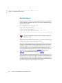
How to Get Help
Use the following numbers to reach your Bay Networks Technical
Response Center:
xxii
Technical Response
Center
Telephone Number
Fax Number
Billerica, MA
1-800-2LANWAN
(508) 670-8765
Santa Clara, CA
1-800-2LANWAN
(408) 764-1188
Valbonne, France
(33) 92-968-968
(33) 92-966-998
Sydney, Australia
(612) 9927-8800
(612) 9927-8811
Tokyo, Japan
(81) 3-5402-0180
(81) 3-5402-0173
Remote Annex 4000 Hardware Installation Guide
Chapter 1
Introduction
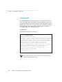
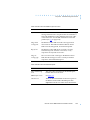
T
he Remote Annex 4000 is a multi-purpose network server. The
Remote Annex 4000 is used for:
❑
Remote Network Access.
❑
Dial-up Routing.
❑
Terminal, Printer, and Communications Access.
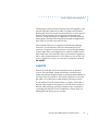
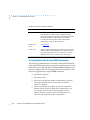
Remote Network Access
The Remote Annex 4000 is a multi-protocol, remote access server that
provides remote network access to the following networks:
❑
Novell Netware.
❑
TCP/IP.
❑
AppleTalk.
Figure 1-1 shows how the Remote Annex 4000 is used for remote
access.
DEC
IBM
UNIX
Corporate LAN
Ethernet
Remote
Annex 4000
Novell
Server
Apple
Macintosh
Dial-In
Connection
Figure 1-1. The Remote Annex 4000 as a Remote Access Server
Remote Annex 4000 Hardware Installation Guide
1-1
Chapter 1
Introduction
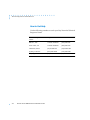
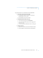
Dial-up Routing
The Remote Annex 4000 provides dial-up routing support for UNIX
and Novell networks. Using a Remote Annex 4000, network
administrators can connect two or more local area networks (LANs)
over a wide area network (WAN) using a standard telephone line.
Figure 1-2 shows how the Remote Annex 4000 is used for dial-up
routing.
DEC
IBM
UNIX
Corporate LAN
Ethernet
Remote
Annex 4000
Novell
Server
Workstation
Wide Area Network
Remote LAN
PC Using
TCP/IP
Ethernet
Remote
Annex 4000
Figure 1-2. The Remote Annex 4000 as a Dial-up Router
1-2
Remote Annex 4000 Hardware Installation Guide
Chapter 1
Introduction
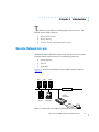
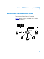
Terminal, Printer, and Communications Access
The Remote Annex 4000 provides terminal, printer, and
communications access to users on a local area network.
Figure 1-3 shows how the Remote Annex 4000 is used as a terminal
and communications server.
DEC
IBM
UNIX
Corporate LAN
Ethernet
Remote
Annex 4000
Remote
Terminal
Personal
Computer
Terminal
Plotter
Laser
Printer
Figure 1-3. Remote Annex 4000 as a Terminal, Printer, and Communications Server
Remote Annex 4000 Hardware Installation Guide
1-3
Chapter 1
Introduction
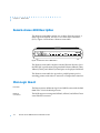
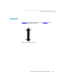
Remote Annex 4000 Description
The Remote Annex 4000 contains two or three 32-bit processors, a
main logic board (MLB), and one or two Serial Line Controllers
(SLCs). Figure 1-4 illustrates a Remote Annex 4000.
STATUS
POWER
UNIT
NET
ATTN
LOAD
ACTIVE
1
2
3
4
5
6
7
8
TEST
Figure 1-4. Remote Annex 4000 Series
The Remote Annex 4000 complies with the Ethernet Revision 2.0 or
the IEEE 802.3 specifications using standard Ethernet 10Base2 (Thin),
10Base5 (Thick), and 10BaseT (twisted pair) as the physical medium.
The Remote Annex 4000 also provides a parallel printer port for
attaching printers with either a Centronics or Dataproducts interface.
Main Logic Board
Processor
The Remote Annex 4000 main logic board (MLB) comes with the Intel
80486 SXLC2 clock-doubled processor.
Ethernet
Connector
The MLB supports an integrated 10Base2, 10Base5, and 10BaseT auto
sense Ethernet connector.
1-4
Remote Annex 4000 Hardware Installation Guide
Chapter 1
Memory
Introduction
The MLB can be configured with 1 to 8 megabytes of on-board
memory. One megabyte is permanent with two slots for either 1- or
4-megabyte SIMMs. The Remote Annex 4000 supports a total of 8
megabytes of memory.
By default, the Remote Annex 4000 comes with 3 megabytes
of memory on the MLB and 1.5 megabytes of memory on
the SLC.
Flash Memory
The MLB supports 2 megabytes of optional flash memory.
Serial Line Controllers
The Remote Annex 4000 can have either one or two SLCs that support
asynchronous communications. Using both SLCs, the Remote Annex
4000 can support up to 72 ports.
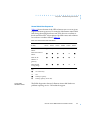
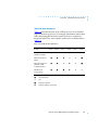
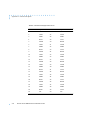
Table 1-1 illustrates the available Remote Annex 4000 configurations
including the SLC, PBX connectors, and ports associated with each
configuration.
Table 1-1. Remote Annex 4000 Configurations
SLC Type
Number of PBX
Connectors
Number of
Ports
Port
Count
Port
Numbers
Asynchronous
3 or 6 asynch
18 or 36
18 or 36
1-18 or 36
The Remote Annex 4000 connects from 1 to 72 devices to host
computers on a local area network (LAN) through its serial line
controllers (SLCs). Each SLC comes with an intel 80486 SLC processor
and 1.5 megabytes of memory.
Remote Annex 4000 Hardware Installation Guide
1-5
Chapter 1
Introduction
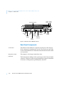
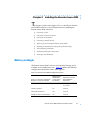
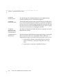
Asynchronous SLC
The Remote Annex 4000 can be purchased with asynchronous SLCs.
The SLC types available are:
❑
18-port SLC
❑
36-port SLC
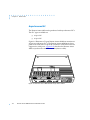
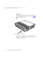
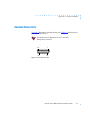
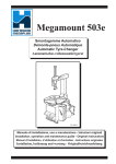
Figure 1-6 illustrates a 72-port Remote Annex 4000 that contains two
36-port asynchronous SLCs. The Remote Annex 4000 has its dress
panel cover removed to expose the connectors. Each PBX connector
supports six serial ports. Appendix B describes the Remote Annex
4000’s asynchronous serial device cable (fan-out cable).
Figure 1-5. Remote Annex 4000 with Two Asynchronous SLCs
1-6
Remote Annex 4000 Hardware Installation Guide
Chapter 1
Introduction
Asynchronous Ports
Each asynchronous port has seven active pins, plus ground, to
provide the following standard RS232 asynchronous signals for
modem and flow control:
❑
Transmit Data (TxD, transmitted).
❑
Receive Data (RxD, received).
❑
Data Terminal Ready (DTR, transmitted).
❑
Clear To Send (CTS, received).
❑
Data Set Ready (DSR, received).
❑
Request to Send (RTS, transmitted).
❑
Carrier Detect (DCD, received).
Firmware and Software
Firmware
The Remote Annex 4000’s ROM contains firmware for performing
power-up self-tests and loading operational code. A non-volatile
EEPROM stores the configuration parameters.
The Remote Annex 4000 can have a boot image in Flash ROM
(optional) or can receive its image from a device on the network. This
image is used to boot the Remote Annex 4000.
ROM Monitor
When the Remote Annex 4000 is first booted, the console displays the
ROM monitor prompt. The ROM monitor is an interactive command
interpreter that is used to define configuration parameters. All of the
information that the Remote Annex 4000 needs to boot an operational
image is defined using the ROM monitor and its command set. ROM
Monitor commands are issued from a console terminal connected to
the console port on the Remote Annex 4000’s rear panel.
Remote Annex 4000 Hardware Installation Guide
1-7
Chapter 1
Introduction
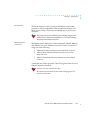
Using the ROM Monitor commands (see Chapter 3), you can:
❑
Modify and display a set of configuration parameters stored
in EEPROM.
❑
Execute interactive diagnostic tests.
❑
Receive information and statistics for the hardware
configuration and the network.
❑
Boot the Remote Annex 4000 manually.
Once the Remote Annex 4000 has obtained a boot image and is booted,
the console leaves the ROM monitor and displays the console monitor.
Refer to Chapter 2 for information on the console monitor.
Supported
Configurations
The Remote Annex 4000 can obtain full operational code over the
network from one of the following devices:
❑
Novell server.
❑
UNIX host.
❑
VMS host.
❑
Remote Annex 4000 Series configured as a load server.
You can also boot a Remote Annex 4000 from the Flash ROM (selfbooting).
Watchdog Timer
1-8
The Remote Annex 4000 has a watchdog timer that its software resets
at regular intervals. The watchdog timer reboots the Remote Annex
4000 in the unlikely event of an internal software error. This feature
enables the Remote Annex 4000 to run for long periods of time
without intervention.
Remote Annex 4000 Hardware Installation Guide
Chapter 1
Introduction
Front Panel
The Remote Annex 4000’s front panel consists of:
❑
Six system LEDs.
❑
One test LED.
❑
One test button.
❑
Eight status LEDs.
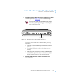
Figure 1-6 illustrates the Remote Annex 4000’s front panel.
Table 1-2 describes the panel’s system LEDs.
STATUS
POWER
UNIT
NET
ATTN
LOAD
ACTIVE
1
2
3
4
5
6
7
8
TEST
System
LEDs
Test
LED
Test
Button
Status
LEDs
Figure 1-6. Remote Annex 4000 Front Panel
Remote Annex 4000 Hardware Installation Guide
1-9
Chapter 1
Introduction
Front Panel Components
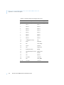
System LEDs
There are six System LEDs on the front of the Remote Annex 4000.
The LEDs turn on or off to describe the Remote Annex 4000’s state.
Table 1-2 describes the LEDs.
Table 1-2. Front Panel System LEDs
Test LED
1-10
LED
Definition
POWER
On when the unit is receiving AC power and the internal DC
power supply is working properly.
UNIT
On after the unit successfully passes its self-test.
NET
On when the unit successfully transmits test data to, and
receives test data from, the network.
ATTN
On when the unit requires operator attention; flashing when
the unit encounters a problem.
LOAD
On when the unit is loading or dumping; flashing when the
unit is trying to initiate a load.
ACTIVE
Flashing when the unit is transmitting data to, and receiving
data from the network; flashing during diagnostics.
The Test LED is on the front of the Remote Annex 4000 and lights
when the Remote Annex 4000 is in test mode.
Remote Annex 4000 Hardware Installation Guide
Chapter 1
Test Button
Introduction
The Test Button allows you to change the operational mode of the
Remote Annex 4000 from normal to test. It also functions as a Reset
button (see following Note). The Remote Annex 4000 automatically
powers up in normal mode. To enter test mode, press the Test button
within 30 seconds of powering-up or resetting the unit. When the Test
LED lights, the Remote Annex 4000 is in test mode.
Holding the Test button for longer than three seconds resets
the unit.
Status LEDs
The eight Status LEDs, numbered one through eight, display serial
port activity during normal operations. When the Remote Annex 4000
encounters a problem during power up self test, these LEDs display
error information. Technical support personnel can use this
information to diagnose problems.
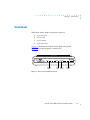
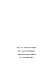
Rear Panel
Figure 1-7 shows the Remote Annex 4000’s rear panel with the
following connectors and switches (Appendix A lists the connectors’
signal/pin allocations):
❑
Console Port.
❑
Diagnostic Jumper.
❑
Printer Port.
❑
Mode Jumper.
❑
Network Interface Connector.
❑
Power Switch.
❑
Power Select Switch.
❑
AC Line Socket.
Remote Annex 4000 Hardware Installation Guide
1-11
Chapter 1
Introduction
Power
Switch
Dress Panel Cover
Console
Port
Printer
Port
Thick
Ethernet
(10Base5)
Twisted Pair
Ethernet
Fan
(10BaseT)
Power
Select
AC Line
Socket
Thin
Ethernet
(10Base 2)
Diagnostic
Jumper
Mode
Jumper
Figure 1-7. Remote Annex 4000 Rear Panel
Rear Panel Components
Console Port
The Remote Annex 4000 has a separate console port with an 8-pin,
RJ-45 connector for attaching the console. The console port provides
access to the ROM Monitor commands when the Remote Annex 4000
is in test mode.
Diagnostic Jumper
This jumper is for Xylogics internal use only.
Printer Port
The Remote Annex 4000 provides a printer port with a 25-pin, female
connector. This port is software-programmable to support a standard
Centronics or Dataproducts parallel printer interface.
1-12
Remote Annex 4000 Hardware Installation Guide
Chapter 1
Mode Jumper
Introduction
The Mode Jumper is used to configure the Remote Annex 4000
properly to ensure compatibility with the operational image. The
Mode Jumper setting is checked by the PROMs only at power-up or
reset time.
The jumper must be installed when running images prior
to Release 9.3. When running Release 9.3 or newer images,
this jumper should be removed.
Network Interface
Connectors
The Remote Annex 4000 comes with an integrated 10Base2, 10Base5,
and 10BaseT auto sense Ethernet connector. Connect to your LAN
using one of the following:
❑
10Base2 (Thin Ethernet) Ethernet port with a BNC connector.
❑
10Base5 (Thick Ethernet) Ethernet transceiver port with a
DB15 connector.
❑
10BaseT (Twisted Pair Ethernet) Ethernet port with an RJ-45
connector.
A Link Indicator LED is provided. This LED is green when an active
10BaseT segment is attached.
Connect only one interface at a time.
The Remote Annex must be reset when changing network
interface connections.
Remote Annex 4000 Hardware Installation Guide
1-13
Chapter 1
Introduction
Power Switch
The Power Switch disconnects AC power without disconnecting the
Remote Annex 4000 from the power source.
Power Select
Switch
The Power Select Switch selects the operational voltage range. The
Remote Annex 2000 automatically selects the operational voltage
range. The 110V position allows operation in the 90 to 130 VAC range;
the 220V position allows operation in the 180 to 260 VAC range.
AC Line Socket
The AC line socket supplies power to the Remote Annex 4000 through
the AC power cord. The AC power cord is plugged into this socket.
Physical Characteristics
The Remote Annex 4000 enclosure has the following characteristics:
❑
Dimensions:
Height: 3.5 in. (89 mm).
Width: 17.5 in. (445 mm).
Depth: 15.5 in. (394 mm).
❑
Weight:
16 lbs (7.3 kg).
❑
Power:
Internal supply.
90–130 VAC, 1.5A.
180–260 VAC, 0.75A.
47–63 Hz, 165W, 563 BTU/hr.
1-14
Remote Annex 4000 Hardware Installation Guide
Chapter 1
❑
❑
Introduction
Environment:
❑
Operating temperature: 0° to 50°C.
❑
Non-operating temperature: -25° to 65°C.
❑
Operating humidity: 5% to 95% relative humidity,
non-condensing.
❑
Non-operating humidity: 5% to 95% relative humidity,
non-condensing.
❑
Operating shock: 10G peak 1/2 sine wave, 11 ms
duration.
❑
Operating vibration: random vibration 1.2 *10-3 G2/Hz,
12 to 198 Hz.
❑
Audible noise: A-Weighted Sound Pressure level less
than 36 dB @ 1 meter from all 6 surfaces.
❑
Operating altitude: 0 to 4,000 meters.
❑
Storage altitude: 0 to 15,000 meters.
❑
Transportation vibration and shock: NSTA project 1A
standard in shipping container.
Approvals:
❑
Meets safety requirements of ETL UL 478, 5th Edition;
CSA C22.2 No. 220-M1986; and EN60950 (1992).
❑
Meets EMI requirements of FCC Class A and EN55022
Class A with shielded and unshielded cables. Meets EMI
requirements of EN55022 Class B with shielded cables.
❑
Meets EMC requirements of EN50082-1.
Remote Annex 4000 Hardware Installation Guide
1-15
Chapter 1
Introduction
❑
MTBF:
68,000 hrs (72 ports), calculated @ 25°C (Mil Std 217).
❑
Rear clearance requirement (for connectors and cables):
6 in. (15 cm).
1-16
Remote Annex 4000 Hardware Installation Guide
Chapter 2
Installing the Remote Annex 4000
T
his chapter contains a description of how to install your Remote
Annex 4000 hardware on your Ethernet network. Installing the
Remote Annex 4000 consists of:
❑
Connecting a LAN.
❑
Connecting a Console Terminal.
❑
Connecting Serial Devices.
❑
Connecting a Parallel Printer.
❑
Powering Up and Testing the Remote Annex 4000.
❑
Installing the Software and Loading the Operational Image.
❑
Auto-initializing the ROMs.
❑
Self-booting the Remote Annex 4000.
❑
Invoking a Console Monitor.
Before you Begin
The Remote Annex 4000’s software and operational image can be
installed on four different devices. Table 2-1 outlines the different
configurations the Remote Annex 4000 supports.
Table 2-1. Remote Annex 4000 Configuration Options
Device on which the Operational
Software and Image is installed
Remote Annex
4000 Must be
Connected to
the Network
Novell Server
Yes
PC on the network
or Console
UNIX Load Host
No
Console
VAX VMS Load Host
Yes
Console
Self-Boot Unit (contains Flash)
No
Console
Input Device used to
Enter Installation
Parameters
Remote Annex 4000 Hardware Installation Guide
2-1
Chapter 2
Installing the Remote Annex 4000
Connecting the Remote Annex to a LAN requires the following
equipment:
❑
The appropriate network cable (e.g., Ethernet transceiver
cable) for connecting to a LAN or an Ethernet loopback
connector.
❑
The console port cable (supplied with software) and a
console terminal.
❑
A PC on the network (Novell boot).
Connecting devices to the Remote Annex 4000 requires:
❑
Remote Annex 4000 fan-out cables for asynchronous
communications.
❑
One parallel printer cable with a 25-pin female connector.
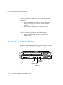
Connecting a LAN Using Ethernet
The Remote Annex 4000 supports three types of Ethernet connections:
Thin Ethernet, Thick Ethernet, or Twisted Pair (see Figure 2-1).
Thick
Ethernet
(10Base5)
Twisted Pair
Ethernet
(10BaseT)
Thin
Ethernet
(10Base 2)
Figure 2-1. Remote Annex 4000 Ethernet Connections
2-2
Remote Annex 4000 Hardware Installation Guide
Chapter 2
Installing the Remote Annex 4000
Each connection type requires a different connection procedure
described in the following sections. Connect only one type of Ethernet
cabling at one time.
Make sure the Remote Annex 4000 is powered off before
disconnecting or connecting the Ethernet cabling.
The following subsections contain a description of how to connect
your Remote Annex 4000 to:
❑
Thin Ethernet (10Base2).
❑
Thick Ethernet (10Base5).
❑
Twisted Pair (10BaseT).
Connecting Thin Ethernet (10Base2) Cable
To connect Thin Ethernet (10Base2) or equivalent cable, you must use
a T-connector. The T-connector is installed in your Ethernet network
cable. Follow these steps to connect the Remote Annex 4000 to a Thin
Ethernet cable (see Figure 2-2):
1
Verify that both sides of the T-connector are connected to the Thin
Ethernet cable.
If the Remote Annex 4000 is the last device on the Thin Ethernet
segment, make sure that one side of the T-connector is connected
to the cable and the other side is connected to a network
terminator.
2
Plug the T-connector on the Thin Ethernet cable (RG-58 coaxial
cable) into the 10Base2 Ethernet connector located on the rear
panel of the Remote Annex 4000.
Remote Annex 4000 Hardware Installation Guide
2-3
Chapter 2
Installing the Remote Annex 4000
3
Twist the sleeve on the T-connector clockwise to lock the connection
in place.
Figure 2-2. Connecting Thin Ethernet Cable
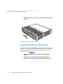
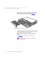
Connecting Thick Ethernet (10Base5) Cable
To connect Thick Ethernet (10Base5) or equivalent transceiver cable,
you must have already installed a 10Base5 Ethernet network cable.
Follow these steps to connect the Remote Annex 4000 to a Thick
Ethernet cable (see Figure 2-3):
2-4
1
Make sure the transceiver cable is plugged into the Ethernet
network.
2
Push the slide mechanism on the Remote Annex 4000’s Thick
Ethernet connector to the right and plug in the transceiver cable.
Remote Annex 4000 Hardware Installation Guide
Chapter 2
3
Installing the Remote Annex 4000
Push the slide mechanism to the left to secure the connection.
Figure 2-3. Connecting Thick Ethernet Cable
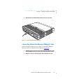
Connecting Twisted Pair Ethernet (10BaseT) Cable
Follow the steps in this section to connect Twisted Pair (10BaseT)
Ethernet cable to the Remote Annex 4000 (see Figure 2-4):
1
Insert the RJ-45 connector located on the Twisted Pair Ethernet cable
into the 10BaseT connector on the rear panel of the Remote Annex.
2
When the connector clicks into place, the connection is secure.
Remote Annex 4000 Hardware Installation Guide
2-5
Chapter 2
Installing the Remote Annex 4000
3
Verify that the Link Indicator is green.
The green link indicator LED next to the 10BaseT connector goes
on when power is applied and an active 10BaseT network
segment is plugged in.
Do not confuse this connector with the console
port RJ-45 connector.
Figure 2-4. Connecting Twisted Pair Ethernet Cable
2-6
Remote Annex 4000 Hardware Installation Guide
Chapter 2
Installing the Remote Annex 4000
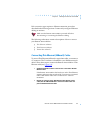
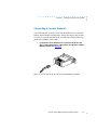
Connecting a Console Terminal
A console terminal is used to access the ROM Monitor and boot the
Remote Annex 4000 for the first time. Follow the steps in this section
to connect a console terminal to the console port located on the rear
panel of the Remote Annex 4000.
1
Connect the Console Terminal’s I/O connector to the RJ-45 cable
(the accessory kit includes a cable) using a Telco RJ wire to a DB-25
DTE drop adapter (see Figure 2-5).
Figure 2-5. Connecting the RJ-45 Cable to the DB-25 DTE Drop Adapter
Remote Annex 4000 Hardware Installation Guide
2-7
Chapter 2
Installing the Remote Annex 4000
2
Plug the RJ-45 connector into the console port located on the back
panel of the Remote Annex 4000 (Figure 2-6).
When the connector clicks into place, the connection is secure.
Appendix A describes the console port’s signal/pin allocation.
Figure 2-6. Connecting to a Console Terminal
3
Turn on the Console Terminal and set the terminal to 9600 baud,
eight data bits, no parity, one stop bit, and XON/XOFF flow control.
The ROM Monitor assumes that this terminal is CRT-based and
displays the backspace (BS) character accordingly. See Chapter
3 for information on invoking the ROM monitor.
2-8
Remote Annex 4000 Hardware Installation Guide
Chapter 2
Installing the Remote Annex 4000
After the Remote Annex 4000 boots, you can invoke a console monitor
by pressing Return . At the console monitor prompt, entering help
displays the available options. See Chapter 3 for information on the
ROM Monitor commands.
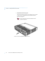
Connecting Serial Devices
The Remote Annex 4000 provides three to twelve 50-pin PBX
connectors (depending on the port configuration) for attaching 1 to
72 devices using Remote Annex 4000 asynchronous (fan-out) cables.
To attach the cables:
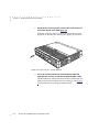
1
Remove the dress panel cover by sliding it forward. This cover is
located on the top rear of the Remote Annex 4000 (see Figure 2-7).
Dress Panel Cover
Figure 2-7. Removing the Remote Annex 4000 Dress Panel Cover
Remote Annex 4000 Hardware Installation Guide
2-9
Chapter 2
Installing the Remote Annex 4000
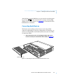
2
Loosen the screws that secure the cable retainer and slide the cable
retainer back to allow room for the cable (see Figure 2-8).
Cable Retainer
Figure 2-8. Moving the Cable Retainer to Make Room for the Cable
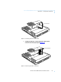
3
Attach the PBX end of the fan-out cable to the PBX connector
(see Figure 2-9).
PBX End
of Cable
Figure 2-9. Attaching the Cable to the PBX Connector
2-10
Remote Annex 4000 Hardware Installation Guide
Chapter 2
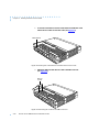
4
Installing the Remote Annex 4000
Tighten the screw on the PBX end of the cable (see Figure 2-10).
PBX Screw
Figure 2-10. Securing the PBX Cable
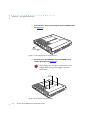
5
Slide the cable retainer forward, making sure that the lip of the
retainer secures the connector (see Figure 2-11).
6
Tighten the screws that secure the cable retainer.
Cable Retainer Screw
Figure 2-11. Securing the PBX Connector
Remote Annex 4000 Hardware Installation Guide
2-11
Chapter 2
Installing the Remote Annex 4000
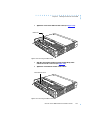
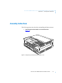
7
Slide the dress panel cover back to its original position by sliding it
toward the front of the Remote Annex 4000 (see Figure 2-12).
Dress Panel Cover
Figure 2-12. Securing the Dress Panel Cover
If the cables are shielded (metal), the cable retainers may obstruct
the PBX end, preventing you from securing the dress panel cover.
You may need to remove the cable retainers.
8
Connect the Remote Annex 4000 fan-out cables to your serial
devices.
See Appendix B for a description of the fan-out cable.
Shielded cables are required for compliance with
VDE EMI limits.
2-12
Remote Annex 4000 Hardware Installation Guide
Chapter 2
Installing the Remote Annex 4000
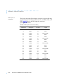
Remote Annex 4000 Serial Cables
The Remote Annex 4000 asynchronous serial interfaces conform to
RS232 specifications. However, it is possible to exceed the
specifications’ cable limits given good quality cables that are run in
an electrically quiet environment. Xylogics only guarantees operation
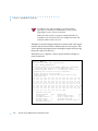
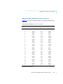
with the cable lengths recommended below (see Table 2-2).
The Remote Annex 4000 can incur damage if the cables are hit
by lightning.
Table 2-2. Recommended Cable Lengths
Line Speed: bps
Cable Length: Feet
Meters
50–19,200
250
75
38,400
200
60
57,600
100
30
115,200
50
15
If you exceed these recommended cable lengths, you must
compensate for any resulting electrical problems. Exceed these
distances at your own risk.
Remote Annex 4000 Hardware Installation Guide
2-13
Chapter 2
Installing the Remote Annex 4000
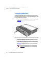
Connecting a Parallel Printer
The Remote Annex 4000 supports parallel printer interface cables
from Dataproducts and Centronics. Connect the Remote Annex 4000
to your parallel printer as follows:
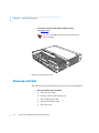
1
Connect one end of the Dataproducts or Centronics parallel printer
cable to the Remote Annex 4000’s 25-pin printer port (see
Figure 2-13).
Figure 2-13. Connecting the Parallel Printer Cable to the Remote Annex 4000
2
Secure the connection by tightening the screws that connect the
cable to the printer port.
3
Connect the other end of the Dataproducts or Centronics parallel
printer cable to your printer.
Appendix A details the printer port’s signal/pin allocations.
Dataproducts printers do not use standard cables.
Appendix B describes the cables for the Remote
Annex 4000.
2-14
Remote Annex 4000 Hardware Installation Guide
Chapter 2
Installing the Remote Annex 4000
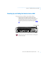
Powering Up and Testing the Remote Annex 4000
Power-up and test your Remote Annex 4000 as follows:
1
Verify the Remote Annex 4000’s operational power range.
Check that the power select switch is set to the 110V position
for operation in the 90 to 130 VAC range, or to the 220V
position for operation in the 180 to 260 VAC range (see Figure
2-14).
Power Select Switch
Figure 2-14. Verifying the Remote Annex 4000 Operational Power Range
Setting the power select switch incorrectly can damage the
Remote Annex 4000.
Remote Annex 4000 Hardware Installation Guide
2-15
Chapter 2
Installing the Remote Annex 4000
2
Apply power.
Connect the female end of the power cord to the AC line socket.
Connect the male end to an active AC line outlet (see Figure 215). Turn the Power switch on.
Figure 2-15. Connecting the Power Cord
The Remote Annex 4000 now runs its ROM-resident power-up
diagnostics. The LEDs light and then turn off, except for the
Power and some status LEDs.
2-16
Remote Annex 4000 Hardware Installation Guide
Chapter 2
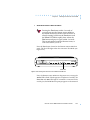
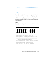
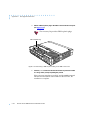
3
Installing the Remote Annex 4000
Set the Remote Annex 4000 to Test Mode.
Pressing the Test button within 3 seconds of
powering up puts the Remote Annex 4000 into
test mode. To enter test mode when the Annex is
already running, hold down the Test button until
the Power LED blinks rapidly, then release the
Test button and press it again within 3 seconds.
This second method resets the Remote Annex, so
warn users before you do it.
Press the Test button located on the Remote Annex 4000 front
panel. The Test LED lights when the unit enters Test Mode (see
Figure 2-19).
STATUS
POWER
UNIT
NET
ATTN
LOAD
ACTIVE
1
2
3
4
5
6
7
8
TEST
Test Button
Figure 2-16. Setting the Remote Annex 4000 to Test Mode
Next, the Remote Annex 4000 runs diagnostic tests, causing the
Active LED to flash. If the diagnostics complete successfully, the
Unit, Net, and Attn LEDs light. If a terminal is connected to the
console port, the ROM Monitor prompt appears on the terminal.
Remote Annex 4000 Hardware Installation Guide
2-17
Chapter 2
Installing the Remote Annex 4000
If the Unit, Net, and Attn LEDs do not light within one minute,
one of the following failures has occurred:
❑
Remote Annex 4000 hardware failure: Unit and Attn
LEDs flash. Contact technical support.
❑
Network or network interface failure: Net and Active
LEDs flash; error message displays on the console.
If a network or network interface failure occurs, typing q accesses the
ROM Monitor prompt. Check the network connection (also, see net
on page 3-22). Chapter 4 provides additional troubleshooting
information.
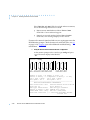
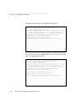
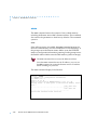
4
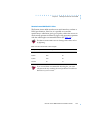
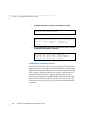
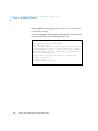
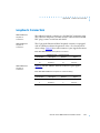
Verify the Remote Annex 4000’s hardware configuration.
At the monitor prompt on the console, type config and press
Return . The screen display looks like this:
monitor:: config
1-6
7-12 13-18 19-24 25-30 31-36
RS232 RS232 RS232 RS232 RS232 RS232
37-42 43-48 49-54
RS232 RS232 RS232
Number of Ports = 36 Number of Ports = 18
Amount of Memory = 1.5 MegAmount of Memory = 1.5 Meg
SLC 1 Type = VFSLC
SLC 2 Type = VFSLC
Max Speed = 115.2
Max Speed = 115.2
----------------------------------------------------REVISION/CONFIGURATION INFORMATION
ROM Software Rev: 0901
Ethernet Add:00-80-2D-00-B5-9D
Board ID: 46
Major HW Rev: 4
MLB Type: Enhanced Ext
MLB CPU Type: 486SXLC2
Amount of memory: 6 Meg EEPROM size: 65504
FLASH PROM size: 2 Meg
MFG IDs: (8989,8989)
Available Interfaces (* = selected):*ThickNet ThinNet
Twisted Pair
2-18
Remote Annex 4000 Hardware Installation Guide
Chapter 2
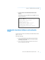
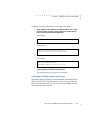
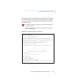
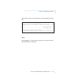
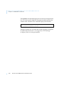
5
Installing the Remote Annex 4000
Record the Remote Annex 4000’s Ethernet address for future
reference.
At the monitor prompt, type addr -d and press
display looks like this:
Return
. The screen
monitor:: addr -d
Ethernet address (hex): 00-80-2D-00-18-B6
Internet address: <uninitialized>
Subnet mask: 255.255.0.0
Broadcast address: 0.0.0.0
Preferred Load Host address: <any host>
Preferred Dump Host address: 0.0.0.0
Load/Dump Gateway address: 0.0.0.0
Type of IP packet encapsulation: <ethernet>
Load Broadcast: Y
Installing the Operational Software and Loading the
Image
Use this section if you have successfully connected the Remote Annex
4000 to your LAN.
This section describes:
❑
How to install the Remote Annex 4000’s operational software
and image on a device that resides on a network accessible
to the Remote Annex 4000.
❑
How to download the operational image from the network
device to the Remote Annex 4000.
Remote Annex 4000 Hardware Installation Guide
2-19
Chapter 2
Installing the Remote Annex 4000
This section contains the following subsections:
❑
Installing to and Loading from a Novell Server.
❑
Installing to and Loading from a UNIX Host.
❑
Installing to and Loading from a VAX VMS Host.
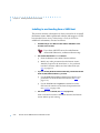
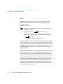
Installing to and Loading from a Novell Server
This section contains a description of what you need to do to install
the Remote Annex 4000’s operational software and image to a Novell
Server. Proceed as follows:
1
Log into your Novell server as SUPERVISOR or equivalent.
2
Insert the Network Administrator Program Install Disk into your PC’s
floppy drive.
3
Change to your PC’s floppy drive (usually drive A or B).
4
Display or print the README.TXT file for updated information about
the current version of Annex Manager for DOS software.
5
Type INSTALL and press
Enter
.
A list of your PC’s available drives appears.
6
Select a network drive that is accessible to all users on the network
and press Enter .
7
Enter the name of the directory where you want to copy the files or
select the default \PUBLIC directory and press Enter .
The installation program copies each file from the
Administrator’s Install Disks to the network drive and directory
you specified in Steps 5 and 6. The installation program then
decompresses and verifies each file being copied. See the Annex
Manager for DOS Administrator’s Guide for the PC for a list and
description of the Administrator’s files.
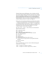
8
2-20
Power up or reset the Remote Annex 4000. Do not enter test mode.
Remote Annex 4000 Hardware Installation Guide
Chapter 2
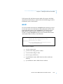
9
Installing the Remote Annex 4000
Run the Annex Installation Utility. At the prompt, start the Annex
Installation Utility by typing:
AMINSTAL
Enter
A window appears with selections for installing or upgrading
the software.
10
Select Install and press
Enter
.
The Annex Installation utility automatically lists any uninstalled
Annexes in the Uninstalled Annexes window.
11
Use the arrow keys or the mouse to highlight the Annex(es) to be
installed and select OK.
A list of available servers appears.
To install several Remote Annexes, select each
Remote Annex and press Enter .
12
Choose the server that contains the operational code that will be
downloaded to the Annex(es) and select OK.
A message appears when the installation is complete. If any
errors occur during the process, an error message window
appears.
13
Now you can run the Annex Manager, which configures the
Annex(es) and security. See the Annex Manager for DOS
Administrator’s Guide for the PC for information about Annex
Manager.
If a Remote Annex 4000 boots from a Novell server, the Remote
Annex is available for IPX dial-in and dial-out only. Other
Remote Annex 4000 features such as PPP, SLIP, ARAP, and CLI
are not supported.
Remote Annex 4000 Hardware Installation Guide
2-21
Chapter 2
Installing the Remote Annex 4000
Installing to and Loading from a UNIX Host
This section contains a description of what you need to do to install
the Remote Annex 4000’s operational software and image to a UNIX
host (see the Remote Annex Administrator’s Guide for UNIX for
additional information). Proceed as follows:
1
Install the image on a UNIX host. The software installation notes
describe how to do that.
If you have a BOOTP server, boot the Remote
Annex 4000. Otherwise, continue to the next step.
2
3
4
Execute the ROM Monitor addr command:
❑
Enter the Remote Annex 4000’s Internet address.
❑
Modify any other parameters that the Remote Annex
4000 may require for the initial boot, i.e., the preferred
load host’s Internet address and the subnet mask (see
addr on page 3-5).
If you are booting the Remote Annex 4000 using a Serial Line Internet
Protocol (SLIP) network interface, you must:
❑
Use the ROM Monitor slip command to modify the port
parameters for the SLIP network interface (see slip on
page 3-31).
❑
Use the ROM Monitor sequence command to list the
SLIP network interface in the load/dump interface list
(see sequence on page 3-29).
Execute the boot command (see boot on page 3-8).
After successful execution of the boot command, the Remote
Annex 4000 is up and running.
2-22
Remote Annex 4000 Hardware Installation Guide
Chapter 2
Installing the Remote Annex 4000
Installing to and Loading from a VAX VMS Host
This section contains a description of what you need to do to install
the Remote Annex 4000’s operational software and image on a VAX
VMS Load Host. Refer to the Annex Interface for VMS Environments
Administrator’s Guide and the Annex Interface for VMS Environments
User’s Guide for additional information.
This product cannot be installed on an AXP system. This section
contains the following subsections:
❑
Installing the Operational Software and Image on a VAX VMS
Load Host.
❑
Configuring NCP for Downloading.
❑
Configuring for Crash Dump Support.
❑
Customizing for Multiple Remote Annex Images.
Installing the Operational Software and Image on a VAX VMS Load
Host
Prerequisites
The following should be in place before you install the software and
image on your load host.
❑
Your load host must be running VMS 5.5 (or higher).
❑
Your load host must be running DECnet VAX.
❑
The Ethernet controller must be on the same Ethernet as the
Annex.
❑
The CMKRNL and SYSPRIV privileges must be enabled.
Remote Annex 4000 Hardware Installation Guide
2-23
Chapter 2
Installing the Remote Annex 4000
❑
The load host has at least 4000 blocks of available disk space
(on any disk), and up to an additional 17,000 blocks available
(depending on the amount of memory installed in the
Annex) if dumps are to be supported.
In a VMS environment, dumps do not overwrite
each other, as VMS allows multiple versions of
the same file. Therefore, up to 17,000 blocks of
memory must be available for each Remote
Annex 4000 dump.
Installation
❑
The system is backed up before installing the software.
❑
The software medium is mounted on an appropriate device
drive, unless you are installing from save sets copied from
another load host.
Perform the following steps to install the software and image on your
system load host. To stop the installation at any time, press CTRL-Y
(^Y).
1
Log into the system manager account.
2
Enter @SYS$UPDATE:VMSINSTAL to start VMINSTAL.
VMINSTAL lists any active processes and asks if you want to
continue.
2-24
3
Enter yes and continue the installation.
4
Enter yes if you have backed up your system disk.
5
Enter the device on which your distribution medium is loaded.
6
Enter * for the products to be processed.
7
Press
8
Enter yes if you’ve mounted the software medium on the
appropriate device.
Return
to indicate none for installation options.
Remote Annex 4000 Hardware Installation Guide
Chapter 2
Installing the Remote Annex 4000
The Remote Annex parameter disabled_modules disables
specified software modules and frees memory space for use by
the system.
The default Remote Annex setting for disabled_modules
includes vci which disables the Remote Annex interface for
VMS environments along with the following commands:
backwards, change, clear, crash, define, disconnect, forward,
list, logout, resume, set, and show.
Booting the Remote Annex 4000 from a VAX VMS load host
automatically enables vci. The following message appears in
the syslog file: MOP Booting, vci enabled. On subsequent boots
(regardless of the type of load host; e.g., VMS or UNIX), vci
remains enabled. To disable vci, you must re-enter it in the
disabled_modules parameter (for more details, see the Remote
Annex Administrator’s Guide for UNIX).
If the disabled_modules parameter is set to vci, even if the
cli_interface parameter is set to vci, none of the VMS-specific
commands will be available, the Local > prompt will not be
displayed, and the Username> prompt will not appear upon
port reset.
Configuring NCP for Downloading
The operational image now resides in the directory to which the
logical MOM$LOAD points. You must now enable downline loading
of the image on the appropriate circuit using NCP.
Remote Annex 4000 Hardware Installation Guide
2-25
Chapter 2
Installing the Remote Annex 4000
1
To find the appropriate circuit, type the following command:
$MCR NCP SHOW KNOWN CIRCUITS
The system responds:
Known Circuit Volatile Summary as of 25-May-1993
Circuit
State
Loopback
Adjacent
Name
Routing Node
SVA-0
on
2
Go back into NCP and enable that circuit to honor service requests
by issuing the following NCP commands:
$MCR
$MCR
$MCR
$MCR
NCP
NCP
NCP
NCP
SET
SET
DEF
SET
CIRCUIT
CIRCUIT
CIRCUIT
CIRCUIT
SVA-0
SVA-0
SVA-0
SVA-0
STATE OFF
SERVICE ENABLED
SERVICE ENABLED
STATE ON
Configuring for Crash Dump Support
The VAX VMS load host can be set up to accept crash dumps from
the Remote Annex at any time. To enable this feature, you must assign
a DECnet node name and address to your Remote Annex and set up
NCP to point to a directory that will receive the crash dumps. You
will need the Remote Annex’s Ethernet address before you can
execute these commands. The show server command displays the
Remote Annex’s Ethernet address. See the Annex Interface for VMS
Environments Administrator’s Guide for more information about this
command.
2-26
Remote Annex 4000 Hardware Installation Guide
Chapter 2
Installing the Remote Annex 4000
To enable your VAX VMS load host to accept crash dumps:
1
Assign a DECnet node number to your Remote Annex. You can pick
any node number or name as long as it does not conflict with any
node or address already defined within NCP.
For example:
$MCR NCP SET NODE 2.69 NAME BINGO
2
Assign a directory and file to receive the crash dump.
For example:
$MCR NCP SET NODE BINGO DUMP FILE\
DKA200:[ZETKIN.ANNEX_CRASH]BINGO.DMP
3
Assign the Remote Annex’s hardware address to the node name.
For example:
$MCR NCP SET NODE BINGO\
HARDWARE ADDRESS 00-80-2D-00-1A-DE
4
Issue the equivalent define commands so this crash dump support
continues when your VMS load host is restored.
The VMS load host now supports crash dumps.
Customizing for Multiple Remote Annex Images
The Remote Annex operational code is installed in MOM$LOAD as
OPER_46_ENET.SYS. The Remote Annex does not require that this
be the exact file name and you may want to keep multiple versions
of the Remote Annex software.
Remote Annex 4000 Hardware Installation Guide
2-27
Chapter 2
Installing the Remote Annex 4000
You can rename Remote Annex operational images, but they must
remain in MOM$LOAD. If you do change the operational image name
from OPER_46_ENET.SYS to some other name, the new file name plus
the extension can be no longer than 16 characters total. This is due to
a MOP restriction of 16 characters in passing the load file name field.
Auto-initializing the ROMs
The Remote Annex 4000 is distributed without an IP address or
preferred load host (UNIX/IP, IPX, or MOP) defined in ROM. When
the device is booted, the Remote Annex 4000 attempts to autoinitialize its ROMs using BOOTP (bootstrap protocol) and RARP
(Reverse Address Resolution Protocol).
The Remote Annex 4000 supports the BOOTP and RARP protocols.
Use these protocols to automatically obtain boot information from a
UNIX host without requiring any manual set-up on the Remote
Annex 4000.
❑
BOOTP allows a diskless client to determine its IP address,
the IP address of the server, and the name of the file to be
loaded into memory.
❑
RARP maps a hardware address into an IP address.
The ROMs invoke this system of acquiring boot information when a
boot is initiated and the Remote Annex 4000 is not initialized. Under
this condition, the Remote Annex 4000 first tries to get boot
information via BOOTP or RARP.
If BOOTP and RARP fail, the Remote Annex 4000 attempts to load an
image by transmitting an IPX advertisement request for service and
a MOP multicast boot request.
2-28
Remote Annex 4000 Hardware Installation Guide
Chapter 2
Installing the Remote Annex 4000
If all requests fail, the Remote Annex 4000 will return to the ROM
monitor (if in Test mode) or continue the auto-initializing procedure
indefinately (if in normal mode).
BOOTP
For a successful BOOTP retrieval, a bootpd must be running on a host
on the same network as the Remote Annex 4000 and must have the
appropriate information in the bootptab file. The Remote Annex
4000’s BOOTP implementation adheres to rfc951, rfc1048, and
rfc1084. A sample bootptab file entry used to initialize the Remote
Annex 4000 named terminator looks like this:
remoteannexdefault:\
:sm=255.255.255.0:gw=132.245.22.66:\
:hn:vm=auto:to=-18000:
terminator:\
:ht=1:ha=00802d004879:ip=132.245.22.226:\
:tc=remoteannexdefault:
In the previous example:
❑
sm is the subnet mask.
❑
gw is the load/dump gateway address.
❑
vm is the Vendor Magic Cookie.
❑
ht is host type (1=Ethernet).
❑
ha is the Remote Annex 4000’s hardware address (Ethernet
Address).
❑
ip is the Remote Annex 4000’s Internet Address.
Remote Annex 4000 Hardware Installation Guide
2-29
Chapter 2
Installing the Remote Annex 4000
When the Remote Annex 4000 receives a BOOTP response with the sm,
gw, and ip set, it sets the respective parameters: subnet_mask,
load_dump_gateway, and inet_addr. The Vendor Magic Cookie
must be set to auto. This indicates that bootpd should respond to the
client (Remote Annex 4000 in this case) with whatever format the
client requests; the Remote Annex 4000 (client) always makes requests
in the decimal dot notation format (e.g., 99.130.83.99).
The bootpd adds the address of the host on which it is running as the
Server Address in the bootp response message. The ROMs use the
Server Address as the preferred load host and store it in the
pref_load_addr parameter.
The bootpd must be running on the Remote Annex 4000’s
preferred load host.
RARP
If the Remote Annex 4000 does not receive a successful BOOTP
response, it uses RARP to get the boot information. For a successful
RARP retrieval, TCP/IP must be running on a host that is on the same
network as the Remote Annex 4000, and the host’s ARP table must
be initialized with the Remote Annex 4000’s Internet and Ethernet
addresses (see the arp man page, arp –s).
The only boot information that RARP provides is the Remote Annex
4000’s Internet address. The ROMs save this information in the
inet_addr parameter. The ROMs use default information for the
subnet mask and preferred load host. This means the ROMs will
broadcast their requests.
The host serving the Remote Annex 4000 its boot information must
be running on the same network as the Remote Annex 4000 because
the Remote Annex 4000 only broadcasts BOOTP and RARP queries.
2-30
Remote Annex 4000 Hardware Installation Guide
Chapter 2
Installing the Remote Annex 4000
If BOOTP and RARP fail, the Remote Annex 2000 transmits an IPX
Advertisement Request for Service and a MOP Multicast boot request.
If all requests fail, the Remote Annex 4000 returns to the ROM monitor
(if in Test mode) or continues the auto-initializing procedure
indefinitely (if in normal mode).
Self-booting the Remote Annex 4000
If you purchased a Remote Annex 4000 with Flash ROM, your device
already contains an operational image. You can check your Remote
Annex 4000’s configuration by entering the config command at the
monitor prompt. The config command displays the current
configuration information and revision levels. If your device has Flash
ROM installed, the line FLASH PROM size: will appear under the
REVISION/CONFIGURATION INFORMATION section.
This section describes how to boot your Remote Annex 4000 from
Flash ROM. Proceed as follows:
1
Enter the ROM Monitor prompt from the Console.
2
Set the Internet address to a valid IP address and the subnet mask to
a valid mask using the addr command.
3
Set the interface sequence to self using the sequence command.
4
Boot the Annex.
Remote Annex 4000 Hardware Installation Guide
2-31
Chapter 2
Installing the Remote Annex 4000
Invoking the Console Monitor
After the image boots, you can invoke a Console Monitor by pressing
Return on the console. At the Console Monitor prompt, entering help
or ? displays the available options:
2-32
❑
dump (from the Remote Annex to the host and reboots).
❑
help or ? (displays the available options).
❑
info (displays configuration information for the Remote
Annex).
❑
leds (displays the current front panel LED status).
❑
quit (exit the Console Monitor, e.g., quiet the console).
❑
reboot filename (reboots the Remote Annex).
❑
rom (returns the Remote Annex to the ROM Monitor).
❑
syslog (displays syslog messages).
Remote Annex 4000 Hardware Installation Guide
Chapter 2
Installing the Remote Annex 4000
Remote Annex 4000 Hardware Installation Guide
2-33
Chapter 2
2-34
Installing the Remote Annex 4000
Remote Annex 4000 Hardware Installation Guide
Chapter 3 ROM Monitor Commands
T
his chapter describes the ROM Monitor commands. Access these
commands through a terminal connected to the console port when
the Remote Annex 4000 is intest mode.
Pressing the Test button within 3 seconds of powering up puts
the Remote Annex 4000 into test mode. To enter test mode
when the Annex is already running, hold down the Test button
until the Power LED blinks rapidly, then release the Test button
and press it again within 3 seconds. This second method resets
the Annex, so warn users before you do it.
If you try to access the ROM monitor and receive a password
prompt, contact your system administrator. The ROM monitor
is password protected.
The ROM Monitor commands allow you to set a subset of the
configuration (EEPROM) parameters. Some of these parameters, like
the unit’s IP address, are required for booting the Remote Annex 4000;
some parameters, like the broadcast address, are required if the
network configuration differs from the supplied defaults. Table 3-1
lists the ROM Monitor commands.
Other parameters, although not required, are recommended for the
Remote Annex 4000’s initial boot. Setting these parameters, rather
than using the assigned defaults, minimizes errors during the initial
boot. For example, setting the parameter that defines the preferred
load host enables the Remote Annex 4000 to load by requesting
assistance from a specific host, rather than by broadcasting that
request to all hosts on the subnet.
After the Remote Annex has booted, you can define the same
parameters you defined using the ROM monitor, by using the na
utility, the local CLI admin command, or SNMP (for more details, see
the Remote Annex Administrator’s Guide for UNIX).
Remote Annex 4000 Hardware Installation Guide
3-1
Chapter 3
ROM Monitor Commands
ROM Monitor commands generally provide data about a subset of
current configuration (EEPROM) parameters. When appropriate,
they also display a prompt that allows the operator to change those
parameters. Default or current values for parameters are displayed
in brackets. For example:
Enter broadcast address [132.245.6.255]:
At the prompt, enter a different value, or press
displayed value unchanged.
Return
to leave the
You can use unique abbreviations for all ROM Monitor commands
except erase. For example, enter boot as bo, and enter net as n. If you
enter an abbreviation that is not unique, an error message describing
the command as ambiguous is displayed on the console terminal.
Command Descriptions
Table 3-1 lists the ROM Monitor commands; the following subsections
describe them.
Table 3-1. ROM Monitor Commands
Command
Description
Use
addr [-d]
Displays and sets
EEPROM values
relevant to IP network
addressing, including
the unit’s IP address.
Changing IP
configuration
parameters.
boot [-v] [<file>]
Manually boots and
loads the unit’s
operating code.
Changing the address of
the boot image.
(continued on next page)
3-2
Remote Annex 4000 Hardware Installation Guide
Chapter 3
ROM Monitor Commands
Table 3-1. ROM Monitor Commands (continued)
Command
Description
Use
boot [-l] [<file>]
Erases the existing
Flash memory and
copies a new image to
Flash.
Upgrading or
replacing the Flash
image.
config
Displays the current
hardware
configuration and
revision levels.
Identifying your
hardware, memory,
and ROM versions.
console-baud
Changes the console
port’s baud rate.
Configuring the
console port for
remote maintenance.
erase
Erases non-volatile
memory.
Loading a new image
and need to erase the
old image.
help
Displays the list of
ROM Monitor
commands.
Referencing the ROM
monitor commands.
image [-d | <file>]
Displays and/or sets
the load image and
tftp load dump
names.
Loading an image
that differs from the
default.
ipx [-d]
Displays and sets
EEPROM values
relevant to Novell/
IPX network
addressing, including
the IPX load/dump
file server.
Changing Novell/IPX
configuration
parameters.
lat_key [-d]
Sets the LAT key.
Connecting to a DEC
VMS host.
(continued on next page)
Remote Annex 4000 Hardware Installation Guide
3-3
Chapter 3
ROM Monitor Commands
Table 3-1. ROM Monitor Commands (continued)
3-4
Command
Description
Use
mop [-d]
Displays and sets
EEPROM values
relevant to VAX/VMS
network addressing,
including the MOP
load/dump address.
Loading software
from a DEC VMS
host.
net
Executes an Ethernet
transceiver loopback
test.
Checking your
Ethernet
connection.
option_key [-d]
Sets or displays the
option key.
Checking your
option key setting.
ping
Sends ICMP
ECHO_REQUEST
datagram to a host or
gateway.
Checking to see if a
host or gateway
can be reached.
ports [-d]
Shows the current
status of all ports.
Checking a port.
sequence [-d | <list>]
Displays and edits the
load/dump interface
list.
Checking or
changing the load/
dump interface
list.
slip [-d] [<port>]
Defines a serial port as
a Serial Line Internet
Protocol (SLIP)
network interface.
Checking or
changing a serial
port’s settings.
stats [-slip]
Displays current
network statistics
gathered by the ROM.
Checking the
network resources.
Remote Annex 4000 Hardware Installation Guide
Chapter 3
ROM Monitor Commands
addr
The addr command displays and sets several Remote Annex 2000
operating parameters (EEPROM values) relevant to IP network
addressing:
❑
Internet address.
❑
Subnet mask.
❑
Broadcast address.
❑
Preferred Load Host address.
❑
Preferred Dump Host address.
❑
Load/Dump Gateway address.
❑
Type of IP Packet encapsulation.
❑
Load Broadcast
The addr -d command displays the unit’s ROM-resident Ethernet
address in hexadecimal notation. (For a description of Internet
addresses, see the Remote Annex Administrator’s Guide for UNIX.) The
command syntax is:
addr [–d]
If you enter the addr command without the –d argument, the console
prompts you for each Internet address. Enter Internet addresses using
the standard decimal dot (.) notation.
The addr –d command displays the Remote Annex 4000’s Ethernet
address, IP address, subnet mask, broadcast address, preferred load
host address, preferred dump host address, load/dump gateway
address, IP encapsulation type, and Load Broadcast. The addr -d
command cannot be used to make changes to any of the displayed
parameters.
Remote Annex 4000 Hardware Installation Guide
3-5
Chapter 3
ROM Monitor Commands
The addr command display looks like this:
monitor:: addr
Enter Internet address [<uninitialized>]:: 192.9.200.214
Internet address: 192.9.200.214
Enter Subnet mask [255.255.0.0]::
Enter Broadcast address [0.0.0.0]:: 192.9.200.0
Broadcast address: 192.9.200.0
Enter Preferred Load Host address [<any host>]::
192.9.200.88
Preferred Load Host address: 192.9.200.88
Enter Preferred Dump Host address [0.0.0.0]::
192.9.200.88
Preferred Dump Host address: 192.9.200.88
Enter Load/Dump Gateway address [<uninitialized>]::
192.9.200.10
Load/Dump Gateway address: 192.9.200.88
Select type of IP packet encapsulation (ieee802/ethernet)
[<ethernet>]::
Load Broadcast Y/N [Y]::
The addr -d command display looks like this:
monitor:: addr -d
Ethernet address (hex): 00-80-2D-00-18-B6
Internet address: 192.9.200.214
Subnet mask: 255.255.0.0
Broadcast address: 192.9.200.0
Preferred Load Host address: 192.9.200.88
Preferred Dump Host address: 192.9.200.88
Load/Dump Gateway address: 192.9.200.10
Type of IP packet encapsulation: <ethernet>
Load Broadcast: Y
3-6
Remote Annex 4000 Hardware Installation Guide
Chapter 3
ROM Monitor Commands
The Remote Annex 4000 must have an Internet (IP) address in its
memory before it can load its operational image across the Ethernet
via the IP protocol. Therefore, you must enter the IP address before
booting the Remote Annex 4000 from a UNIX load host. If you do not
define a subnet mask, the Remote Annex 4000 uses the generic mask
for the specified IP address.
The Remote Annex 4000 tries to boot from a preferred UNIX load
host. If you do not define a preferred load host, the Remote Annex
4000 broadcasts its load request and loads software from the first host
that responds.
If the part of the IP address containing the network address differs
from that of the preferred load or dump host, the host must be reached
through a gateway. The addr command prompts you for this
gateway’s IP address.
The Remote Annex 4000 uses the broadcast address parameter when
loading a file. If this parameter contains a specific address (for
example, 132.245.6.255), the Remote Annex 4000 uses only that
address for broadcast. If the value is all zeroes (0.0.0.0), the ROM
Monitor tries various combinations of broadcast addresses and
subnet or network broadcasts. The Remote Annex 4000 broadcasts its
request three times for each possible combination of broadcast
addresses.
You can specify the IP encapsulation type as either ethernet for
Ethernet, or ieee802 for IEEE 802.2/802.3. The default IP
encapsulation is ethernet. Many systems have hardware Ethernet
interfaces that are IEEE 802.3 compliant, but very few actually do
802.3 IP packet encapsulation.
Do not change this parameter unless you know absolutely that
your Ethernet does 802.2/802.3 IP packet encapsulation. An
incorrect IP encapsulation type prevents your Remote Annex
from booting.
Remote Annex 4000 Hardware Installation Guide
3-7
Chapter 3
ROM Monitor Commands
boot
The boot command requests the loading of appropriate Remote
Annex 4000 operating software from a cooperating host. The
command syntax is:
boot [–lv | filename]
The boot –l command is supported only if the self-boot option
(Flash) is installed.
Typing the letter q or
Control
-C interrupts the boot.
If you try to boot with a non-existent image file name, the
Annex will hang as it searches for the image. You must press
the Reset button to recover.
A successful boot disables the ROM Monitor.
The boot command accepts a file name for the Remote Annex 4000’s
image. If the file name is not specified, boot displays the default file
name and prompts for one. If you do not provide a file name, or have
not defined one for the Remote Annex 4000, boot requests the default
oper.46.enet file. Optionally, you can enter a file name using the
image command.
The Remote Annex 4000 boots from the defined preferred load host
(UNIX/IP, Novell/IPX, or VAX VMS/MOP). If the preferred load
host is not defined or does not respond, the Remote Annex 4000
broadcasts on the Ethernet and loads from the first host that responds.
To initiate loading, the Remote Annex 4000 sends a load request
message to the selected host. After receiving a response, the Remote
Annex 4000 loads its operational code to RAM. When loading is
complete, it transfers control to the newly-loaded program. The
Remote Annex 4000 displays a symbol on the console for each data
block received during the boot.
3-8
Remote Annex 4000 Hardware Installation Guide
Chapter 3
ROM Monitor Commands
When the Remote Annex 4000 begins to boot, it displays the load
server host’s Internet address. If the unit does not boot successfully
after several attempts, it displays a boot attempt failed message; if the
unit has opened the boot file and an error occurs during the boot
process, it displays a boot error report on the console and returns to
the ROM Monitor. The boot error report can help determine the cause
of the boot failure (see Boot Error Report in Chapter 4).
During a boot, the console may display four possible status symbols:
“.” indicates received data blocks, “?” indicates unanswered requests,
“*” indicates transmission errors, and “! ~XXXX~” is a status word
from the Ethernet chip on the Annex indicating a gross problem with
the Ethernet connection (if this symbol appears in your boot
command display, contact technical support).
The status word “! ~XXXX~”, where XXXX are four hexadecimal
digits, decodes as follows:
8000 = Command complete
4000 = Chip is busy
2000 = Command completed without error
1000 = Command aborted issuance of an ABORT command
800 = Late collision detected
400 = Carrier lost
200 = CTS lost
100 = DMA underrun
80 = Transmission deferred because link was busy
40 = Collision detected during interframe spacing (SQE/Heartbeat
detected)
20 = Excessive collisions
10 = Reserved
The lowest nibble (bits 3 to 0) are a count of collisions during this
transmission. For example:
~8802~ = Complete, Late collision, 2 collisions
~8841~ = Complete, Late Collision, SQE detected, 1 collision
Remote Annex 4000 Hardware Installation Guide
3-9
Chapter 3
ROM Monitor Commands
The boot command display (using bfs) looks like this:
monitor:: boot
Enter boot file name[(ip) “oper.46.enet”,\
(mop) “OPER_46_ENET.SYS”]::
Requesting default boot file “OPER_46_ENET.SYS” for MOP/VM
loads and “oper.46.enet” for all other protocols.
Unanswered requests shown as ‘?’,transmission errors as ‘*
Requesting boot from 192.9.200.88 via Ethernet...
Booting BFS file using open delay of 8
Booting BFS file from 192.9.200.88
Header received OK. Received data blocks shown as ‘.’.
. . . . . . . . . . . . . . . . . . . . . . . . . . . . .
.. . . . . . . . . . . . . . . . . . . . . . . . . . . . .
. . . . . . .. . . . . . . . . . . ? . . . . . . . . . . .
. . . . . . . . . . . . . . . . . . . . . . . . . . . . .
. . . . . . . . . . . * . . . . . . . . . . . . . . . . .
. . . . . . . . . . . * . . . . . . . . . . . . . . . . .
. . . . . . . . . . . . . . . . . . . . . . . . . . . . .
. . ? . . . . . . . . . . . . . . . . . . . . . . . . . . EOF
The next example shows a boot using tftp. The Remote Annex 4000
always tries to open a file using bfs first. If unsuccessful, the Remote
Annex uses tftp to open the file.
monitor:: boot
Enter boot file name [(ip) “oper.46.enet”, \
(mop) “OPER_46_ENET.SYS”]::
Requesting default boot file “OPER_46_ENET.SYS” for MOP/VM
loads and “oper.46.enet” for all other protocols.
Unanswered requests shown as ‘?’,transmission errors as ‘*
Requesting boot from 192.9.200.88 via Ethernet...
Booting BFS file using open delay of 8
?
Booting TFTP file using open delay of 8
Booting TFTP file from 192.9.200.88
Header received OK. Received data blocks shown as ’.’.
.. . . . . . . . . . . . . . . . . . . . . . . . . . . . .
. . . . . . .. . . . . . . . . . . ? . . . . . . . . . . .
. . . . . . . . . . . . . . . . . . . . . . . . . . . . .
. . . . . . . . . . . * . . . . . . . . . . . . . . . . .
. . . . . . . . . . . * . . . . . . . . . . . . . . . . .
. . ? . . . . . . . . . . . . . . . . . . . . . . . . . . EOF
3-10
Remote Annex 4000 Hardware Installation Guide
Chapter 3
ROM Monitor Commands
The boot –l command downloads and saves the operational image to
non-volatile memory, erases the existing Flash memory, copies the
new image from non-volatile memory to Flash memory, and then
executes the image.
The boot –l command is supported only if the self-boot option
(Flash) is installed.
After executing a boot –l, the ls command may not show the
newly-loaded image.
The boot –l command display looks like this:
monitor:: boot –l
Enter boot file name [(ip) “oper.46.enet”, \
(mop) “OPER_46_ENET.SYS”]::
Requesting default boot file “OPER_46_ENET.SYS” for \
MOP/VMS loads and “oper.46.enet” for all other protocols.\
Unanswered requests shown as ‘?’,transmission errors as‘*’.
Requesting boot from 192.9.200.88 via Ethernet...
Booting BFS file using open delay of 8
Booting from 192.9.200.88
Header received OK. Received data blocks shown as ‘.’.
. . . . . . . . . . . . . . . . . . . . . . . . . . . . . ..
. . . . . . . . . . . . . . . . . . . . . . . . . . . . . ..
. . . . . . . . . . . . . . . . . . . . . . . . . . . . .
. . . . . . . . . . . . . . . . . . . .EOF
Saving image into storage device ...
Erasing device
|----------------------------|
..............................
Erase completed
Storing image .............
Storage completed
Beginning execution of image...
Annex Command Line Interpreter * Copyright 1991, 1995\
Xylogics, Inc.
Remote Annex 4000 Hardware Installation Guide
3-11
Chapter 3
ROM Monitor Commands
Use boot –l only when reloading your Flash memory.
Typically, you reload your Flash memory when you are
upgrading to a new version of software.
Make sure that you have a properly configured load host
available or you will erase erase your image from Flash and
will not be able to load a new one.
The boot –v command displays the boot in verbose mode. This output
includes the turnaround time in milliseconds for each request. This
value equals the time lapse between sending the request and receiving
the proper reply from the host.
When the boot is complete, verbose output includes a display of
network statistics:
monitor:: boot –v
Enter boot file name [(ip) “oper.46.enet”, \
(mop) “OPER_46_ENET.SYS”]::
Requesting default boot file “OPER_46_ENET.SYS” for MOP/VMS\
loads and “oper.46.enet” for all other protocols.
Unanswered requests shown as ‘?’, transmission errors as ‘*’.
Requesting boot from 192.9.200.88 via Ethernet...
Booting from 192.9.200.88 (42 msec)
Header received OK. Received data blocks shown as msec
turnaround time.
4 4 6 4 4 4 4 4 4 4 4 4 4 4 4 4 4 4 4 4 4 4 4 4 4 4 4 6 4 4 4 4 4
4 4 4 4 4 4 4 4 4 4 4 4 4 4 4 4 6 4 4 4 4 4 4 4 4 4 4 4 4 4 5 4 4
4 4 4 4 4 6 4 4 4 4 4 4 4 4 4 4 4 4 4 4 4 4 4 4 4 4 4 4 4 4 6 4 4
4 4 4 4 4 4 4 4 4 4 4 4 4 4 4 4 4 4 4 4 4 4 6 4 24 4 4 6 4 10 4 6
73 4 4 5 4 4 4 4 4 9 4 4 11 4 4 4 4 4 4 4 4 4 4 4 4 4 3 4 4 4 4 4
4 4 6 4 4 4 4 4 4 4 4 4 4 4 4 4 4 4 4 4 4 4 4 4 4 4 11 6 4 4 4 4
4 4 4 4 4 4 4 4 4 4 4 4 4 4 4 4 6 4 4 4 4 4 4 4 4 4 4 4 4 4 4 4 4
4 4 4 4 4 6 4 4 4 4 4 4 4 4 4 4 4 4 4 4 4 4 4 4 4 4 4 4 4 4 6 4 4
4 4 4 4 4 4 4 4 4 4 4 4 4 4 4 4 4 4 4 6 EOF
Ethernet Statistics
Frames Received:
CRC Errors:
Alignment Errors:
Resource Drops:
Bus Wait Drops:
Bad Types/Lengths:
3-12
Remote Annex 4000 Hardware Installation Guide
1031
0
0
9
0
0
Frames Sent:
Carrier Sense Losses:
Clear to Send Losses:
Collisions Detected:
Excessive Collision Losses:
1031
0
0
9
0
Chapter 3
ROM Monitor Commands
config
The config command displays the current configuration information
and revision levels. For each serial line controller (SLC), config
displays the port configuration as the number of PBX Champ
connectors, the range of port numbers for each champ, and the
amount of memory on the SLC. The config command display contains
information describing whether or not Flash ROM is installed. The
command syntax is:
config
The config command display for a Remote Annex 4000 with two SLCs
looks like this:
monitor:: config
1-6
7-12 13-18 19-24 25-30 31-36
RS232 RS232 RS232 RS232 RS232 RS232
37-42 43-48 49-54
RS232 RS232 RS232
Number of Ports = 36 Number of Ports = 18
Amount of Memory = 1.5 MegAmount of Memory = 1.5 Meg
SLC 1 Type = VFSLC
SLC 2 Type = VFSLC
Max Speed = 115.2
Max Speed = 115.2
----------------------------------------------------REVISION/CONFIGURATION INFORMATION
ROM Software Rev: 0901
Ethernet Add:00-80-2D-00-B5-9D
Board ID: 46
Major HW Rev: 4
MLB Type: Enhanced Ext
MLB CPU Type: 486SXLC2
Amount of memory: 6 Meg EEPROM size: 65504
FLASH PROM size: 2 Meg
MFG IDs: (8989,8989)
Available Interfaces (* = selected):*ThickNet ThinNet
Twisted Pair
Remote Annex 4000 Hardware Installation Guide
3-13
Chapter 3
ROM Monitor Commands
console-baud
The console-baud command changes the console port’s baud rate.
Thus, the console port can interface with any modem to which it is
connected. When the baud rate is entered as auto, the Remote Annex
4000 detects the baud rate of the incoming line and adjusts its baud
rate accordingly. This command provides support for remote
troubleshooting. The command syntax is:
console-baud
The command display looks like this:
monitor:: console-baud
Remote Diagnostic Test Mode
In order to use the remote diagnostic functionality, you
must first connect a modem to the console port of the Annex
The modem should be configured such that DTR is forced on,
carrier detect and DSR are set normal, and auto-answer is
enabled. Once this is done, contact your service
representative for remote diagnostic maintenance.
To enter “Autobaud Mode”, please type “Auto”. To “manually”
configure the Annex console port, please type in the
desired baud rate. To return to the “monitor::”
prompt strike the “carriage return <CR>” key.
[Baudrate Range: 50–9600 BAUD]
Select Baudrate []:
This command has no effect on the port’s baud rate after the
Remote Annex 4000 is booted.
3-14
Remote Annex 4000 Hardware Installation Guide
Chapter 3
ROM Monitor Commands
To provide remote access to the Remote Annex 4000 ROMs:
1
2
3
From a site local to the Remote Annex 4000:
❑
Put the Remote Annex in test mode so the monitor
prompt appears on the console.
❑
Set the modem to auto-answer mode.
From the Remote Annex 4000 console port:
❑
At the monitor prompt, enter console-baud.
❑
At the Select Baud Rate prompt, enter the appropriate
baud rate or auto.
❑
Connect the modem to the Remote Annex’s console port.
From the remote site:
❑
Dial into the modem connected to the Remote Annex.
❑
Press the
Return
key until the monitor prompt appears.
Remote Annex 4000 Hardware Installation Guide
3-15
Chapter 3
ROM Monitor Commands
erase
The erase command erases the contents of non-volatile memory,
including the Remote Annex 4000’s Internet address. This command
also restores the parameters to their factory defaults. The command
syntax is:
erase
If the self-boot option is installed, the erase command prompts for
the non-volatile memory to erase: EEPROM or FLASH. Entering 1 at
the prompt causes the Remote Annex 4000 to erase the EEPROM
memory (configuration information); entering 2 at the prompt causes
the Remote Annex 4000 to erase the Flash memory (self-boot image).
The erase command does not erase the Ethernet address.
Since the erase command erases the IP address, you must use
the addr command to re-enter the Remote Annex’s IP address
before reloading any software.
The erase command display looks like this:
monitor:: erase
1) EEPROM (i.e. Configuration information)
2) FLASH (i.e. S
Enter 1 or 2:: 1
Erase all non-volatile EEPROM memory? (y/n) [n]:: y
Erasing <65504 or 8160 bytes> of non-volatile memory. Please
wait...
16K->|Data 0xff
...............................................
16K->|Data 0x0
...............................................
WARNING
Initialized checksum record installed
.
.
.
3-16
Remote Annex 4000 Hardware Installation Guide
Chapter 3
ROM Monitor Commands
If the self-boot option is not installed, the command display looks like
this:
monitor:: erase
Erase all non-volatile EEPROM memory? (y/n) [n]:: y
Erasing <65504 or 8160 bytes> of non-volatile memory. Please
wait...
16K->|Data 0xff
.................................................
16K->|Data 0x0
.................................................
Initialized checksum record installed
Erasing <65504 or 8160 bytes> of non-volatile EEPROM memory
WARNING
help
Entering help, or ?, displays brief descriptions of the Remote Annex
4000 ROM Monitor commands.
Remote Annex 4000 Hardware Installation Guide
3-17
Chapter 3
ROM Monitor Commands
image
The image command sets and displays the name of the image file
containing the Remote Annex 4000’s software. The syntax is:
image [–d | filename]
The filename argument permits up to 100 characters. To return the
image name to its default, enter a pair of double-quote characters ("").
The default image name is oper.46.enet. The image command display
looks like this:
monitor:: image
Enter Image name: [(ip)"oper.46.enet", \
(mop) "OPER_46_ENET.SYS"]::
Enter TFTP Load Directory [""]::
Enter TFTP Dump path/filename ["dump.192.9.200.88"]::
The image –d command display looks like this:
monitor:: image –d
Image name:Default (ip): "oper.46.enet"
Default (mop):"OPER_46_ENET.SYS"
TFTP Load Directory: ""
TFTP Dump path/filename: "dump.192.9.200.88"
SELF image name: "oper.46.enet"
The SELF image name appears only if the self-boot image is
loaded.
If the image file name contains more than 16 characters, it is
truncated when MOP is attempted.
3-18
Remote Annex 4000 Hardware Installation Guide
Chapter 3
ROM Monitor Commands
ipx
The ipx command sets several parameters associated with IPX
booting and dumping. This is useful when loading the Remote Annex
4000’s operational image from a Novell file server. The syntax is:
ipx [–d]
The ipx command display looks like this:
monitor:: ipx
Enter IPX file server name [<uninitialized>]:: mars
Enter Frame type, 0=802.3 1=Ethernet II 2=802.2 3=SNAP\
[802.3]::
Enter IPX dump user name [<uninitialized>]:: susans
Enter IPX dump password [<uninitialized>]:: ******
Verify IPX dump password []:: ******
Enter IPX dump path [<uninitialized>]:: SYS:\user\susans\
The ipx –d command displays the current settings for all of the entries.
The command display looks like this:
monitor:: ipx –d
IPX preferred load file server: “MARS”
IPX frame type: "802.3"
IPX dump user name: “SUSANS”
IPX dump password: <SET>
IPX dump path name: “SYS:\user\susans\”
Remote Annex 4000 Hardware Installation Guide
3-19
Chapter 3
ROM Monitor Commands
lat_key
The lat_key command allows you to set the LAT key from the ROM
monitor.
The lat_key is optional and may be purchased separately.
The command syntax is:
lat_key [–d]
The lat_key command display looks like this:
monitor:: lat_key
Enter LAT KEY [<uninitialized>]::
The lat_key –d command displays the current LAT key setting:
monitor:: lat_key –d
Enter LAT KEY [<uninitialized>]::
3-20
Remote Annex 4000 Hardware Installation Guide
Chapter 3
ROM Monitor Commands
mop
The mop command sets the MOP load/dump address. This is useful
when the loading the Remote Annex 4000’s operational image from
a VAX VMS load host. The command syntax is:
mop [–d]
The mop command display looks like this:
monitor:: mop
Enter preferred MOP load/dump address [<uninitialized>]::
Load Broadcast Y/N [Y]::
The mop –d command displays the current MOP settings:
monitor:: mop –d
MOP preferred load/dump address: <uninitialized>
Load Broadcast: Y
Remote Annex 4000 Hardware Installation Guide
3-21
Chapter 3
ROM Monitor Commands
net
The net command executes an Ethernet transceiver loopback test on
the local area network. The command syntax is:
net
The net command display looks like this:
monitor:: net
Network test – PASSED
This transceiver loopback test sends out a short test packet from the
Remote Annex 4000 through the transceiver to test the integrity of the
network. The test can be executed either by attaching the Remote
Annex 4000 to the Ethernet or by attaching an Ethernet loopback
connector to the network port.
For the 10Base2 and 10Base5 network interfaces, the preferred method
for running an Ethernet transceiver loopback test is to attach the
loopback connector to the network port because short test packets can
interfere with normal network traffic. The accessory kit supplies
Ethernet loopback connectors for these interfaces.
The 10BaseT network interface does not require a loopback connector
because it provides a Link Integrity LED next to the RJ45 connector.
This LED verifies that the receive circuit to the wiring concentrator is
operating correctly. If this LED is not lit, link LED impulses are not
present on the receive line due to a disconnected cable or some other
link failure.
The Ethernet transceiver loopback test causes the Net LED to turn off.
If the unit passes this test, the Net LED turns on and the console
displays PASSED. If the Remote Annex 4000 fails, the Net LED
remains off, and the console displays an error message.
3-22
Remote Annex 4000 Hardware Installation Guide
Chapter 3
ROM Monitor Commands
Failing this test indicates that either the Remote Annex 4000, its
transceiver cable, its transceiver, or the Ethernet, is bad. Isolate the
failure by using this test and the Ethernet loopback connector. Any
of the following conditions can cause these test failures:
1
The Remote Annex 4000 has faulty Ethernet port electronics.
To test for this condition, connect the Ethernet loopback
connector directly into the network connector. Run the net test
again. If errors still occur or the +12-volt LED on the 10Base5’s
loopback connector fails to light, the problem is with the Remote
Annex 4000. Call technical support.
2
The Remote Annex 4000 transceiver cable is defective or
disconnected (this problem occurs only with the 10Base5 interface).
To test for this condition, connect the 10Base5’s loopback
connector to the transceiver end of the transceiver cable (while
the cable is connected to the Ethernet port) and run the net test.
If errors did not occur during the first test run, but do occur
during this test, the cable is faulty and should be replaced.
3
The transceiver at the end of the transceiver cable is defective or
improperly connected to the Ethernet.
If the cable is free of faults (tested as described above) and other
devices on the Ethernet are not experiencing difficulties, the
problem is in the transceiver. If you have already ruled out the
transceiver, contact technical support.
4
The Ethernet cable is shorted or improperly terminated.
Other devices on the net should show evidence of problems.
Remote Annex 4000 Hardware Installation Guide
3-23
Chapter 3
ROM Monitor Commands
option_key
The option_key command loads an option key from the ROM
monitor. The command syntax is:
option_key [–d]
The option_key command display looks like this:
monitor:: option_key
Enter option_key [<uninitialized>]::
The option_key –d command displays the current settings:
monitor:: option_key –d
option_key: <uninitialized>
3-24
Remote Annex 4000 Hardware Installation Guide
Chapter 3
ROM Monitor Commands
ping
The ping command sends an Internet Control Message Protocol
(ICMP) mandatory ECHO_REQUEST datagram to elicit an ICMP
ECHO_RESPONSE from a host or gateway. ECHO_REQUEST
datagrams (pings) have an IP and ICMP header, followed by a
structured time value and an arbitrary number of pad bytes that fill
out the packet. The syntax for this command is:
ping host_ip_address [data_size] [npackets]
❑
The host_ip_address entry is the Internet address of the host
or gateway from which you wish to elicit a response.
❑
The optional data_size entry is the number of bytes sent in a
datagram packet. The default value is 64 and the maximum
value is 1024.
❑
The optional npackets entry is the number of packets to
transmit. If you specify npackets, then you must also specify
a data_size.
The ping command display looks something like this:
monitor:: ping 132.245.33.69
PING 132.245.33.69: 64 data bytes
If you enter the ping command without specifying an IP address, the
display looks like this:
monitor:: ping
IP address required, ie: ping 132.245.33.69\
[data bytes] [npackets]
To exit out of ping either wait for npackets to be transmitted or, at any
point, type q. The ping statistics display upon exit.
Remote Annex 4000 Hardware Installation Guide
3-25
Chapter 3
ROM Monitor Commands
ports
The ports command tests serial line ports, exercising both the data
lines and the control lines for each serial port specified. The syntax
for this command is:
ports [–d]
Each serial port to be tested must be looped-back with a PBX loopback
plug to test both the data lines and the control lines (the accessory kit
provides a PBX loopback plug). Attach this plug to the PBX connector
on the rear panel of the Remote Annex 4000 that corresponds to the
port to be tested.
Do not run the ports command for a port to which a device is
connected. The test will transmit data to the device and toggle
its control lines.
When invoked, the command displays a menu of options. The
following sample screen display is for a Remote Annex 4000 with 72
asynchronous serial ports and a printer port.
monitor:: ports
Individual Port Tests (Data And Control Lines)
Some important notes:
- All Serial Ports (1-72) which are to be tested require
a loopback plug in order to pass the Data Line and Control
Line loopback tests.
WARNING. If there is a device instead of a loopback plug
connected to the port being tested, the device will have
data transmitted to it and its Control Line toggled.
WARNING
- The Printer Port does not require a loopback plug.
1) Async Serial Ports
2) Printer Port
Selection (Return to exit):: 1
(continued on next page)
3-26
Remote Annex 4000 Hardware Installation Guide
Chapter 3
ROM Monitor Commands
You may enter a list of ports to test, separated by spaces
or commas. You may also enter ranges of ports, such as 1-72.
Ports with faulty Control Lines:
Ports with faulty Data Lines:
Enter port number or range of ports to test (Return to
exit)::3
Enter the number of times to loop on this test [1]::
Testing data lines on channel 3
ERROR -- Data line loopback failure on port 3
TestingWARNING
modem signals on channel 3
ERROR -- No RTS/CTS turning (ON) loopback interrupt sensed
on chan 3!
1 pass(es) with 2 failure(s)
A display for the printer port looks like this:
monitor:: ports
Individual Port Tests (Data And Control Lines)
Some important notes:
- All Serial Ports (1-72) which are to be tested require
a loopback plug in order to pass the Data Line and Control
Line loopback tests.
WARNING. If there is a device instead of a loopback plug
connected to the port being tested, the device will have
data transmitted to it and its Control Line toggled.
WARNING Port does not require a loopback plug.
- The Printer
1) Async Serial Ports
2) Printer Port
Selection (Return to exit):: 2
Ports with faulty Data Lines:
Enter the number of times to loop on this test [1] ::
Printer Port Test
Testing Centronics printer port...OK.
Testing Dataproducts printer port...OK.
1 pass(es) with 0 failure(s)
1) Async Serial Ports
2) Printer Port
Selection (Return to exit)::
Remote Annex 4000 Hardware Installation Guide
3-27
Chapter 3
ROM Monitor Commands
Pressing Return after the prompt Selection (Return to exit) returns you
to the monitor prompt.
If you enter the ports –d command, only the data lines are tested. The
outgoing control lines are asserted during this test.
monitor:: ports –d
Individual Port Tests (Data Lines)
Some important notes:
- All Serial Ports (1-72) which are to be tested require
a loopback plug in order to pass the Data Line loopback
tests. WARNING. If there is a device instead of a loopback
plug connected to the port being tested, the device will
have data transmitted to it.
- The Printer Port does not require a loopback plug.
WARNING
1) Async
Serial Ports
2) Printer Port
Selection (Return to exit)::
3-28
Remote Annex 4000 Hardware Installation Guide
Chapter 3
ROM Monitor Commands
sequence
The sequence command edits the load/dump interface list. This list
determines the order of the network interfaces, and either the local
area network (LAN) or the SLIP interface the Remote Annex 4000 will
use for loading and dumping. The default, net, uses the LAN
interface. The list can contain up to four interfaces. If the Remote
Annex 4000 fails to boot using the first interface, it will try the next,
and then the next interface, and then repeat the sequence. The
command syntax is:
sequence [–d] | [interface[,interface] . . .]
Specify the LAN interface by selecting net; specify each SLIP interface
as slnn, where nn is a port number; and specify self-boot by selecting
self. Separate each interface with a comma or a space. Enter the
interface list as an argument to the command, otherwise the console
displays a list of available interfaces and prompts for a new list.
In the following example, interfaces are assigned to the load/dump
sequence list. Ports 2, 4, and 5 can be added to the list because they
were configured earlier as SLIP interfaces:
monitor:: sequence
Enter a list of 1 to 4 interfaces to attempt to use for
downloading code or upline dumping. Enter them in the order
they should be tried, separated by commas or spaces.
Possible interfaces are:
Ethernet: net
SL/IP:sl2,sl4,sl5
SELF: self
Enter interface sequence [net]:: sl2, net
WARNING
Interface sequence: sl2,net
The SELF option appears only if the self-boot image is loaded.
Remote Annex 4000 Hardware Installation Guide
3-29
Chapter 3
ROM Monitor Commands
The sequence –d command displays the current load/dump interface
list. You cannot specify both the –d argument and the interface list
with the same command. The command display looks like this:
monitor:: sequence –d
Interface sequence: sl2,net
Entering a number for a port that has not been properly configured
for SLIP causes the Port nn is not configured for SL/IP message
to display, where nn is the port number.
3-30
Remote Annex 4000 Hardware Installation Guide
Chapter 3
ROM Monitor Commands
slip
The slip command defines a serial port as a Serial Line Internet
Protocol (SLIP) interface. The command automatically sets the
number of data bits to 8 for all SLIP interfaces. The number of data
bits does not include the start, stop, or parity bits. Table 3-2 lists the
information for which the slip command prompts. The syntax is:
slip [–d] [port]
The slip –d command displays all of the current settings.
After entering the slip command, you are prompted for each
parameter. The port is the number of the serial port to be configured
with this command. If you do not enter a port number, you are
prompted for one. The slip command display looks like this:
monitor:: slip
Line number (1–16)::6
Allow SL/IP on this port? (y/n) [n]::y
Enter local endpoint address [0.0.0.0]::192.9.200.214
Local endpoint address: 192.9.200.214
Enter subnet mask [255.0.0.0]::
Constructed new subnet mask.
Enter remote endpoint address [0.0.0.0]::192.9.200.0
Remote endpoint address: 192.9.200.0
WARNING
Enter remote load/dump host address [default
192.9.200.88]::
Remote load/dump host address: 192.9.200.88
Should this interface be used for memory dumps? (y/n) [y]::
Enter the baud rate [9600]::
Enter the number of stop bits (1,1.5,2) [1]::
Enter the parity (none,even,odd) [none]::
Pressing Control -C interrupts the slip command; the
parameters remain unchanged until the command
completes normally.
Remote Annex 4000 Hardware Installation Guide
3-31
Chapter 3
ROM Monitor Commands
Table 3-2. The slip Command Prompts
3-32
Prompt
Description
Allow SLIP on this
port
Modifies the port’s mode. A y response changes
the port to a SLIP interface. An n response
changes the port’s mode to CLI. The port is not
available as a SLIP interface and the SLIP
parameters are ignored. The default is n.
Enter local endpoint
address
Specifies the Remote Annex 4000 Internet
address for this SLIP interface. The Remote
Annex 4000 boots over the SLIP interface only if
this address is set.
Enter remote
endpoint address
Specifies the Internet address of the remote end
of the SLIP interface.
Enter remote load/
dump host address
Specifies the Internet address of the remote host
to which load and dump requests are sent. This
address is required only if the remote host is a
gateway and not the load host. By default, this is
the same as the remote end-point address.
Should this interface
be used for memory
dumps
Enables the Remote Annex 4000 to use a SLIP
interface for memory dumps. The default is y.
Enter the baud rate
Specifies the baud rate of the serial interface.
The default is 9600.
Enter the number of
stop bits
Pressing Return accepts the default (one).
Generally, SLIP implementations require the
default.
Enter the parity
Pressing Return accepts the default (none).
Generally, SLIP implementations require the
default.
Remote Annex 4000 Hardware Installation Guide
Chapter 3
ROM Monitor Commands
stats
The stats command displays current network statistics gathered by
the ROM. Use stats along with the boot command to help isolate
problems. Table 3-3 describes the network statistics displayed by the
stats command. The syntax is:
stats [–slip]
The stats command display looks like this:
monitor:: stats
Ethernet Statistics
Frames Received:
398
CRC Errors:
0
Alignment Errors
0
Resource Drops:
0
Bus Wait Drops:
0
Bad Types/Lengths:
0
Frames Sent:
Carrier Sense Losses:
Clear to Send Losses:
Collisions Detected:
Excessive Collision Losses:
3
0
0
0
0
Table 3-3. Network Statistics
Statistic
Description
Frames Received
The number of frames received.
CRC Errors
The number of CRC checksum errors detected.
Alignment Errors
The number of frames received misaligned with a
CRC error.
Resource Drops
The number of packets dropped because the ROM
code could not buffer them quickly enough. The
ROM code cannot always handle back-to-back
incoming packets. The Remote Annex 4000 accepts
the first response it receives and drops all others.
Dropped packets are normal.
(continued on next page)
Remote Annex 4000 Hardware Installation Guide
3-33
Chapter 3
ROM Monitor Commands
Table 3-3. Network Statistics (continued)
3-34
Statistic
Description
Bus Wait Drops
The number of packets dropped due to waiting
too long for a bus to become available.
Bad Types/
Lengths
The number of unknown packet types if
Ethernet IP encapsulation is being used. The
number of packets with illegal lengths if IEEE
802.2/802.3 IP encapsulation is being used.
Frames Sent
The number of frames sent.
Carrier Sense
Losses
The number of times packets could not be
transmitted because the Remote Annex 4000 lost
the Carrier Sense signal – usually the result of
excessive traffic on the Ethernet.
Clear to Send
Losses
The number of times packets could not be
transmitted because the Remote Annex 4000 lost
the Clear to Send signal – usually the result of
excessive traffic.
Collisions Detected
The number of times the Remote Annex 4000
had to retry transmissions automatically –
usually the result of normal Ethernet traffic.
These retries do not cause the boot command to
display ‘‘*.”
Excessive Collision
Losses
The number of times the Remote Annex 4000
could not transmit packets because there were
too many collisions – usually the result of
excessive traffic on the Ethernet. The boot
command displays these retries as “*.”
Remote Annex 4000 Hardware Installation Guide
Chapter 4
Troubleshooting Procedures
T
he Remote Annex 4000’s front panel has six system LEDs, a Test
LED, and status LEDs. The system LEDs are labeled Power, Unit, Net,
Attn, Load, and Active. The status LEDs are numbered one
through eight.
The system LEDs provide information about normal operations and
about problems that occur. Use these LEDs and the ROM Monitor
commands to diagnose problems.
The status LEDs display port activity during normal operations; each
LED supports nine ports. When the Remote Annex 4000 encounters
a problem or an internal error condition, these LEDs display error
information.
If an error occurs, save the status of these LEDs. Technical
support personnel can use this information to
diagnose problems.
During power-up and booting, it is more complicated to diagnose
problems because they can originate in the Remote Annex 4000, the
transceiver, the Ethernet, or the load server host. However, the LEDs
provide both a progress report and an error display to assist you in
troubleshooting.
This chapter describes power-up and booting, troubleshooting
during booting, and the file created from a Remote Annex 4000 dump.
Remote Annex 4000 Hardware Installation Guide
4-1
Chapter 4
Troubleshooting Procedures
Power-up and Boot Procedures
The Remote Annex 4000 has two modes of operation: normal and test.
Normal mode is the standard operational mode. Test mode provides
access to the ROM Monitor commands. Pressing the Test switch on
the front panel, within 30 seconds of either powering-up or a system
reset, puts the Remote Annex 4000 into test mode. When the Remote
Annex 4000 is in test mode, the Test button’s LED lights.
Figure 1-6 on page 1-9 illustrates the Remote Annex 4000’s front panel.
During the power-up and boot sequence, the Remote Annex 4000 runs
a set of diagnostics. The system LEDs display the diagnostics’ status;
the status LEDs light in sequence. The Remote Annex 4000 stops when
it detects one of four error conditions (see Table 4-2). The pattern of
the system LEDs identifies the error condition.
Normal Mode Diagnostics
Following power-up or reset, the Remote Annex 4000 enters normal
mode. The following subsections describe both the possible error and
error-free conditions that can occur during power-up and booting in
normal mode.
4-2
Remote Annex 4000 Hardware Installation Guide
Chapter 4
Troubleshooting Procedures
Normal Mode Error-free Sequences
Table 4-1 summarizes the LED display states during error-free powerup in normal mode. The following subsections describe these states.
Table 4-1. Normal Mode Error-free LED States
Power
Green
Activity
Unit
Green
Net
Green
Attn
Amber
Load
Green
Active
Green
N1: LEDs OK
●
✕
✕
✕
✕
✕
N2: Hardware OK
●
●
✕
✕
✕
■
N3: Network OK
●
●
●
✕
✕
■
N4: Looking for
boot file
●
●
●
✕
◆
■
N5: Loading code
●
●
●
✕
●
■
N6: Running
operational code
●
●
●
✕
✕
■
Key:
●
On continuously.
✕
■
◆
Off.
Flashing irregularly.
Flashing regularly (about 1Hz).
Remote Annex 4000 Hardware Installation Guide
4-3
Chapter 4
Troubleshooting Procedures
Activity N1: Testing
LEDs
All front panel LEDs light for a few seconds, then all but the Power
LED turn off, confirming that all LEDs are operational.
Activity N2: Testing
the Hardware
During the power-up sequence, the Remote Annex 4000 runs a series
of self-test diagnostics. These diagnostics test internal hardware
functions. The Power LED lights for a few seconds, then the Unit and
Active LEDs flash during the power-up self-tests. After the self-tests
complete, only the Unit and Power LEDs remain on.
Activity N3: Testing
the Network
The Remote Annex 4000 sends a short packet addressed to itself
through the transceiver to test the transceiver and its cable. After
passing this test, the Net LED flashes and remains on.
Activity N4: Looking
for the Boot File
The Load LED flashes while the Remote Annex 4000 waits for a load
server host to respond to its load request.
Activity N5:
Loading the Code
The Load LED lights while the Remote Annex 4000 loads its
operational code from a load server host.
If a port is set up for syslogging, the associated LED will flash
when data is output on the port, thus interfering with the
normal LED sequence.
Activity N6:
Running the
Operational Code
4-4
The Load LED turns off when the proper image is loaded. The
operational code has control, and the Remote Annex 4000 is ready.
Remote Annex 4000 Hardware Installation Guide
Chapter 4
Troubleshooting Procedures
Normal Mode Error Sequences
Table 4-2 shows the state of the LEDs when an error occurs at given
stages of the start-up process. For example, if the Remote Annex 4000
fails during the testing hardware state (N2), the error condition is
hardware failure NE2. A description of possible causes and solutions
for each error condition follows Table 4-2.
Table 4-2. Normal Mode Error LED States
Power
Green
Activity
Unit
Green
Net
Green
Attn
Amber
Load
Green
Active
Green
NE2: Hardware
failure
●
◆
✕
◆
✕
✕
NE3: Network test
failure
●
●
◆
◆
✕
■
NE4: No IP
address or
gateway
●
●
●
◆
◆
✕
NE5: Booted
wrong image
●
●
●
◆
✕
✕
Key:
Activity NE2:
Hardware Failure
●
On continuously.
✕
■
◆
Off.
Flashing irregularly.
Flashing regularly (about 1Hz).
The ROM diagnostics detected a Remote Annex 4000 hardware
problem requiring service. Call technical support.
Remote Annex 4000 Hardware Installation Guide
4-5
Chapter 4
Troubleshooting Procedures
Activity NE3:
Network Test Failure
The Ethernet interface did not pass a simple transceiver loopback test.
First, verify that the Ethernet port either is connected to an Ethernet
transceiver or has a loopback plug installed. If the test still fails, enter
test mode (see net on page 3-22 for more details).
Activity NE4: No IP
Address or
Gateway
Some of the boot information required in EEPROM is missing.
Typically, either the information was never entered or it was erased
accidentally. Two EEPROM parameters are required:
❑
The Remote Annex 4000’s Internet address.
❑
The load/dump gateway required to reach the preferred
load server host when the preferred host is on a different
network or subnet from the Remote Annex 4000.
The Remote Annex 4000 runs the ROM Monitor addr command
automatically, allowing you to enter the missing parameter(s). When
you are finished, the unit continues with the load or dump and returns
to normal mode at the end of the boot.
If the IP address or load/dump gateway address is lost during normal
operation, i.e., not through operator error, the Remote Annex 4000
may require service.
Activity NE5:
Booted Wrong
Image
The Remote Annex 4000 has just loaded an inappropriate image. A
system reset clears this error. The Remote Annex 4000 loads
inappropriate images if one of the following operator errors occurs:
❑
Configuring the Remote Annex 4000 with an incorrect file
name, or renaming or copying the image file to the wrong
name.
❑
Supplying the wrong name to any of the boot commands (na
boot, dumpboot, or the superuser CLI boot).
If you are uncertain as to why the Remote Annex 4000 booted the
wrong image, enter test mode and issue an image –d command. This
command shows which host file the unit is trying to load.
4-6
Remote Annex 4000 Hardware Installation Guide
Chapter 4
Troubleshooting Procedures
Test Mode Diagnostics
Test Mode
Pressing the Test switch within 3 seconds of either cycling on power
or resetting the unit via the Test switch puts the Remote Annex 4000
into test mode.
Test Mode Error-free Sequence
Table 4-3 summarizes the LED sequences that display in test mode
during an error-free start-up. A description of each sequence
follows Table 4-3.
Table 4-3. Test Mode Error-free LED States
Power
Green
Activity
Unit
Green
Net
Green
Attn
Amber
Load
Green
Active
Green
T1: Testing LEDs
●
●
●
●
●
●
T2: Testing
hardware
●
■
✕
✕
✕
■
T3: Testing
network
●
●
■
✕
✕
■
T4: At monitor
prompt
●
●
●
●
✕
■
T5: Looking for
boot file
●
●
●
●
◆
■
T6: Loading code
using the boot
command
●
●
●
✕
●
■
T7: Running
operational code
●
●
●
✕
✕
■
Key:
●
On continuously.
■
Flashing irregularly.
✕
Off.
◆
Flashing regularly (about 1Hz).
Remote Annex 4000 Hardware Installation Guide
4-7
Chapter 4
Troubleshooting Procedures
Activity T1: Testing
LEDs
All front panel LEDs light for a few seconds, then all but the Power
LED turn off. This sequence confirms that all LEDs are operational.
At this point, the Remote Annex 4000 is in normal mode. Press the
Test switch to set the Remote Annex 4000 for the next activity.
Activity T2: Testing
the Hardware
During power-up, the Remote Annex 4000 runs self-tests that execute
CPU diagnostics, ROM and EEPROM checksums, internal serial port
and LAN loopbacks, and RAM tests. The Unit and Active LEDs flash
during the power-up tests. After completing the power-up self-tests,
only the Unit and Power LEDs remain on.
Activity T3: Testing
the Network
The Remote Annex 4000 sends a short packet addressed to itself
through the transceiver to test the transceiver and its cable. The Net
LED flashes during the test. After completing the test, the Net LED
remains on.
Activity T4: At the
Monitor Prompt
When the Power, Unit, Net, and Attn LEDs are on, the ROM Monitor
prompt displays on the console terminal. Enter the boot command at
the prompt. If you did not enter a file name with the command, you
are prompted for one.
Activity T5: Looking
for the Boot File
The Load LED flashes and the Attn LED remains on while the Remote
Annex 4000 waits for a response to its load request from a load server
host.
Activity T6: Loading
Code with the boot
Command
The Load LED lights when the Remote Annex 4000 tries to load from
a load server host. The Remote Annex 4000 loads its operational code
when a host responds. The console terminal displays messages
describing the boot request and the boot process.
Activity T7: Running
Operational Code
After the Remote Annex 4000 loads the proper image, the Load LED
turns off. The Remote Annex 4000 is ready.
4-8
Remote Annex 4000 Hardware Installation Guide
Chapter 4
Troubleshooting Procedures
Test Mode Error Sequences
Table 4-4 describes the state of the LEDs if errors occur at different
stages of the start-up process. For example, if the Remote Annex 4000
fails while testing the hardware (state T2), the error condition is
hardware failure TE2. A description of each error condition follows
Table 4-4.
Table 4-4. Test Mode Error LED States
Power
Green
Activity
Unit
Green
Net
Green
Attn
Amber
Load
Green
Active
Green
TE2:
Hardware failure
●
◆
✕
◆
✕
✕
TE3: Network test
failure
●
●
◆
✕
✕
■
TE4: Network test
aborted or net
command failed
●
●
✕
◆
✕
■
TE7: Booted
wrong image
●
●
●
◆
✕
✕
Key:
●
On continuously.
✕
■
◆
Off.
Flashing irregularly.
Flashing regularly (about 1Hz).
Remote Annex 4000 Hardware Installation Guide
4-9
Chapter 4
Troubleshooting Procedures
Activity TE2:
Hardware Failure
The ROM diagnostics detected a Remote Annex 4000 hardware
problem requiring service. Call technical support.
Activity TE3:
Network Test Failure
The Ethernet interface did not pass a simple transceiver loopback test.
First, verify that the Ethernet port either is connected to an Ethernet
transceiver or has a loopback plug installed. If the test still fails, type
q on the console to access the ROM Monitor prompt. See net on page
3-22 for more information on isolating the problem.
Activity TE4:
Network Test was
Aborted or the net
Command Failed
The Ethernet loopback test failed and the user typed q to access the
ROM Monitor prompt.
Activity TE7: Booted
Wrong Image
The Remote Annex 4000 loaded an inappropriate image. Pressing the
Reset switch clears this error. The Remote Annex 4000 loads
inappropriate images if one of the following operator errors occurs:
4-10
❑
Configuring the Remote Annex 4000 with an incorrect file
name, or renaming or copying the image file to the wrong
name.
❑
Supplying the wrong name to the boot command.
Remote Annex 4000 Hardware Installation Guide
Chapter 4
Troubleshooting Procedures
Boot Failures
The procedures for troubleshooting a power-up failure
established that:
❑
The hardware is functional.
❑
The Ethernet interface is functional.
❑
The Remote Annex 4000 can communicate with the
Ethernet.
If the Remote Annex 4000 still is not booted, you must pinpoint the
problem. The boot error report can help in this process.
The Remote Annex 4000 generates and displays a boot error
report only if it has opened the boot file and an error occurs
during the boot process.
Generally, two problems cause boot failures: the Remote Annex 4000
is not configured properly, or the load server host is not responding.
The Remote Annex 4000 requests a boot either from a pre-defined
load host, or by broadcasting its boot request. When a host responds,
the Remote Annex 4000 loads its operational code.
The Remote Annex 4000 requires setting certain configuration
parameters. Enter these parameters using the ROM Monitor
commands for the initial boot sequence. See Chapter 3 for more
information on these commands.
If the problem is a non-responsive host, the boot error report displays
that information under the Rsp T/O’s field. This field indicates that
the Remote Annex 4000 timed out while waiting for a response to its
boot request; if this field is empty, check the Remote Annex 4000’s
configuration parameters.
Remote Annex 4000 Hardware Installation Guide
4-11
Chapter 4
Troubleshooting Procedures
Boot Error Report
If an error occurs, a boot error report is generated only if the Remote
Annex 4000 has opened the boot file. The report is displayed using
the following format:
BOOT ERROR REPORT (for BFS files only)
Boot attempt from host nn.nn.nn.nn:
Errors from Last Open Request:
0 ARP errors 0 ERPC layer errors 0 Aborts rx’d
Errors from Last Read Request:
0 Msgs w/ wrong size 0 ERPC layer errors 0 Aborts rxd
Errors from Last ERPC Layer Invocation:
0 H/W errors 1 Msgs from wrong host 0 Rsp T/O’s 0 Msgs of wrong type
TFTP error reporting complies with the standard, predefined
TFTP error codes.
The Remote Annex 4000 generates a boot error report for the Internet
address from which it tried, and failed, to boot.
The error count pinpoints the error that caused the boot failure. For
example, if the boot failed during a Read Request due to excessive
Expedited Remote Procedure Call (ERPC) layer errors, the Errors
from Last ERPC Layer Invocation lists only errors that occurred
during the failed Read Request (see Table 4-5). The report does not
list errors that occurred during any other Read Request (see
Table 4-6) or during the Open Request (see Table 4-7).
The Open Request and the Read Request layers communicate with
the block file server (BFS) on the host. The ERPC layer resides below
the Open Request and the Read Request layers. It is responsible for
sending a given message to a specific host UDP port, and for receiving
the correct response to that message from the port.
4-12
Remote Annex 4000 Hardware Installation Guide
Chapter 4
Troubleshooting Procedures
Table 4-5. Errors from Last ERPC Layer Invocation
Error
Description
H/W errors
The Remote Annex 4000 sensed a hardware error during
message transmission or reception. This error indicates a
fault with the Remote Annex 4000, the transceiver cable,
or the transceiver. Use the net command to isolate the
problem (see net on page 3-22).
Msgs from
wrong host
The Remote Annex 4000 received a message from an
incorrect host. This indicates that the Remote Annex
4000 received, and ignored, an unsolicited packet.
Rsp T/O’s
The Remote Annex 4000 never received a correctly
formatted response from the correct host, or any
response from any load server hosts.
Msgs of
wrong type
The correct host sent a message to the Remote Annex
4000, but the message was not a correctly formatted
response to the transmitted request.
Table 4-6. Errors from Last Read Request
Error
Description
Msgs with wrong
size
The correct host responded to the Read Request,
but the data size is incorrect.
ERPC layer errors
See Table 4-5.
Aborts rx’d
The host’s BFS transmitted an abort in response to
the Remote Annex 4000’s Read Request. Run
erpcd –D on the host to obtain more information.
Remote Annex 4000 Hardware Installation Guide
4-13
Chapter 4
Troubleshooting Procedures
Table 4-7. Errors from Last Open Request
Error
Description
ARP errors
Address Resolution Protocol (ARP) errors indicate
that the Remote Annex 4000 is configured to boot
from a specified host, but the host would not transmit
its Ethernet address to the Remote Annex 4000.
Possibly, the Remote Annex 4000 configuration
includes the wrong IP encapsulation.
ERPC layer
errors
See Table 4-5.
Aborts rx’d
The host’s BFS transmitted an abort in response to the
Remote Annex’s Open Request. This often means that
the requested file does not exist on that server. Run
erpcd –D on the host to obtain more information.
Correcting Remote Annex 4000 Parameters
The following parameters must accurately reflect both the Remote
Annex 4000 and the network environment in which it operates. Verify
the Remote Annex 4000’s IP address using the addr command. If your
network configuration does not support the factory defaults, verify
the following parameters using the addr command:
4-14
❑
The broadcast address.
❑
The subnet mask.
❑
The load/dump gateway address (which must be specified
if the preferred load server host is located on another
network or subnet).
❑
The IP encapsulation type. Many systems have hardware
Ethernet interfaces that are IEEE 802.3 compliant, but very
few actually do 802.3 IP packet encapsulation. Use the
default, Ethernet, unless you know absolutely that your
LAN does 802.2/802.3 IP packet encapsulation.
Remote Annex 4000 Hardware Installation Guide
Chapter 4
Troubleshooting Procedures
Unless otherwise stated, if you are using a SLIP interface to boot the
Remote Annex 4000, obtain the following information using the
slip command:
❑
Whether the port is configured as a SLIP interface.
❑
The default Internet address for the SLIP network interface.
❑
The default Internet address for the remote end of the
SLIP connection.
❑
The default Internet address for the load/dump host (this
must be specified if the remote end is a gateway and not a
load host).
❑
Whether the SLIP network interface is included in the load/
dump interface list (use the sequence command).
❑
The baud rate.
❑
The number of stop bits.
❑
The parity.
You can use the defaults for the name of the image file containing the
Remote Annex 4000’s software and the address of the preferred load
server host. If the value for the image name is incorrect, the Remote
Annex 4000 cannot boot. Correct the name using the image command.
If the address for the preferred load server host is incorrect, the boot
takes longer, since the Remote Annex 4000 has to broadcast for a host.
Correct the load host’s address using the addr command.
Confirm that the Remote Annex 4000 boot parameters are correct by
using the appropriate ROM Monitor commands. Modify any boot
parameters that are incorrect or missing. Boot the Remote Annex 4000
either by entering the boot command at the console, or by holding
down the Test button until the Power LED blinks rapidly and then
releasing the Test button.
Remote Annex 4000 Hardware Installation Guide
4-15
Chapter 4
Troubleshooting Procedures
Load Server Host Not Responding
The Remote Annex 4000 can boot from one of six types of hosts acting
as a load server host:
❑
Novell Server.
❑
A UNIX host on the local area network.
❑
A UNIX host at the end of a SLIP interface.
❑
Another Remote Annex 4000.
❑
A VAX VMS load server host.
❑
Any host (UNIX or non-UNIX) using tftp.
The following subsections discuss troubleshooting for some of these
load server hosts.
UNIX Host on the LAN
When troubleshooting a UNIX host on the LAN, make sure that:
❑
The host is booted and functioning properly.
❑
The host can communicate with other network nodes using
standard UNIX networking features and utilities.
❑
All Remote Annex 4000 software is installed properly on the
host. See the Annex Software Installation Notes that come with
the Remote Annex 4000 software release.
❑
The erpcd daemon or tftp server, which loads the operational
image to the Remote Annex 4000, is running.
In test mode, both the Remote Annex 4000 and erpcd on the load
server host display boot progress reports. The Remote Annex 4000
displays its reports on the console; erpcd displays its reports on the
UNIX terminal that invokes test mode.
4-16
Remote Annex 4000 Hardware Installation Guide
Chapter 4
1
Troubleshooting Procedures
To place erpcd on the load server host into test mode, kill the erpcd
program (requires superuser privileges) and restart it using the –D
option:
# /etc/erpcd –D5
2
To place the Remote Annex 4000 into test mode, hold down the Test
button until the Power LED blinks rapidly, then release the Test button
and press it again within 3 seconds. (This resets the Annex, so warn
users before you do it.) Then enter:
# boot -v
When the Remote Annex 4000 boots in test mode, the console displays
the load server host’s Internet address, and indicates whether it
receives a response to its Open File Request and to any of its Read
File Requests. The host’s progress report indicates receipt of any File
Server Requests and its responses to such requests. The host displays
erpc_return 0 if it successfully receives a request and is sending out an
affirmative response. If any Remote Annex 4000-related files are
missing or cannot be installed, contact technical support (see
Appendix C).
UNIX Host on a SLIP Interface
When troubleshooting a UNIX host at the end of a SLIP network
interface, make sure:
❑
The host is booted and functioning properly.
❑
The SLIP link is connected correctly.
❑
The Internet addresses are correct for both sides of the SLIP
link.
❑
All Remote Annex 4000 software is installed properly on the
host. (see the Software Installation Notes that accompany your
software release).
❑
The erpcd daemon or tftp server, which loads the operational
image to the Remote Annex 4000, is running.
Remote Annex 4000 Hardware Installation Guide
4-17
Chapter 4
Troubleshooting Procedures
A PC host running the UNIX operating system has both the erpcd
and slipd daemons (provided with the distribution and installed in
/etc) running in the background on the PC. Set the Remote Annex
4000 and the erpcd on the load host into test mode:
1
For erpcd on the load server host, as superuser, kill the erpcd
program and restart it using the –D option:
# /usr/annex/erpcd -D5
2
For the Remote Annex 4000, hold down the Test button until the
Power LED blinks rapidly, then release the Test button and press it
again within 3 seconds. Then enter:
# boot -v
Another Remote Annex 4000
When troubleshooting a Remote Annex 4000 configured as a load
server host:
1
Use the CLI telnet command to access the unit and verify that it is up
and running.
2
Communicate with the unit on the Ethernet using the superuser CLI
ping command.
3
Verify the unit’s configuration using the na utility.
The Remote Annex Administrator’s Guide for UNIX provides more
information on these commands.
A Remote Annex 4000 that has been reconfigured as a load server
host, but not rebooted, cannot boot another Remote Annex 4000 on
the network. Rebooting the Remote Annex 4000 load server host
ensures that the parameters are set.
4-18
Remote Annex 4000 Hardware Installation Guide
Chapter 4
Troubleshooting Procedures
VAX VMS Load Host on the LAN
If the installation was successful and the NCP CIRCUIT SERVICE is
enabled, but the Remote Annex still fails to boot, performing the
following steps may locate your problem:
1
Make sure that the file OPER_46_ENET.SYS is in the directory
MOM$LOAD and the file protection allows reading.
2
Enter the system manager account and enable console logging to
see the MOP boot requests, as in the following example:
$reply/enable
$
%%%%%%%% OPCOM 23-DEC-1994 08:3.37 %%%%%%%%
Operator_NTA2: has been enabled, username TOPAZ
$
$
%%%%%%%% OPCOM 23-DEC-1994 08:0.49 %%%%%%%%
Operator status for operator _NTA2:
CENTRAL, PRINTER, TAPES, DISKS, DEVICES, CARDS, NETWORK,
CLUSTER, SSECURITY, LICENSE, OPER1, OPER2, OPER3, OPER4,
OPER5, OPER6, OPER7, OPER8, OPER9, OPER10, OPER11, OPER12
WARNING
$
$
%%%%%%%% opcom 23-DEC-1994 08:03:43.55 %%%%%%%%
Message from user DECNET
DECnet event 0.3, automatic line service
From node 1.69 (BINGO), 23-DEC-1994 08.03.43.52
Circuit SVA-0, Load, requested, Node =2.69 (BART)
File = MOM$SYSTEM_SOFTID:OPER_46_ENET.SYS,Operating System
Ethernet address = 00-80-2D-00-1A-DE
$
%%%%%%%% opcom 23-DEC-1994 08:03:50.55 %%%%%%%%
Message from user DECNET
DECnet event 0.3, automatic line service
From node 1.69 (BINGO), 23-DEC-1994 08.03.50.52
Circuit SVA-0, Load, Successful, Node =2.69 (BART)
File = MOM$SYSTEM_SOFTID:OPER_46_ENET.SYS,Operating System
Ethernet address = 00-80-2D-00-1A-DE
Remote Annex 4000 Hardware Installation Guide
4-19
Chapter 4
Troubleshooting Procedures
Remote Annex 4000 Dumps
The Remote Annex 4000 dumps its memory image to a host running
load server software when certain software or hardware events occur.
Table 4-8 shows the LED states during a dump.
Dump files are generated for use by technical support
personnel only.
Events that trigger Remote Annex 4000 dumps are:
❑
Non-recoverable hardware or software errors.
❑
Software fails to reset the Remote Annex 4000’s watchdog
timer.
❑
Software fails one or more internal consistency checks.
❑
Hardware detects an internal fault.
Table 4-8. LED States During a Dump
Activity
Power
Green
Unit
Green
Net
Green
Dump
●
●
●
Key:
●
■
4-20
On continuously.
Flashing irregularly.
Remote Annex 4000 Hardware Installation Guide
Attn
Amber
●
Load
Green
Active
Green
●
■
Chapter 4
Troubleshooting Procedures
The Remote Annex 4000 sends a dump file to a preferred load dump
host. If you do not define this host by specifying an address, the
Remote Annex 4000 broadcasts a request and dumps to the first host
that responds.
The Remote Annex sends a dump to the /usr/spool/erpcd/bfs
directory on the dump host. The /usr/spool/erpcd/bfs directory is a
default pathname and can be changed. The receiving Remote Annex
assigns a unique file name for each device that it receives a dump
from but not for each crash dump.
Rename any crash dumps that you want to save. The Remote
Annex 4000 overwrites crash dumps.
The assigned name depends on the number of characters per file name
that the dump host supports. For hosts supporting file names longer
than 14 characters (e.g., BSD hosts), dump files are named dump.addr.
The file extension addr is the Remote Annex 4000’s IP address.
For hosts that limit file names to 14 characters (e.g., System V
hosts), a dump creates two additional directories under
/usr/spool/erpcd/bfs. The name of the first directory is dump; the
second directory uses the Remote Annex 4000’s IP network address
as its name. The dump file uses the Remote Annex 4000’s IP host
address as its name.
The tftp dump names are user-defined. If a name is not
specified, the Remote Annex 4000 uses the bfs convention.
Remote Annex 4000 Hardware Installation Guide
4-21
Chapter 4
Troubleshooting Procedures
Each dump file contains a complete image of the Remote Annex 4000
RAM memory and hardware state. The amount of space required for
a dump file varies according to the port configuration. The ROM
Monitor config command displays the amount of memory for the
Remote Annex 4000.
Table 4-9 shows sample dump file names. All pathnames are relative
to the file /usr/spool/erpcd/bfs.
Table 4-9. Dump File Naming Conventions
4-22
Remote Annex
4000 Address
Network
Address
BSD
Filename
System V Pathname
63.0.0.75
63
dump.63.0.0.75
dump/63/0.0.75
131.140.23.1
131.140
dump.131.140.23.1
dump/131.140/23.1
195.46.2.15
195.46.2
dump.195.46.2.15
dump/195.46.2/15
Remote Annex 4000 Hardware Installation Guide
Appendix A
Port Pins and Signals
T
his appendix identifies the signals and the associated pins used
by the following Remote Annex 4000 ports:
❑
Console Port.
❑
10Base2 Ethernet Port.
❑
10Base5 Ethernet Port.
❑
10BaseT Ethernet Port.
❑
Serial Port.
❑
Parallel Printer Port.
Console Port
Figure A-1 illustrates the RJ45 console port. Table A-1 lists the RJ45
console port pin/signal allocations.
1
8
Figure A-1. RJ45 Console Port
Remote Annex 4000 Hardware Installation Guide
A-1
Appendix A
Port Pins and Signals
Table A-1. RJ45 Console Port Pin/Signal Allocations
Pin Number
Signal
1
Reserved
2
DTR
3
TXD
4
DCD
5
RXD
6
GND
7
Reserved
8
Reserved
10Base2 Ethernet Port
Figure A-2 illustrates a 10Base2 BNC Ethernet port.
Coaxial Center
Conductor
Coaxial Shield
Figure A-2. 10Base2 BNC Ethernet Port
A-2
Remote Annex 4000 Hardware Installation Guide
Appendix A
Port Pins and Signals
10Base5 Ethernet Port
Figure A-3 illustrates a 10Base5 Ethernet transceiver port.
Table A-2 lists the connector’s pin/signal allocations.
8
1
15
9
Figure A-3. 10Base5 Ethernet Port
Table A-2. 10Base5 Ethernet Port Pin/Signal Allocation
Pin Number
Signal
1
Chassis ground
2
Collision +
3
Transmit +
4
NC
5
Receive +
6
Ground (for transceiver power)
7–8
NC
9
Collision –
10
Transmit –
11
NC
12
Receive –
13
+ 12 volts (for transceiver power)
14–15
NC
Remote Annex 4000 Hardware Installation Guide
A-3
Appendix A
Port Pins and Signals
10BaseT Ethernet Port
Figure A-4 illustrates a 10BaseT RJ45 Ethernet port receptacle. Table
A-3 lists the receptacle’s pin/signal allocations.
1
8
Figure A-4. 10BaseT RJ45 Ethernet Port
Table A-3. 10BaseT Ethernet Port Pin/Signal Allocations
A-4
RJ45 Pin
Signal
1
TXD +
2
TXD –
3
RXD +
4
NC
5
NC
6
RXD –
7
NC
8
NC
Remote Annex 4000 Hardware Installation Guide
Appendix A
Port Pins and Signals
Serial Port
Figure A-5 illustrates a serial port connector. Table A-4 lists the
connector’s pin/signal allocations.
50
25
26
1
Figure A-5. Serial Port Receptacle
Remote Annex 4000 Hardware Installation Guide
A-5
Appendix A
Port Pins and Signals
Table A-4. Serial Port Pin/Signal Allocations
A-6
Pin
Signal
Pin
Signal
1
DCD1
26
RXD1
2
GND
27
TXD1
3
DSR1
28
DTR1
4
RTS1
29
CTS1
5
DCD2
30
RXD2
6
GND
31
TXD2
7
DSR2
32
DTR2
8
RTS2
33
CTS2
9
DCD3
34
RXD3
10
GND
35
TXD3
11
DSR3
36
DTR3
12
RTS3
37
CTS3
13
DCD4
38
RXD4
14
GND
39
TXD4
15
DSR4
40
DTR4
16
RTS4
41
CTS4
17
DCD5
42
RXD5
18
GND
43
TXD5
19
DSR5
44
DTR5
20
RTS5
45
CTS5
21
DCD6
46
RXD6
22
GND
47
TXD6
23
DSR6
48
DTR6
24
RTS6
49
CTS6
25
NC
50
NC
Remote Annex 4000 Hardware Installation Guide
Appendix A
Port Pins and Signals
Parallel Printer Port
Figure A-6 illustrates a parallel printer port. Table A-5 lists the port’s
pin/signal allocations.
The Remote Annex 4000 does not use a standard
Dataproducts interface.
13
1
25
14
Figure A-6. Parallel Printer Port
Remote Annex 4000 Hardware Installation Guide
A-7
Appendix A
Port Pins and Signals
Table A-5. Parallel Printer Port Pin/Signal Allocations
A-8
Pin
Centronics Signal
Dataproducts Signal
1
Data Strobe (low true)
Data Strobe (high true)
2
Data 1
Data 1
3
Data 2
Data 2
4
Data 3
Data 3
5
Data 4
Data 4
6
Data 5
Data 5
7
Data 6
Data 6
8
Data 7
Data 7
9
Data 8
Data 8
10
Acknlg (low true)
NC
11
Busy
Demand
12
PE
VFU Verify
13
SLCT
On-line
14
NC
Paper Inst.
15
Fault (low true)
Ready
16
Input Prime (low true)
Buffer CLR
17
NC
Ident0
18
NC
Ident1
19
Ground
Ground
20
NC
VFU_RDY
21–25
Ground
Ground
Remote Annex 4000 Hardware Installation Guide
Appendix B
Cables and Connectors
T
his appendix describes the wiring for the following cables and
connectors:
❑
Serial Port Cables.
❑
Printer Cables.
❑
Loopback Connectors.
The accessory kit includes the loopback connectors; it does not supply
the serial port and printer cables.
Serial Port Cables
The Remote Annex 4000 is a DTE system that conforms to a 6-channel,
8-wire USOC wiring standard.
Fan-out Cable
The 50-pin PBX Champ connector (male 90o) fans out to six individual
ports. Each of the six ports can be connected to an asynchronous serial
device. Figure B-1 illustrates the fan-out cable.
Figure B-1. Fan-out Cable
Remote Annex 4000 Hardware Installation Guide
B-1
Appendix B
Cables and Connectors
This cable can be purchased as a shielded or unshielded cable.
Shielded Cables
❑
Shielded cables are required to conform to VDE-B EMI limits.
Shielded cables convert 6-port Remote Annex 4000 Champs
to six DB25 RS232 connectors. The connectors can be male or
female and are available from Xylogics.
Unshielded Cable
❑
Unshielded cables are available as off-the-shelf parts
through a distributor. These cables convert the 50-pin PBX
Champ connector to six RJ45 plugs. You can also obtain RJ45
to DB25 adapters for use with unshielded cables.
Wiring for the PBX to DB25 Terminal Cable Connections
Table B-1 shows the wiring for the PBX to female DB25 terminal (DTE)
connectors.
Table B-1. PBX to DB25 Terminal Cable Connections
PBX Pin
Remote Annex 4000
Signal
Terminal Signal
1
DCD1
P1-20
DTR1
2
GND
P1-7
GND
3
DSR1
P1-20
DTR1
4
RTS1
P1-5
CTS1
5
DCD2
P2-20
DTR2
6
GND
P2-7
GND2
7
DSR2
P2-20
DTR2
8
RTS2
P2-5
CTS2
9
DCD3
P3-20
DTR3
10
GND
P3-7
GND3
(continued on next page)
B-2
DB25 Port-Pin
Remote Annex 4000 Hardware Installation Guide
Appendix B
Cables and Connectors
Table B-1. PBX to DB25 Terminal Cable Connections
PBX Pin
Remote Annex 4000
Signal
DB25 Port-Pin
Terminal Signal
11
DSR3
P3-20
DTR3
12
RTS3
P3-5
CTS3
13
DCD4
P4-20
DTR4
14
GND
P4-7
GND4
15
DSR4
P4-20
DTR4
16
RTS4
P4-5
CTS4
17
DCD5
P5-20
DTR5
18
GND
P5-7
GND5
19
DSR5
P5-20
DTR5
20
RTS5
P5-5
CTS5
21
DCD6
P6-20
DTR6
22
GND
P6-7
GND6
23
DSR6
P6-20
DTR6
24
RTS6
P6-5
CTS6
26
RXD1
P1-2
TXD1
27
TXD1
P1-3
RXD1
28
DTR1
P1-6, P-8
DSR1, DCD1
29
CTS1
P1-4
RTS1
30
RXD2
P2-2
TXD2
31
TXD2
P2-3
RXD2
32
DTR2
P2-6, P-8
DSR2, DCD2
33
CTS2
P2-4
RTS2
34
RXD3
P3-2
TXD3
35
TXD3
P3-3
RXD3
(continued on next page)
Remote Annex 4000 Hardware Installation Guide
B-3
Appendix B
Cables and Connectors
Table B-1. PBX to DB25 Terminal Cable Connections (continued)
PBX Pin
B-4
Remote Annex 4000
Signal
DB25 Port-Pin
Terminal Signal
36
DTR3
P3-6, P-8
DSR3, DCD3
37
CTS3
P3-4
RTS3
38
RXD4
P4-2
TXD4
39
TXD4
P4-3
RXD4
40
DTR4
P4-6, P-8
DSR4, DCD4
41
CTS4
P4-4
RTS4
42
RXD5
P5-2
TXD5
43
TXD5
P5-3
RXD5
44
DTR5
P5-6, P-8
DSR5, DCD5
45
CTS5
P5-4
RTS5
46
RXD6
P6-2
TXD6
47
TXD6
P6-3
RXD6
48
DTR6
P6-6, P-8
DSR6, DCD6
49
CTS6
P6-4
RTS6
Remote Annex 4000 Hardware Installation Guide
Appendix B
Cables and Connectors
Wiring for the PBX to DB25 Modem Cable Connections
Table B-2 shows the wiring for the PBX to male DB25 modem (DCE)
connectors.
Table B-2. PBX to DB25 Modem Cable Connections
PBX Pin
Remote Annex 4000
Signal
DB25 Port-Pin
Modem Signal
1
DCD1
P1-8
DCD1
2
GND
P1-7
GND1
3
DSR1
P1-6
DSR1
4
RTS1
P1-4
RTS1
5
DCD2
P2-8
DCD2
6
GND
P2-7
GND2
7
DSR2
P2-6
DSR2
8
RTS2
P2-4
RTS2
9
DCD3
P3-8
DCD3
10
GND
P3-7
GND3
11
DSR3
P3-6
DSR3
12
RTS3
P3-4
RTS3
13
DCD4
P4-8
DCD4
14
GND
P4-7
GND4
15
DSR4
P4-6
DSR4
16
RTS4
P4-4
RTS4
17
DCD5
P5-8
DCD5
18
GND
P5-7
GND5
19
DSR5
P5-6
DSR5
20
RTS5
P5-4
RTS5
21
DCD6
P6-8
DCD6
22
GND
P6-7
GND6
(continued on next page)
Remote Annex 4000 Hardware Installation Guide
B-5
Appendix B
Cables and Connectors
Table B-2. PBX to DB25 Modem Cable Connections (continued)
PBX Pin
B-6
Remote Annex 4000
Signal
DB25 Port-Pin
Modem Signal
23
DSR6
P6-6
DSR6
24
RTS6
P6-4
RTS6
26
RXD1
P1-3
RXD1
27
TXD1
P1-2
TXD1
28
DTR1
P1-20
DTR1
29
CTS1
P1-5
CTS1
30
RXD2
P2-3
RXD2
31
TXD2
P2-2
TXD2
32
DTR2
P2-20
DTR2
33
CTS2
P2-5
CTS2
34
RXD3
P3-3
RXD3
35
TXD3
P3-2
TXD3
36
DTR3
P3-20
DTR3
37
CTS3
P3-5
CTS3
38
RXD4
P4-3
RXD4
39
TXD4
P4-2
TXD4
40
DTR4
P4-20
DTR4
41
CTS4
P4-5
CTS4
42
RXD5
P5-3
RXD5
43
TXD5
P5-2
TXD5
44
DTR5
P5-20
DTR5
45
CTS5
P5-5
CTS5
46
RXD6
P6-3
RXD6
47
TXD6
P6-2
TXD6
48
DTR6
P6-20
DTR6
49
CTS6
P6-5
CTS6
Remote Annex 4000 Hardware Installation Guide
Appendix B
Cables and Connectors
Serial Cable Wiring Diagrams
Figure B-2, Figure B-3, and Figure B-4 illustrate the pin numbers and
signal directions for the standard Remote Annex 4000 fan-out and
console cable’s 25-way connectors.
Remote Annex 4000
25-way Female DB25
RXD
TXD
TXD
RXD
CTS
RTS
RTS
CTS
DTR
DSR
DCD
DSR
DTR
DCD
GND
GND
Figure B-2. DTE Crossover Terminal Cable
Remote Annex 4000 Hardware Installation Guide
B-7
Appendix B
Cables and Connectors
Remote Annex 4000
25-way Male DB25
TXD
TXD
RXD
RXD
RTS
RTS
CTS
CTS
DSR
DSR
DCD
DCD
DTR
DTR
GND
GND
Figure B-3. DCE Straight-Through Modem Cable
Remote Annex 4000
25-way Male DB25
DSR
DTR
DCD
TXD
RXD
DCD
DTR
RXD
TXD
GND
GND
RTS
CTS
Figure B-4. RJ45 Console to DTE Terminal
B-8
Remote Annex 4000 Hardware Installation Guide
Appendix B
Cables and Connectors
Printer Cables
Centronics Printer
Cable
The Remote Annex 4000 uses a standard Centronics interface.
Table B-3 shows the cable connections.
Table B-3. Centronics
Printer Cable Connections
25-Pin Male D-type Pin Number
36-Pin Male PBX Champ Pin Number
Shell
17
1
1
2
2
3
3
4
4
5
5
6
6
7
7
8
8
9
9
10
10
11
11
12
12
13
13
15
32
16
31
19
19–24
25
25–29
Remote Annex 4000 Hardware Installation Guide
B-9
Appendix B
Cables and Connectors
Dataproducts
Printer Cable
The Remote Annex 4000 does not use a standard Dataproducts
interface. Table B-4 shows this custom cable’s connections.
Table B-4. Dataproducts Printer Cable Connections
25-Pin Male D-type
Pin Number
B-10
50-Pin Male Dataproducts
Connector Pin Number
1
38
2
19
3
20
4
1
5
41
6
34
7
43
8
36
9
28
10
NC
11
23
12
47
13
21
14
30
15
22
16
31
17
50
18
49
19
15, 45, 6, 14
20
26
21
5, 7, 48
22
35, 42
23
18, 40
24
2, 4
25
3, 37
Remote Annex 4000 Hardware Installation Guide
Appendix B
Cables and Connectors
Loopback Connectors
10Base2 Ethernet
Loopback
Connector
The 10Base2 loopback connector is a 22-Ohm BNC terminator plug.
The connector comprises a 22-Ohm resistor connected between the
BNC plug’s center coaxial line and shield.
10Base5 Ethernet
Loopback
Connector
The 15-pin male Ethernet 10Base5 loopback connector is equipped
with an LEDthat confirms the presence of the +12-volt transceiver
drive voltage. Table B-5 shows this connector’s pin/signal allocations.
Table B-5. 10Base5 Ethernet Loopback Connector
Pin Number
10BaseT Ethernet
Loopback
Connector
Remote Annex
4000 Signal
Connects to Pin
Number
Signal
3
Transmit +
5
Receive +
10
Transmit –
12
Receive –
Table B-6 lists the 10BaseT Ethernet connector’s pin/signal
allocations.
Table B-6. 10BaseT Ethernet Loopback Connector Wiring
Pin Number
Remote Annex
4000 Signal
Connects to Pin
Number
Signal
1
Transmit +
3
Receive +
2
Transmit –
6
Receive –
Remote Annex 4000 Hardware Installation Guide
B-11
Appendix B
Cables and Connectors
PBX Loopback
Connector
The 50-pin male (90°) PBX loopback connector loops the following
signals: Transmit and Receive; RTS and CTS; and DTR, DCD, and
DSR. Table B-7 shows the PBX loopback connector’s
pin/signal allocations.
Table B-7. PBX Loopback Connector Wiring
Pin Number
B-12
Remote Annex
4000 Signal
Connects to Pin
Number
Signal
26
RXD1
27
TXD1
4
RTS1
29
CTS1
28
DTR1
1, 3
DCD1, DSR1
30
RXD2
31
TXD2
8
RTS2
33
CTS2
32
DTR2
5, 7
DCD2, DSR2
34
RXD3
35
TXD3
12
RTS3
37
CTS3
36
DTR3
9, 11
DCD3, DSR3
38
RXD4
39
TXD4
16
RTS4
41
CTS4
40
DTR4
13, 15
DCD4, DSR4
42
RXD5
43
TXD5
20
RTS5
45
CTS5
44
DTR5
17, 19
DCD5, DSR5
46
RXD6
47
TXD6
24
RTS6
49
CTS6
48
DTR6
21, 23
DCD6, DSR6
Remote Annex 4000 Hardware Installation Guide
Appendix C Port Upgrade Instructions
T
he Remote Annex 4000 port upgrade kit allows you to upgrade
the number of ports by adding or swapping a Serial Line Controller
(SLC). These installation instructions provide the following:
❑
Contents of the Kit.
❑
Disassembly Instructions.
❑
Installation Instructions.
❑
Assembly Instructions.
❑
Power-up and Test.
Contents of the Kit
The Remote Annex 4000 port upgrade kit contains:
❑
One serial line controller.
❑
Two pan-head Phillips screws (#8-32x1/4) and washers.
❑
One cable retainer.
Required Tools
The required tool is a Phillips screwdriver.
Remote Annex 4000 Hardware Installation Guide
C-1
Appendix C
Port Upgrade Instructions
Disassembly Instructions
Static electricity can damage contents; open only at a
static-free station.
The following instructions describe disassembling the Remote Annex
4000; these instructions assume that you are facing the unit’s rear
panel. Figure C-1 illustrates the instructions.
These instructions assume that the Remote Annex 4000 has
only one SLC and that you are adding a second SLC for the
port upgrade.
1
Unplug the unit.
2
Disconnect all the cables.
3
Remove the dress panel cover by pulling it toward you (Figure C-1).
Dress Panel Cover
Figure C-1. Removing the Dress Panel Cover
C-2
Remote Annex 4000 Hardware Installation Guide
Appendix C
4
Port Upgrade Instructions
Remove the ten pan-head Phillips screws and two cable
retainers (see Figure C-2).
Screws
(10 Places)
Figure C-2. Removing the Screws from the Cover
5
Lift the cover vertically (see Figure C-3).
Figure C-3. Removing the Cover
Remote Annex 4000 Hardware Installation Guide
C-3
Appendix C
Port Upgrade Instructions
6
Remove the four pan-head Phillips screws and the dummy plate
(see Figure C-4).
Screws
(4 Places)
Dummy
Plate
Figure C-4. Removing the Dummy Plate
Installation Instructions
The following instructions describe how to install an additional
asynchronous SLC.
Observe handling precautions: electrostatic-sensitive devices.
1
Lower the SLC onto the MLB; keep the SLC horizontal (see
Figure C-5).
Align the SLC with the MLB to avoid bending the pins during
installation.
C-4
Remote Annex 4000 Hardware Installation Guide
Appendix C
Port Upgrade Instructions
SLC
SLC Connectors
SLC
MLB
Figure C-5. Lowering the SLC onto the MLB
2
Carefully press the SLC connectors into place. Make sure the
connectors are seated properly (see Figure C-6).
SLC
SLC Connectors
SLC
MLB
Figure C-6. Attaching the SLC Connectors
Remote Annex 4000 Hardware Installation Guide
C-5
Appendix C
Port Upgrade Instructions
3
Secure the SLC to the rear panel using two pan-head Phillips screws
(see Figure C-7).
Screws
(2 Places)
Figure C-7. Securing the SLC to the Rear Panel
4
Secure the SLC to the MLB using four pan-head Phillips screws
and two flat washers (see Figure C-8).
High voltage: do not open or remove the power
supply shield. The power supply is not userserviceable.
Screws
(4 Places)
Figure C-8. Securing the SLC to the MLB
C-6
Remote Annex 4000 Hardware Installation Guide
Appendix C
Port Upgrade Instructions
Assembly Instructions
The following instructions describe reassembling the Remote Annex.
1
Lower the Remote Annex 4000’s cover onto the unit (see
Figure C-9).
Figure C-9. Replacing the Remote Annex 4000’s Cover
Remote Annex 4000 Hardware Installation Guide
C-7
Appendix C
Port Upgrade Instructions
2
Secure the cover and cable retainers using ten screws
(see Figure C-10).
Do not over-tighten these screws (beyond 10 inlbs. of torque).
Figure C-10. Securing the Cover
Power-up and Test
The following instructions describe the power-up and test sequence.
1
C-8
Reconnect all the cables, including:
❑
The transceiver cable.
❑
Existing cables for the serial devices.
❑
The parallel printer cable.
❑
The console terminal cable.
❑
The power cord.
Remote Annex 4000 Hardware Installation Guide
Appendix C
2
Port Upgrade Instructions
Set the Remote Annex 4000 to test mode by pressing the Test switch
on the front panel (see Figure C-11). The Test LED should light.
To access test mode, press the Test switch within
3 seconds of either powering-up or resetting the
unit via the Test switch.
STATUS
POWER
UNIT
NET
ATTN
LOAD
ACTIVE
1
2
3
4
5
6
7
8
TEST
Test Button
Figure C-11. Setting the Remote Annex 4000 to Test Mode
The Remote Annex 4000 runs its ROM-resident power-up
diagnostics:
3
❑
All LEDs, except for Power, light momentarily and then
turn off.
❑
The Active LED flashes to show that diagnostics are
running.
❑
If the diagnostics complete successfully, the Power, Unit,
and Net LEDs light. After about one minute, the ROM
Monitor prompt appears on the console terminal.
Issue the config command to verify the new hardware and
port configuration.
Remote Annex 4000 Hardware Installation Guide
C-9
Appendix C
Port Upgrade Instructions
4
Attach a PBX loopback plug to the PBX connectors for the new ports
(see Figure C-12).
The accessory kit provides PBX loopback plugs.
PBX Loopback Plug
Figure C-12. Attaching a PBX Loopback Plug to the PBX Connectors
5
Issue the ports command and enter the number of ports to be tested
as a range at the prompt requesting the port list.
If the ports tests complete successfully, and the config command
indicates that the Remote Annex 4000 sees the new SLC, the
installation is complete.
C-10
Remote Annex 4000 Hardware Installation Guide
Index
Numerics
10Base5 Ethernet Transceiver Port Connector A-3
broadcast address
setting 3-7
A
C
AC line socket 1-14
Accepting crash dumps 2-26
addr command 3-5
examples 3-6
addr -d command 3-5
Assigning a DECnet node number 2-27
asynchronous ports 1-7
autosense Ethernet connector 1-4
Available disk space, checking for 2-24
Cables
maximum lengths 2-13
Centronics printer cable
wiring B-9
CMKRNL 2-23
communications access review 1-3
CompuServe
Bay Networks forum on xx
config command 3-3, 3-13
example 3-13
configuration options 2-1
connecting devices 2-2
Connecting Remote Annex
to console 2-7
to parallel printer 2-14
to serial devices 2-9
console monitor
display 2-32
invoking 2-32
Console Port A-1
Console port
description of 1-12
pin/signal allocations A-1, A-2
console port 1-12
Console terminal
description 2-7
console-baud command 3-3, 3-14
Customer Service FTP xx
customer support xvii
B
Bay Networks
CompuServe forum xx
Customer Service FTP xx
home page on World Wide Web xix
InfoFACTS service xxi
support programs xviii
Support Source CD xx
Technical Response Center xvii, xxii
technical support xvii
boot command 3-3, 3-8
examples 3-12
boot error report 4-12
boot failures
correcting boot parameters 4-14
error report 4-12
file server hosts not responding
over SLIP 4-17
Remote Annex 4-18
UNIX 4-16
troubleshooting procedures 4-11
boot -l command 3-11
boot -v command 3-12
booting
from Flash ROM 2-31
sequence 4-2
booting from
Novell server 2-20
UNIX host 2-22
VMS host 2-23
BOOTP 2-28
D
Dataproducts printer
cable wiring B-10
devices
connecting to Remote Annex 2-2
diagnostic jumper 1-12
dial-up routing review 1-2
dumps 4-20
files 4-20
Remote Annex 4000 Hardware Installation Guide
Index-1
Index
E
I
EMI requirements 1-15
environmental requirements 1-15
erase command 3-3, 3-16
Ethernet
10Base2 A-2
10Base2 BNC Connector A-2
10Base2 connector 1-13
10Base2 loopback connector wiring B-11
10Base5 A-3
10Base5 connector 1-13, A-3
10Base5 loopback connector wiring B-11
10Base5 port pin/signal allocation A-3
10BaseT 2-5, A-4
10BaseT connector 1-13
10BaseT loopback connector wiring B-11
10BaseT port pin/signal allocations A-4
10BaseT RJ45 connector A-4
Thick 2-4, A-3
Thin 2-3, A-2
transceiver loopback test 3-22
Twisted Pair A-4
Ethernet address
displaying 3-5
during power-up 2-19
Ethernet connections 2-2
image command 3-3, 3-18
examples 3-18
image -d command 3-18
image name
default 3-8, 3-18
indicator states
during a dump 4-20
InfoFACTS service xxi
initial boot parameters
setting addresses 3-5
Internet address
setting 3-7
IP encapsulation
setting 3-7
ipx command 3-3, 3-19
examples 3-19
ipx -d command 3-19
F
lat_key command 3-3, 3-20
example 3-20
load/dump gateway
setting 3-7
front panel 1-9
description of 1-9
G
getting help
from a Bay Networks Technical Response
Center xxii
from the Support Source CD xx
through CompuServe xx
through Customer Service FTP xx
through InfoFACTS service xxi
through World Wide Web xix
H
hardware configuration
displaying 3-13
during power-up 2-18
help command 3-3, 3-17
Index-2
J
jumpers
diagnostic 1-12
mode 1-13
L
M
Making Connections 2-2
manual booting
description 3-8
mode jumper 1-13
mode jumper requirements 1-13
MOM$LOAD 2-25, 4-19
mop command 3-4, 3-21
examples 3-21
MTBF 1-16
N
net command 3-4, 3-22
failing test 3-23
Remote Annex 4000 Hardware Installation Guide
Index
network
connecting to Remote Annex 2-2
Network Interface Connectors 1-13
network interface connectors
description of 1-13
normal mode
error-free sequence 4-3
power-up and booting sequence 4-2
power-up error states 4-5
Novell boot 2-20
O
OPER_46_ENET.SYS 4-19
option_key command 3-4, 3-24
examples 3-24
P
parallel printer 2-14
cable wiring B-9
parallel printer port A-7
pin/signal allocation A-8
PBX loopback connector
wiring B-12
physical characteristics
description of 1-14
ping command 3-4, 3-25
examples 3-25
port configurations
description of 1-5
ports command 3-4, 3-26
power select switch 1-14
description of 1-14
power supply 1-14
Power switch 1-14
power switch
description of 1-14
power-up
applying power 2-16
failures during 2-18
in normal mode 4-2
in test mode 4-7
instructions 2-15
running self-tests 2-17
self-testing procedures during 2-15
sequence 4-2
setting operational power range 2-15
setting to test mode 2-17
power-up and boot sequence 4-2
preferred load host
setting 3-7
printer port 1-12
description of 1-12
printing conventions xiv
R
RARP 2-28
rear clearance
requirement 1-16
rear panel 1-11
description of 1-11
remote access review 1-1
Remote Annex 4000
description 1-4
EMI requirements 1-15
firmware 1-7
Flash memory 1-5
memory 1-5
processor 1-4
ROM monitor 1-7
safety requirements 1-15
Remote Annex for VMS fails to boot 4-19
ROM Monitor
command syntax 3-2
commands 3-1
description of 1-8
list of commands 3-2
ROM monitor
commands 3-2
S
safety requirements 1-15
Self-booting 2-31
Self-booting without a Local Ethernet Interface 231
sequence command 3-4, 3-29
examples 3-29
serial cable
wiring diagrams B-7
Serial Devices 2-9
Serial Line Controller
Remote Annex 4000 Hardware Installation Guide
Index-3
Index
description of 1-5
serial line controller
asynchronous 1-6
18-port 1-6
36-port 1-6
types 1-5
Serial Line Controllers 1-5
serial port A-5
cable wiring B-1
cable wiring diagrams B-7
setting
boot sequence 3-29
broadcast address 3-7
Internet address 3-7
IP encapsulation 3-7
load/dump gateway address 3-7
preferred load host address 3-7
SLIP parameters 3-31
subnet mask 3-7
shielded cable
source B-2
wiring B-2
size 1-14
SLC 1-4
SLC types 1-5
SLIP
parameters 3-32
slip command 3-4, 3-31
example 3-31
software installation
executing boot command 2-22
setting boot sequence 2-22
setting initial boot parameters 2-22
setting Internet address 2-22
setting SLIP parameters 2-22
stats command 3-4, 3-33
example 3-33
fields 3-33
status indicators
description of 1-11
subnet mask
setting 3-7
Support Source CD xx
supported configurations 1-8
SYSPRIV 2-23
System Description 1-7
Index-4
System manager account, logging onto 2-24
T
test
Ethernet transceiver loopback 3-22
printer port 3-26, 3-27
serial line ports 3-26
Test button
entering Test Mode 3-1
Test Mode 4-7
test mode
entering 4-7
entering during power-up 2-17
error-free power-up sequence 4-7
power-up and booting sequence 4-7
power-up error states 4-9
Test switch 1-10, 1-11
description of 1-10, 1-11
TFTP 3-10
troubleshooting
during power-up and booting 4-2
U
UNIX boot 2-22
unshielded cable
source B-2
upgrading an SLC
Asynchronous C-4
ISDN C-4
synchronous C-4
V
VMS boot 2-23
W
watchdog timer 1-8
weight 1-14
World Wide Web
Bay Networks home page on xix
X
Xylogics’ documentation xv
Remote Annex 4000 Hardware Installation Guide