1
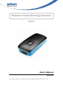
Wireless Pocket 2D Imager Scanner
- MS920 -
User's Manual
Version 2.0
© 2014 unitech Electronics Co., Ltd. All rights reserved. unitech is a registered trademark of unitech Electronics Co., Ltd.
Table of Contents
Chapter 1
Overview............................................................................................................ 1
Package Contents...................................................................................................1
Scanner Detail........................................................................................................2
Getting Start............................................................................................................3
Battery Charging.....................................................................................................3
Specification............................................................................................................4
Chapter 2
Bluetooth Function Setting................................................................................. 5
Pairing With PC/Notebook For The First Time........................................................5
Buffer Mode.............................................................................................................6
Switching Between HID and SPP Mode.................................................................7
Factory Default........................................................................................................8
Display F/W Version................................................................................................8
BT Un-pair...............................................................................................................8
iOS Keypad.............................................................................................................8
Inventory Space Left...............................................................................................8
Beep on Good Road (Toggle).................................................................................8
Beep on Connection Charge (Toggle).....................................................................8
Buffer Erasing.........................................................................................................9
Power Saving........................................................................................................10
BT Module Power Saving (Power off BT while no activities)................................10
HID Keyborad Character Delay............................................................................ 11
HID Keyborad Block Delay...................................................................................12
HID Keyborad Case..............................................................................................12
HID Keyborad Languages.....................................................................................13
Enter BT Pairing Code..........................................................................................14
Chapter 3
Symbologies..................................................................................................... 15
Disable all symbologies........................................................................................15
Codabar................................................................................................................15
Codablock.............................................................................................................19
Code 11.................................................................................................................21
Code 39................................................................................................................24
Code 93/ Code 93i................................................................................................30
Code 128 / GS1-128.............................................................................................32
DataMatrix.............................................................................................................37
EAN / UPC............................................................................................................40
GS1 DataBar (RSS)..............................................................................................48
Interleaved 2 of 5..................................................................................................52
Matrix 2 of 5..........................................................................................................55
MaxCode...............................................................................................................58
MicroPDF417........................................................................................................60
MSI Code..............................................................................................................61
PDF 417................................................................................................................64
Plessey Code........................................................................................................66
QR Code...............................................................................................................68
Standard 2 of 5.....................................................................................................71
Telepen.................................................................................................................75
Chapter 4
Operating Settings............................................................................................ 78
Pre-defined trigger modes....................................................................................78
Scanning / Triggering............................................................................................79
Data decoding security.........................................................................................88
Beeps / LEDs........................................................................................................91
Chapter 5
Data Transmission Settings.............................................................................. 96
ISCP......................................................................................................................96
Symbology identifier............................................................................................101
Preamble.............................................................................................................102
Postamble...........................................................................................................102
Inter-Character / message delay.........................................................................103
Data editing.........................................................................................................104
Chapter 6
Configuration Modes and Utilities....................................................................110
Get firmware version........................................................................................... 110
Get decode version............................................................................................. 110
Get asub-system versions.................................................................................. 110
Optical setup (using configuration bar codes)..................................................... 110
Transparent configuration mode......................................................................... 111
Appendix I
Worldwide Support..........................................................................................112
Overview
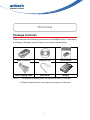
Package Contents
Please make sure the following contents are in the MS920 carton. If something
is missing or damaged, please contact your Unitech representative
MS912 scanner
Resource CD
Quick Guide
USB Charging Cable
Hand Strap
Battery
NOTE: 1. The scanner’s default power off (idle mode) time is 3 minutes.
2. Please charge scanner for at least 2 hours prior to initial use.
-1-
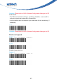
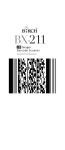
Scanner Detail
Getting Started
To scan a barcode, make sure the aiming beam crosses every bar and space
of the barcode.
-2-
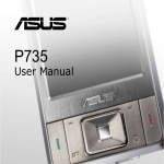
BATTERY CHARGING
1. Flip up the rubber cover to expose the mini USB port on the scanner.
2. Insert the mini USB connector into the port on the scanner and the standard
USB connector of the USB cable into a USB port on the host PC.
-3-
Specifications
Light source
Illumination: Highly visible white LED
Aiming : 617 nm red LED
Scan rate
240 scans/sec
Sensor
Linear CMOS sensor
Resolution
1D codes 0.1 mm (4 mils)
2D codes 0.167 mm (6.6 mils)
PCS
30%
Housing
Plastic (ABS)
Profile
SPP, HID
Working Hours
Over 13 hours (1 scan/3 seconds)
Charge Time
Fully charged in 4 hours
Coverage
330 ft(100m),class 1
Operating
Temp
0 to 50°C (32°F to 122°F)
Symbologies
1D: EAN/UPC, GS1 Databar (limited expanded & omnidirectional), Code 39, Code 128, UCC/EAN 128, ISBN, ISBT,
Interleaved/Matrix/ Industrial and Standard 2 of 5, Codabar,
Code 93/93i, Code 11, MSI, Plessey, Telepen, 2D: Data
Matrix, PDF417, Micro PDF 417, Codablock, Maxicode, QR,
AztecPostal: Australian Post, BPO, Canada Post, Dutch Post,
Japan Post, PostNet, Sweden Post
-4-
Chapter 2
Bluetooth Function Setting
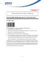
Pairing With PC/Notebook For The First Time
PC (HID mode)
Following steps are based on Microsoft Windows 7.
1. Use MS920 to scan barcode “HID”.
2. Open Devices and Printers by clicking the Start button , and then, on the
Start menu, clicking Devices and Printers.
3. Click Add a device, and then follow the instructions.
4. Click the Bluetooth enabled device (Unitech BT XXXXXX) you want to add
to your computer, and then click Next. If you don't see the device you want
to add, make sure the device is turned on and discoverable. If you just
turned on the device, it may take Windows several seconds to detect it.
For Bluetooth 2.0 (or lower) pairing, you have to use MS 920 to scan function
barcodes and numerical “Bluetooth Pincode” according to the direction shown
on the screen of the PC the MS 920 is pairing to during the pairing procedure.
Numerical barcodes and other function barcodes for Bluetooth Pincode entry
are listed on the reverse side of this sheet.
-5-
PC (SPP mode)
Following steps are based on Microsoft Windows 7.
1. Use MS920 t0 scan barcode “SPP”.
2. Open Devices and Printers by clicking the Start button
the Start menu, clicking Devices and Printers.
, and then, on
3. Click Add a device, and then click the Unitech AXXXXXX icon.
4. Open HyperTerminal, and select ingoing com part to make connection.
5. After one beep, start the scan then.
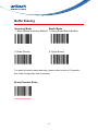
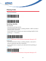
Buffer Mode
Auto Batch*
Inventory
No Buffer
No Buffer saved in the memory.
-6-
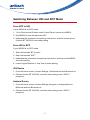
Switching Between HID and SPP Mode
From SPP to HID
If your MS920 is on SPP mode:
1. Go to Devices and Printers under Control Panel, remove the MS920.
2. Use MS920 to scan the barcode “HID”.
3. Undertake the procedure of searching new device, and then select device
(Unitech BT XXXXXX) and make pairing.
From HID to SPP
If your MS920 is on SPP mode:
1. Scan the barcode “BT Un-pair”.
2. Scan the barcode “SPP”.
3. Undertake the procedure of searching new device, and then select MS920
and make pairing.
4. Luanch HyperTerminal or Tera Term to make pairing.
iOS Device
1. From the Home screen, choose Settings > Bluetooth and turn Bluetooth on.
2. Choose Unitech BT XXXXXX, and then enter pairing code “0000” if
prompted.
Android Device
1. From the Home screen, choose Settings and goes to configurations for
Bluetooth and turn Bluetooth on.
2. Choose Unitech BT XXXXXX, and then enter pairing code “0000” if
prompted.
-7-
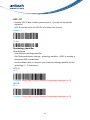
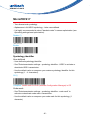
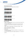
Factory Default
Display F/W Version
BT Un-pair
iOS Keypad
Press the trigger once will display
the keypad, press twice will be
disappeared.
Inventory Space Left
Beep on Good Road
(Toggle)
Check the memory size.
Beep on Connection
Charge (Toggle)
-8-
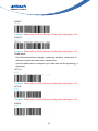
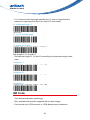
Buffer Erasing
Inventory Mode
Batch Mode
2. Scan (Erase)
2. Scan (Erase)
1. Scan (Erase Inventory Buffer) . 1. Scan (Erase Batch Buffer)
For detail information about barcodes, please refers to section 5. Appendix Bar Code Configuration And Commands.
Erase Previous Entry
Erase the last data.
-9-
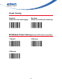
Power Saving
Enabled*
(Good for scan with trigger)
Disabled
(Good for continuous scanning)
BT Module Power Saving (Power off BT while no activities)
1 Minute*
3 Minutes
5 Minutes
- 10 -
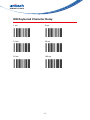
HID Keyborad Character Delay
1 ms
5 ms
10 ms
20 ms
50 ms
100 ms
- 11 -
HID Keyborad Block Delay
10 ms
50 ms
100 ms
500 ms
1 Sec.
3 Sec.
HID Keyborad Case
Auto Trace
To Lower
To Upper
- 12 -
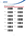
HID Keyborad Languages
US English
UK English
Swiss
Swedish
Norwegian
Italian
German
French
Danish
Partial ALT
Japanese
Spanish
ALT Mode
- 13 -
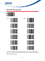
Enter BT Pairing Code
Enter
Abort
To scan "//7" label to enter code input mode, to scan "digit" as prompted on
host, to scan "$M" to finish input and exit input mode. To scan "$P" to abort
input and exit input mode.
- 14 -
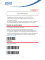
Chapter 3
Symbologies
- Symbology = bar code type or family (e.g. Code 39, UPC, EAN).
- Activate the symbologies you need and modify the settings for your
symbologies if required.
- To optimize performance, only activate symbologies you need !!! (deactivate
the Code 39 and EAN/UPC default symbologies if you don't need them.
Disable all symbologies
- Deactivates all the symbologies activated.
- Use the "not active" options to deactivate individual symbologies.
- Does not reset individual parameter settings for each symbology (when
you reactivate a symbology, you recover the parameter settings stored in
memory for that symbology when it was disabled - use reset factory defaults
to reset all the symbology parameters to their factory default settings).
Disable all symbologies
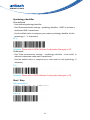
Codabar
- Numerical symbology
Disable (*)
Enable
- 15 -
Symbology identifier
User defined
- User defined symbology identifier.
- See "Data transmission settings - symbology identifier - UDSI" to activate or
deactivate UDSI transmission.
- Use the default value or compose your custom symbology identifier for this
symbology (1 - 4 characters)
B7 (*)
Compose: Please refer to SCM (Software Configuration Manager) in CD
Code mark
- See "Data transmission settings - symbology identifier - code mark" to
activate or deactivate code mark transmission.
- Use the default value or compose your code mark for this symbology (1
character).
D (*)
Compose: Please refer to SCM (Software Configuration Manager) in CD
Start / Stop
Not transmitted (*)
a, b, c, d
- 16 -
A, B, C, D
Check digit
check digit verification
- AIM has a recommended check character for Codabar
- Each Codabar data character (including Start/Stop) has a value assigned to
it:
0=0 1=1 2=2 3=3 4=4 5=5 6=6 7=7 8=8 9
= 9 - = 10 $ = 11 : = 12 / = 13 , = 14 + = 15 A = 16 B = 17 C = 18
D = 19
- The values are added and the check is calculated:
check = [(next multiple of 16) - (sum of assigned AIM values)]
Example
data characters:
A01234B
AIM values = 16 + 0 + 1 + 2 + 3 + 4 + 17:
next multiple of 16:
43
48
check = 48 - 43:
5
final message:
A012345B
Disable (*)
Enable
check digit transmissionr
- You can chose to transmit or not transmitted the check digit.
Disable (*)
- 17 -
Enable
Barcode length
- Use the L1 as minimum length option if you know the minimum length of the
codes in your application!!!
- To optimize decoding performance and increase security, select the same
length as the minimum length in your application (do not select a shorter
length!!).
Length = [start] + [barcode data] + [check digit] + [stop]
- Minimum length possible = 3 characters.
- If the codes in your application have fixed lengths, use barcode length mode
"L1, L2, and L3 as fixed lengths."
Length mode
- L1 = Codes with as many characters as specified by L1 and longer are read
(L2 and L3 are not used).
- L2 = Only codes that comply with the lengths specified by L1, L2, and L3 will
be read.
- L3 = Codes at least the length specified by L1 and no longer than the
maximum length specified by L2 are read (L3 is not used).
L1 as Minimal length (*)
L1, L2, L3 as fixed length
L1 as min, L2 as max
- 18 -
Set lengths 1, 2 and 3
- Set barcode length L1, L2 and L3 according to the barcode length mode
used.
Compose L1:
Compose L2:
Compose L3:
Codablock
- 2-dimensional alphanumerical symbology
Codablock A
Disable (*)
Enable
Symbology identifier
User defined
- User defined symbology identifier.
- See "Data transmission settings - symbology identifier - UDSI" to activate or
deactivate UDSI transmission.
- Use the default value or compose your custom symbology identifier for this
symbology (1 - 4 characters).
- 19 -
K1 (*)
Compose: Please refer to SCM (Software Configuration Manager) in CD
Code mark
- See "Data transmission settings - symbology identifier - code mark" to
activate or deactivate code mark transmission.
- Use the default value or compose your code mark for this symbology (1
character).
*(*)
Compose: Please refer to SCM (Software Configuration Manager) in CD
Codablock F
Disable (*)
Enable
Symbology identifier
User defined
- User defined symbology identifier.
- See "Data transmission settings - symbology identifier - UDSI" to activate or
deactivate UDSI transmission.
- Use the default value or compose your custom symbology identifier for this
symbology (1 - 4 characters)..
- 20 -
K1 (*)
Compose: Please refer to SCM (Software Configuration Manager) in CD
Code mark
- See "Data transmission settings - symbology identifier - code mark" to
activate or deactivate code mark transmission.
- Use the default value or compose your code mark for this symbology (1
character).
*(*)
Compose: Please refer to SCM (Software Configuration Manager) in CD
Code 11
- numerical symbology
Disable(*)
Enable
Symbology identifier
User defined
- User defined symbology identifier.
- See "Data transmission settings - symbology identifier - UDSI" to activate or
deactivate UDSI transmission.
- Use the default value or compose your custom symbology identifier for this
symbology (1 - 4 characters).
- 21 -
C1 (*)
Compose: Please refer to SCM (Software Configuration Manager) in CD
Code mark
- See "Data transmission settings - symbology identifier - code mark" to
activate or deactivate code mark transmission.
- Use the default value or compose your code mark for this symbology (1
character).
*(*)
Compose: Please refer to SCM (Software Configuration Manager) in CD
Check digits
1 digit (*)
2 digits
Transmitted (*)
Not transmitted
- 22 -
Barcode Length
- Use the L1 as minimum length option if you know the minimum length of the
codes in your application!!!
- To optimize decoding performance and increase security, select the same
length as the minimum length in your application (do not select a shorter
length!!).
Length mode
- L1 = Codes with as many characters as specified by L1 and longer are read
(L2 and L3 are not used).
- L2 = Only codes that comply with the lengths specified by L1, L2, and L3 will
be read.
- L3 = Codes at least the length specified by L1 and no longer than the
maximum length specified by L2 are read (L3 is not used).
L1 as Minimal length (*)
L1, L2, L3 as fixed length
L1 as min, L2 as max
Set lengths 1, 2 and 3
- Set barcode length L1, L2 and L3 according to the barcode length mode
used.
Compose L1:
- 23 -
Compose L2:
Compose L3:
Code 39
- Alphanumeric symbology.
- Letter case not defined - transmitted in upper case.
- Format: standard 43 characters (default) or full ASCII (see "format" for lists).
Disable
Enamle(*)
Symbology identifier
User defined
- User defined symbology identifier.
- See "Data transmission settings - symbology identifier - UDSI" to activate or
deactivate UDSI transmission.
- Use the default value or compose your custom symbology identifier for this
symbology (1 - 4 characters).
B1 (*)
Compose: Please refer to SCM (Software Configuration Manager) in CD
- 24 -
Code mark
- See "Data transmission settings - symbology identifier - code mark" to
activate or deactivate code mark transmission.
- Use the default value or compose your code mark for this symbology (1
character).
*(*)
Compose: Please refer to SCM (Software Configuration Manager) in CD
Format
Standard 43 characters (*)
Full ASCII (extended)
Start / Stop
Not transmitted (*)
Transmitted
accepted characters
'*' only (*)
- 25 -
'$' only
'$' only *'
Check digit
check digi verification
Disable (*)
Modulo 43
French CIP
Italian CPI
check digi transmission
- You can chose to transmit or not transmitted the check digit.
Disable (*)
- 26 -
Enable
Barcode length
- Use the L1 as minimum length option if you know the minimum length of the
codes in your application!!!
- To optimize decoding performance and increase security, select the same
length as the minimum length in your application (do not select a shorter
length!!).
Length = [start] + [barcode data] + [check digit] + [stop]
- Minimum length possible = 3
Length mode
- L1 = Codes with as many characters as specified by L1 and longer are read
(L2 and L3 are not used).
- L2 = Only codes that comply with the lengths specified by L1, L2, and L3 will
be read.
- L3 = Codes at least the length specified by L1 and no longer than the
maximum length specified by L2 are read (L3 is not used).
L1 as Minimal length (*)
L1, L2, L3 as fixed length
L1 as Min, L2 and L3
- 27 -
Set lengths 1, 2 and 3
- Set barcode length L1, L2 and L3 according to the barcode length mode
used.
Compose L1:
Compose L2:
Compose L3:
Reading range
- Applies a special algorithm for long-distance reading (default setting).
- Use the "normal" setting if distance reading is not required.
Extended (*)
Normal
Reading tolerance
- Sets the tolerance level for reading hard to read bar codes.
- High = most permissive (reads codes of variable quality).
- Low = least permissive (only reads high quality codes that meet official Code
39 standards)
- Quiet zone verification (space before and after bar code to ensure correct
decoding).
- 28 -
High (*)
Medium
Low
Unconventional Code 39
- Used for decoding unconventional Code 39 such as:
- very large inter-character
- large ratio between narrow and wide elements
Disable (*)
Enable
Special keys interpretation
- Special keyboard keys such as [Enter] and [Tab] (see list below) can be
interpreted and transmitted by using dual-character combinations.
- This function is also compatible with the Code 39 full ASCII format.
Disable (*)
- 29 -
Enable
Code 93/ Code 93i
- Code 93
Alphanumeric full ASCII symbology - letter case defined.
- Code 93i (encompasses and extends Code 93)
Alphanumeric, full and extended ASCII, all Unicode characters, etc
Disable
Enable (*)
Symbology indentifier
User Defined
- User defined symbology identifier.
- See "Data transmission settings - symbology identifier - UDSI" to activate or
deactivate UDSI transmission.
- Use the default value or compose your custom symbology identifier for this
symbology (1 - 4 characters).
B6 (*)
Compose: Please refer to SCM (Software Configuration Manager) in CD
- 30 -
Code mark
- See "Data transmission settings - symbology identifier - code mark" to
activate or deactivate code mark transmission.
- Use the default value or compose your code mark for this symbology (1
character).
D (*)
Compose: Please refer to SCM (Software Configuration Manager) in CD
Barcode length
- Use the L1 as minimum length option if you know the minimum length of the
codes in your application!!!
- To optimize decoding performance and increase security, select the same
length as the minimum length in your application (do not select a shorter
length!!).
Length = [barcode data]
- Minimum length possible = 1 characters.
Length mode
- L1 = Codes with as many characters as specified by L1 and longer are read
(L2 and L3 are not used).
- L2 = Only codes that comply with the lengths specified by L1, L2, and L3 will
be read.
- L3 = Codes at least the length specified by L1 and no longer than the
maximum length specified by L2 are read (L3 is not used).
L1 as Minimal length (*)
L1, L2, L3 as fixed length
- 31 -
L1 as min, L2 as max
Set lengths 1, 2 and 3
- Set barcode length L1, L2 and L3 according to the barcode length mode
used.
Compose L1:
Compose L2:
Compose L3:
Code 128 / GS1-128
- Alphanumeric full ASCII symbology - letter case defined.
- "GS1-128" = Code 128 with the FNC1 character in the first position.
Code 128 enable (*)
Code 128 disable
GS1 - 128 enable (*)
- 32 -
GS1 - 128 disable
Symbology identifier
User defined
- User defined symbology identifier.
- See "Data transmission settings - symbology identifier - UDSI" to activate or
deactivate UDSI transmission.
- Use the default value or compose your custom symbology identifier for this
symbology (1 - 4 characters).
Code 128
B3 (*)
Compose: Please refer to SCM (Software Configuration Manager) in CD
GS1 128
C9 (*)
Compose: Please refer to SCM (Software Configuration Manager) in CD
Code mark
- See "Data transmission settings - symbology identifier - code mark" to
activate or deactivate code mark transmission.
- Use the default value or compose your code mark for this symbology (1
character).
Code 128
D (*)
Compose: Please refer to SCM (Software Configuration Manager) in CD
- 33 -
GS1 128
D (*)
Compose: Please refer to SCM (Software Configuration Manager) in CD
GS1 - 128 identifier
- The ]C1 AIM identifier for GS1-128 is automatically added by default in front
of GS1-128 bar codes.
Enable (*)
Disable
Barcode length
- Use the L1 as minimum length option if you know the minimum length of the
codes in your application!!!
- To optimize decoding performance and increase security, select the same
length as the minimum length in your application (do not select a shorter
length!!).
Length = [barcode data]
- Minimum length possible = 1 characters.
Length mode
- L1 = Codes with as many characters as specified by L1 and longer are read
(L2 and L3 are not used).
- L2 = Only codes that comply with the lengths specified by L1, L2, and L3 will
be read.
- L3 = Codes at least the length specified by L1 and no longer than the
maximum length specified by L2 are read (L3 is not used).
- 34 -
L1 as Minimal length (*)
L1, L2, L3 as fixed length
L1 as min, L2 as max
Set lengths 1, 2 and 3
- Set barcode length L1, L2 and L3 according to the barcode length mode
used..
Compose L1:
Compose L2:
Compose L3:
Reading tolerance
- Sets the tolerance level for reading hard to read bar codes.
- High = most permissive (reads codes of variable quality).
- Low = least permissive (only reads high quality codes that meet official Code
39 standards)
- Quiet zone verification (space before and after bar code to ensure correct
decoding).
- 35 -
High (*)
Medium
Low
Reading range
- Applies a special algorithm for long-distance reading (default setting).
- Use the "normal" setting if distance reading is not required.
Extended (*)
Normal
ISBT 128
- International Society of Blood Transfusion
- Activating ISBT 128 deactivates Code 128 / GS1-128 (to avoid confusion with
Code 128 / GS1-128).
- You can re-activate Code 128 or GS1-128 by using the corresponding setup
command if desired.
- IMPORTANT:
- Codes are not concatenated by default (default transmission setting is
"single codes only").
- You must select one of the "concatenated codes" transmission options to
send concatenated codes (see "transmit" section).
- 36 -
Disable (*)
Transmit
Disable (*)
Only transmit concatenated codes
Transmit concatenated codes or single codes
Concatenate
Disable (*)
Enable
DataMatrix
- Two-dimensional symbology.
- Only available with models equipped with an area imager.
- Can encode up to approximately 2000 characters.
- Negative image DataMatrix supported.
- Mirror image DataMatrix not supported.
- 37 -
Disable
Enamle (*)
Symbology identifier
User defined
- User defined symbology identifier.
- See "Data transmission settings - symbology identifier - UDSI" to activate or
deactivate UDSI transmission.
- Use the default value or compose your custom symbology identifier for this
symbology (1 - 4 characters).
D0 (*)
Compose: Please refer to SCM (Software Configuration Manager) in CD
Code mark
- See "Data transmission settings - symbology identifier - code mark" to
activate or deactivate code mark transmission.
- Use the default value or compose your code mark for this symbology (1
character).
* (*)
Compose: Please refer to SCM (Software Configuration Manager) in CD
- 38 -
Mirrored labels activation
- When enabled mirrored labels can be read as well as normal labels.
- When disabled only normal labels can be read.
Disable (*)
Enable
Structured append
Disable (*)
Enable
Header transmission
Disable (*)
Enable
- 39 -
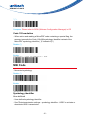
EAN / UPC
- Numerical symbology.
UPC - A enable (*)
UPC - A disable
UPC - E enable (*)
UPC - E disable
EAN - 8 enable (*)
EAN - 8 disable
EAN - 13 enable (*)
EAN - 13 disable
- 40 -
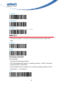
UPC - E1
- Irregular UPC-E with number system equal to 1 (usually the first printed
character).
- UPC-E must be active for UPC-E1 to be taken into account.
Disable (*)
Enable
Symbology identifier
User defined
- User defined symbology identifier.
- See "Data transmission settings - symbology identifier - UDSI" to activate or
deactivate UDSI transmission.
- Use the default value or compose your custom symbology identifier for this
symbology (1 - 4 characters).
UPC-A
A0 (*)
Compose: Please refer to SCM (Software Configuration Manager) in CD
UPC-E
E0 (*)
Compose: Please refer to SCM (Software Configuration Manager) in CD
- 41 -
EAN-8
FF (*)
Compose: Please refer to SCM (Software Configuration Manager) in CD
EAN-13
F (*)
Compose: Please refer to SCM (Software Configuration Manager) in CD
Code mark
- See "Data transmission settings - symbology identifier - code mark" to
activate or deactivate code mark transmission.
- Use the default value or compose your code mark for this symbology (1
character).
UPC-A
A (*)
Compose: Please refer to SCM (Software Configuration Manager) in CD
UPC-E
E (*)
Compose: Please refer to SCM (Software Configuration Manager) in CD
EAN-8
N (*)
- 42 -
Compose: Please refer to SCM (Software Configuration Manager) in CD
EAN-13
F (*)
Compose: Please refer to SCM (Software Configuration Manager) in CD
Add - on digits
not required but transmitted if read (*)
required and transmitted
add-on 2
Disable (*)
Enable
add-on 5
Disable (*)
Enable
- 43 -
security level
10 (*)
Compose: Please refer to SCM (Software Configuration Manager) in CD
Check digit transmission
[leading character] [number system] [data] [check digit]
UPC-A
Enable (*)
Disable
UPC-E
Enable (*)
Disable
EAN-8
Enable (*)
Disable
- 44 -
EAN-13
Enable (*)
Disable
UPC number system
[leading character] [number system] [data] [check digit]
UPC-A
Enable (*)
Disable
UPC-E
Enable (*)
Disable
- 45 -
Re-encoding UPC-A, UPC-E, EAN-8
[leading character] [number system] [data] [check digit]
- Converts decoded data to other code formats.
- Transmission only takes into account the parameters available for the target
bar code format.
- Regular UPC-A has a transmitted number system equal to 0.
- To transmit the additional leading character (country code), select the "UPC-A
transmitted as EAN-13" option.
UPC-A, UPC-E, EAN-8 - UPC-A transmitted as EAN-13 (*)
UPC-A, UPC-E, EAN-8 - UPC-A transmitted as UPC-A
UPC-A, UPC-E, EAN-8 - UPC-E transmitted as UPC-E (*)
UPC-A, UPC-E, EAN-8 - UPC-E transmitted as UPC-A
UPC-A, UPC-E, EAN-8 - EAN-8 transmitted as EAN-8 (*)
UPC-A, UPC-E, EAN-8 - EAN-8 transmitted as EAN-13
- 46 -
ISBN
- International Standard Book Number
- EAN-13 code, the first 3 characters "978" or "979" (except for "9790")
are ignored and the checksum (0..9, "X") is calculated on the remaining
characters.
Disable (*)
Enable
ISMN
- International Standard Music Number
- EAN-13 code starting with "9790", the first 3 characters "979" are ignored and
the first "0" is converted to "M"
Disable (*)
Enable
ISSN
- International Standard Serial Number
- EAN-13 code, the first 3 characters "977" are ignored and the ISBN
checksum (0..9, "X") is calculated on the remaining characters.
Disable (*)
- 47 -
Enable
Reading range
- Applies a special algorithm for long-distance reading (default setting).
- Use the "normal" setting if distance reading is not required.
Normal
Extended (*)
GS1 DataBar (RSS)
- Also known as Reduced Space Symbology (RSS).
Omni-directional
- Numerical symbology.
- Reads the following types of GS1 DataBar:
GS1 DataBar Omni-Directional
GS1 DataBar Truncated
GS1 DataBar Stacked
GS1 DataBar Stacked Omni-Directional
Enable
- 48 -
Disable (*)
Symbology identifier
User defined
- User defined symbology identifier.
- See "Data transmission settings - symbology identifier - UDSI" to activate or
deactivate UDSI transmission.
- Use the default value or compose your custom symbology identifier for this
symbology (1 - 4 characters).
C3 (*)
Compose: Please refer to SCM (Software Configuration Manager) in CD
Code mark
- See "Data transmission settings - symbology identifier - code mark" to
activate or deactivate code mark transmission.
- Use the default value or compose your code mark for this symbology (1
character).
* (*)
Compose: Please refer to SCM (Software Configuration Manager) in CD
Limited
- Numerical symbology.
- Does not read stacked version.
Enable
- 49 -
Disable (*)
Symbology identifier
User defined
- User defined symbology identifier.
- See "Data transmission settings - symbology identifier - UDSI" to activate or
deactivate UDSI transmission.
- Use the default value or compose your custom symbology identifier for this
symbology (1 - 4 characters).
C4 (*)
Compose: Please refer to SCM (Software Configuration Manager) in CD
Code mark
- See "Data transmission settings - symbology identifier - code mark" to
activate or deactivate code mark transmission.
- Use the default value or compose your code mark for this symbology (1
character).
* (*)
Compose: Please refer to SCM (Software Configuration Manager) in CD
Expanded
- Alphanumerical symbology.
- Reads the following types of GS1 DataBar Expanded:
GS1 DataBar Expanded
GS1 DataBar Expanded Stacked
- 50 -
Enable
Disable (*)
Symbology identifier
User defined
- User defined symbology identifier.
- See "Data transmission settings - symbology identifier - UDSI" to activate or
deactivate UDSI transmission.
- Use the default value or compose your custom symbology identifier for this
symbology (1 - 4 characters).
C5 (*)
Compose: Please refer to SCM (Software Configuration Manager) in CD
Code mark
- See "Data transmission settings - symbology identifier - code mark" to
activate or deactivate code mark transmission.
- Use the default value or compose your code mark for this symbology (1
character).
* (*)
Compose: Please refer to SCM (Software Configuration Manager) in CD
- 51 -
Interleaved 2 of 5
- Numerical symbology.
- For GTIN compatibility set barcode length to one fixed length of 14
characters.
Disable (*)
Enable
Symbology identifier
User defined
- User defined symbology identifier.
- See "Data transmission settings - symbology identifier - UDSI" to activate or
deactivate UDSI transmission.
- Use the default value or compose your custom symbology identifier for this
symbology (1 - 4 characters).
B2 (*)
Compose: Please refer to SCM (Software Configuration Manager) in CD
Code mark
- See "Data transmission settings - symbology identifier - code mark" to
activate or deactivate code mark transmission.
- Use the default value or compose your code mark for this symbology (1
character).
I (*)
- 52 -
Compose: Please refer to SCM (Software Configuration Manager) in CD
Check digit
- Especially recommended for variable length Interleaved 2 of 5 and if
"consecutive same read data validation" (data decoding security parameters)
is not activated.
Check digit verification
Disable (*)
Modulo 10
Check digit transmission
Disable (*)
Enable
Barcode length
- Use the L1 as minimum length option if you know the minimum length of the
codes in your application!!!
- To optimize decoding performance and increase security, select the same
length as the minimum length in your application (do not select a shorter
length!!).
= [barcode data] + [check digit]
- Recommended minimum length = 4 characters.
- Interleaved 2 of 5 always encodes an even number of characters.
- For codes with an odd number of characters, you can add a last character
printed as 5 narrow bars (not transmitted).
- 53 -
- For GTIN compatibility set barcode length to one fixed length of 14 characters
- compose 1 or 2 or 3 fixed lengths provides the best performance and security
if the codes in your application have fixed lengths
Length mode
- L1 = Codes with as many characters as specified by L1 and longer are read
(L2 and L3 are not used).
- L2 = Only codes that comply with the lengths specified by L1, L2, and L3 will
be read.
- L3 = Codes at least the length specified by L1 and no longer than the
maximum length specified by L2 are read (L3 is not used).
L1 as Minimal length (*)
L1, L2, L3 as fixed length
L1 as min, L2 as max
Set length L1, L2 and L3
- Set barcode length L1, L2 and L3 according to the barcode length mode
used.
Compose L1:
Compose L2:
- 54 -
Compose L3:
Reading tolerance
- Sets the tolerance level for reading hard to read bar codes.
- High = most permissive (reads codes of variable quality).
- Low = least permissive (only reads high quality codes that meet official Code
39 standards)
- Quiet zone verification (space before and after bar code to ensure correct
decoding).
High (*)
Medium
Low
Matrix 2 of 5
- Numerical symbology.
Disable (*)
Enable
- 55 -
Symbology identifier
User defined
- User defined symbology identifier.
- See "Data transmission settings - symbology identifier - UDSI" to activate or
deactivate UDSI transmission.
- Use the default value or compose your custom symbology identifier for this
symbology (1 - 4 characters).
B4 (*)
Compose: Please refer to SCM (Software Configuration Manager) in CD
Code mark
- See "Data transmission settings - symbology identifier - code mark" to
activate or deactivate code mark transmission.
- Use the default value or compose your code mark for this symbology (1
character).
D (*)
Compose: Please refer to SCM (Software Configuration Manager) in CD
Matrix stop/start char
Regular (*)
- Start/stop characters and checksum not transmitted.
Regular (*)
- 56 -
ChinaPost
- Specific start/stop characters (not transmitted) and checksum (transmitted).
ChinaPost
Barcode length
- Use the L1 as minimum length option if you know the minimum length of the
codes in your application!!!
- To optimize decoding performance and increase security, select the same
length as the minimum length in your application (do not select a shorter
length!!).
Length = [barcode data]
- Minimum length possible = 3 characters.
Length mode
- L1 = Codes with as many characters as specified by L1 and longer are read
(L2 and L3 are not used).
- L2 = Only codes that comply with the lengths specified by L1, L2, and L3 will
be read.
- L3 = Codes at least the length specified by L1 and no longer than the
maximum length specified by L2 are read (L3 is not used).
L1 as Minimal length (*)
L1, L2, L3 as fixed length
L1 as min, L2 as max
- 57 -
Set length L1, L2 and L3
- Set barcode length L1, L2 and L3 according to the barcode length mode
used.
Compose L1:
Compose L2:
Compose L3:
MaxCode
- Two-dimensional alphanumerical symbology used by UPS.
- Only available with models equipped with an area imager.
Disable (*)
Enable
Symbology identifier
User defined
- User defined symbology identifier.
- See "Data transmission settings - symbology identifier - UDSI" to activate or
deactivate UDSI transmission.
- Use the default value or compose your custom symbology identifier for this
symbology (1 - 4 characters).
- 58 -
D2 (*)
Compose: Please refer to SCM (Software Configuration Manager) in CD
Code mark
- See "Data transmission settings - symbology identifier - code mark" to
activate or deactivate code mark transmission.
- Use the default value or compose your code mark for this symbology (1
character).
* (*)
Compose: Please refer to SCM (Software Configuration Manager) in CD
Mode 0
- This mode is obsolete.
- We do not recommend using this mode.
Disable (*)
Enable
Header
regular (AIM) (*)
Extended
- 59 -
MicroPDF417
- Two-dimensional symbology.
- Alphanumeric full ASCII symbology - letter case defined.
- It is highly recommended to select "stacked codes" in sensor optimization (see
Operating settings/read optimization).
Disable (*)
Enable
Symbology identifier
User defined
- User defined symbology identifier.
- See "Data transmission settings - symbology identifier - UDSI" to activate or
deactivate UDSI transmission.
- Use the default value or compose your custom symbology identifier for this
symbology (1 - 4 characters).
C8 (*)
Compose: Please refer to SCM (Software Configuration Manager) in CD
Code mark
- See "Data transmission settings - symbology identifier - code mark" to
activate or deactivate code mark transmission.
- Use the default value or compose your code mark for this symbology (1
character).
- 60 -
* (*)
Compose: Please refer to SCM (Software Configuration Manager) in CD
Code 128 emulation
- When active and reading a MicroPDF code containing a special flag, the
scanner transmits the Code 128 AIM symbology identifier instead of the
MicroPDF symbology identifier ( ]C instead of ]L )
Disable (*)
Enable
MSI Code
- Numerical symbology.
Disable (*)
Enable
Symbology identifier
User defined
- User defined symbology identifier.
- See "Data transmission settings - symbology identifier - UDSI" to activate or
deactivate UDSI transmission.
- 61 -
- Use the default value or compose your custom symbology identifier for this
symbology (1 - 4 characters).
B8 (*)
Compose: Please refer to SCM (Software Configuration Manager) in CD
Code mark
- See "Data transmission settings - symbology identifier - code mark" to
activate or deactivate code mark transmission.
- Use the default value or compose your code mark for this symbology (1
character).
D (*)
Compose: Please refer to SCM (Software Configuration Manager) in CD
Check digit
Check digit verification
Modulo 10 (*)
Double Modulo 10
Check digit transmission
- You can chose to transmit or not transmitted the check digit.
Enable (*)
- 62 -
Disable
Barcode length
- Use the L1 as minimum length option if you know the minimum length of the
codes in your application!!!
- To optimize decoding performance and increase security, select the same
length as the minimum length in your application (do not select a shorter
length!!).
Length = [barcode data] + [check digit]
- Minimum length possible = 2 characters.
Length mode
- L1 = Codes with as many characters as specified by L1 and longer are read
(L2 and L3 are not used).
- L2 = Only codes that comply with the lengths specified by L1, L2, and L3 will
be read.
-
L3 = Codes at least the length specified by L1 and no longer than the
maximum length specified by L2 are read (L3 is not used).
L1 as Minimal length (*)
L1, L2, L3 as fixed length
L1 as min, L2 as max
Set length L1, L2 and L3
-
Set barcode length L1, L2 and L3 according to the barcode length mode
used.
- 63 -
Compose L1:
Compose L2:
Compose L3:
PDF 417
- Set barcode length L1, L2 and L3 according to the barcode length mode
used.
Enable (*)
Disable
Symbology identifier
User defined
- User defined symbology identifier.
- See "Data transmission settings - symbology identifier - UDSI" to activate or
deactivate UDSI transmission.
- Use the default value or compose your custom symbology identifier for this
symbology (1 - 4 characters).
C7 (*)
- 64 -
Compose: Please refer to SCM (Software Configuration Manager) in CD
Code mark
- See "Data transmission settings - symbology identifier - code mark" to
activate or deactivate code mark transmission.
- Use the default value or compose your code mark for this symbology (1
character).
* (*)
Compose: Please refer to SCM (Software Configuration Manager) in CD
Structured append
Disable (*)
Enable
Header transmission
Disable (*)
Enable
- 65 -
Plessey Code
- Numerical symbology.
Disable (*)
Enable
Symbology identifier
User defined
- User defined symbology identifier.
- See "Data transmission settings - symbology identifier - UDSI" to activate or
deactivate UDSI transmission.
- Use the default value or compose your custom symbology identifier for this
symbology (1 - 4 characters).
C2 (*)
Compose: Please refer to SCM (Software Configuration Manager) in CD
Code mark
- See "Data transmission settings - symbology identifier - code mark" to
activate or deactivate code mark transmission.
- Use the default value or compose your code mark for this symbology (1
character).
D (*)
Compose: Please refer to SCM (Software Configuration Manager) in CD
- 66 -
Check digit transmission
[leading character] [number system] [data] [check digit]
Disable (*)
Enable
Unconventional stop
Disable (*)
Enable
Barcode length
- Use the L1 as minimum length option if you know the minimum length of the
codes in your application!!!
- To optimize decoding performance and increase security, select the same
length as the minimum length in your application (do not select a shorter
length!!).
Length = [start] + [barcode data] + [2-character check digit] + [stop]
- Minimum length possible = 5 characters.
Maximum length possible = 25 characters.
Length mode
- L1 = Codes with as many characters as specified by L1 and longer are read
(L2 and L3 are not used).
- L2 = Only codes that comply with the lengths specified by L1, L2, and L3 will
be read.
- 67 -
- L3 = Codes at least the length specified by L1 and no longer than the
maximum length specified by L2 are read (L3 is not used).
L1 as Minimal length (*)
L1, L2, L3 as fixed length
L1 as min, L2 as max
Set length L1, L2 and L3
- Set barcode length L1, L2 and L3 according to the barcode length mode
used.
Compose L1:
Compose L2:
Compose L3:
QR Code
- Two-dimensional matrix symbology.
- Only available with models equipped with an area imager.
- Can encode up to 2509 numeric or 1520 alphanumeric characters.
- 68 -
- Offers three levels of error detection.
- Activating QR Code activates Model 2. Use the Model 1Control activation if
you are using Model 1 (not supported by all scanners).
- Negative image QR Code not supported.
Disable (*)
Enable
Model 1 control
- Enables the decoding of Model 1 QR codes.
Disable (*)
Enable
Inverse video
- Normal = used for decoding black bar codes printed on white background.
- Inverse = used for decoding white bar codes printed on black background.
- Automatic = used to decode both types of bar codes
Normal (*)
Inverse
- 69 -
Automatic
MicroQR activation
- Micro QR is a small QR code with only one pattern.
Disable (*)
Enable
Symbology identifier
User defined
- User defined symbology identifier.
- See "Data transmission settings - symbology identifier - UDSI" to activate or
deactivate UDSI transmission.
- Use the default value or compose your custom symbology identifier for this
symbology (1 - 4 characters).
D1 (*)
Compose: Please refer to SCM (Software Configuration Manager) in CD
Code mark
- See "Data transmission settings - symbology identifier - code mark" to
activate or deactivate code mark transmission.
- Use the default value or compose your code mark for this symbology (1
character).
- 70 -
* (*)
Compose: Please refer to SCM (Software Configuration Manager) in CD
Structured append
Disable (*)
Enable
Header transmission
Disable (*)
Enable
Standard 2 of 5
- Numerical symbology.
- Default format = Identicon (6 start/stop bars).
- Also referred to as "Straight 2 of 5" and "Industrial 2 of 5."
Disable (*)
- 71 -
Enable
Symbology identifier
User defined
- User defined symbology identifier.
- See "Data transmission settings - symbology identifier - UDSI" to activate or
deactivate UDSI transmission.
- Use the default value or compose your custom symbology identifier for this
symbology (1 - 4 characters).
B5 (*)
Compose: Please refer to SCM (Software Configuration Manager) in CD
Code mark
- See "Data transmission settings - symbology identifier - code mark" to
activate or deactivate code mark transmission.
- Use the default value or compose your code mark for this symbology (1
character).
D (*)
Compose: Please refer to SCM (Software Configuration Manager) in CD
Format
Identicon (*)
- 72 -
Computer Identics
Check digit
Check digit verification
Disable (*)
Modulo 10
Check digit transmission
- You can chose to transmit or not transmitted the check digit.
Disable (*)
Enable
Barcode length
- Use the L1 as minimum length option if you know the minimum length of the
codes in your application!!!
- To optimize decoding performance and increase security, select the same
length as the minimum length in your application (do not select a shorter
length!!).
Length = [barcode data] + [check digit]
- Minimum length possible = 3
Length mode
- L1 = Codes with as many characters as specified by L1 and longer are read
- 73 -
(L2 and L3 are not used).
- L2 = Only codes that comply with the lengths specified by L1, L2, and L3 will
be read.
- L3 = Codes at least the length specified by L1 and no longer than the
maximum length specified by L2 are read (L3 is not used).
L1 as Minimal length (*)
L1, L2, L3 as fixed length
L1 as min, L2 as max
Set length L1, L2 and L3
- Set barcode length L1, L2 and L3 according to the barcode length mode
used.
Compose L1:
Compose L2:
Compose L3:
- 74 -
Telepen
- Alphanumeric full ASCII symbology - letter case defined.
- Default format = ASCII.
Disable (*)
Enable
Symbology identifier
User defined
- User defined symbology identifier.
- See "Data transmission settings - symbology identifier - UDSI" to activate or
deactivate UDSI transmission.
- Use the default value or compose your custom symbology identifier for this
symbology (1 - 4 characters).
C6 (*)
Compose: Please refer to SCM (Software Configuration Manager) in CD
Code mark
- See "Data transmission settings - symbology identifier - code mark" to
activate or deactivate code mark transmission.
- Use the default value or compose your code mark for this symbology (1
character).
* (*)
Compose: Please refer to SCM (Software Configuration Manager) in CD
- 75 -
Format
ASCII (*)
Numeric
Barcode length
- Use the L1 as minimum length option if you know the minimum length of the
codes in your application!!!
- To optimize decoding performance and increase security, select the same
length as the minimum length in your application (do not select a shorter
length!!).
Length = [barcode data]
- Minimum length possible = 1 characters.s.
Length mode
- L1 = Codes with as many characters as specified by L1 and longer are read
(L2 and L3 are not used).
- L2 = Only codes that comply with the lengths specified by L1, L2, and L3 will
be read.
- L3 = Codes at least the length specified by L1 and no longer than the
maximum length specified by L2 are read (L3 is not used).
L1 as Minimal length (*)
L1, L2, L3 as fixed length
- 76 -
L1 as min, L2 as max
Set length L1, L2 and L3
- Set barcode length L1, L2 and L3 according to the barcode length mode
used.
Compose L1:
Compose L2:
Compose L3:
- 77 -
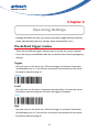
Chapter 4
Operating Settings
- Settings that affect the way your product operates (trigger settings, flashing
mode, data decoding security settings, beep characteristics, etc.).
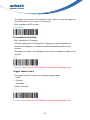
Pre-defined trigger modes
- These are pre-defined trigger settings used to quickly set up your scanner.
- If you are using a pre-defined mode, do not set the other Scanning/triggering
settings.
Toggle
- One pull turns on the aimer only. When the trigger is released, illumination
and decoding turn on. If no decode, second pull and release turn the aimer,
illumination and decoding off.
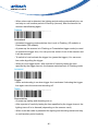
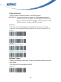
Toggle
Level
- One pull turns on the aimer, illumination and decoding. If not decode, aimer,
illumination and decoding turn off when the trigger is released.
Level
Aim
- One pull turns on the aimer only. When the trigger is released, illumination
and decoding turn on. If no decode, second pull and release turn the aimer,
illumination and decoding off.
- 78 -
Aim
Scanning / Triggering
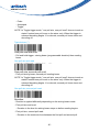
Triggering modes
Continuous
- At power up the lighting and decoding are on all the time. The trigger is not
used.
Continuous
Level (*)
- Lighting and decoding are on when the trigger line is activated (trigger
pressed) and off when the trigger line is deactivated (trigger released).
Level (*)
Pulse
- Lighting and decoding are on when the trigger line is activated (trigger
pressed) and stay on until a period of inactivity lasting the time specified by
the trigger timeout.
- After the timeout lighting and decoding are turned off.
Pulse
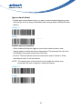
Flashing
- At power up the lighting and decoding are on (no need to activate the trigger
line) and after a period of inactivity lasting the time specified by the trigger
timeout, the scanner starts flashing, checking for a bar code to be read.
- 79 -
- When a bar code is detected, the lighting and decoding automatically turn on
and stay on until another period of inactivity (timeout), after the timeout the
scanner starts flashing again.
Flashing
Autostand
- Autostand triggering mode switches from Level to Flashing (1D models) or
Presentation (2D models).
- At power up the scanner is in Flashing or Presentation trigger mode (no need
to activate the trigger line). You can put a bar code in front of the scanner and
it will be scanned.
- To switch to Level activate the trigger line (press the trigger). You can scan
bar codes by pulling the trigger.
- When in Level trigger mode, after a period of inactivity lasting the time
specified by the trigger timeout, the scanner switches back to Flashing mode.
Autostand
Toggle
- Aimer and decoding is on when trigger line is activated. Activating the trigger
line again turns the aimer and decoding off.
Toggle
Presentation
- At power up lighting and decoding are on.
- After a period of inactivity lasting the time specified by the trigger timeout, the
lighting turns off or is dimmed (depending on the scanner used).
- When a new bar code is presented the lighting and decoding restart and stay
on until another period inactivity.
- 80 -
- The trigger can be used in Presentation mode - when you pull the trigger the
scanner functions as if it were in Level mode.
- Only available with 2D models.
Presentation
Presentation threshold
- Only available on 2D models.
- Use this setting when in Presentation Triggering mode to regulate how
sensitive the imager is to movement which automatically wakes up the
scanner.
- The higher the value = the stronger the movement is needed to wake up the
scanner.
50 (*)
Compose: Please refer to SCM (Software Configuration Manager) in CD
Trigger timeout (sec)
- The trigger timeout is used in the following trigger modes:
- Pulse
- Flashing
- Autostand
- Value in seconds
2 (*)
Compose: Please refer to SCM (Software Configuration Manager) in CD
- 81 -
Trigger activation
- Used to enable or disable hardware or emulated triggers.
IMPORTANT: You cannot activate the trigger line if the hardware trigger is
disabled. If you are using level or pulse trigger modes, the only
way to re-activate the hardware trigger is by using online set up
(ISCP terminal) or sending an ISCP command.
Disabled
- Hardware and emulated triggers are disabled. The only way to turn the
imager on is by sending a decode on/decode off control command (20, 40).
Disabled
Hardware trigger enabled
Emulated trigger enabled
Hardware and emulated trigger
Software Trigger
- Reading controlled by "start read" / "stop read" characters received from the
host system.
- This option is NOT compatible with ISCP.
Disable (*)
- 82 -
Enabled
- Start read character default = STX
- Stop read character default = ETX
- This option is NOT compatible with ISCP.
Enable
start character [STX] (*)
Compose start character
- Use different characters for "start read" and "stop read."
- This option is NOT compatible with ISCP.
Compose start character
stop character [ETX] (*)
Compose stop character
- Use different characters for "start read" and "stop read."
- This option is NOT compatible with ISCP.
Compose stop character
- 83 -
Turn off after good read
- When active, the scan engine stops the reading session after a successful
decoding.
- Turn off after good read is only used in the following trigger modes:
- Level
- Pulse
- Autostand
- Standard Aim
NOTE: this parameter is NOT used with conti
Enable (*)
Disable
Retrigger delay
- Only valid if "Turn off after good read" is disabled.
- This setting is a time delay in which the scanner turns off after a good read.
When the delay is done, the scanner automatically turns back on (retriggers).
- Value is in milliseconds.
0 (*)
Compose: Please refer to SCM (Software Configuration Manager) in CD
Aimer mode
- Allows you to locate the bar code you want to read.
- The aiming beam is only used with the following trigger modes:
- Level
- 84 -
- Pulse
- Autostand
- Toggle*
NOTE*: In Toggle trigger mode, "one pull aim, one pull read" does not work as
stated. Instead one pull turns on the aimer only. When the trigger is
released decoding begins. If no decode, second pull turns aimer and
decoding off.
Typical aimer (*)
One pull aim and read
- Pull and hold trigger - aiming beam (programmable duration) then reading
beam.
One pull aim and read
One pull aim, second pull read
- First pull aiming beam, second pull reading beam.
NOTE*: In Toggle trigger mode, "one pull aim, one pull read" does not work as
stated. Instead one pull turns on the aimer only. When the trigger is
released decoding begins. If no decode, second pull turns aimer and
decoding off.
One pull aim, second pull read
Duration
- Duration is applied differently depending on the aiming beam mode:
- First pull aim and read:
- Duration is the time the aiming beam stays on before reading begins
- First pull aim, second pull read:
- Duration is the maximum time between the first pull and second pull
- 85 -
- If you wait longer than the duration before the second pull, the cycle starts
over with the aiming beam.
500 (*)
1200
Compose (ms)
Bad read message
Activation
Disable (*)
Enable
Compose
NOREAD (*)
Compose:
- 86 -
Ignore stand detect
- Enable ignore stand detect when you want to use Autostand triggering mode
with and you are not using a detectable stand (charge base or Bluetooth base
station).
Disable (*)
Enable
Double scan prevention
- When enabled pulling the trigger a second time does not start a new
reading session unless the timeout has expired. This prevents the user from
accidentally scanning the same bar code twice.
- Use the "Timeout between identical consecutive codes" located in "Data
decoding security" to set the timeout.
NOTE: The default value of the timeout is not suitable for double scan
prevention. Be sure to adjust it if using this feature.
Disable (*)
Enable
- 87 -
Data decoding security
- Ensures correct transmission of data for difficult reading conditions and
varying levels of barcode quality (poorly printed labels, variable lengths and
no check digit, "fragile" symbologies).
- Increasing the security level reduces the reading speed !!!
Predefined security levels
- Predefined security level settings can be modified individually
- Use medium and high security levels for poor-quality bar codes or critical
applications.
- Increasing the security level reduces the reading speed!!!
Normal (*)
Medium
High
Consecutive same read data validation
- Data is only transmitted after repeated reads give the same result.
Auto read count before transmission
Single read before transmission
Compose number of same reads:
- 88 -
Timeout between identical consecutive codes (ms)
- Prevents reading the same bar code more than once.
- Value is milliseconds.
Compose (ms):
Timeout between different consecutive codes (ms)
- Prevents unwanted reading of other bar codes on the same label.
0 (*)
Compose (ms):
Center decoding
- When enabled the scanner reads only the bar code that the laser aimer is
aimed at.
- This is helpful when reading bar codes that are positioned close together.
Activation
Disable (*)
Enable
- 89 -
Tolerance
- The tolerance level for center decoding allows you to aim the laser close to
the bar code to be read rather than be positioned on the bar code.
- 0 = No tolerance (laser aimer must be positioned on the bar code to be read),
100 = most permissive (laser aimer can be positioned beside the bar code to
be read).
No tolerance (*)
Compose (%):
Bar code sequence
- Bar code sequence allows you to read up to 10 bar codes with one trigger
pull. This is useful when reading several bar codes placed closely together
and without re-reading the same code twice.
- For example, if set to 2, pull the trigger once and scan both codes. The
scanner beeps for each code that is decoded (2). If "turn off after good read"
is enabled the scanner turns off AFTER the last bar code in the sequence is
read.
- Compose the number of bar codes for the sequence.
1 (*)
Compose: Please refer to SCM (Software Configuration Manager) in CD
- 90 -
Beeps / LEDs
Note (tone frequency)
High (*)
Medium
Low
Power-up beeps
2 beeps = successful power-up
3 long beeps = EEPROM integrity error (contact your Intermec representative !).
Disable (*)
Enable
Good read beeps
Number
- "Normal" bar codes: 1 beep (default) = good read
- Configuration codes: 2 beeps = good read, 6 beeps = setup error,
3 long beeps = EEPROM integrity error (contact your Intermec representative
!).
- 91 -
1 beep (*)
2 beeps
None
Duration
60
80 (*)
200
300
Timing
- IBM and OCIA cash registers: do not send this parameter online to the scan
engine through RS-232 cable 0-364032-10!!! Send it to the setup sheet
and read the configuration code with your normal IBM / OCIA product cable
connected.
- 92 -
During transmission (*)
Before transmission
After transmission
Good read LED duration
- "Read" LED green = "good read"
- Setting a duration of 0 ms = "no good read LED"
- Value is in milliseconds.
80 (*)
500
1000
2500
- 93 -
5000
Disable/enable all good read signals
- This setting can be used to disable all good read signals: Beep, LED and
vibrate.
Disable
Enable (*)
Error beep
Disable
Enable (*)
Setup beep and LED
Disable
Enable (*)
- 94 -
Multicode beeps
- By default the scanner does not beep when reading several bar codes when
using the Multicode function (see Symbologies). Use this setting to activate
beeps when reading bar codes that are part of a Multicode.
None (*)
Good Read Beep
Shorter Beep
- 95 -
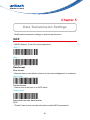
Chapter 5
Data Transmission Settings
- Modify data transmission settings to optimize performance.
ISCP
- MS920 Scanner Control Protocol parameters.
ISCP (*)
None
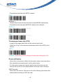
Data format
Raw format
- Barcode data is sent without a frame and no acknowledgement is necessary.
Raw format
Packet format
- Data is sent to the host in an ISCP frame.
Packet format
Extended barcode data format
BCD
- "Packet" data format must be activated to enable BCD transmission.
- 96 -
- Precedes barcode data with "[BCD]" indicator.
BCD
BCDEX (*)
- "Packet" data format must be activated to enable BCDEX transmission.
- Precedes barcode data with "[BCDEX]" indicator and extended
BCDEX (*)
DPS
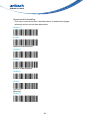
Transmission frame size (TFS)
- Length of the longest frame that can be received by the host.
- Value from 32 up to the maximum transmission frame size (MTFS) of the
scanner.
2048 (*)
Compose: Please refer to SCM (Software Configuration Manager) in CD
Event notification
- When active, the scanner notifies the host when certain events take place.
- Only available when data format is set to packet format.
- For information on the event frames that the host will receive from the
scanner see the ISCP online help available in the help menu in Easyset.
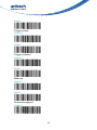
ISCP barcode
- When active the scanner informs the host of the following information after
reading and processing an ISCP bar code:
- 97 -
- Error (if any)
- Type of ISCP bar code (setup, status, etc.)
- GID
- FID
- Parameter
- For information on the event frame received by the host see the ISCP online
help available in the help menu in Easyset.
Disable
Enable (*)
Preprocessing ISCP barcode
- When active the scanner informs the host of the following information after
reading but BEFORE processing an ISCP bar code:
- GID
- FID
- Parameter
- For information on the event frame received by the host see the ISCP online
help available in the help menu in Easyset.
Disable (*)
Enable
- 98 -
Unsuccessful decoding
- This event is sent whenever a decode session is deactivated (trigger
released) and no decode has taken place.
Disable (*)
Enable
Start of read session
Disable(*)
Enable
End of read session
Disable(*)
Enable
Start-up
Disable(*)
- 99 -
Enable
Trigger pulled
Disable(*)
Enable
Trigger released
Disable(*)
Enable
Wake-up
Disable(*)
Enable
Structured append
Disable(*)
- 100 -
Enable
Symbology identifier
[symbology id] [data]
Not transmitted(*)
AIM format
[AIM symbology id] [data]
- Activates for all symbologies the 3-character symbology identifier
standardized by the AIM Committee.
- Example: "] A 0" identifies standard Code 39 without check digit[[[ If the
data in a bar code is modified (ISBN, . . .), the standard AIM identifier for the
symbology will be replaced by "]X0"]]].
NOTE: Depending on how the bar
AIM format
User Defined Identifier
[UDSI symbology id] [data]
- Activates user defined symbology identifier (UDSI) transmission for all
symbologies.
- NOTE: To change the default values go to "Symbology/select symbology/
symbology identifier/UDSI" and use the compose option.
User Defined Identifier
- 101 -
Code Mark
[preamble] [code mark symbology id] [data] [postamble]
- Activates code mark symbology identifier transmission for all symbologies.
NOTE: To change the default values go to "Symbology/select symbology/
symbology identifier/code mark" and use the compose option.
Code Mark
Preamble
[preamble] [symbology id] [data] [postamble]
None(*)
Compose: Please refer to SCM (Software Configuration Manager) in CD
Postamble
[preamble] [symbology id] [data] [postamble]
Carriage Return + Line Feed (*)
None
Compose: Please refer to SCM (Software Configuration Manager) in CD
- 102 -
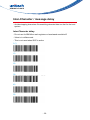
Inter-Character / message delay
- Avoids dropping characters if transmitting decoded data too fast for the host
system.
Inter-Character delay
- Do not use for IBM 46xx cash registers or laser/wand emulation!!!
- Value is in milliseconds.
- This is not used when ISCP is active
0 (*)
10
20
30
40
50
- 103 -
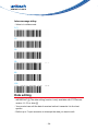
Inter-message delay
- Value is in milliseconds.
0 (*)
10
30
50
80
100
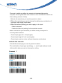
Data editing
- IMPORTANT [[[[ The data editing function is only available with STCDecode
version 1.1.5.0 or later ]]]]
- Your product can edit the data it receives before it transmits it to the host
system.
- Define up to 7 input scenarios to intercept the data you want to edit.
- 104 -
- The order in which you define the scenarios is important (the product
compares incoming data with each scenario in turn and edits the data for the
first matching scenario it finds).
1.Activate the scenario(s) you want the product to detect.
2.Define the input data you want to intercept for editing (any combination of
input type, input length, input mask).
3.Define the actions (editing) you want to apply to this input:
- Select a scenario
- Define the Action list (editing) for the selected scenario
- Make sure that the input scenarios you define actually correspond to
incoming data conditions:
- Correct input type ('all' = all input types)
- Correct input length ('0' = all input lengths)
- Correct input mask (no value = all input character combinations)
Activate the scenario
- Activate the scenario(s) you want the product to detect.
- The combination of input type (symbology, ...), input length and input mask
defines which data you want to intercept for editing.
Scenario 1
Disable (*)
Enable
Select barcode Type:
- 105 -
Compose barcode length:
Compose mask:
Scenario 2
Disable (*)
Enable
Select barcode Type:
Compose barcode length:
Compose mask:
Scenario 3
Disable (*)
- 106 -
Enable
Select barcode Type:
Compose barcode length:
Compose mask:
Scenario 4
Disable (*)
Enable
Select barcode Type:
Compose barcode length:
- 107 -
Compose mask:
Scenario 5
Disable (*)
Enable
Select barcode Type:
Compose barcode length:
Compose mask:
Scenario 6
Disable (*)
Enable
- 108 -
Select barcode Type:
Compose barcode length:
Compose mask:
Scenario 7
Disable (*)
Enable
Select barcode Type:
Compose barcode length:
Compose mask:
- 109 -
Chapter 6
Configuration Modes and Utilities
Get firmware version
- Get version info.
Get firmware version
Get decode version
- Get decode version info.
Get decode version
Get asub-system versions
- Get all component versions.
Get asub-system versions
Optical setup (using configuration bar codes)
- Use configuration bar codes to set up the product.
Always enabled
- Configuration with bar codes possible all the time.
- 110 -
Always enabled
Inhibit after 1 mn
- Protects the product against unwanted configuration by bar code.
- Configuration with bar codes only possible before end of 1 minute timeout
(cycle repeated until no config code read within 1 minute).
Inhibit after 1 mn
Transparent configuration mode
- Allows you to use your scanner to set up other products (setup commands
are transmitted to the other product but do not affect your scanner).
- Read unconcatenated configuration codes from the setup sheet to set up
another product in transparent configuration mode (not possible with EasySet
online).
Disable (*)
Enable
- 111 -
Appendix I
Worldwide Support
Unitech’s professional support team is available to quickly answer questions or
technical-related issues. Should an equipment problem occur, please contact
the nearest Unitech regional service representative. For complete contact
information please visit the Web sites listed below:
Region
Web Site
Global Operation Center
http://www.ute.com
Unitech Taiwan
http://tw.ute.com
Unitech Asia Pacific & Middle East
http://apac.ute.com
http://india.ute.com
Greater China Division
http://cn.ute.com
Unitech Japan
http://jp.ute.com
Unitech North America
http://us.ute.com ; http://can.ute.com
Unitech Latin America
http://latin.ute.com
Unitech Europe
http://eu.ute.com
- 112 -