1
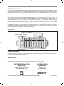
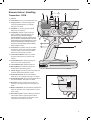
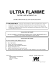
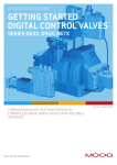
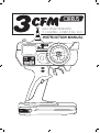
High performance
3 CHANNEL Computer R/C
INSTRUCTION MANUAL
D I S P L AY
L
Safety Precautions
Thank you for purchasing this CIRRUS 3CFM computer radio control system. Before using this radio, and to ensure
your safety and that of others, it is important that you read this manual thoroughly, and understand it, prior to
installation and operation. After reading this manual thoroughly, store it in a safe place so that you can easily find it
again should the need arise.
Just as commercial radio stations have their own frequency bands, so do radio control systems. Each radio
control system comes with a sticker on the transmitter and on the receiver showing which basic frequency the
radio control system operates on (27MHz, 40MHz or 75MHz band). Each main frequency is broken down into
various sub-frequencies, called channels (e.g. 27.045MHz, 27.145MHz, etc.), which allow multiple models to
operate together without interference. In order to be able to operate on different channels the transmitter and
receiver are fitted with removable crystals. Each crystal will have its actual frequency printed on it and details
of whether it is for transmitter (Tx) or receiver (Rx). Crystals are matched in pairs (e.g. Tx 27.145MHz and Rx
27.145MHz). Transmitter and receiver crystals (matched pairs) can be purchased separately and changed if
interference is detected (someone operating on the same frequency as you). As a rule it is always good to carry
at least one spare pair of crystals to allow for this possibility.
Note: The 3CFM transmitter has a location to store a spare pair of crystals located inside its battery
compartment.
Battery Compartment
Spare Crystal Storage
Before Operation
Should any item be missing or if you are uncertain of the contents of the system, please contact the dealer from
whom you purchased the system before use.
27MHz and 75MHz
These frequencies are legal for use in North America.
27MHz and 40MHz
These frequencies are legal for use in Europe, but can vary from country to country.
DISTRIBUTED IN NORTH
AMERICA BY:
DISTRIBUTED IN
EUROPE BY:
Global Hobby Distributors
18480 Bandilier Circle
Fountain Valley, CA 92708
Ripmax Ltd.
241 Green Street
Enfield, EN3 7SJ, U.K.
The contents of this manual are subject to change without prior notice.
2
Ref: 3CFM1
Nomenclature / Handling
1
4
Transmitter: 3CFM
5
2
8
9
1. Antenna
2. Power Switch: Turns your transmitter ON & OFF.
3. Charging Jack: For onboard charging when
using rechargeable batteries (not supplied).
See page 5 For details.
4. Strap Base: For the securing of an optional
safety strap (not supplied).
SEL
5. LCD Display: Displays all menu screens for
function updates, power level indicator, etc.
Note: Once you have finished making any
function adjustments (using the ‘Function Select’
and ‘DT1’ buttons), wait approximately 6 seconds
without making any further adjustments to set the
change. As this happens you will see the screen
will return to its normal display mode, indicating
10
D I S P L AY
CONTROL SYSTEM
3
7
that the change is saved.
6. LED Indicator: Illuminates when the transmitter
is switched on, blinks when transmitter displays
low power. Works in conjunction with audible
beeps when making function changes.
6
11
12
14
13
7. Function Select Button: Allows you to select
the menu screens that let you make function
updates.
15
8. Function Button DT1: Operates steering trim
and is main function changing button.
9. Function Button DT2: Operates throttle trim.
10. Steering Wheel: Proportionally operates the
model’s left and right steering control.
11. Throttle Trigger: Controls the speed of the model and
movement forward and backward, or brake.
12. Function Button DT3: Allows quick Dual Rate
adjustment for Ch1 (Steering). See page 7 For details.
13. Function Button DT4: Allows quick EPA adjustment for
Ch2 (Reverse/Brake). See page 9 For details.
14. Ch3 Button: Used to operate a third function, like
reversing on an engine-powered car. See page 9 For
details.
16
15. Battery Compartment: Houses batteries (AA/UM3) that
power the transmitter. Also includes holder for a pair of
spare crystals.
16. Transmitter Crystal: Crystals on differing frequencies
allow multiple models to operate together without
interference and are matched in pairs with a similar
crystal fitted to the receiver in the model.
3
Battery Installation / Replacement Method
1. Remove the battery cover from the base of the transmitter by sliding it in the direction of the arrow embossed on
the cover itself.
2. Insert 8 x AA/UM3 batteries (fresh dry cell or fully charged rechargeable recommended), ensuring the batteries
are fitted the right way round, observing the + and - signs on each battery.
3. Slide the battery cover back into place until it is fully seated.
Note 1: Do not mix old and new batteries. Do not mix dry cell and rechargeable batteries.
Note 2: If you do not intend using your model for an extended period, we recommend that you remove all
batteries from the radio and the model and store them safely until needed again.
Note 3. If batteries do leak, clean battery case and contacts thoroughly - plastic parts can be wiped clean with
a damp (not wet) cloth with mild detergent and metal contacts with an alcohol based liquid, being careful to
avoid getting battery residue on your skin. Always perform any clean up of this kind in a well ventilated area,
taking care to observe all warning labels on the cleaning products themselves.
Check
Turn the power switch on your transmitter to the ‘ON’ position. The LED indicator will glow red and you will hear 3 audible
beeps. At the same time, the LCD screen will illuminate. If the LED fails to light, no beeps are heard and the LCD display
fails to illuminate, double check that you have installed the batteries the correct way round in the transmitter and try
again. If the LED still fails to light and no audible beeps are heard, check that the batteries you have installed are fully
charged.
Note: The Cirrus 3CFM transmitter is not reverse polarity protected. Always ensure that you put the batteries
in the correct way round or damage to the transmitter will result. For ease of identification, there are raised
images of each battery in the battery tray to indicate correct orientation.
Battery Power Display
When the red LED is lit, and the LCD display shows battery power of
12v ~ 8v, there is sufficient power for use.
When transmitter voltage drops below 8v, the LED indicator will start to flash
and an audible beep will be emitted every 2 seconds. At the same time a
low battery warning symbol will appear in the lower right hand portion of the
LCD display. At this time you should immediately stop using the radio and
replace/recharge the batteries or control will be lost.
Running Preparations / Safety Precautions
Warning!
(When using NiCad / Ni-MH rechargeable batteries to power your R/C system)
When using NiCad / Ni-MH batteries to power your R/C system, ensure the batteries are fully charged prior to
operation, or control of your vehicle could/will be lost.
4
Charging (For Rechargeable Batteries)
Caution!
Never try to charge dry cell batteries in the transmitter. They will leak and could explode.
To prevent the possibility of accident, overheating and/or short circuit, always disconnect your battery charger from
its power supply when not in use.
For UK/Europe
We recommend the Ripmax P-FBC10D/4 (UK) / P-FBC10D/4EUR (Europe), Tx/Rx NiCad/Ni-MH AC Charger
70/70mA, to charge rechargeable batteries in the Cirrus 3CFM transmitter and suitable rechargeable receiver battery
packs (where applicable).
Note: Do not dispose of Ni-Cad/Ni-MH batteries in household waste, but take them to a designated recycling
centre.
For North America
To charge rechargeable batteries in the Cirrus 3CFM transmitter you will require a 9.6V charger with an output of
70mA. The charging jack centre pin must be the positive connection.
Note: Some states have special requirements concerning the disposal of rechargeable batteries. You should
first check with the State Agency responsible for recycling hazardous waste for procedures in your State!
When disposing of used rechargeable batteries, always cover any exposed contacts with some form of
insulation/tape to prevent short circuit.
Servo Trims
The servo trims on the 3CFM are digital and are adjusted from the ‘DT1’ and DT2’ buttons arranged around the
transmitter’s steering wheel. Adjustment is very simple. The amount of adjustment can be viewed on the display
screen positioned to the left of the steering wheel. Each servo trim can be adjusted from 0% to 100%.
Note: Trims should be checked every time you intend to use your model. This is a quick and simple procedure
that ensures that you have effective control over your model.
Steering Trim Function
The steering trim allows you to fine-tune the position of the steering servo so as to give correct steering response.
Place your model on a flat, level surface and drive it slowly forwards without touching the steering wheel. If your model
drives in a straight line, no adjustment is necessary. If your model pulls either to the left or right when the steering
wheel is NOT being turned, it needs adjustment. Adjustment is as follows and should be performed with your model
driving slowly forwards (the steering trim is adjusted using the ‘DT1’ button located above the steering wheel):
1. If your model pulls to the left without transmitter input (turning the steering wheel), push the ‘DT1’ button to the right
to trim the steering servo, re-centre your model using the steering wheel and then drive forward again without steering
and see what effect your adjustment has made.
2. Keep fine-tuning the trim in this way using the ‘DT1’ button until your model drives in a straight line without touching
the steering wheel. You can adjust the trim in 1% increments for fine-tuning, or press and hold the ‘DT1’ button for
faster adjustment if the steering is badly out of trim.
3. To adjust the trim when your model pulls to the right without transmitter input, simply push the ‘DT1’ button to the
left in the same way as explained above.
Note: If you need to adjust the trim to a too large a degree, it may be that you need to re-set/re-centre the
servo output arm/servo saver on top of the servo and trim again as necessary. When doing this, be sure to
have both the transmitter and receiver switched ‘ON’, and to set the servo’s trim on the transmitter back to
0%, before re-attaching the arm/servo saver so that the servo is returned to its actual neutral position.
5
Throttle Trim Function
The throttle trim allows you to fine-tune the position of the throttle servo or speed controller so as to give correct
throttle response. When you first switch ‘ON’ your transmitter and model (and start the engine in the case of an engine
powered model), the drive wheels on the model should not be turning. This is the neutral position. If the drive wheels
are turning (either forwards or reverse), you can adjust the throttle trim to stop them and bring your model back to
neutral. Throttle servo trimming is best done with the model’s drive wheels off the ground to ensure that you do not
have a runaway model whilst your are adjusting the trim.
You adjust the throttle trim using the ‘DT2’ button located at the left side of the steering wheel.
Push the ‘DT2’ button up or down to trim the throttle servo so that the model’s wheels are not turning. Pulling the
transmitter’s trigger should give almost immediate acceleration and pushing the trigger forward should give almost
immediate reverse (electric) or brake (nitro/engine) operation. You can fine-tune the trim to set this correctly. Note,
some electric models are fitted with electronic speed controllers that have a dual brake/reverse function. In this case,
it may be necessary to push the trigger several times to operate reverse.
Note 1: If by adjusting the throttle trim the model’s wheels begin to turn faster, you are adjusting the wrong
way. In this case, simply adjust in the opposite direction until the wheels stop turning.
Note 2 : If you need to adjust the trim to a too large a degree, it may be that you need to re-set/re-centre the
servo output arm’s position on top of the servo and trim again as necessary. When doing this, be sure to
have both the transmitter and receiver switched ‘ON’, and to set the servo’s trim on the transmitter back to
0%, before re-attaching the servo arm so that the servo is returned to its actual neutral position.
Description of Functions
If a servo operates in the opposite direction to that required, e.g., turning the transmitter’s steering wheel left causes
the model to steer right, or pulling the trigger for forward movement causes the model to travel in reverse or applies
the brake, you can correct the servo’s movement with the appropriate reverser.
Servo Reversing on CH1 (Steering)
Press the
button once in normal
display mode to enter the Servo
Reversing setting menu for Channel 1.
Push the ‘DT1’ button either left or right
to set a normal (NOR) or reversed (REV)
control state.
Note: The default state is normal
(NOR) state.
Servo Reversing on CH2 (Throttle & Reverse/Brake)
Press the
button twice in normal
display mode to enter the Servo
Reversing setting menu for Channel 2.
As for Ch1 adjustment above, push the
‘DT1’ button either left or right to set a
normal (NOR) or reversed (REV) control
state.
Note: The default state is normal
(NOR) state.
6
Dual Rates
Dual Rate function allows you to vary the amount the servo moves (or speed controller responds) in response to
transmitter inputs and reduces/increases the movement/response evenly, left and right of centre/neutral. As a result,
you can set your model up to have very little response, a lot of response, or somewhere in between. This can be
easily adjusted to your own preference depending on the type of surface you are running the model on and the
handling characteristics you want. An example of this would be your model’s steering (Ch1), where you might want
to increase servo movement (and increase sensitivity) for tracks with tighter turns or decrease servo movement (and
decrease sensitivity) on wider, more open tracks.
Dual Rate Setting on CH1 (Steering)
Press the
button three times in
normal display mode to enter the Dual
Rate setting menu for Channel 1.
Push the ‘DT1’ button to the left to
decrease Dual Rate and to the right to
increase Dual Rate. The changing range
is from 100% down to 5%, moving in 1%
increments.
Dual Rate Setting on CH2 (Throttle & Reverse/Brake)
Press
button four times in normal
display mode to enter the Dual Rate
setting menu for Channel 2.
Push the ‘DT1’ button to the left to
decrease Dual Rate and to the right to
increase Dual Rate. The changing range
is from 100% down to 5%, moving in 1%
increments.
Steering Dual Rate Adjustment with ‘DT3’ Button
This function allows the quick change of steering dual rate without having to access the on screen menu using the button and then scroll through the various screens, and is useful for making quick function changes when at
the track or similar. The button works the same as ‘DT1’ above, with the same percentage range of change and
percentage increments of change. Also, changes made using the ‘DT3’ button will show on the LCD display.
End Point Adjustment (EPA)
End Point Adjustment (EPA), also sometimes referred to as Adjustable Travel Volume (ATV), allows you to set the
maximum travel (movement) of each servo, but independently either side of neutral (centre). This will allow you to set a
deliberate bias of servo movement from one side of neutral (centre) to the other. A good example of this might be where
you want to have more left steering response than right, for example, when running a car on an oval track.
The EPA function on Ch2 is especially useful in setting servo (or speed controller) bias between forward operation
and reverse or brake function. Also, it will allow you to set different braking positions on an engine powered car
without having to physically adjust the brake linkage, allowing increased or reduced braking response dependent on
differing track conditions, all adjusted from the transmitter.
7
EPA Setting on CH1 (Steering to the Left)
Press the
button five times in normal
display mode to enter the EPA setting
menu for Channel 1, steering to the left.
Push the ‘DT1’ button to the left to
decrease servo movement to left of
centre and to the right to increase
servo movement to left of centre. The
changing range is from 120% down to
5%, moving in 1% increments.
EPA
EPA
EPA Setting on CH1 (Steering to the Right)
Press the
button six times in normal
display mode to enter the EPA setting
menu for Channel 1, steering to the
right.
Push the ‘DT1’ button to the left to
decrease servo movement to right
of centre and to the right to increase
servo movement to right of centre. The
changing range is from 120% down to
5%, moving in 1% increments.
R.B.D
R.B.D
EPA
EPA
EPA
EPA
EPA Setting on CH2 (Throttle)
Press the
button seven times in
normal display mode to enter the EPA
setting menu for Channel 2, throttle
(accelleration).
Push the ‘DT1’ button to the left to
decrease EPA and to the right to
increase EPA. The changing range is
from 120% down to 5%, moving in 1%
increments.
EPA Setting on CH2 (Brake/Reverse)
Press the button
eight times in
normal display mode to enter the EPA
setting menu for Channel 2, brake/
reverse.
Push the ‘DT1’ button to the left to
decrease EPA and to the right to
increase EPA. The changing range is
from 120% down to 5%, moving in 1%
increments.
8
R.B.D
EPA
R.B.D
EPA
EPA Setting on CH2 (Brake/Reverse), with ‘DT4’ Button
This function allows the quick change of reverse/braking EPA without having to access the on screen menu using the button and then scroll through the various screens, and is useful for making quick function changes when at the
track or similar. The button works the same as ‘DT1’ above, with the same range of change and increments of change.
Also, changes made using the ‘DT4’ button will show on the LCD display.
Channel 3
The 3rd channel on the 3CFM works in such a way that a single push of the button on the transmitter’s grip will cause
the servo arm to move through a set amount of travel in one go. A second push of the button will cause the servo arm
to return to its start point (neutral). An ideal application for this would be the reverse operation in an engine powered
car, where a gearbox is required to effect the change from forward movement to reverse movement.
Trim Function Setting on CH3
This function allows you to trim the 3rd
channel servo in the model to set a
specific neutral position.
Press the
button nine times in normal
display mode to enter the Trim setting
menu for Channel 3.
Start with the percentage setting at -0%
using the ‘DT1’ button as necessary.
Once the servo arm is fitted to the servo,
you can fine-tune the arm’s position to set your preferred neutral position. The changing range is from -0% up to 100%, moving in 1% increments. It may be necessary to re-position the servo horn whilst doing this.
Note: It is important that you ensure the 3rd channel button is in its neutral position before setting a servo
up in your model. If the 3rd channel button is in the correct position, once you select the Trim function for
channel 3, you should immediately notice the servo’s output arm moving in response when you press the
‘DT1’ button to either the left or right. If it does not, push the 3rd channel button on the transmitter once
and the servo will return to its neutral position (the servo arm will move back to neutral). Now the servo arm
should respond to adjustments to the trim function using the ‘DT1’ button.
EPA Function Setting on CH3
This function allows you to trim the
3rd channel servo’s EPA in the model
to set a specific percentage/amount of
movement from neutral.
Press the
button ten times in normal
display mode to enter the EPA setting
menu for Channel 3.
+
+
Use the ‘DT1’ button to increase or
decrease servo arm movement as
required. The changing range is from +0% up to +100%, moving in 1% increments.
Note: Press the 3rd channel button and the servo arm will move through a set amount of travel. If the amount
is too much or too little, you can fine-tune it using the EPA function.
9
Anti-Lock Braking System (ABS) Setting on CH2
(Throttle & Reverse/Brake)
Slowing or stopping a car in slippery or loose conditions can be quite challenging. Simply locking the wheels, as in
conventional braking, will cause a loss of traction and steering control, resulting in an out-of-control slide. ABS allows
you to slow down faster whilst still being able to steer effectively by ‘pulsing’ the brake function so that the wheels do
not actually lock up.
In this mode, you have 4 settings; ‘OFF’,
‘FST’, ‘MID’ and ‘SLW’. In the ‘OFF’
mode, ABS does not function. ‘FST’,
‘MID’ and ‘SLW’ relate to Fast, Medium
and Slow ABS operation and basically
allow you to fine-tune how the ABS will
work on your model dependent on the
track surface you are running on.
Press the
button eleven times in normal display mode to enter the ABS setting menu for channel 2.
The default setting is ‘OFF’. To select either ‘FST’, ‘MID’ or ‘SLW’ (Fast, Medium or Slow), simply move the ‘DT1’
button to the right (or back to the left) to choose the required setting.
Model Memory
The Cirrus 3CFM transmitter has 10 model memories (0~9), allowing you to preset the details of up to 10 different
models on this transmitter.
How To Set A Model Memory
With your transmitter switched ‘OFF’, press and hold the
button and then switch your transmitter ‘ON’ whilst
continuing to hold down the
button. At this point a flashing image of the memory number in use will show on the
LCD screen, indicating that you have accessed the system’s memory menu mode.
Push the ‘DT1’ button left or right to select the model memory number you require. There are 10 model memories or
modes, numbered 0 through 9. Once you have selected the appropriate model memory/mode, you can adjust it as
required using the
and ‘DT1’ buttons as detailed previously. The new selection will set after 8 seconds.
In this way, you can preset parameters for up to 10 models in advance and simply select the appropriate model
memory when you want to use a particular model, rather than having to re-adjust your transmitter every time you want
to switch models. Just remember to make a note of which model represents which memory!
Note: If no changes are made within 20 seconds the model memory function being selected, the number will
stop flashing and the LCD screen will revert back to the normal front screen display.
Necessary Testing
Prior to operation, always perform a range check of your model.
(Range Check Procedure - Electric Powered Car)
Install a fully charged NiCad/Ni-MH battery pack in the model. Switch on the transmitter, then the receiver. Ideally,
have a friend hold the model or place it on a stand where the drive wheels cannot come into contact with the ground.
Leaving the transmitter’s aerial fully retracted, move approximately 10m (30 feet) from the model. Now, check that the
movement of each servo responds to transmitter inputs for both steering and throttle.
Note 1: If the servos do not follow the commands from the transmitter or any type of interference is detected,
DO NOT operate the model. Check that all batteries are fully charged and ensure that nobody else is operating
on your radio’s frequency.
Note 2: Before use, fully extend the transmitter’s aerial or operating range will be reduced and control
could/will be lost.
10
(Range Check Procedure - Engine Powered Car)
Install fully charged batteries (either dry or rechargeable) in the model. Switch on the transmitter, then the
receiver. Follow the engine starting procedure. Ideally, have a friend hold the model or place it on a stand where
the drive wheels cannot come into contact with the ground. Leaving the transmitter’s aerial fully retracted, move
approximately 10m (30 feet) from the model. Now, check that the movement of each servo responds to transmitter
inputs for both steering and throttle.
Note 1: If the servos do not follow the commands from the transmitter or any type of interference is
detected, DO NOT operate the model. Check that all batteries are fully charged and ensure that nobody else
is operating on your radio’s frequency.
Note 2: Before use, fully extend the transmitter’s aerial or operating range will be reduced and control
could/will be lost.
RUNNING SAFETY PRECAUTIONS
Important!
• Always switch ‘ON’ your transmitter first, followed by the receiver. Always switch ‘OFF’ your receiver first,
followed by the transmitter. Failure to follow these procedures could result in a runaway model with the
possibility of damage to property and/or injury to yourself and/or others.
• Do not try to operate two or more models on the same frequency at the same time as this will cause
interference and loss of control of both/all models. AM, FM and PCM are all different methods of frequency
modulation. However, the same frequency cannot be used at the same point in time, regardless of
modulation type.
• Never operate your model in the rain or run it in water / through puddles or in mud. The transmitter,
receiver, most servos and most electronic speed controllers are NOT waterproof and contact with moisture,
immersion in water and/or snow will cause them to fail with resultant loss of control of your model. Should
any type of moisture enter any part of your radio system, stop using it immediately and return it to the
specified service centre for inspection/repair.
• Do not operate your model within 1.6Km (1 Mile) of another sight where radio control activity commonly
occurs. Interference from other radio systems operating on the same frequency as yours could/will result in
loss of control and possible injury to yourself and/or others, as well as possible damage to property.
• Do not operate your model where visibility is limited. Should you lose sight of your model a collision could
occur that may damage property and/or injure someone.
• Do not operate your model near people or next to/on public roads. Prior to the operation of your model
ensure that the area that you intend to operate in is safe to do so. Be aware of any objects that may obstruct
the operation of your model. Do not operate your model where people and/or other moveable objects may
stray into its path. Loss of control due to radio interference, component failure, obstructed sight or low
battery voltage could result in damage to property/the model and/or injury to yourself and/or others.
• When installing in an electric model, attach the receiver to the chassis or mounting plate with thick
double-sided tape. When installing in an engine powered model, wrap the receiver in foam rubber or a
similar padded material. Protect from water damage by securing in a plastic/rubber bag and/or placing
in a waterproof radio box. The receiver is made from precision electronic parts which can be harmed by
vibration, shock and/or moisture. Take every precaution to protect against these factors.
Never store your Cirrus R/C system where it could be exposed to the following conditions:
• Extremes of heat or cold
• Direct sunlight
• High humidity environments
• High vibration environments
• Dusty environments
11
• Near steam and/or condensation
• Where the system could be exposed to engine exhaust
Note: Storing your Cirrus R/C system under the conditions outlined above can result in deteriation/
deformation of the casing and damage to the electronics.
Receiver, Servo and Speed Controller Connection
Note: Use base illustrations as created for the 2CAM instructions, although these will need to be
modified slightly to show 3rd channel servo.
Connections for installation in an electric powered model. Connections for installation in an engine powered model. (CH3)
Possible Reverse Gear/
Other Purpose
(CH2)
(CH1)
Assembly Precautions
Important
• Periodically check the receiver, servos and battery connectors to be sure that all are firmly joined. If a connector
is not fully inserted, vibration can cause it to work loose while your model is operating, resulting in a loss of
control.
• The receiver aerial may seem overlong, but its length is critical - DO NOT cut it. If the length of the receiver
aerial is altered, the receiver will be adversely affected, resulting in reduced range and/or loss of control.
• Ensure that the receiver is mounted at least 13mm (1/2 inch) away from any devices that give off high frequency
noise; motors, batteries and wiring that can handle high current loads. High frequency noise will cause a
reduction in operating range and can cause loss of control.
12
Technical Information
The CIRRUS 3CFM computer radio control system is supplied with differing servos, depending on its application.
You should check your own model to ensure which type(s) is/are installed. A list of specifications for the most
common types is given below.
Transmitter 3CFM (3 Channel, FM type)
Transmitting Frequency: 27/40MHz
Modulation Method: FM
Power Requirement: 12V (8 x AA)
Receiver 3CFM RX (3 Channel, FM type)
Receiving Frequency: 27/40MHz
Power Requirement: 4.8~6V
Size: 37x25x13mm / 1.46x0.98x0.51in
Weight: 13g / 0.46oz
Servo CDS751/MG (High Torque, Ballraced Digital Servo)
Speed: 0.26 sec/60° (4.8V) / 0.22 sec/60° (6.0V)
Torque (4.8V): 13Kg/cm / 149oz/in
Torque (6.0V): 11Kg/cm / 153oz/in
Dimensions: 40.6x19.8x37.8mm / 1.6x0.78x0.48in
Weight: 55g / 1.93oz
Servo CS601/BB (High Torque, Ballraced Standard Servo)
Speed: 0.20 sec/60° (4.8V) / 0.16 sec/60° (6.0V)
Torque (4.8V): 5.5Kg/cm / 75oz/in
Torque (6.0V): 6.5Kg/cm / 102oz/in
Dimensions: 40.6x19.8x37.8mm / 1.6x0.78x1.48in
Weight: 55g / 1.93oz
Servo CS703/MG (Metal Geared, Ballraced Servo)
Speed: 0.22 sec/60° (4.8V) / 0.18 sec/60° (6.0V)
Torque (4.8V): 5.5Kg/cm / 75oz/in
Torque (6.0V): 7.5Kg/cm / 102oz/in
Dimensions: 41x20x38mm / 1.61x0.79x1.5in
Weight: 56g / 1.9oz
Servo CS704/MG (Metal Geared, High Torque Servo)
Speed: 0.17 sec/60° (4.8V) / 0.15 sec/60° (6.0V)
Torque (4.8V): 13Kg/cm / 181oz/in
Torque (6.0V): 14.6Kg/cm / 195oz/in
Dimensions: 40.5x20x41mm / 1.6x0.78x0.61in
Weight: 46g / 1.73oz
*Specifications and ratings are subject to change without prior notice.
13
Troubleshooting
PROBLEM CAUSE REMEDY
Model will not move/ No batteries in transmitter/model does not recieve a
signal
Battery installation is incorrect Install batteries correctly, noting + & - symbols
Replace/recharge batteries
Weak batteries in transmitter Install batteries
Weak batteries in model Replace/recharge batteries
Radio interference Relocate or change crystals
Connector disconnection Reinsert connector(s)
Tx/Rx* crystal disconnected Push in crystal(s)
Dirty battery contacts ON/OFF switch in ‘OFF’ position
Wipe clean with dry cloth
Replace ON/OFF switch
ON/OFF switch is defective
Move ON/OFF switch to ‘ON’ position
No control of model Weak batteries in transmitter Replace/recharge batteries
Weak batteries in model Replace/recharge batteries
Radio interference Relocate or change crystals
Limited radio range/ Weak batteries in transmitter interference
Weak batteries in model Replace/recharge batteries
Transmitter aerial loose Tighten transmitter aerial
Replace transmitter aerial
Transmitter aerial cannot be extended
Replace/recharge batteries
Receiver aerial damaged/cut Return receiver for repair
Motor (electric model) not suppressed
Fit motor suppressors
* Tx = Transmitter / Rx = Receiver
Please retain this information for future reference.
14
Warranty Information
In North America
Your Cirrus 3CFM computer radio system is warranted against manufacturer defects in materials and workmanship
for a period of 90 days from the date of purchase. Warranty service will be provided within 90 days of the date of
purchase only if you are able to provide the original or a copy of the original dated sales receipt.
In the United Kingdom/Europe
Your Cirrus 3CFM computer radio system is warranted against manufacturer defects in materials and workmanship
for a period of 1 (one) year from the date of purchase. Warranty service will be provided within 1 (one) year of the
date of purchase only if you are able to provide the original or a copy of the original dated sales receipt. This does
not affect your statutory rights.
Cirrus is not responsible for the unauthorised modification, adjustment and/or replacement of parts of this product.
Neither is Cirrus responsible for the use of this product.
Important Warranty Service Information
Before returning your Cirrus 3CFM computer radio system for warranty consideration, please re-read this instruction
manual to be sure that you are operating this radio control system correctly. Please also note that the status of the
system must be within the Warranty Service Information as detailed below. Please do not return your Cirrus 3CFM
computer radio system to the place of purchase. They are neither authorised nor equipped to perform warranty
work on Cirrus products. When requesting warranty service, please observe the following:
• Crash damage will not be covered under warranty, nor will a dropped transmitter be covered. Do not request
warranty service for crash-damaged or dropped product.
• Always return the whole system; transmitter, receiver, switch and battery box (if supplied). Include details all
of the items that you are returning. Always remove all batteries from the system before returning it.
• Include a note detailing the problem or service you are requesting. Service cannot be provided without this
information. Please include a daytime telephone number, your home address and an email address that you
can be reached at in case we need more details pertaining to the service requested.
• If your system is out of its warranty period you may request an estimate of services at the time you return it
for service. An omission of this request implies permission for Global Services / Ripmax Ltd. to service your
system at our discretion.
• Please include a method of payment for any service charges.
• Send the system to us by United Parcel Service, Federal Express or Insured Mail. Return postage is nonrefundable. Send your package to:
IN NORTH AMERICA:
IN EUROPE:
Global Services
18480 Bandilier Circle
Fountain Valley, CA 92708
Ripmax Ltd.
241 Green Street
Enfield, EN3 7SJ, U.K.
Phone: (714) 963-0329
Fax: (714) 964-6236
Email: [email protected]
Phone: +44(0) 20 8282 7500
Fax: +44(0) 20 8282 7501
Email: [email protected]
All contents copyright circa 2007, Version 1 June 2007
15