1
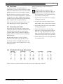
LTC 8561, 8564/20, 8566 Series
Instruction Manual
EN Single Channel
On-site
Receiver/Drivers
8561 | Instruction Manual | Important Safeguards
EN | 2
Important Safeguards
1. Read, Follow, and Retain Instructions - All safety
and operating instructions should be read and
followed before operating the unit. Retain instructions
for future reference.
2. Heed Warnings - Adhere to all warnings on the unit
and in the operating instructions.
3. Attachments - Attachments not recommended by
the product manufacturer should not be used, as they
may cause hazards.
4. Installation Cautions - Do not place this unit on an
unstable stand, tripod, bracket, or mount. The unit
may fall, causing serious injury to a person and
serious damage to the unit. Use only manufacturerrecommended accessories, or those sold with the
product. Mount the unit per the manufacturer's
instructions. Appliance and cart combination should
be moved with care. Quick stops, excessive force, or
uneven surfaces may cause the appliance and cart
combination to overturn.
5. Cleaning - Unplug the unit from the outlet before
cleaning. Follow any instructions provided with the
unit. Generally, using a damp cloth for cleaning is
sufficient. Do not use liquid cleaners or aerosol
cleaners.
6. Servicing - Do not attempt to service this unit
yourself. Opening or removing covers may expose
you to dangerous voltage or other hazards. Refer all
servicing to qualified service personnel.
7. Damage Requiring Service - Unplug the unit from
the main AC power source and refer servicing to
qualified service personnel under the following
conditions:
• When the power supply cord or plug is damaged.
• If liquid has been spilled or an object has fallen
into the unit.
• If the unit has been exposed to water and/or
inclement weather (rain, snow, etc.).
• If the unit does not operate normally, when
following the operating instructions. Adjust only
those controls specified in the operating
instructions. Improper adjustment of other controls
may result in damage, and require extensive work
by a qualified technician to restore the unit to
normal operation.
• If the unit has been dropped or the cabinet
damaged.
• If the unit exhibits a distinct change in
performance, this indicates that service is needed.
8. Replacement Parts - When replacement parts are
required, the service technician should use
replacement parts specified by the manufacturer or
that have the same characteristics as the original part.
Unauthorized substitutions may result in fire,
electrical shock or other hazards.
9. Safety Check - Upon completion of servicing or
repairs to the unit, ask the service technician to
perform safety checks to ensure proper operating
condition.
Bosch Security Systems | 30 January 2004
10. Power Sources - Operate the unit only from the type
of power source indicated on the label. If unsure of
the type of power supply to use, contact your dealer
or local power company.
• For units intended to operate from battery power,
refer to the operating instructions.
• For units intended to operate with External Power
Supplies, use only the recommended approved
power supplies.
• For units intended to operate with a limited power
source, this power source must comply with
EN60950. Substitutions may damage the unit or
cause fire or shock.
• For units intended to operate at 24 VAC, normal
input voltage is 24 VAC. Voltage applied to the
unit's power input should not exceed 30 VAC.
User-supplied wiring, from the 24 VAC supply to
unit, must be in compliance with electrical codes
(Class 2 power levels). Do not ground the 24 VAC
supply at the terminals or at the unit's power
supply terminals.
11. Coax Grounding - If an outside cable system is
connected to the unit, ensure that the cable system is
grounded. U.S.A. models only - Section 810 of the
National Electrical Code, ANSI/NFPA No.70,
provides information regarding proper grounding of
the mount and supporting structure, grounding of the
coax to a discharge unit, size of grounding
conductors, location of discharge unit, connection to
grounding electrodes, and requirements for the
grounding electrode.
12. Grounding or Polarization - This unit may be
equipped with a polarized alternating current line
plug (a plug with one blade wider than the other).
This safety feature allows the plug to fit into the
power outlet in only one way. If unable to insert the
plug fully into the outlet, try reversing the plug. If the
plug still fails to fit, contact an electrician to arrange
replacement of the obsolete outlet. Do not defeat the
safety purpose of the polarized plug.
Alternately, this unit may be equipped with a
3-wire grounding plug (a plug with a third pin, for
grounding). This safety feature allows the plug to fit
into a grounding power outlet only. If unable to insert
the plug into the outlet, contact an electrician to
arrange replacement of the obsolete outlet. Do not
defeat the safety purpose of the grounding plug.
13. Lightning - For added protection during a lightning
storm, or when this unit is left unattended and
unused for long periods of time, unplug the unit from
the wall outlet and disconnect the cable system. This
will prevent damage to the unit due to lightning and
power line surges.
EN | 3
8561 | Instruction Manual | Safety Precautions
For Indoor Product
1. Water and Moisture - Do not use this unit near
water - for example, in a wet basement, in an
unprotected outdoor installation or in any area
classified as a wet location.
2. Object and Liquid Entry - Never push objects of
any kind into this unit through openings, as they
may touch dangerous voltage points or short out
parts that could result in a fire or electrical shock.
Never spill liquid of any kind on the unit.
3. Power Cord and Power Cord Protection - For
units intended to operate with 230VAC, 50Hz,
the input and output power cord must comply
with the latest versions of IEC Publication 227 or
IEC Publication 245.
Power supply cords should be routed so they are
not likely to be walked on or pinched. Pay
particular attention to location of cords and plugs,
convenience receptacles, and the point of exit
from the appliance.
4. Overloading - Do not overload outlets and
extension cords; this can result in a risk of fire or
electrical shock.
Cover Removal
WARNING: Removal of the cover should only be
performed by qualified service personnel - not user
serviceable. The unit should always be unplugged before
removing the cover and remain unplugged while the
cover is removed.
24VAC Units
Do not exceed 30VAC input. Voltage applied to the unit's
power input should not exceed 30VAC. Normal input
voltage is 24VAC. User supplied wiring from 24VAC
supply to unit must be in compliance with electrical codes
(Class 2 power levels). Do not ground 24VAC supply at
power supply terminals or at unit's power supply terminals.
This equipment is to be isolated from the mains
supply by a limited power source as specified in
EN60950.
220-240V, 50Hz Power Cords
220-240V, 50Hz power cords, input and output, must comply
with the latest versions of IEC Publication 227 or IEC
Publication 245.
Safety Precautions
For Outdoor Product
Power Lines - An outdoor system should not be
located in the vicinity of overhead power lines,
electric lights or power circuits, or where it may
contact such power lines or circuits. When
installing an outdoor system, extreme care should
be taken to keep from touching power lines or
circuits, as this contact might be fatal. U.S.A.
models only - refer to the National Electrical
Code Article 820 regarding installation of CATV
systems.
For Rack-Mount Product
1. Ventilation - This unit should not be placed in a
built-in installation or rack, unless proper
ventilation is provided, or the manufacturer’s
instructions have been adhered to. The
equipment must not exceed its maximum
operating temperature requirements.
2. Mechanical Loading - Mounting of the
equipment in a rack shall be such that a
hazardous condition is not achieved due to
uneven mechanical loading.
Bosch Security Systems | 30 January 2004
CAUTION: TO REDUCE THE RISK OF
ELECTRIC SHOCK, DO NOT REMOVE COVER
(OR BACK). NO USER SERVICEABLE PARTS
INSIDE. REFER SERVICING TO QUALIFIED
SERVICE PERSONNEL.
This symbol indicates the presence of
uninsulated “dangerous voltage” within the
product’s enclosure. This may constitute a
risk of electric shock.
The user should consult the operating and
maintenance (servicing) instructions in the
literature accompanying the appliance.
Attention: Installation should be performed by
qualified service personnel only in accordance
with the National Electrical Code or applicable
local codes.
Power Disconnect. Units with or without ONOFF switches have power supplied to the unit
whenever the power cord is inserted into the
power source; however, the unit is operational
only when the ON-OFF switch is in the ON
position. The power cord is the main power
disconnect for all units.
EN | 4
8561 | Instruction Manual | FCC & ICES Information
FCC & ICES INFORMATION
Sicherheitshinweise
(U.S.A. and Canadian Models Only)
This device complies with part 15 of the FCC Rules. Operation is
subject to the following two conditions:
(1)
This device may not cause harmful interference, and
(2)
This device must accept any interference received,
including interference that may cause undesired
operation.
NOTE: This equipment has been tested and found to comply
with the limits for a Class B digital device, pursuant to Part 15 of
the FCC Rules and ICES-003 of Industry Canada. These limits
are designed to provide reasonable protection against harmful
interference when the equipment is operated in a residential
installation. This equipment generates, uses and can radiate radio
frequency energy, and if not installed and used in accordance
with the instructions, may cause harmful interference to radio
communications. However, there is no guarantee that interference
will not occur in a particular installation. If this equipment does
cause harmful interference to radio or television reception, which
can be determined by turning the equipment off and on, the user
is encouraged to try to correct the interference by one or
more of the following measures:
• Reorient or relocate the receiving antenna.
• Increase the separation between the equipment and receiver.
• Connect the equipment into an outlet on a circuit different
from that to which the receiver is connected.
• Consult the dealer, or an experienced radio/TV technician for
help.
Intentional or unintentional changes or modifications, not
expressly approved by the party responsible for compliance, shall
not be made. Any such changes or modifications could void the
user’s authority to operate the equipment.The user may find the
following booklet, prepared by the Federal Communications
Commission, helpful: How to Identify and Resolve Radio-TV
Interference Problems. This booklet is available from the U.S.
Government Printing Office, Washington, DC 20402, Stock No.
004-000-00345-4.
VORSICHT: UM EINEN ELEKTRISCHEN SCHLAG ZU
VERMEIDEN, IST DIE ABDECKUNG (ODER RÜCKSEITE) NICHT
ZU ENTFERNEN. ES BEFINDEN SICH KEINE TEILE IN DIESEM
BEREICH, DIE VOM BENUTZER GEWARTET WERDEN
KÖNNEN. LASSEN SIE WARTUNGSARBEITEN NUR VON
QUALIFIZIERTEM WARTUNGSPERSONAL AUSFÜHREN.
Das Symbol macht auf nicht isolierte „gefährliche Spannung"
im Gehäuse aufmerksam. Dies kann zu einem elektrischen
Schlag führen.
Der Benutzer sollte sich ausführlich über Anweisungen für
die Bedienung und Instandhaltung (Wartung) in den
begleitenden Unterlagen informieren.
Achtung! Die Installation sollte nur von qualifiziertem
Kundendienstpersonal gemäß jeweils zutreffender
Elektrovorschriften ausgeführt werden.
Unterbrechung des Netzanschlusses. Geräte mit oder ohne
Netzschalter haben Spannung am Gerät anliegen, sobald der
Netzstecker in die Steckdose gesteckt wird. Das Gerät ist jedoch
nur betriebsbereit, wenn der Netzschalter (EIN/AUS) auf EIN
steht. Wenn das Netzkabel aus der Steckdose gezogen wird, ist
die Spannungszuführung zum Gerät vollkommen unterbrochen.
Precauciones de Seguridad
Sécurité
ATTENTION : POUR ÉVITER TOUT RISQUE D'ÉLECTROCUTION,
N'ESSAYEZ PAS DE RETIRER LE CAPOT (OU LE PANNEAU
PRECAUCIÓN: PARA DISMINUIR EL RIESGO DE DESCARGA
ELÉCTRICA, NO RETIRE LA CUBIERTA (NI LA PARTE
POSTERIOR). NO EXISTEN PIEZAS DE RECAMBIO EN EL
INTERIOR DEL EQUIPO. EL PERSONAL DE SERVICIO
CUALIFICADO SE ENCARGA DE REALIZAR LAS
REPARACIONES.
ARRIÈRE). CET APPAREIL NE CONTIENT AUCUN COMPOSANT
SUSCEPTIBLE D'ÊTRE RÉPARÉ PAR L'UTILISATEUR. CONFIEZ
LA RÉPARATION DE L'APPAREIL À DU PERSONNEL QUALIFIÉ.
Ce symbole signale que le produit renferme une « tension
potentiellement dangereuse » non isolée susceptible de
provoquer une électrocution.
Ce symbole invite l'utilisateur à consulter les instructions
d'utilisation et d'entretien (dépannage) reprises dans la
documentation qui accompagne l'appareil.
Attention : l'installation doit exclusivement être réalisée par du
personnel qualifié, conformément au code national d'électricité
américain (NEC) ou au code d'électricité local en vigueur.
Coupure de l'alimentation. Qu'ils soient pourvus ou non d'un
commutateur ON/OFF, tous les appareils reçoivent de l'énergie une
fois le cordon branché sur la source d'alimentation. Toutefois,
l'appareil ne fonctionne réellement que lorsque
le commutateur est réglé sur ON. Le débranchement du cordon
d'alimentation permet de couper l'alimentation des appareils.
Bosch Security Systems | 30 January 2004
Este símbolo indica que existen puntos de tensión peligrosos
sin aislamiento dentro de la cubierta de la unidad. Estos
puntos pueden constituir un riesgo de descarga eléctrica.
El usuario debe consultar las instrucciones de funcionamiento y
mantenimiento (reparación) en la documentación que se
suministra con el aparato.
Atención: la instalación la debe realizar únicamente personal
cualificado de conformidad con el National Electric Code o las
normas aplicables en su país.
Desconexión de la alimentación. Las unidades con o sin
interruptores de encendido/apagado reciben alimentación
eléctrica siempre que el cable de alimentación esté conectado a
la fuente de alimentación. Sin embargo, la unidad sólo funciona
cuando el interruptor está en la posición de encendido. El cable
de alimentación es la principal fuente de desconexión de todas
las unidades.
EN | 5
8561 | Instruction Manual | Safety Precautions
Veiligheidsmaatregelen
VOORZICHTIG: OPEN DE BEHUIZING OF DE ACHTERKANT
VAN HET APPARAAT NIET. ZO VERMINDERT U HET RISICO
OP ELEKTRISCHE SCHOKKEN. IN HET APPARAAT
BEVINDEN ZICH GEEN ONDERDELEN DIE U ZELF KUNT
REPAREREN. LAAT SERVICE EN ONDERHOUD UITVOEREN
DOOR GEKWALIFICEERD PERSONEEL.
Medidas de Segurança
CUIDADO: PARA REDUZIR O RISCO DE CHOQUE
ELÉCTRICO, NÃO RETIRE A TAMPA (OU A PARTE
POSTERIOR). NO INTERIOR, NÃO EXISTEM PEÇAS QUE
POSSAM SER REPARADAS PELO UTILIZADOR. REMETA A
ASSISTÊNCIA PARA OS TÉCNICOS QUALIFICADOS.
Dit symbool geeft aan dat er binnen in het apparaat
ongeïsoleerde, gevaarlijke spanning aanwezig is die mogelijk
elektrische schokken kan veroorzaken.
Este símbolo indica a presença de "tensão perigosa" não isolada
dentro da estrutura do produto, o que pode constituir risco de
choque eléctrico.
De gebruiker dient de bedienings- en onderhoudsvoorschriften
te raadplegen in de documentatie die werd meegeleverd met
het apparaat.
O utilizador deve consultar as instruções de funcionamento
e manutenção (assistência) nos documentos que
acompanham o aparelho.
Attentie: het apparaat mag alleen door gekwalificeerd personeel
worden geïnstalleerd. De installatie dient in overeenstemming
met de nationale elektrische richtlijnen of de van toepassing
zijnde lokale richtlijnen te worden uitgevoerd.
Spanning uitschakelen. Apparatuur met of zonder
aan-uitschakelaar staat onder spanning zolang de stekker is
aangesloten op de wandcontactdoos. De apparatuur is uitsluitend
in werking als de aan-uitschakelaar aan staat. Het netsnoer is de
"hoofdschakelaar" voor alle apparatuur.
Sicurezza
ATTENZIONE: PER RIDURRE IL RISCHIO DI SCOSSE
ELETTRICHE NON RIMUOVERE LA COPERTURA (O IL
PANNELLO POSTERIORE). L'UNITÀ NON CONTIENE
COMPONENTI INTERNI RIPARABILI DALL'UTENTE. PER
QUALSIASI INTERVENTO, RIVOLGERSI A PERSONALE
TECNICO QUALIFICATO.
Atenção: a instalação deve ser executada apenas por técnicos
qualificados da assistência, de acordo com o código eléctrico
nacional ou os códigos locais aplicáveis.
Corte de corrente. As unidades com ou sem interruptores
ON-OFF (ligar/desligar) recebem corrente sempre que o fio de
alimentação está introduzido na fonte de alimentação; contudo, a
unidade apenas está operacional quando o interruptor ON-OFF
está na posição ON. O fio de alimentação destina-se a desligar a
corrente em todas as unidades.
Zasady Bezpieczeństwa
PRZESTROGA: ABY ZMNIEJSZYĆ RYZYKO PORAŻENIA
ELEKTRYCZNEGO, NIE NALEŻY ZDEJMOWAĆ POKRYWY
GÓRNEJ (ani tylnej). WEWNĄTRZ URZĄDZENIA NIE MA
ŻADNYCH ELEMENTÓW, KTÓRE MOGĄ BYĆ NAPRAWIANE
SAMODZIELNIE PRZEZ UŻYTKOWNIKA. SERWIS NALEŻY
ZLECAĆ WYKWALIFIKOWANYM PRACOWNIKOM OBSŁUGI.
Questo simbolo indica la presenza di "tensione pericolosa" non
isolata all'interno del contenitore del prodotto. Ciò comporta un
potenziale rischio di scosse elettriche.
Ten symbol wskazuje na obecność nieizolowanego
„niebezpiecznego napięcia” we wnętrzu urządzenia. Napięcie
to grozi porażeniem elektrycznym.
Si consiglia di consultare le istruzioni operative e di
manutenzione (interventi tecnici) contenute nella
documentazione fornita con il dispositivo.
Użytkownik powinien zapoznać się z instrukcjami obsługi i
konserwacji (serwisu), zamieszczonymi w dokumentacji
towarzyszącej urządzeniu.
Attenzione: l'installazione deve essere effettuata esclusivamente
da personale tecnico qualificato in conformità con il National
Electrical Code o con le normative locali vigenti.
Scollegamento dell'alimentazione. Le unità dotate o sprovviste di
interruttori ON-OFF vengono alimentate quando si inserisce il
cavo nella presa dell'alimentazione. L'unità è tuttavia in funzione
solo quando l'interruttore ON-OFF si trova nella posizione ON. Il
cavo di alimentazione costituisce il dispositivo di scollegamento
dell'alimentazione principale per tutte le unità.
Bosch Security Systems | 30 January 2004
Uwaga: Instalacja może być wykonywana wyłącznie przez
wykwalifikowanych pracowników obsługi, zgodnie z zasadami
kodeksu National Electrical Code lub innych obowiązujących
norm.
Odłączanie zasilania Niezależnie od wyposażenia w wyłącznik
zasilania, prąd do urządzenia jest doprowadzany zawsze, gdy
przewód zasilania jest podłączony do źródła zasilania; jednak
urządzenie działa tylko wtedy, gdy wyłącznik zasilania jest
włączony. Przewód zasilania jest głównym wyłącznikiem zasilania
we wszystkich urządzeniach.
8561 | Instruction Manual | Table of Contents
EN | 6
Table of Contents
Important Safeguards . . . . . . . . . . . . . . . . . . . . . . . . . . . . . . . . . . . . . . . . . . . . . . . . . . . . . . . . . . . . . . . . . .2
FCC Information . . . . . . . . . . . . . . . . . . . . . . . . . . . . . . . . . . . . . . . . . . . . . . . . . . . . . . . . . . . . . . . . . . . . .3
1
UNPACKING . . . . . . . . . . . . . . . . . . . . . . . . . . . . . . . . . . . . . . . . . . . . . . . . . . . . . . . . . . . . . . . . . .7
2
SERVICE . . . . . . . . . . . . . . . . . . . . . . . . . . . . . . . . . . . . . . . . . . . . . . . . . . . . . . . . . . . . . . . . . . . . .7
3
DESCRIPTION . . . . . . . . . . . . . . . . . . . . . . . . . . . . . . . . . . . . . . . . . . . . . . . . . . . . . . . . . . . . . . . .7
3.1
Power . . . . . . . . . . . . . . . . . . . . . . . . . . . . . . . . . . . . . . . . . . . . . . . . . . . . . . . . . . . . . . . . . . . . . . . . .7
4
INSTALLATION . . . . . . . . . . . . . . . . . . . . . . . . . . . . . . . . . . . . . . . . . . . . . . . . . . . . . . . . . . . . . . .8
4.1
Bench Setup . . . . . . . . . . . . . . . . . . . . . . . . . . . . . . . . . . . . . . . . . . . . . . . . . . . . . . . . . . . . . . . . . . . .8
4.2
Preparing the Enclosure . . . . . . . . . . . . . . . . . . . . . . . . . . . . . . . . . . . . . . . . . . . . . . . . . . . . . . . . . . .8
4.3
Setting Option Switches . . . . . . . . . . . . . . . . . . . . . . . . . . . . . . . . . . . . . . . . . . . . . . . . . . . . . . . . . . .8
4.4
Lens Speed Table . . . . . . . . . . . . . . . . . . . . . . . . . . . . . . . . . . . . . . . . . . . . . . . . . . . . . . . . . . . . . . . .9
4.5
Auxiliary Operation (S101, #1–4) . . . . . . . . . . . . . . . . . . . . . . . . . . . . . . . . . . . . . . . . . . . . . . . . . . .9
4.6
Lens Polarity (S102, #2) . . . . . . . . . . . . . . . . . . . . . . . . . . . . . . . . . . . . . . . . . . . . . . . . . . . . . . . . . .9
4.7
Auto-/Random-pan (S102, #3) . . . . . . . . . . . . . . . . . . . . . . . . . . . . . . . . . . . . . . . . . . . . . . . . . . . . .9
4.8
Auto-pan (S102, #4) . . . . . . . . . . . . . . . . . . . . . . . . . . . . . . . . . . . . . . . . . . . . . . . . . . . . . . . . . . . . .10
4.9
Pre-position Adjust (S103, #1) . . . . . . . . . . . . . . . . . . . . . . . . . . . . . . . . . . . . . . . . . . . . . . . . . . . . .10
4.10 Manual-iris Override (S103, #2) . . . . . . . . . . . . . . . . . . . . . . . . . . . . . . . . . . . . . . . . . . . . . . . . . . .10
4.11 RS-232 Baud Rate (S103, #4) . . . . . . . . . . . . . . . . . . . . . . . . . . . . . . . . . . . . . . . . . . . . . . . . . . . . .10
4.12 AutoSpeed (S104, #1) . . . . . . . . . . . . . . . . . . . . . . . . . . . . . . . . . . . . . . . . . . . . . . . . . . . . . . . . . . .10
4.13 Lens Speed (S104, #2 & #3) . . . . . . . . . . . . . . . . . . . . . . . . . . . . . . . . . . . . . . . . . . . . . . . . . . . . . .10
4.14 Lens Voltage (S104, #4) . . . . . . . . . . . . . . . . . . . . . . . . . . . . . . . . . . . . . . . . . . . . . . . . . . . . . . . . . .10
4.15 Site Address . . . . . . . . . . . . . . . . . . . . . . . . . . . . . . . . . . . . . . . . . . . . . . . . . . . . . . . . . . . . . . . . . . .10
4.16 Field Setup . . . . . . . . . . . . . . . . . . . . . . . . . . . . . . . . . . . . . . . . . . . . . . . . . . . . . . . . . . . . . . . . . . . .11
4.17 Connecting Line Power . . . . . . . . . . . . . . . . . . . . . . . . . . . . . . . . . . . . . . . . . . . . . . . . . . . . . . . . . .11
4.18 LTC 8564/20 AC Supply Wiring Guide . . . . . . . . . . . . . . . . . . . . . . . . . . . . . . . . . . . . . . . . . . . . .11
4.19 Connecting Biphase Signal Cable . . . . . . . . . . . . . . . . . . . . . . . . . . . . . . . . . . . . . . . . . . . . . . . . . .12
4.20 Connecting the RS-232 Signal Cable . . . . . . . . . . . . . . . . . . . . . . . . . . . . . . . . . . . . . . . . . . . . . . .12
4.21 Connecting Lens Motor . . . . . . . . . . . . . . . . . . . . . . . . . . . . . . . . . . . . . . . . . . . . . . . . . . . . . . . . . .13
4.22 Connecting Pre-position . . . . . . . . . . . . . . . . . . . . . . . . . . . . . . . . . . . . . . . . . . . . . . . . . . . . . . . . . .13
4.23 Connecting Pan/Tilt . . . . . . . . . . . . . . . . . . . . . . . . . . . . . . . . . . . . . . . . . . . . . . . . . . . . . . . . . . . . .13
4.24 Auxiliary Circuits Pin Assignment . . . . . . . . . . . . . . . . . . . . . . . . . . . . . . . . . . . . . . . . . . . . . . . . . .14
4.25 Auxiliary Supply Output . . . . . . . . . . . . . . . . . . . . . . . . . . . . . . . . . . . . . . . . . . . . . . . . . . . . . . . . .14
4.26 Contact Auxiliary . . . . . . . . . . . . . . . . . . . . . . . . . . . . . . . . . . . . . . . . . . . . . . . . . . . . . . . . . . . . . . .14
4.27 Power Up Operation . . . . . . . . . . . . . . . . . . . . . . . . . . . . . . . . . . . . . . . . . . . . . . . . . . . . . . . . . . . .15
5
LOCAL TEST OPERATION . . . . . . . . . . . . . . . . . . . . . . . . . . . . . . . . . . . . . . . . . . . . . . . . . . . . .15
6
ADDITIONAL FUNCTIONS . . . . . . . . . . . . . . . . . . . . . . . . . . . . . . . . . . . . . . . . . . . . . . . . . . . .15
6.1
Dither . . . . . . . . . . . . . . . . . . . . . . . . . . . . . . . . . . . . . . . . . . . . . . . . . . . . . . . . . . . . . . . . . . . . . . . .15
6.2
Home Position . . . . . . . . . . . . . . . . . . . . . . . . . . . . . . . . . . . . . . . . . . . . . . . . . . . . . . . . . . . . . . . . .16
6.3
Tour . . . . . . . . . . . . . . . . . . . . . . . . . . . . . . . . . . . . . . . . . . . . . . . . . . . . . . . . . . . . . . . . . . . . . . . . .16
6.4
Camera Command Pass-through . . . . . . . . . . . . . . . . . . . . . . . . . . . . . . . . . . . . . . . . . . . . . . . . . . .16
7
SUMMARY OF PIN ASSIGNMENTS . . . . . . . . . . . . . . . . . . . . . . . . . . . . . . . . . . . . . . . . . . . . .16
7.1
Biphase Signal . . . . . . . . . . . . . . . . . . . . . . . . . . . . . . . . . . . . . . . . . . . . . . . . . . . . . . . . . . . . . . . . .16
7.2
RS-232 Port . . . . . . . . . . . . . . . . . . . . . . . . . . . . . . . . . . . . . . . . . . . . . . . . . . . . . . . . . . . . . . . . . . .16
7.3
Lens . . . . . . . . . . . . . . . . . . . . . . . . . . . . . . . . . . . . . . . . . . . . . . . . . . . . . . . . . . . . . . . . . . . . . . . . .16
7.4
Pre-position . . . . . . . . . . . . . . . . . . . . . . . . . . . . . . . . . . . . . . . . . . . . . . . . . . . . . . . . . . . . . . . . . . . .17
7.5
Pan/Tilt . . . . . . . . . . . . . . . . . . . . . . . . . . . . . . . . . . . . . . . . . . . . . . . . . . . . . . . . . . . . . . . . . . . . . . .17
7.6
Auxiliary AC Supply Output . . . . . . . . . . . . . . . . . . . . . . . . . . . . . . . . . . . . . . . . . . . . . . . . . . . . . .17
7.7
Auxiliary . . . . . . . . . . . . . . . . . . . . . . . . . . . . . . . . . . . . . . . . . . . . . . . . . . . . . . . . . . . . . . . . . . . . . .17
8
ILLUSTRATIONS . . . . . . . . . . . . . . . . . . . . . . . . . . . . . . . . . . . . . . . . . . . . . . . . . . . . . . . . . . . . .18
Bosch Security Systems | 30 January 2004
EN | 7
8561 | Instruction Manual | Unpacking
1
UNPACKING
Unpack carefully. This is electronic equipment and
should be handled carefully.
Check for the following items:
• LTC 8561 Series, LTC 8564/20, or LTC 8566 Series
Receiver/Driver.
If any items appear to have been damaged during
shipping, contact the shipper. If any items are missing,
notify your Bosch Security Systems, Inc. Sales
Representative or Customer Service Representative.
The shipping carton is the safest container in which the
unit may be transported. Save it for possible future use.
2
3
DESCRIPTION
The LTC 8561 Series, LTC 8564/20, and LTC 8566
Series On-site Receiver/Drivers are control data
decoder units and motor drivers for pan/tilt units and
lenses. These receiver/drivers are used in conjunction
with the Allegiant® Series Microprocessor-based
Switcher/Controller Systems.
3.1
Power
Model No.
Rated
Voltage1
Voltage
Range
Pan/Tilt, Aux 1,
& Aux Supply
LTC 8561/602
120 VAC,
50/60 Hz
100 to 130
120 VAC, 50/60 Hz
LTC 8566/603,5
120 VAC,
50/60 Hz
100 to 130
24 VAC, 50/60 Hz
LTC 8566/504,5
220–240 VAC,
50/60 Hz
198 to 264
24 VAC, 50/60 Hz
LTC 8561/502
220–240 VAC,
50/60 Hz
198 to 264
220–240 VAC,
50/60 Hz
LTC 8564/202
24 VAC,
50/60 Hz
20 to 28
24 VAC, 50/60 Hz
SERVICE
If the unit ever needs repair service, the customer
should contact the nearest Bosch Security Systems, Inc.
Service Center for return authorization and shipping
instructions.
1
Power (all models): 15 W at rated voltage (not including pan/tilt).
Fuse protected at 2 A.
Fuse protected at 1 A.
4
Fuse protected at 0.4 A.
5
For the LTC 8566/60 and LTC 8566/50, the maximum total current output, including
Pan/Tilt output, Auxiliary 1 output and Auxiliary Supply output, is 2 A.
2
3
Service Centers
USA
Phone:
800-366-2283 or 717-735-6638
fax:
800-366-1329 or 717-735-6639
CCTV Spare Parts
Phone:
800-894-5215 or 408-956-3853 or 3854
fax:
408-957-3198
e-mail:
[email protected]
Canada
Phone:
514-738-2434
Europe, Middle East & Asia Pacific Region
Phone:
32-1-440-0711
For additional information, see
www.boschsecuritysystems.com.
Bosch Security Systems | 30 January 2004
EN | 8
8561 | Instruction Manual | Installation
4
INSTALLATION
CAUTION: This installation should be
performed by qualified service personnel only in
accordance with the National Electrical Code,
Canada Electrical Code, or applicable local
codes.
All units are 50/60 Hz line frequency compatible. All
units have low voltage DC lens drivers (6 volts or 12
volts selectable) for focus, zoom, and iris with
adjustable speed. There are also four auxiliary outputs.
One is a solid state relay with zero crossing switching
fixed to the same voltage as the pan/tilt output. The
others are relays which can supply voltage through
contacts (normally open or normally closed) to control
lights or other devices at the remote site. Auxiliary
supply terminals provide power which is fuse protected
at the voltage of the pan/tilt output.
4.1
Bench Setup
NOTE: Some of the setup may be done at an
electronics workbench prior to installation, making
field installation easier, especially at inaccessible
locations.
1. On a flat surface, open the box containing the
receiver/driver unit.
2. Carefully remove the unit from the box.
3. Place the base part of the receiver/driver on the
bench, face up, with the circuit board showing.
Use a Phillips screwdriver to remove the four
corner screws.
4. Using the thumb and forefinger of both hands,
reach down on the right and left sides of the
unit and lift out by the metal.
CAUTION: Do not handle the unit by the
circuit board, because this may result in
physical damage to the unit.
5. Using a hole saw or punch, make holes through
the enclosure suitable to the specific installation
of the unit. Install through the holes the proper
types of glands or conduit connectors to
maintain weatherproof integrity of the box (see
Instructions for Installation of Conduit and
Grounding of Equipment in Nonmetallic
Enclosures provided with the enclosure).
ATTENTION: Holes for power, pan/tilt and
auxiliary connections should be located along
the lower half of the enclosure base. Holes for
lens and signal connections should be located
along the upper half of the enclosure base. This
should be done so the power, pan/tilt, and
auxiliary cables can be separated from the lens
and signal cables.
Before starting, read this document to get an
understanding of what is to be done.
NOTE: Inside the lid of the receiver/driver is a
summary wiring guide which may aid in the
installation.
On a suitable workbench, which has a neutral static
work top, open the receiver/driver unit and remove
1 spare fuse attached to the chassis (either T1A fuse
for the LTC 8562/60; T2A fuse for LTC 8566/60,
LTC 8561/50, and LTC 8564/20; or T0.4A fuse for
the LTC 8566/50).
CAUTION: Be sure to observe all safety
measures for static control when working with
this unit while out of its enclosure. Otherwise,
static damage may result.
4.2
Preparing the Enclosure
When performing the following steps, it is suggested
that the internal parts be removed from the enclosure.
This is made easy by removing the metal frame that all
components are attached to:
Bosch Security Systems | 30 January 2004
6. Before reinstalling the unit in the plastic
enclosure, refer to the section about pan/tilt
voltage selection.
7. Refit the metal frame by following the
procedure in Step 4 followed by Step 3. Make
sure the mounting screws are tight, the metal
frame does not move, and the door opens and
closes properly.
4.3
Setting Option Switches
Four 4-position DIP switches are located on the main
printed circuit board. Each switch is numbered and the
OFF side is indicated. Using these switches, the
options described below and in the following sections
may be selected. If the receiver/driver has been in
operation and a switch is changed, the main AC power
should be turned off for 10 seconds then turned on to
reset the unit.
EN | 9
8561 | Instruction Manual | Installation
DIP Switch
Function
On
Off
S101
#1
#2
#3
#4
Auxiliary
Auxiliary
Auxiliary
Auxiliary
Latch
Latch
Latch
Latch
Momentary
Momentary
Momentary
Momentary
Reverse
Aux 7/
Aux 1
Software
Control
Normal
Aux 1/
Aux 7
Hardware
Control
S102
#1
#2
#3
(Reserved)
Lens Polarity
Auto-/Randompan
Auto-pan
Type
#4
S103
#1
#2
#3
#4
S104
#1
#2
#3
#4
4.4
1
2
3
4
Pre-position Adj.
Iris Mode
(Reserved)
RS-232 Baud
(See below)
Override
Normal
9600
4800
AutoSpeed
Lens Speed 1
Lens Speed 2
Lens Voltage
Type
Enable
(See Table)
(See Table)
12 Volt
Control
Disable
Lens Speed Table
6 Volt
Control
Lens
Speed 1
Lens
Speed 2
Lens
Speed
Voltage
(6 V/12 V
Setting)
(S104, #2)
Off
On
Off
On
(S104, #3)
Off
Off
On
On
Slowest
:
:
Fastest
4 V/8 V
5.5 V/11 V
6.5 V/13 V
8 V/16 V
4.5
Auxiliary Operation (S101, #1–4)
An auxiliary function is one that can be turned on and
off by a remote receiver. It is in addition to the four
pan/tilt functions and three lens control functions.
They may be used for any purpose such as auto-pan or
lighting control.
Each receiver/driver has four auxiliary outputs. Note
that auxiliary 1 can be associated with the auto-pan
function and is wired through the pan/tilt connector.
Each auxiliary may be the latch or momentary type.
Latch means the auxiliary can be turned on and will
stay on until it is turned off. Momentary means the
function will be on as long as the enter key of the
keyboard is pressed.
To select whether an auxiliary is latch or momentary:
1. Locate the two 4-position DIP switches on
the top of the printed circuit board.
Bosch Security Systems | 30 January 2004
2. Each switch is numbered 1 to 4 and
corresponds to the auxiliaries 1 to 4.
3. To make an auxiliary momentary, push the
switch of the desired auxiliary to the OFF
direction.
4. To make an auxiliary latching, push the switch
of the desired auxiliary to the ON direction.
These switches may be easily changed at any time or
may be set prior to installation.
4.6
Lens Polarity (S102, #2)
To accommodate different manufacturers of motorized
lenses, the receiver/driver lens driver polarity can be
reversed. This provides the capability to coordinate all
zoom lenses so that each moves in the same direction
as long as the same control position is activated by
system operators. The following table shows the lens
voltage polarity for ON and OFF positions of S102, #2.
Zoom In
Zoom Out
Focus Far
Focus Near
Iris Open
Iris Close
S102, #2
ON
– Volts
+ Volts
+ Volts
– Volts
– Volts
+ Volts
S102, #2
OFF
+ Volts
– Volts
– Volts
+ Volts
+ Volts
– Volts
Using the data that accompanies the lens used at this
camera location, determine which selection accepts the
lens and set the switch accordingly.
4.7
Auto-/Random-pan (S102, #3)
The auto-pan feature provides automatic and
continuous panning between limit switches. The
random-pan feature is similar to auto-pan in that it
provides automatic panning between limit switches.
With random-pan, the panning motion is turned on
and off at random intervals and the direction of
motion is random. Since random-pan provides a duty
cycle of not more than 50%, it is the recommended
mode when using a pan/tilt which is not rated for
100% duty cycle operation.
The assignment of auto-pan and random-pan may be
changed using switch #3 of S102 when software
control auto-pan type is selected. See Auto-pan (S102,
#4). With the switch in the OFF position, auto-pan is
EN | 10
8561 | Instruction Manual | Installation
assigned to Auxiliary #1 and random-pan is assigned
to Auxiliary #7. With the switch in the ON position,
auto-pan is assigned to Auxiliary #7 and random-pan
is assigned to Auxiliary #1. This allows the LTC 5135
Series Controller/Followers to access the random-pan
function through its Auxiliary #1.
The random-pan function works only when the autopan software control mode of operation is selected.
This is selected by using switch #4 of S102, Auto-pan.
4.8
Auto-pan (S102, #4)
This unit offers two types of auto-pan circuits. With
S102, #4 in the OFF position, this unit turns on and
off voltage to a socket which is at the same voltage as
the pan/tilt head. This mode should be selected for a
pan/tilt which includes a separate hardwire connection
for auto-panning. Operation is controlled using the
AUX 1 command.
With S102, #4 in the ON position, this unit uses a
current sensor and software to continuously pan left
and right. This is the mode which should be selected
for a pan/tilt which does not have a separate hardwire
connection for auto-panning. Operation is still
controlled using the AUX 1 command.
pinout/connection information). When the switch is
ON, Auxiliary #3 is automatically activated and
latched when the IRIS control on the system keyboard
is used. This action then switches the lens between
normal auto-iris mode and manual-iris override mode.
Manually turning Auxiliary #3 to its OFF position
returns the lens to its normal auto-iris mode.
4.11 RS-232 Baud Rate (S103, #4)
This switch is used to select the baud rate of the
RS-232 port. The OFF position selects 4800 baud
while the ON position selects 9600 baud.
4.12 AutoSpeed (S104, #1)
AutoSpeed provides variable lens speed operation. The
lens speed starts slow and increases as the lens control
is held on. The speed resets to slow when the lens
control is released.
4.13 Lens Speed (S104, #2 & #3)
The lens speed switches provide for a fixed lens speed,
slow or fast. The lens speed can be set by referring to
the Lens Speed Table.
4.14 Lens Voltage (S104, #4)
In the current sensing mode, the hardware circuit is
not used for auto-pan. It is automatically reassigned as
AUX 6.
This setting allows the use of lenses with a nominal
voltage of either 6 volts or 12 volts. Set this switch OFF
for 6 volt lens types and ON for 12 volt lens types.
4.9
4.15 Site Address
Pre-position Adjust (S103, #1)
This switch is used to fine tune the pre-position
function to the particular pan/tilt motor being used.
The default position is OFF. If the motor tends to
overshoot the pre-position, this switch can be switched
ON to improve the operation.
4.10 Manual-iris Override (S103, #2)
This switch is used to enable control of zoom lenses
which provide an Auto-iris/Manual-iris Override
feature. For lenses which do not have a Manual-iris
Override feature, this switch should be placed in the
OFF position. In the manual-iris override mode,
Auxiliary #3 operates as a circuit switch between the
special ground wire of the zoom lens and the lens
motor common terminal (see lens data sheet for
Bosch Security Systems | 30 January 2004
The control signal, which is distributed to the
receiver/driver, is common to all such devices. The
code contains an address for each instruction. Several
devices can be connected to the same code wire,
making installation and modification simple. Each
remote device on the common signal must be set with
a unique address.
Follow this procedure to set the site address:
1. Locate the four digit thumbwheel switch on the
top of the receiver/driver printed circuit board.
2. Dial the number of the camera at this site. This
number should match the camera number that
you select from the keyboard.
EN | 11
8561 | Instruction Manual | Installation
4.16 Field Setup
To reduce the chance of external interference,
minimize the cost of wire, and avoid excessive voltage
losses in the multiconductor cables, the receiver/driver
should be located as close to the pan/tilt as possible.
This also allows for convenient use of the local test
feature. The receiver/driver should also be mounted in
a secure place out of direct sunlight. Holes should be
punched in the bottom half of the box and fitted with
parts compatible with the type of installation.
Refer to the following procedure for line power
installation.
CAUTION: Before proceeding, be sure to
disconnect the live power from the cable to be
installed into the receiver/driver. Be sure that
the receiver/driver is of the proper line voltage
type for line power being used.
1. Prepare the line and neutral wires by stripping
1⁄4-inch from each wire
After the cables have been pulled into this box, refer
to the following sections for the specific hookup.
2. Locate the gray 2 wire cage-clamp connector
marked with N and L on the bottom of the unit.
4.17 Connecting Line Power
3. Connect the ground wire to the screw marked
with the ground symbol.
Connection of power to this unit is a simple matter
requiring no special tools. Make sure that the wire has
been properly inserted inside the unit through an
acceptable gland or fitting to maintain weatherproof
integrity of the box. See the enclosed recommended
instructions sheet.
4. Connect the neutral wire to the cage-clamp
marked N by inserting a flat blade screwdriver
in the slot on top and pushing in to open the
clamp. Then insert the striped wire on the slide
and remove the screwdriver to close the clamp.
5. Connect the line wire to the cage-clamp marked
L as described above.
Recommended wire size is 2.5 mm2 (14 AWG)
minimum for all models except the LTC 8564/20.
See the LTC 8564/20 AC Supply Wiring Guide. Use
all proper precautions when installing the line voltage
cable to the device.
4.18 LTC 8564/20 AC Supply Wiring Guide1
Wire Size
AWG
mm2
0.5
20
1
18
1.5
16
2.5
14
4
12
0.5 A Load
m
ft
30
100
50
150
80
260
130
420
200
650
1
1 A Load
m
ft
20
70
30
100
50
150
90
290
140
460
1.5 A Load
m
ft
15
50
25
75
40
130
60
200
110
350
Table is based on a nominal 24 VAC source with a 10% drop in voltage due to cable loss.
Bosch Security Systems | 30 January 2004
2 A Load
m
ft
12
40
20
70
30
100
50
150
90
290
EN | 12
8561 | Instruction Manual | Installation
If the signal is to end here, confirm that the supplied
termination resistor is installed as prescribed below.
Locate connector J121, BIPHASE, and proceed with
the following steps.
1. Prepare the end of the signal cable, properly
identifying the plus and minus phases.
1. One end of the supplied 100 ohm resistor (or
equivalent resistance) to terminal 4 of the signalin terminal block.
2. Connect the plus phase to the connector
terminal 1 labeled SIGNAL + on the signal-in
terminal block.
2. The other end of the resistor to terminal 5 of
the same connector.
3. Connect the minus phase to the connector
terminal 2 labeled SIGNAL - on the signal-in
terminal block.
The signal may pass through this on-site
receiver/driver to another one in a hookup known as a
daisy chain. If this is the case, the termination resistor
is used only on the last on-site receiver and a signal
cable is hooked up as follows between the devices:
1. Connect one wire of the approved type signal
cable to terminal 4 of the signal-in terminal
block. Note that this color wire is the SIGNAL
+ for the next device.
2. Connect the other wire to terminal 5 of the
signal-in terminal block. Note that this color
wire is the SIGNAL – for the next device.
4. Connect the shielding ground of the cable to
terminal 3 on the signal-in terminal block.
NOTE: There is no electrical connection made to the
receiver/driver of the signal shield. This should be
grounded at the signal source only. This connection is
provided as a matter of convenience only and can be
ignored if desired.
4.20 Connecting the RS-232 Signal Cable
CAUTION: Do not install the signal cable
through the same conduit or glands used for
Class 1 input or output power. Use cable
suitable for RS-232 type signals.
3. Connect the shields of each of the cables by
inserting them both into terminal 3 of the
terminal block.
Continue to install the next on-site receiver.
Remember to terminate the last device in the daisy
chain.
When the signals are properly connected and the unit
is powered, a green LED labeled RECEIVE will light
as code is received. This LED indicates receiving
activity and lights if code is received by this device
regardless of the destination address of the code.
Locate connector J116, RS-232 Port, and proceed with
the following steps.
1.
Prepare the end of the signal cable properly
identifying the transmit and signal ground lines.
2.
Connect the transmit line to the connector
terminal 1, labeled RXD, on the terminal block.
3.
Connect the signal ground line to terminal 4 on
the signal-in terminal block. The shield of the
cable should be left unconnected at the
receiver/driver.
4.
If the signal is to run to another receiver/driver
#2, connect the RXD input of receiver/driver
#2 to the LOOP output, terminal 3 in the
terminal block of receiver/driver #1. Connect
terminal 4, GND, the signal ground of the two
receiver/drivers together. Connect the cable
shield at receiver/driver #1 to terminal 4, GND.
Do not connect the shield at receiver/driver #2.
4.19 Connecting Biphase Signal Cable
The biphase signal cable is used to provide the
instructions to the receiver/driver. It is a common
signal to all devices, so no care must be taken to
identify its origin. Be sure to connect the plus and
minus phases correctly or the device will not work.
CAUTION: Do not install the signal cable
through the same conduit or glands used for Class
1 input or output power. Use 18 AWG shielded
twisted pair which meets UL Style 2092
requirements (Belden 8760, or equivalent).
Bosch Security Systems | 30 January 2004
The TXD terminal (terminal 2) is typically not used
and should remain unconnected unless otherwise
instructed to do so.
EN | 13
8561 | Instruction Manual | Installation
4.21 Connecting Lens Motor
Locate connector J105, LENS DRIVE for the lens,
and follow the steps below to wire the motorized lens.
1.
Prepare the ends of the cables by stripping
about 1⁄4-inch of insulation from the ends.
2.
Connect the lens ground cable to conductor 4
on terminal strip, J105.
3.
Connect the lens zoom cable to conductor 1 on
terminal strip, J105.
4.
Connect the lens focus cable to conductor 2 on
terminal strip, J105.
5.
Connect the lens iris cable to conductor 3 on
terminal strip, J105.
NOTE: The receiver/driver has a two voltage lens drive
power supply: ± 6 VDC and ± 12 VDC. The unit is
shipped in the ± 6 VDC mode. To change to ± 12
VDC, select the ON position for DIP Switch S104, #4.
CAUTION: Be sure to consult the lens manual
before making this change, or damage to the
lens or the receiver/driver or both may result.
4.22 Connecting Pre-position
This unit is fitted with a pre-positioning system which
allows the unit to remember up to 82 different scenes
(99 for noncontinuous pan motors). Each scene is
made up of a pan, tilt, zoom, and focus position. The
pan/tilt head and lens must be fitted with pre-position
option capability.
CAUTION: Do not install the pre-position
sense cable through the same conduit or glands
used for Class 1 input or output power. The preposition sense lines must use a separate shielded
cable from all other motor (lens or pan/tilt) and
signal lines.
To make this hook-up, locate connector J111, P&T
POSITION SENSE, and J106, LENS POSITION
SENSE, and proceed with the following steps.
1. Prepare the ends of cables by stripping about
1⁄4-inch of insulation from the ends.
2. Connect the pan/tilt sensor ground cable to
conductor 5 on terminal strip, J111.
Bosch Security Systems | 30 January 2004
3. Connect the first pan position cable to
conductor 2 on terminal strip, J111.
4. Connect the second pan position cable to
conductor 3 on terminal strip, J111. This step is
required only on pan motors with a continuous
360 degrees of rotation capability. Leave the
terminal unconnected when not in use.
5. Connect the tilt position cable to conductor 4
on terminal strip, J111.
6. Connect the pan/tilt sensor power cable to
conductor 1 on terminal strip, J111.
7. Connect the lens sensor ground cable to
conductor 4 on terminal strip, J106.
8. Connect the lens zoom position cable to
conductor 2 on terminal strip, J106.
9. Connect the lens focus position cable to
conductor 3 on terminal strip, J106.
10. Connect the lens sensor power cable to
conductor 1 on terminal strip, J106.
11. Connect the cable shield to either conductor 5
on terminal strip J111 or conductor 4 on
terminal strip, J106.
NOTE: If the lens and pan/tilt motor share the same
sensor power and sensor ground lines, these
connections need only to be made to either J106 or
J111.
4.23 Connecting Pan/Tilt
NOTE: For the LTC 8566/60 and LTC 8566/50, the
maximum total current output, including Pan/Tilt
Output, Auxiliary 1 Output, and Auxiliary Supply
Output, is 2 A.
The pan/tilt head is connected via two terminal strips:
one 6 position for pan/tilt functions, J406 P&T
OUTPUT, and a separate 2 position strip for the
motor returns, J401 P&T COMMON. Locate these
parts on the receiver/driver chassis, as well as their
mates.
CAUTION: Be sure the receiver/driver unit has
been selected with the proper pan/tilt voltages,
or damage to the unit or the pan/tilt or both
may occur.
EN | 14
8561 | Instruction Manual | Installation
1. Prepare the ends of cables by stripping about
1⁄4-inch of insulation from the ends.
Refer to the two following sections for connection
details.
2. Connect the pan-right wire to conductor 1 on
terminal strip, J406.
4.25 Auxiliary Supply Output
3. Connect the pan-left wire to conductor 2 on
terminal strip, J406.
NOTE: For the LTC 8566/60 and LTC 8566/50, the
maximum total current output, including Pan/Tilt
Output, Auxiliary 1 Output, and Auxiliary Supply
Output, is 2 A.
4. Connect the tilt-up wire to conductor 3 on
terminal strip, J406.
5. Connect the tilt-down wire to conductor 4 on
terminal strip, J406.
6. Note that not all pan/tilt heads have an autopan feature or separate auto-pan wires. Refer to
your pan/tilt manual and if no auto-pan wire is
provided, omit the next step.
7. Connect the auto-pan wire to conductor 5 on
terminal strip, J406.
4.24 Auxiliary Circuits Pin Assignment
NOTE: For the LTC 8566/60 and 8566/50, the
maximum total current output, including Pan/Tilt
Output, Auxiliary 1 Output, and Auxiliary Supply
Output, is 2 A.
All receiver/driver versions have three relay
auxiliaries, each with a set of normally open and
normally closed contacts. These contacts permit the
use of line voltages or signals to be switched on and
off. An auxiliary supply output is provided to allow
operation of appliances at the pan/tilt output voltage
level. This auxiliary supply output is fused through the
pan/tilt/auxiliary supply fuse.
These circuits are controlled by executing commands
for auxiliary 2, 3, and 4. In actuality, Auxiliary 1 is
used as the auto-pan hardwire control. If software autopan is in use, the installation may make use of
Auxiliary 6 to activate the auxiliary output located in
the pan/tilt connector.
Auxiliary #3 has a special mode of operation when
DIP switch S103, #2 is in the ON position. In this
mode, the auxiliary activates and latches automatically
when the IRIS control is used on the system keyboard.
This function is used to control the special ground
connection of a zoom lens which provides a manualiris override feature. More information is provided in
the S103, #2, Setting Option Switches section of this
manual.
Bosch Security Systems | 30 January 2004
When it is desired to operate an appliance at the
pan/tilt output voltage level, the auxiliary supply
output may be used to supply power to the appliance.
Use the following steps to make use of the auxiliary
supply output. Locate terminal strip J402 AUX
SUPPLY, J405 AUX 2, J407 AUX 3, and J408 AUX 4.
Choose one of the three auxiliary terminal strips: J405,
J407, or J408.
1. Connect a jumper wire from pin 1 of J402 to
pin 2 of the selected strip.
2. Connect the appliance load to pin 1 (normally
open contact) or pin 3 (normally closed contact)
depending upon your requirements.
3. Connect the appliance return to pin 2 of J402.
4.26 Contact Auxiliary
To use an auxiliary as a circuit switch, follow these
steps:
Locate terminal strip J405 AUX 2, J407 AUX 3, and
J408 AUX 4. Choose one of the three auxiliary
terminal strips: J405, J407, or J408.
1. Use the contact as a series switch and connect
the circuit to pins 1 and 2 for a normally open
switch, or to pins 2 and 3 for a normally closed
switch.
2. If Auxiliary #3 is being used to activate the
manual-iris override mode of a zoom lens
equipped with this feature, use the normally
open contact connections. One side of the
contact should be connected to the zoom lens
special ground wire, and the other contact
should be jumpered to the lens motor common
terminal on J105.
EN | 15
8561 | Instruction Manual | Local Test Operation
4.27 Power Up Operation
CAUTION: The receiver/driver performs a
calibration test which operates the pan/tilt and
zoom lens motors when AC power is first
applied to the unit. Ensure that movement of
the pan/tilt during this power-on test will not
cause damage or create a hazardous condition
before applying AC power to the unit.
It is important to have both the pan/tilt and zoom lens
wiring connected to the receiver/driver before AC
power is applied to the unit. This includes pre-position
wiring if the pan/tilt and zoom units are equipped with
this option. The power-on calibration test is used to
determine if the pan/tilt and zoom lens is equipped
with the pre-position option. The receiver/driver also
automatically adapts to the polarity used to connect
the pre-position sensor voltage supplies. If the preposition feedback signals are not detected during this
test, subsequent pre-position commands received from
the control site during normal operations are ignored.
If it is necessary to prevent movement of the
pan/tilt/zoom at this time, the calibration test may be
bypassed by pressing the local test button while
applying the AC power.
5
LOCAL TEST OPERATION
In order to simplify installation and testing, a Local
Test push button is provided so the receiver/driver can
be checked without having to receive commands from
the system. Locate the four digit thumbwheel switch,
ADDRESS, and the small test push button switch next
to the thumbwheel switch, LOCAL TEST, on the main
printed circuit board. Follow these steps:
1. Note the location address that may be on the
thumbwheel switches. This number should be
written down so it can be reentered when
finished with the local test procedure.
2. From the table below, enter the desired number
of the function you wish to test, using the digital
thumbwheel switches.
3. Push the local test push button to activate test as
selected.
4. Release push button and repeat steps 2 and 3 if
additional tests are desired.
5. Be sure to set the thumbwheel switches back to
their original address number so that this device
can be properly activated by the system.
Bosch Security Systems | 30 January 2004
Thumbwheel No.
Function
0000
0001
0002
0003
0004
0005
0006
0007
0008
0009
0010
0011
0012
0013
0014
0015
0016
0017
0018
0019
0020
0021
0022
0023
0024
0025
0026
0101–0199
0201–0299
9999
Calibration Test / Reset
Pan Right
Pan Left
Tilt Down
Tilt Up
Zoom Out
Zoom In
Focus Near
Focus Far
Iris Close
Iris Open
Aux 1 ON
Aux 1 OFF
Aux 2 ON
Aux 2 OFF
Aux 3 ON
Aux 3 OFF
Aux 4 ON
Aux 4 OFF
Aux 5 ON
Aux 5 OFF
Aux 6 ON
Aux 6 OFF
Aux 7 ON
Aux 7 OFF
Aux 8 ON
Aux 8 OFF
Shot Pre-position 1–99
Set Pre-position 1–99
Clear All Pre-positions
NOTE that these tests may be done at an electronics
workbench to test the receiver/driver, as well as the
pan/tilt device prior to installation. However, since
most installations require field cabling, this procedure
is also useful to the field installer.
6
6.1
ADDITIONAL FUNCTIONS
Dither
Since low light level cameras may be prone to image
burning, this unit has a function, called Dither, which
moves the pan head right and left automatically.
Approximately every two minutes, if the unit has not
been accessed for a function, the pan head is moved
for 0.5 second, always reversing from its last dither so
the same scene is maintained.
This function is controlled from the system keyboard
by using the auxiliary 5 command. Auxiliary 5 ON
activates the function while auxiliary 5 OFF
deactivates it. Immediately upon activation of dither,
the pan motor goes through the dither movements to
indicate that dither has been activated.
EN | 16
8561 | Instruction Manual | Summary of PIN Assignments
6.2
Home Position
The home position feature calls up pre-position
number 1 after there has been no PTZ commands
received by the receiver/driver for approximately two
minutes. This feature is enabled by turning AUX-9
ON or disabled by turning AUX-9 OFF.
6.3
SUMMARY OF PIN
ASSIGNMENTS
7.1
Biphase Signal
Five conductor terminal block, J121, is found on right
side of the top, main printed circuit board. Pin one is
to the left side of the connector.
Tour
The Tour function sequences the unit through all set
pre-positions and is controlled from the system
keyboard by using the auxiliary 8 command. Auxiliary
8 ON activates the function, while Auxiliary 8 OFF
deactivates it.
The time interval between the tour steps can be
programmed from approximately 10 seconds to 128
seconds. Use AUX-15 ON to increase the time and
AUX-15 OFF to decrease the time. The time can be
incremented repeatedly by pressing the ENTER key.
The time increments are in approximately 4 second
intervals.
Individual pre-positions can be enabled/disabled from
the Tour.
SET 9XX: Disable pre-position xx1,
SHOT 9XX: Enable pre-position xx1.
SET 900: Disable all pre-positions from Tour.
SHOT 900: Enable all pre-positions from Tour.
SET 899: Disable all pre-positions from Tour.
1
Where xx equals pre-position numbers 1-99.
6.4
7
Camera Command Pass-through
This receiver/driver allows biphase commands to be
Passed-through to the camera via the RS-232 TX port,
allowing Aux commands to be entered at the keyboard
to alter certain camera parameters. The LTC 0600 or
the LTC 0500 Series cameras need to be addressed to
1 minus the address of the receiver/driver, then
physically wired from the RS-232 port of the camera
to the RS-232 TX port of the receiver/driver. For
example, if the receiver/driver is set to address 02, the
camera needs to be addressed as 01. This camera
secondary addressing is accomplished via PC software
(LTC 0650).
Bosch Security Systems | 30 January 2004
7.1.1
Pin No.
1
J121 – Biphase Signal
Signal Name
+ Signal
Remarks
Plus signal wire.
2
– Signal
Minus signal wire.
3
– Shield
May connect shield here, also
useful in daisy chaining for
connecting two shields. No
connection to PCB.
4
+ Signal
Plus signal to next in daisy chain or
91 ohm termination resistor (or
equivalent resistance).
5
– Signal
Minus signal to next in daisy chain
or 91 ohm termination resistor (or
equivalent resistance).
7.2
RS-232 Port
Four conductor terminal block, J116, is found to the
left of the top, main printed circuit board. Pin one is to
the left side of the connector.
7.2.1
J116 - RS-232 Port
Pin No.
1
Signal Name
RXD
Remarks
Receive signal (input).
2
TXD
Transmit signal (output).
3
LOOP
Buffered receive signal (output).
4
GND
Signal ground.
7.3
Lens
Lens Output:
For Zoom, Focus, and Manual-iris:
6 VDC or 12 VDC, 100 mA max.
Variable Speed 6 VDC Setting: 4 VDC to 8 VDC.
Variable Speed 12 VDC Setting: 8 VDC to 16 VDC.
Four conductor terminal block, J105, is found in the
middle of the top, main printed circuit board. Pin one
is to the left side of the connector.
EN | 17
8561 | Instruction Manual | Summary of PIN Assignments
7.3.1
J105 - Lens Output
Pin No.
1
Signal Name
Zoom
Remarks
Connect to lens zoom motor wire.
2
Focus
Connect to lens focus motor wire.
3
Iris
Connect to lens iris motor wire.
4
Common
Connect to lens motor common
wire.
7.4
Pre-position
Pre-positions: 82 with 5 functions each (when using
continuous pan motor) or 99 with 4 functions each.
Five conductor terminal block, J111, and four
conductor terminal block, J106, are found on left side
of the top main printed circuit board. Pin one is to the
left side of the connectors.
7.4.1
7.5.1
J406 - P&T Output
Pin No.
Signal Name
Remarks
1
RIGHT
Connect to pan right control wire.
2
LEFT
Connect to pan left control wire.
3
UP
Connect to tilt up control wire.
4
DOWN
Connect to tilt down control wire.
5
AUTO-PAN
Connect to auto-pan control wire.
6
FIELD
No Connection.
7.5.2 J401 - P&T Common
Pin No.
1
Signal Name
RETURN
Remarks
Connect to pan/tilt motor return
wire.
2
RETURN
Connect to pan/tilt motor return
wire.
J111 - P&T Position Sense
7.6
Pin No.
1
Signal Name
+
Remarks
Connect to P/T motor pre-position
sensor power.
2
PAN1
Connect to first P/T motor pan
pre-position sense.
3
PAN2
Connect to second P/T motor pan
pre-position sense.
4
TILT
Connect to P/T motor tilt
pre-position sense.
5
–
Connect to P/T motor pre-position
sensor ground.
Auxiliary AC Supply Output
NOTE: For the LTC 8566/60 and LTC 8566/50, the
maximum total current output, including Pan/Tilt
Output, Auxiliary 1 Output, and Auxiliary Supply
Output, is 2 A.
Auxiliary AC Supply Output: Fuse-protected auxiliary
AC supply. See Power under DESCRIPTION.
Two conductor terminal block, J402, is found in the
middle of the lower printed circuit board. Pin one is to
the left side of the connectors.
7.4.2 J106 - Lens Position Sense
7.6.1
J402 - Auxiliary AC Supply
Pin No.
Signal Name
Remarks
1
+
Connect to lens motor pre-position
sensor power.
Pin No.
1
Signal Name
SUPPLY
Remarks
Auxiliary AC supply terminal.
2
ZOOM
Connect to lens motor zoom preposition sense.
2
RETURN
Auxiliary AC return terminal.
3
FOCUS
Connect to lens motor focus preposition sense.
7.7
Connect to lens motor pre-position
sensor ground.
Auxiliary Output 2, 3, and 4: relay contact rating 250
VAC, 5 A resistive, 0.25 hp.
4
7.5
–
Pan/Tilt
Pan/Tilt Output: 4 function for pan/tilt solid state
drive with zero crossing turn-on; 1 A drive capability.
Auto-pan/Auxiliary Output 1: Solid state drive with
zero crossing turn-on; 1 A drive capability.
Six conductor terminal block, J406, and two conductor
terminal block, J401, are found near the left hand side
of the lower printed circuit board. Pin one is to the left
side of connector.
Bosch Security Systems | 30 January 2004
Auxiliary
Three conductor terminal blocks, J405, J407, and J408
are found on the right hand side of the lower printed
circuit board. Pin one is at the left side of the
connectors.
7.7.1
J405, J407, J408 - Auxiliary Relays
Pin No.
1
Signal Name
NO
Remarks
Normally open contact.
2
COMMON
Common contact.
3
NC
Normally closed contact.
EN | 18
8561 | Instruction Manual | Illustrations
8
ILLUSTRATIONS
273.1
10.75
4ø 8.1
0.32
152.4
6.00
mm
in
Mounting Hole Pattern
ADDRESS/LOCAL TEST LOCAL TEST
THUMBWHEEL
PUSH BUTTON
S104
S103
+
{
S102
S101
{
SHIELD
SIGNAL TERMINATION
–
+
–
BIPHASE
ZOOM
–
+
FOCUS
PAN1
TILT
+
PAN2
–
FOCUS COMMON
TXD
GND
ZOOM
IRIS
RXD LOOP
100 Ω
LENS DRIVE
(NC)
DOWN
AUTO
PAN
LEFT
RIGHT
LENS POSITION
SENSE
UP
P&T OUTPUT
NC NO
NO
P&T COMMON
AUX SUPPLY
GROUND
CONNECTION
S101
S102
1
2
3
4
(RESERVED)
LENS POLARITY
AUTO/RANDOM PAN
AUTO PAN TYPE
S103
1
2
3
4
PRE-POSITION ADJ
IRIS MODE
(RESERVED)
BAUD RATE
S104
1
2
3
4
AUTO SPEED
LENS SPEED 1
LENS SPEED 2
LENS VOLTAGE
ON
REVERSE
AUX 7/AUX 1
SOFTWARE CONTROL
OVERRIDE
9600
NORMAL
AUX 1/AUX 7
HARDWARE CONTROL
(SEE MANUAL)
NORMAL
4800
ENABLE
DISABLE
SEE TABLE
SEE TABLE
12 VOLT
AUX 4
P&T/AUX
SUPPLY FUSE
NEUTRAL
LINE
THUMBWHEEL SWITCH TEST CODES
OFF
MOMENTARY
MOMENTARY
MOMENTARY
MOMENTARY
LATCH
LATCH
LATCH
LATCH
AUX 3
NC
+
DIP SWITCH SETTINGS
FUNCTION
AUXILIARY 1
AUXILIARY 2
AUXILIARY 3
AUXILIARY 4
NC NO
AUX 2
FUSE
#
1
2
3
4
RS-232 PORT
6 VOLT
0000 CALIBRATION
0001 PAN RIGHT
0002 PAN LEFT
0003 TILT DOWN
0004 TILT UP
0005 ZOOM OUT
0006 ZOOM IN
0007 FOCUS NEAR
0008 FOCUS FAR
0009 IRIS CLOSE
0010 IRIS OPEN
0011 AUX 1 ON
0101–0199
0201–0299
S104 2
OFF
ON
OFF
ON
S104 3
OFF
OFF
ON
ON
0012 AUX 1 OFF
0013 AUX 2 ON
0014 AUX 2 OFF
0015 AUX 3 ON
0016 AUX 3 OFF
0017 AUX 4 ON
0018 AUX 4 OFF
0019 AUX 5 ON
0020 AUX 5 OFF
0021 AUX 6 ON
0022 AUX 6 OFF
0023 AUX 7 ON
0024 AUX 7 OFF
SHOT PP1–PP99
SET PP1–PP99
SPEED
SLOWEST
....
P&T POSITION
SENSE
FASTEST
CAUTION: PAN/TILT MOVEMENT OCCURS UPON INITIAL POWER UP OF RECEIVER/DRIVER!
A.C. LINE SOURCE WIRE SIZE #14 AWG MINIMUM
This Label Appears Inside the Lid of the Unit.
Bosch Security Systems | 30 January 2004
Bosch Security Systems | 30 January 2004
Bosch Security Systems, Inc.
850 Greenfield Road
Lancaster, PA 17601 USA
Tel: 800-326-3270
Fax: 1-717-735-6560
www.boschsecuritysystems.com
Bosch Security Systems B.V.
P.O. Box 80002
5600 JB Eindhoven
The Netherlands
Tele +31 40 27 80000
© 2004 Bosch Security Systems GmbH
3935 890 06014 04-05 | Updated January 30, 2003 | Data subject to change without notice.
Bosch Security Systems Pte Ltd.
38C Jalan Pemimpin
Singapore 577180
Republic of Singapore
Tel: 65 (6) 319 3486