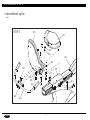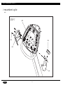
1
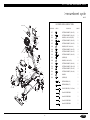
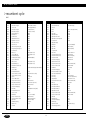
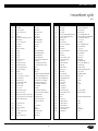
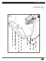
O W N E R ’ S
M A N U A L
C Y C L E S
Table of Contents
1.0)
1.1)
1.2)
2.0)
2.1)
2.2)
3.0)
3.1)
3.2)
3.3)
4.0)
4.1)
4.2)
4.3)
4.4)
4.5)
5.0)
5.1)
5.2)
6.0)
6.1)
6.2)
6.3)
6.4)
6.5)
6.6)
IMPORTANT SAFETY INSTRUCTIONS
Read and Save These Instructions
Setting Up the Cycle
Installation Requirements
Preventative Maintenance and Cleaning Tips
1
1
1
1
USING MANAGER PREFERENCE MODE
Using C Safe
Setting Up Fit Connexion™
2
2
2
ADJUSTING THE SEAT HEIGHT
Upright Seat Height
Recumbent Seat Height
Recumbent Lumbar Support
3
3
3
3
USING THE CYCLE OR RECUMBENT
Console Description
Manual Operation
Operating Level Based Programs
Heart Rate Control
Constant Watts
4
4
4
5
5
EQUIPMENT SPECIFICATIONS
MX-R5
MX-U5
6
7
PARTS AND ASSEMBLY
MX-R5 Exploded View
Parts List
Assembly Instructions
MX-U5 Exploded View
Parts List
Assembly Instructions
9
11
12
14
23
24
26
1) Important Safety Instructions
R E A D A N D S AV E T H E S E I N S T R U C T I O N S
SETTING UP THE CYCLE
• This Cycle is intended to for commercial use
Assembly instructions have been provided with your Cycle. For your safety, please read and follow each of the steps in the assembly guide. To obtain a copy of the assembly guide, please
contact MATRIX FITNESS SYSTEMS.
• To insure your safety and protect the equipment, read all instructions before operating the
MATRIX Cycle.
When using an electrical product, basic precautions should always be followed, including
the following:
1.1
DANGER To reduce the risk of electric shock:
I N S TA L L AT I O N R E Q U I R E M E N T S
Your MATRIX Cycle is designed to be self contained and does not require a power
supply to operate.
• Always unplug this equipment from the electrical outlet immediately after using and
before cleaning.
Your MATRIX Cycle is self-generating (requiring no external power source) and must be pedaled to power up the console.
Fit ConnexionTM requires a 9 volt battery and a 110 volt power supply to operate the monitor.
Use only the power supply provided by the manufacturer, please contact MATRIX FITNESS for
a replacement.
WARNING To reduce the risk of burns, fire, electrical shock or injury to persons that may be
associated with using this product:
• An appliance should never be left unattended when plugged in. Unplug from outlet when
not in use and before putting on or taking off parts.
• This product must be used for its intended purpose described in this Owner’s Guide. Do not
use other attachments that are not recommended by the manufacturer. Attachments may
cause injury.
• To prevent electrical shock, never drop or insert any object into any opening.
• Do not remove the side covers. Service should only be done by an authorized service technician.
• Never operate the Cycle with the air openings blocked, Keep the air openings clean, free of
lint, hair and the like.
• Never operate product if it has a damaged cord or plug, if it is not working properly, if it has
been damaged, or immersed in water. Return the appliance to a service center for examination
and repair.
• Do not carry this appliance by supply cord or use cord as handle.
• Keep any power cord away from heated surfaces.
• Keep hands and loose clothing away from moving parts.
• Close supervision is necessary when Cycle is used by or near children, invalids, or disabled persons.
• Do not use outdoors.
• Do not operate where aerosol (spray) products are being used or where oxygen is being
administered.
• To disconnect, turn all controls to the off position, then remove plug from outlet
• Connect this Cycle to a properly grounded outlet only.
CAUTION Use of the wrong power supply may cause damage to your Cycle and/or entertain-
CAUTION If you experience chest pain, nausea, dizziness or shortness of breath, STOP exercis-
• Maintain a clean area around equipment free from dust and dirt.
ment device.
Locate a level stable surface to position Cycle. The Cycle has four leveling feet located under
the foot support. If your Cycle wobbles in the location where you intend to use it, loosen the
lock nut on the adjusting foot and adjust the feet until stable. Once level, lock the adjusting
feet by tightening the lock nut to the frame.
1.2
P R E V E N TAT I V E M A I N T E N A N C E A N D C L E A N I N G T I P S
Preventative maintenance and daily cleaning will prolong the life and look of your Matrix fitness equipment.
Please read and follow these tips.
• Position the equipment away from direct sunlight. The intense UV light can cause discoloration
of plastics.
• Locate your equipment in an area with cool temperatures and low humidity.
• Clean with a soft 100% cotton cloth.
• Clean with non-ammonia based cleaners.
• Wipe seats, handles, heart rate grips, and handlebars clean after each use.
• Do not pour liquids directly onto your equipment. This can cause damage to the equipment
and in some cases electrocution.
• Check pedal safety straps weekly for wear.
• Adjust leveling feet when equipment wobbles or rocks.
ing immediately and consult a physician before continuing.
1
2) Using Manager Preference Mode
2.0
USING MANAGER PREFERENCE MODE
UNIT 1
Your MATRIX Cycle is designed to allow you to customize settings for your preferences and
diagnostics. The Manager Preference Mode can only be accessed while the Cycle is powered
up. Follow the instructions to adjust the Cycle computer for your desired settings.
STEP 1
Power up the Cycle and Hold the UP and DOWN arrow keys for 3 seconds. The word
Manager will appear in the alphanumeric window and will enter into the Manager
Preference Setting automatically after 3 seconds. Continue to pedal until finished.
STEP 2
Select information you would like to view or change from the following list, by using
the UP or DOWN arrows. Press ENTER to select.
CPU
CSAFE IN
CSAFE OUT
UNIT 2
CSAFE IN
CSAFE OUT
2.2
UNIT 3
CSAFE IN
SETTING UP FIT CONNEXION™
Fit ConnexionTM
Manager preference mode will allow you to view and set the following.
DISPLAY
Manager
CODE: INFORMATION
USER DEFINABLE
DEFAULT VALUE
MIN.
MAX.
P0: Maximum program time
Y
95 min
5
95
P1: Default time
Y
20 min
5
95
P2: Default level
Y
L1
L1
L20
P3: Default weight
Y
150 lbs
80 lbs
400 lbs
P4: Speed
Y
Miles
Miles
KM
P5: Machine
Y
BI
BI
RE, EL
P6: TV IR
Y
On
On
Off
P7: Cardio Entertainment
Y
On
On
Off
P8: Accumulated Distance
Your equipment is preset to offer you the maximum benefit of your desired entertainment offering.
Whether it is FIT CONNEXIONTM or other CSAFE entertainment packages, Matrix makes it easy
to connect. Look on the back of the console and locate the receptacle labeled ENTERTAINMENT.
This port is specific for audio and visual entertainment devices. CSAFE ready products can plug
in and utilize the volume, channel and headphone connector
When installing Fit Connection make sure you are using the power cord supplied with your
package. Other power cords could cause malfunctions with your product.
Assemble the Fit Connection bracket by following the instructions supplied in your package.
Make sure you feed the power cord and coaxial cable through the round hole at the top of the
bracket. Insert the monitor and fasten with the screw provided.
P9: Accumulated Time
P10: Software Version
STEP 3
STEP 4
STEP 5
Use UP or DOWN arrows to increase or decrease values.
Press START to save and enter selected values and exit to STEP 2.
Exit by pressing Start. Screen will reset to Start up.
2.1 USING CSAFE s
Connect the coaxial cable and the power cord to the monitor.
Take the Fit ConnexionTM audio cord and plug it into the audio out on the back side of the monitor. The RJ45 needs to now be plugged into the Jack labeled Entertainment. This cord provides
the audio to your headphones.
At the front base of the unit you will see the Fit Connexion TM coaxial cable and power supply connectors. Connect the coaxial cable and the power supply. Turn the monitor on and see if it has power.
Follow the instructions provided with your monitor to select language and input device options.3 . 0
Matrix is the leader in entertainment availability. On the back of the console are three RJ45
receptacles. They are marked CSAFE IN, CSAFE OUT, and ENTERTAINMENT.
Use the CSAFE IN to plug in any CSAFE device using the RJ45 connector CSAFE OUT allows
CSAFE products to be daisy chained together from one unit to the next. The connection is as follows;
2
3) Adjusting the Seat Height
3.0
A D J U S T I N G T H E S E AT H E I G H T
Your MATRIX Cycle is designed for ease of use. We have incorporated seat height adjustments
that are easily located and simple to adjust.
3.1
U P R I G H T S E AT H E I G H T
To adjust the seat height on the Upright Cycle, locate the red pull pin before you mount the
Cycle. To lower the seat down, pull the red knob while holding the seat with the other hand
and slide up or down accordingly. To adjust seat height up, simply raise the seat to desired
position. Our automatic seat lock will set. Make sure you are not seated when you pull the
knob or pull seat up.
3.2
R E C U M B E N T S E AT H E I G H T
To adjust you’re seat height on the Recumbent Cycle locate the red lever under the right side
of the seat before you mount the Cycle. Place your right hand on the red adjustment handle
under the right side of the seat. Place feet on the ground while seated and slide forward if
needed. Place feet on pedals, gently lift lever under the right side of the seat. Using legs slowly push and slide the seat up or down to desired position. Release lever and allow to lock into
place.
3.3 RECUMBENT LUMBAR SUPPORT
The red knob on the side of the seat is for adjusting the lumbar support. To adjust, simply turn
the knob located on the back rest. Turn the knob forward to increase support and backward to
decrease support until desired comfort has been achieved.
3
4) Using the Cycle or Recumbent
4.1
CONSOLE DESCRIPTION
STEP 1 Select Manual program button on left of panel.
NOTE
Press Enter or wait 5 seconds.
Selecting START will start program.
STEP 2 Select Time by using the UP or DOWN arrow keys. When finished
NOTE
Press Enter or wait 5 seconds.
Selecting START will start program.
STEP 3 Select Level by using UP or DOWN arrow keys. You can change the level at any time
during workout. When finished,
Press Enter or Wait 5 seconds.
NOTE Selecting START will start program.
STEP 4 Select Weight by using the UP or DOWN arrow keys.
Press START or ENTER to begin workout.
Display
TIME
Starting 3
Starting 2
Starting 1
PROGRAMS Simple program view and selection buttons. Matrix Cycles feature seven programs.
START / QUICK START One touch Quick Start and Start any time during preference selection.
UP / DOWN Easy information and level selection.
ENTER / SELECT SCREEN / RESET This multi-function button enters information when setting up
programming options, toggles information displayed and if held down for 5 seconds resets
the Cycle to Start-up mode.
DISPLAY VIEW These three buttons allow the user to customize the way the unit’s lights are displayed.
ENTERTAINMENT Control the CHANNEL and VOLUME of your attached TV or entertainment
system. (Must have Fit ConnexionTM or entertainment source connected)
HEAD PHONE JACK Located at the base of the console, just plug in a headset and use the
ENTERTAINMENT buttons to adjust VOLUME. (Must have Fit ConnexionTM or entertainment
source connected)
4.2
M A N U A L O P E R AT I O N
MATRIX design makes using the programs as easy as one touch of a button.
QUICK START Start pedaling and press QUICK START to begin workout.
4.3
O P E R AT I N G L E V E L B A S E D P R O G R A M S
Your MATRIX Cycle offers versatile programs to keep the user motivated.
The following Instructions will guide you through simple steps to select INTERVALS, ROLLING,
FAT BURN, and RANDOM programs.
STEP 1 Select the program button on left of panel.
NOTE
Press ENTER or wait 5 seconds.
Selecting START will begin program.
STEP 2 Select Time by using the UP or DOWN arrow keys. When finished
NOTE
Press ENTER or wait 5 seconds.
Selecting START will begin workout.
STEP 3 Select Level by using UP or DOWN arrow keys. You can change the level at any time
during workout. When finished,
Press ENTER or Wait 5 seconds.
NOTE Selecting START will begin workout.
STEP 4 Select Weight by using the UP or DOWN arrow keys.
Press START or ENTER to begin workout.
Display
MANUAL MODE allows you enter desired time, level, and weight.
4
4) Using the Cycle or Recumbent
TIME
Starting 3
Starting 2
Starting 1
P O L A R TA R G E T H E A RT R AT E Z O N E
HR BEATS
PER MINUTE
220
200
180
4.4
H E A R T R AT E C O N T R O L
160
140
For your convenience, MATRIX FITNESS CYCLES come standard with digital contact heart rate
sensors and POLAR telemetry compatible.
120
100
Locate the metal sensors on the handrail of the Cycle. Notice there are two separate pieces of
metal on each grip. You must be making contact on both pieces of each grip to get an accurate heart rate reading. You can grab these sensors in any program to view your current heart
rate located in the lower left hand window marked Heart Rate.
80
AGE
NOTE
STEP 2
NOTE
STEP 3
NOTE
STEP 4
25
H E AV Y
Heart Rate Program
Follow these easy Steps to enter into the Heart Rate Program.
STEP 1
20
4.5
30
35
40
M O D E R AT E
45
50
55
60
65
LIGHT
C O N S TA N T WAT T S
Select TARGET HR program button on left of panel.
Press Enter or wait 5 seconds.
Selecting START will start program.
Constant Watts program is a unique program that allows you to vary your cadence or RPM and
the Cycles resistance will adjust accordingly to your selected goal. The quicker you pedal the
less resistance for the goal selected.
Select Time by using the UP or DOWN arrow keys. When finished
Press Enter or wait 5 seconds.
Selecting START will start program.
Follow these easy Steps to enter into the Constant Watts Program.
Using the following chart, select Target Heart Rate by using UP or DOWN arrow keys.
You can change the Target Heart Rate at any time during workout. When finished,
Press Enter or Wait 5 seconds.
Selecting START will start program.
NOTE
Select Weight by using the UP or DOWN arrow keys.
Press START or ENTER to begin workout.
Display
TIME
Starting 3
Starting 2
Starting 1
STEP 3
STEP 1
STEP 2
NOTE
NOTE
STEP 4
5
Select CONSTANT WATTS program button on left of panel.
Press Enter or wait 5 seconds.
Selecting START will start program.
Select Time by using the UP or DOWN arrow keys. When finished
Press Enter or wait 5 seconds.
Selecting START will start program.
Select Constant Watts goal by using UP or DOWN arrow keys. You can change the
watts target at any time during workout. When finished,
Press Enter or Wait 5 seconds.
Selecting START will start program.
Select Weight by using the UP or DOWN arrow keys.
Press START or ENTER to begin workout.
Display
TIME
Starting 3
Starting 2
Starting 1
5) Equipment Specifications
>recumbent cycle
MX-R5
S P E C I F I C AT I O N S
Product Name
Foot Print
Weight
Max User Weight
Frame Construction
Self Contained
Resistance Type
Resistance Levels
R5
49"H x 62"L x 25"W
132 lbs
400 lbs = 181 kg
Aluminum/Steel
Yes
Generator
20
PROGRAMS
One Button Quick Start
Random (20 profiles)
Target Heart Rate
Interval
Constant Watts
Rolling
Fat Burn
Yes
Yes
Yes
Yes
Yes
Yes
Yes
H E A R T R AT E
Polar Telemetry
Contact Heart Rate
Yes
Yes
E N T E R TA I N M E N T R E A D Y
Volume Control
Channel Control
Display View Control
Coaxial Cable Connection
Acc TV Power Connection
Monitor Mount
IR Port
Head Phone Jack yes
MACHINE WEIGHT
SIZE
132 lbs
inches = 49” x 62” x 25”
60 kg
cm = 128.5 x 157.5 x 63.5
6
Yes
Yes
3 Views
Yes
Yes
Yes
Yes
5) Equipment Specifications
> upright cycle
MX-U5
S P E C I F I C AT I O N S
Product Name
Foot Print
Weight
Max User Weight
Frame Construction
Self Contained
Resistance Type
Resistance Levels
U5
57"H x 44"L x 25"W
106 lbs
400 lbs = 181 kg
Aluminum/Steel
Yes
Generator
20
PROGRAMS
One Button Quick Start
Random (20 profiles)
Target Heart Rate
Interval
Constant Watts
Rolling
Fat Burn
Yes
Yes
Yes
Yes
Yes
Yes
Yes
H E A R T R AT E
Polar Telemetry
Contact Heart Rate
Yes
Yes
E N T E R TA I N M E N T R E A D Y
Volume Control
Channel Control
Display View Control
Coaxial Cable Connection
Acc TV Power Connection
Monitor Mount
IR Port
Head Phone Jack
MACHINE WEIGHT
SIZE
106 lbs
inches = 57” x 44” x 63.5”
48 kg
cm = 144.8 x 111.8 x 25
7
Yes
Yes
3 Views
Yes
Yes
Yes
Yes
Yes
T H I S PA G E I N T E N T I O N A L LY B L A N K
6) Parts & Assembly
>cycles
MX-R5 and MX-U5
T H I S PA G E I N T E N T I O N A L LY B L A N K
6.1) MX-R5 Exploded View
>recumbent cycle
MX-R5
FASTENERS AND ASSEMBLY TOOLS
WATER BOTTLE
TV
REFERENCE
SKETCH
DESCRIPTION
QUANTITY
N10
C27
C28
TV RACK
AN1
P03
C17
BUTTON HEAD BOLT (M8 x 15L)
6
C20
BUTTON HEAD BOLT (M4 x 10L)
3
C24
WASHER (8.2x18.0x1.4t(BED)
2
C30
BUTTON HEAD BOLT (M8 x 50L)
2
D37
BUTTON HEAD BOLT (M8 x 25L)
2
D39
WASHER (SW5 5.1x9.3x1.3t)
2
D43
BUTTON HEAD BOLT (M8 x 15L)
4
D56
BUTTON HEAD BOLT (M8 x 15L)
3
D44
BUTTON HEAD BOLT (M8 x 50L)
4
C31
SCREW (M8)
2
D46
WASHER (8.2x18.0x1.5t)
4
F05
BUTTON HEAD BOLT (M8 x 20L)
6
F06
BUTTON HEAD BOLT (M10 x 20L)
5
N25
BUTTON HEAD BOLT (M5 x 12L)
4
C26
BUTTON HEAD BOLT (M4 x 38L)
1
C27
WASHER
1
C28
SCREW (M4)
1
OPEN WRENCH (#13)
1
OPEN WRENCH (#17)
1
PHILLIPS DRIVER (4.5 x 50mm)
1
5mm ALLEN WRENCH
1
4mm ALLEN WRENCH
1
5mm ALLEN WRENCH
1
6mm ALLEN WRENCH
1
C26
P04
P01
AC3
P23
N25
C17
C17
C20
C12
D11
AC4
AC2
C23
T08
T09
C11
D13
AC1
Q03
C31
D43
C24
C24
D55
C30
AB1
A02
F02
P07
A01
P22
D46
D55
D44
D37
D56
AD5
F05
D04
F01
T08
T09
F06
11
6.2) Parts List
>recumbent cycle
MX-R5
NO.
AG1
AN1
AN2
AN2
AU1
D13
D23
D25
Q01
Q02
R01
R04
R05
T01
AB1
AC1
AC2
AC3
AC4
AD1
AD2
AD6
AZ1
C01
C10
C11
C12
C13
C14
C17
C18
C19
C20
C21
C22
C23
C24
C25
C30
C31
C32
D04
D11
DESCRIPTION
Hand Pulse Grip Set
Console Set
Hand Pulse Grip Set
Hand Pulse Grip Set
Tension Wheel Set
Back Pad Set
Seat Roller Set
Adjustable Roller Set
Right Side Cover Set
Left Side Cover Set
Drive Axle Set
Slide Bearing Housing Set
Fixing Bearing Housing Set
Pedal Axle Set
Frame Set
Console Mast Set
Front Handlebar Set
TV Bracket (with Cables)
Console Fixed Plate
Slide Seat Set
Back Pad Mast Set
Back Pad with Lumbar Set
Hardware Kit
Console Mast
Front Handlebar Axle
Console Lower Cover-RH
Console Lower Cover-LH
Spacer
Console Mast Sleeve
Screw, Inner Hex Socket
Rivet (Brass Inserts Nut)
Screw, Oval Hex Socket
Screw, Round Tapping
Fixed Nut
Front Handlebar Cover
Console Cover
Flat Washer
Screw, Oval Hex Socket
Screw, Round Hex Socket
Nylon Nut
2-E.ND Round Key
Adjust Lever
Seat Pad
S P E C I F I C AT I O N
NO.
RB50 (w/HP) w/Texture
RB50 (English-Metric)
CB32 (w/Texture)
CB32 (w/o Texture)
RB50
RB50
RB50
RB50
RB50
RB50
RB50
CB32
CB32
CB32
RB50 (Metal Color)
RB50 (Metal Color)
PVC
MATRIX R5(RB50)
D12
D18
D21
D23
D24
D25
D26
D29
D30
D31
D32
D33
D34
D35
D36
D37
D38
D39
D40
D41
D43
D44
D46
D48
D51
D52
D53
D54
D55
D56
D57
F01
F02
F03
F04
F05
F06
H01
H02
H03
H04
H05
H06
RB50 (Metal Color)
RB50 (Metal Color)
Include Hand Tools (Purple Round Sticker)
SS41
ABS (Knurled on Surface)
ABS
20x26x15L
Nylon
M8x1.25Px15L
ALS7-8125-3.8 (0.5-3.8)
M8x1.25Px20L
4x10L
AN04 (M20x1.0Px6t) (Bed)
PVC
Nylon
8.2x_18x1.4t (Bed)
M8x1.25Px15L
M8x1.25Px50L (30L)
M8x1.25P (Bed)
6x6x16L
SS41
12
DESCRIPTION
Seat Pad Fixed Plate
U Sleeve
Knob
Roller
Roller Axle
Adjustable Roller
Adjustable Roller Axle
Adjustable Positioning Board
Located Block
Adjustable Spring
Handlebar
Nylon Nut
Nylon Nut
C Clip-External
Settle Bolt
Screw, Round Hex Socket
Screw, Round Hex Socket
Screw, Plain Head
Screw, Round Tapping
Spiral Shells Axle Cover
Screw, Inner Hex Socket
Screw, Oval Hex Socket
Arc Washer
Screw, Round Tapping
Front Fixed Board for Cable
Steel Cable Fixed Bracket
Foam Grip
Foam Grip
Spring Washer
Screw, Shallow Hex Socket
End Cap
Rear Stabilizer Set
Front Stabilizer-RH Set
Front Stabilizer-LH Set
Adjustable Foot Pad
Screw, Oval Hex Socket
Screw, Oval Hex Socket
Slide Rail
Rail Fixed Plate
Screw, Round Tapping
Rail End Cap
Stop Wheel Shaft
Seat Pad Stopper Roller
S P E C I F I C AT I O N
SPC (Zinc Plating)
Nylon + Fiber (Red #1797)
POM
SS41
POM
SS41
SPC
S45C
Long Pearl #4 (Red)
M6x1.0P (Bed)
M8x1.25P (Bed)
S-10
M12x1.75Px12.0L
M5x0.8Px25L
M6x1.0Px30L(15L)
M5x0.8Px10L
M5x0.8Px12L
ABS
M8x1.25Px15L (Bed)
M8x1.25Px50L
8.2x18x.15t
3x12L
SPC
SPC
25.0x31.0x240L
PVC Sleeve (Red #1797)
SW8 8.0x17.0x1.5t
M8x1.25Px15L (Bed)
PVC Black
CB32
CB32
CB32
No Turn
M8x1.25Px20L (Bed)
M10x1.5Px20L
AL
SPC
3x10L
ABS
SS41(Zinc Plating)
PU
6.2 Parts List
>recumbent cycle
MX-R5
NO.
DESCRIPTION
H07
H08
H09
H11
H12
H13
L01
L02
L03
L04
N10
N15
N15
N15
N15
N20
N21
N22
N22
N23
N26
N27
P01
P05
P06
P07
P10
P12
P13
P18
P19
P20
P22
P23
P26
Flat Washer
Screw, Oval Head
Screw, Oval Hex Socket
Bolt
Flat Washer
Hexagon Socket Headless Set Screws
Mobile Wheel
Screw, Oval Hex Socket
Flat Washer
Nylon Nut
Water Bottle Holder
Overlay
Overlay
Overlay
Overlay
2-in-1 Polar Receiver
Sensor Grip
Heartbeat Sensor Plate
Heartbeat Sensor Plate
End Cap, Hand Pulse Grip
Screw, Round Tapping
Hex Nut
Console Cable
Connecting Cable of Controller
Power Resistance
Hand Pulse Cable
CONSOLE MAST CABLE
TV Power Cable
TV Power Cable
Ferrite Cord
Power Transferred Cable
E-Port Control Board
Heartbeat Sensor Rail Connecting Cable
Connecting Cable for Console Heart Rate
Earphone Extended Cable
Q03
Q05
Q06
Q07
R15
R16
R17
Console Mast Cover
Crank Cover
Screw, Oval Tapping
C-Clip
Screw, Round Hex Socket
Flat Washer
Screw, Oval Hex Socket
S P E C I F I C AT I O N
NO.
_5x_16x1.0t
M4x0.7Px10L
M8x1.25Px50L(18L)
M5x0.8Px10L
_6.5x_13x1.5t
M5x0.8Px15L
NYLON+30%FIBER
M8x1.25Px70L(12L)
8.2X16x1.0t
M8x1.25P
ABS
MX U5/R5/E5 (Holland)
MX U5/R5/E5 (Germany)
MX U5/R5/E5 (Italy)
MX U5/R5/E5 (U.S.A.)
POLAR 39021539.00 (RB59-P12A)
CB32-N21F
101.5x32 (SUS304) (w/ Texture)
101.5x32 (SUS304) (w/o Texture)
Nylon
M3x0.5Px35L
M3x0.5P
1300(XAP-07V-1+H6657P-2+SMR-08V-B)
750(3.96-5P VH WHITE+HL20P-03)
400W10_-200(3.96-4P WHITE VH)
700 (H6657R1-2+110* F END*2)
800(SMP-08V-BC+H6657P1-8)
1250 (XAP-02V-1+SMR-02V-B)
1250 (RG-6)X2
FH0900B-2
1000 (XAP-02V-1+H6657R1-2)
w/PCB Board-DC Bracket & Adapter
1360 (H6657P-2)X4
800 (H6657R1-2)X4
185 (3.5 3-D Earphones+
Microphone F*Base 3P)
PVC
PVC (Anthracite)
_4x12L
WUSN-5030
M5x0.8Px10L (Bed)
_5.2x_13x1.5t
M6x1.0Px12L
13
R18
R19
R20
S01
S01
S02
S03
S04
S05
S06
S07
S08
S09
S11
S12
S14
T07
T08
T09
T13
T15
T17
T18
T19
U04
U05
U06
U07
U08
U09
U11
U12
V01
V02
X01
Z02
Z03
Z04
Z05
Z06
Z07
DESCRIPTION
Flat Washer
Ploy V Belt
Ploy V Belt
Generator (CB32-KT/RB50-KT)TW Line
Generator (JM07-AM1A)USA Line
Eye Hook Screw
Flat Washer
Nut, Hex Head
Hook Cover for Eye Bolt
Nylon Nut
Flat Washer
Control Board (JE07002)
Hex Nut
Flat Washer
Screw, Round Hex Socket
Screw, Round Tapping
Ball Bearing
Pedal & Pedal Strap
Pedal Strap
Right Crank Nut
Front Spacer
Flat Washer
Spacer Tight Nut
Large Screw, Oval Head
Pulling Adjustable Plate
Ball Bearing
C Clip Internal
Ball Bearing
C Clip-External
C Clip-External
Tension Wheel Spring
Screw, Round Hex Socket
Rail Decal
Decal
Carton(1) Set
L-Key Hex Wrench
L-Key Hex Wrench
Open End Wrench
Screw Driver, Cross Type
Open End Wrench
T Type Wrench
S P E C I F I C AT I O N
_6.2x_20x2.0t (HRC47-52)
500-J6 (Carlisle)
440-J8 (Carlisle)
_190 CE CB/RB MX/600 Series
_190 NO CE MX/600 Series (JM07-AMIA)
1/4”-20UNCx70L Eye Hole 10
_10.2x_15x1.5t
3/8”-26UNF
1.6t SPC (Bed)(CB32-S05D)
1/4"-20UNC (Bed)
_1/4”x_15x1t
U5-R5-E5-H002 (JE07002)
3/8”-26UNCx4H
_5.3x_10x1.0t
M5x0.8Px12L
M5x0.8Px8L
6205ZZ (BR6205ZZ)
EX-13 1/2 BR-”MATRIX” logo
PU (CB32-T09B)
SS41 (Zinc Plating)
Powder Metallurgy (CB32-T15I)
_32x_25.3x1.0t
SS41(ZINC PLATING)
M4x0.7Px8L
2t SPC
6206ZZ
R-62
6204ZZ
S-30
S-20
Zinc Plating SWPB
M5x0.8Px10L (Bed)
Matrix (Except Italy) (CB32-V04B)
4MM
5MM
#13
4.5*50
#15#17x325L
5mm
6.3) Assembly Step 1
>recumbent cycle
MX-R5
F03
STEP 1
F02
AD1
F05 (Green)
14
6.3) Assembly Step 2
>recumbent cycle
MX-R5
STEP 2
F01
AD1
FD6
15
6.3) Assembly Step 3
>recumbent cycle
MX-R5
STEP 3
T08
T09
16
6.3) Assembly Step 4
>recumbent cycle
MX-R5
STEP 4
AC1
Q03
C31
C24
C24
C30
17
6.3) Assembly Step 5
>recumbent cycle
MX-R5
STEP 5
D13
D11
D43
D55
AB1
AD2
P07
AD1
P22
D46
D55
D37
D44
D04
D56
AD5
18
6.3) Assembly Step 6
>recumbent cycle
MX-R5
STEP 6
N10
N38
N29
AN1
P01
P23
P01
P23
N25
AC4
C17
AC2
19
6.3) Assembly Step 7
>recumbent cycle
MX-R5
STEP 7
AN1
C20
C23
C12
C11
20
6.3) Assembly Step 8
>recumbent cycle
MX-R5
TV
STEP 8
TV RACK
C27
C28
P03
C26
P04
AC3
C17
C23
21
T H I S PA G E I N T E N T I O N A L LY B L A N K
6.4) MX-U5 Exploded View
>upright cycle
MX-U5
FASTENERS AND ASSEMBLY TOOLS
N10
REFERENCE
SKETCH
DESCRIPTION
QUANTITY
AN1
J04
ADJUST PEDAL
4
J06
BUTTON HEAD BOLT (M10 x 20L)
5
J05
BUTTON HEAD BOLT (M8 x 20L)
6
C16
BUTTON HEAD BOLT (M8 x 50L)
1
D08
WASHER
4
D07
BUTTON HEAD BOLT (M8 x 20L)
4
C12
BUTTON HEAD BOLT (M8 x 50L)
2
C13
WASHER
2
C14
SCREW (M8)
2
G08
BUTTON HEAD BOLT (M8 x 50L)
4
G09
WASHER
4
G10
SCREW (M8)
4
C15
BUTTON HEAD BOLT (M4 x 45L)
4
C16
BUTTON HEAD BOLT (M8 x 50L)
1
C17
WASHER
1
C18
SCREW (M4)
1
OPEN WRENCH (#13)
1
PHILLIPS DRIVER (5.5 x 75mm)
1
5mm ALLEN WRENCH
1
6mm ALLEN WRENCH
1
C11
C16
C17
C18
P06
P02
P03
AG1
N25
AC2
C15
C06
G10 G09
P01
P02
C08
C15
P03
C07
C08
C04
AC1
D08
Q03
D07
D03
AD1
J03
C14
T09
D05
C13
C12
T08
C19
J02
T09
J04
T08
J04
J06
J01
23
6.5) Parts List
>upright cycle
MX-U5
NO.
AG1
AG1
AN1
AN1
AN1
AN1
AN2
AN2
AU1
Q01
Q02
R01
R04
R05
T01
AB1
AC1
AC2
AC5
AD1
AZ1
B23
B24
B25
B28
C04
C06
C07
C08
C12
C14
C15
C19
C22
D03
D04
D05
D06
D07
D08
D09
D10
D11
DESCRIPTION
Handlebar Set
Handpulse Grip Set
Console Set
Console Set
Console Set
Console Set
Hand Pulse Grip Set
Handpulse Grip Set
Tension Wheel Set
Right Side Cover Set
Left Side Cover Set
Drive Axle Set
Fixing Bearing Housing Set
Slide Bearing Housing Set
Pedal Axle Set
Main Frame
Console Mast
TV Bracket (With Cables)
TV-Support Bracket
Seat Mast
Hardware Kit
C Clip
Screw, Oval Head
Nylon Nut
C Clip
Outer Tube Of Console
Console Lower Cover-Lh
Console Lower Cover-Rh
Console Cover
Screw, Round Hex Socket
Nylon Nut
Screw, Round Tapping
Screw, Round Hex Socket
Spring Washer
Seat Mast Bushing
Lower Bushing Of Seat Mast
Seat Post Adjusting Pin Set
Seat Pad
Nylon Nut
Spring Washer
Screw, Plain Head
Bushing
Screw, Oval Head
S P E C I F I C AT I O N
NO.
CB32 (w/HP) w/Texture
CB32 (w/HP) w/o Texture
CB32 (English-Metric)
CB32 (Netherlands-Metric)
CB32 (Germany-Metric)
CB32 (Italy-Metric)
CB32 (w/Texture)
CB32 (w/o Texture)
CB32
CB32
CB32
CB32
CB32
CB32
CB32
CB32 (Anthracite)
CB32 (Anthracite)
Matrix U5 (CB32)
Matrix U5 (CB32)
CB32 (Halftone Printing)
Include Hand Tools (Purple Round Sticker)
WUSN-4039
M5x0.8Px12L (Bed)
M5x0.8P
USN-4043
CB32-C04
ABS (CB32-C06B)
ABS (CB32-C07C)
NYLON
M8x1.25Px50L (30L)
M8x1.25P (Bed)
4x12L
M8x1.25Px60L
SW8 8.2x15.4x2t
Nylon
Nylon (Iron-Tin Color)
M16 (CB32-D05C)
Air Cushion (CB32-D06M)
M8x1.25P (Chromate Treatment)
M8 (Zinc Plating)
M4x0.7Px10L
POM (JS001-11)
M6x1.0Px50L (10L)
24
DESCRIPTION
D12
D15
G08
J01
J02
J03
J04
J05
J06
L01
L02
L03
L04
N10
N15
N15
N15
N15
N20
N21
N22
N22
N23
N26
N27
P01
P02
P03
P04
P05
P06
P11
P16
P18
Nylon Nut
Nylon Nut
Screw, Inner Hex Socket
Rear Stabilizer
Front Stabilizer-RH
Front Stabilizer-LH
Adjustable Foot Pad
Screw, Oval Hex Socket
Screw, Oval Hex Socket
Mobile Wheel
Screw, Oval Hex Socket
Flat Washer
Nylon Nut
Watter Bottle Holder
Overlay
Overlay
Overlay
Overlay
2-in-1 Polar Receiver
Sensor Grip
Heartbeat Sensor Plate
Heartbeat Sensor Plate
End Cap, Hand Pulse Grip
Screw, Round Tapping
Hex Nut
Console Cable
E-Port Power Connecting Cable
E-Port TV Signal Cable
Connecting Cable Of Controller
Power Resistance
Hand Pulse Cable
Adapter
Ferrite Cord
Earphone Extended Cable
P19
P20
P21
P23
P25
P37
Q01
Q02
Power Transferred Cable
E-Port Control Board
TV Signal Cable
Console Mast Cable
TV Power Cable
End Protect Bushing
Right Side Cover
Left Side Cover
S P E C I F I C AT I O N
M6x1.0P (Chromate Treatment)
M4x0.7P
M8x1.25Px15L
CB32
CB32
CB32
M8x1.25Px20L (Bed)
M10x1.5Px20L
NYLON+30%FIBER
M8x1.25Px70L(12L)
8.2x18x1.4t (Bed)
M8x1.25P (Bed)
ABS
MX U5/R5/E5 (U.S.A.)
MX U5/R5/E5 (Holland)
MX U5/R5/E5 (Germany)
MX U5/R5/E5 (Italy)
POLAR 39021539.00 (RB59-P12A)
CB32-N21F
101.5x32 (SUS304) (w/Texture)
101.5x32 (SUS304) (w/o Texture)
Nylon
M3x0.5Px35L
M3x0.5P
1050(XAP-07V-1+H6657R1-8+SMR-08V-B)
350 (XAP-02V-1+SMP-02V-BC)
350(5C-2V+5C-2V)
600(3.96-5P+HL20P-03)
400W10_-200(3.96-4P White VH)
700 (H6657R1-2+110xF)
5C-2V (w/Nut)
FH0900B-2
185(3.5 3-D Earphones+
Microphone F*Base 3P)
1200(XAP-02V-1+H6657R1-2)
w/PCB Board- DC Bracket & Adapter
1250(RG-6)X2 (w/Adapter x1)
900 (SMP-08V-BC+H6657P1-8)
1250 (SMR-02V-B)x1
(KSS) EP-1113(BUY-OUT)
ABS
ABS
6.5) Parts List
>upright cycle
MX-U5
NO.
Q03
Q04
Q05
Q06
Q07
Q08
Q09
R06
R07
R08
R09
R10
R11
R12
R13
R14
R15
R16
R17
R18
R19
R20
S01
S01
S01
S02
S03
S04
S05
S06
S07
S08
S09
S10
S11
T07
T08
T09
T13
T15
T17
T18
T19
DESCRIPTION
Console Mast Cover(Black)
Protecting Cover For Seat Mast
Crank Cover
E-Port Fixing Plate
Screw, Oval Head
Screw, Oval Head
Connecting Plate For Side Cover
Tight Nut
2-End Round Key
Ball Bearing
Ball Bearing
One-Way Bearing
C Clip-Internal
C Clip-Internal
C Clip-External
C Clip-External
Screw, Round Hex Socket
Flat Washer
Screw, Oval Hex Socket
Flat Washer
Ploy V Belt
Ploy V Belt
Generator (CB32-KT/RB50-KT)TW Line
Generator-ID Line
Generator (JM07-AM1A) USA Line
Eye Hook Screw
Flat Washer
Nut, Hex Head
Hook Cover For Eye Bolt
Nylon Nut
Flat Washer
Control Board (JE07002)
Hex Nut
Screw, Round Hex Socket
Flat Washer
Ball Bearing
Pedal & Pedal Strap
Pedal Strap
Right Crank Nut
Front Spacer
Flat Washer
Spacer Tight Nut
Large Screw, Oval Head
S P E C I F I C AT I O N
NO.
PVC
PVC
PVC (Anthracite)
ABS
M4x0.7Px15L (Bed)
M3x0.5Px14L
SPC (Zinc Plating)
AN05(M25x1.5P) (Bed)
6x6x15L
6202ZZ(BR6202ZZ)
6204ZZ
FC-25(BHF-2520)
R-47
R-35
S-20
S-30
M5x0.8Px12L
_5.2x_13x1.5t
M6x1.0Px12L
_6.2x_20x2.0t(HRC47-52)
450-J8(Carlisle)
390-J6(Carlisle)
_190 CE CB/RB MX/600 Series
_190 CE CB/RB MX/600 Series
_190 NO CE MX/600 Series (JM07-AMIA)
1/4”-20UNCx70L Eye Hole 10
_10.2x_15x1.5t
3/8”-26UNF
1.6t SPC (Bed)(CB32-S05D)
1/4”-20UNC (Bed)
_1/4”x_15x1t
U5-R5-E5-H002(JE07002)
3/8”-26UNCx4H
M5x0.8Px12L
_5.3x_10x1.0t
6205ZZ(BR6205ZZ)
EX-13 1/2 BR-”Matrix” logo
PU(CB32-T09B)
SS41(Zinc Plating)
Powder Metallurgy (CB32-T15I)
_32x_25.3x1.0t
SS41(Zinc Plating)
M4x0.7Px8L
25
U04
U05
U06
U07
U08
U09
U10
U11
U12
V04
X01
X02
Z02
Z03
Z04
Z05
Z06
Z07
DESCRIPTION
Pulling Adjustable Plate
Ball Bearing
C Clip Internal
Ball Bearing
C Clip-External
Screw, Hex Head
Hex Nut
Flexible Spring
Screw, Round Hex Socket
Decal
Carton
Styrofoam Packaging
L-Key Hex Wrench
L-Key Hex Wrench
L-Key Hex Wrench
Open End Wrench
Screwdriver, Cross Type
Open End Wrench
Assembly Guide
Assembly Guide(Console)
Owner’s Manual(Console)
S P E C I F I C AT I O N
2t SPC(SPA09509)
(BR6006ZZ)
R-55
6204ZZ
S-09
M8x1.25Px25L
M8 (Zinc Plating)
_16.0*_2.0*100.0L*25.5 (S7)
M5x0.8Px10L (Bed)
Matrix (Except Italy)(CB32-V04B)
CB32
M5
M6
M8
#13
4.5*50
#15#17x325L
E5/R5/U5/T4/T5
(ID Line Use Only)
Fairy Book (for ID Line/Matrix-CV All)
6.6) Assembly Step 1
>upright cycle
MX-U5
STEP 1
J03
AB1
J02
J05
26
6.6) Assembly Step 2
>upright cycle
MX-U5
STEP 2
AB1
J06
J01
27
6.6) Assembly Step 3
>upright cycle
MX-U5
STEP 3
T08
AB1
T08
28
6.6) Assembly Step 4
>upright cycle
MX-U5
P01
STEP 4
C04
Q03
AC1
C14
C13
C12
C19
29
6.6) Assembly Step 5
>upright cycle
MX-U5
STEP 5
D08
AD1
D07
30
6.6) Assembly Step 6
>upright cycle
MX-U5
STEP 6
AG1
G09
G10
P01
P02
P03
31
G03
6.6) Assembly Step 7
>upright cycle
MX-U5
STEP 7
N38
N29
C15
N10
C06
C08
C15
P02
P03
C07
AN1
AG1
N24
P01
32
M AT R I X
F I T N E S S
S Y S T E M S ,
I N C .
1 4 11 B R O A D W AY, N E A L B U Q U E R Q U E , N M 8 7 1 0 2
TOLL FREE 866.693.4863
FAX 5 0 5 . 2 4 2 . 4 7 2 5
w w w. m a t r i x - f i t n e s s . c o m