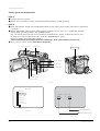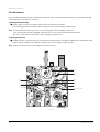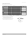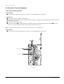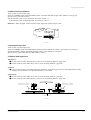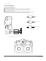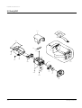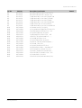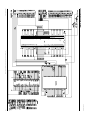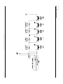
1
ELECTRONICS © Samsung Electronics Co., Ltd. MAR. 2004 Printed in Korea AD82-00048A SERVICE MANUAL This Service Manual is a property of Samsung Electronics Co .,Ltd. Any unauthorized use of Manual can be punished under applicable International and/or domestic law. DIGITAL VIDEO CAMCORDER Chassis : Delta II SCD101 SCD105 SERVICE Manual CONTENTS If you want to know additional information which is not included on this Service Manual, please refer to the SCD103 Training Manual (AD82-00031A). DIGITAL VIDEO CAMCORDER 1. Precautions 2. Alignment and Adjustments 3. Exploded View and Parts List 4. Electrical Parts List 5. Block Diagram 6. PCB Diagrams 7. Schematic Diagrams NTSC SCD101/SCD105 1. Precautions 1. Be sure that all of the built-in protective devices are replaced. Restore any missing protective shields. 2. When reinstalling the chassis and its assemblies, be sure to restore all protective devices, including : control knobs and compartment covers. 3. Make sure that there are no cabinet openings through which people--particularly children --might insert fingers and contact dangerous voltages. Such openings include the spacing between the picture tube and the cabinet mask, excessively wide cabinet ventilation slots, and improperly fitted back covers. If the measured resistance is less than 1.0 megohm or greater than 5.2 megohms, an abnormality exists that must be corrected before the unit is returned to the customer. 4. Leakage Current Hot Check (See Fig. 1-1) : Warning : Do not use an isolation transformer during this test. Use a leakage current tester or a metering system that complies with American National Standards Institute (ANSI C101.1, Leakage Current for Appliances), and Underwriters Laboratories (UL Publication UL1410, 59.7). 5. With the unit completely reassembled, plug the AC line cord directly the power outlet. With the unit’s AC switch first in the ON position and then OFF, measure the current between a known earth ground (metal water pipe, conduit, etc.) and all exposed metal parts, including : antennas, handle brackets, metal cabinets, screwheads and control shafts. The current measured should not exceed 0.5 milliamp. Reverse the power-plug prongs in the AC outlet and repeat the test. 6. X-ray Limits : The picture tube is designed to prohibit X-ray emissions. To ensure continued X-ray protection, replace the picture tube only with one that is the same type as the original. Samsung Electronics (READING SHOULD NOT BE ABOVE 0.5mA) LEAKAGE CURRENT TESTER DEVICE UNDER TEST TEST ALL EXPOSED METER SURFACES 2-WIRE CORD ALSO TEST WITH PLUG REVERSED (USING AC ADAPTER PLUG AS REQUIRED) EARTH GROUND Fig. 1-1 AC Leakage Test 7. Antenna Cold Check : With the unit’s AC plug disconnected from the AC source, connect an electrical jumper across the two AC prongs. Connect one lead of the ohmmeter to an AC prong. Connect the other lead to the coaxial connector. 8. High Voltage Limit : High voltage must be measured each time servicing is done on the B+, horizontal deflection or high voltage circuits. Heed the high voltage limits. These include the X-ray protection Specifications Label, and the Product Safety and X-ray Warning Note on the service data schematic. 9. Some semiconductor (“solid state”) devices are easily damaged by static electricity. Such components are called Electrostatically Sensitive Devices (ESDs); examples include integrated circuits and some field-effect transistors. The following techniques will reduce the occurrence of component damage caused by static electricity. 10. Immediately before handling any semiconductor components or assemblies, drain the electrostatic charge from your body by touching a known earth ground. Alternatively, wear a discharging Wrist-strap device. (Be sure to remove it prior to applying power--this is an electric shock precaution.) 1-1 Precautions 11. High voltage is maintained within specified limits by close-tolerance, safety-related components and adjustments. If the high voltage exceeds the specified limits, check each of the special components. 12. Design Alteration Warning : Never alter or add to the mechanical or electrical design of this unit. Example : Do not add auxiliary audio or video connectors. Such alterations might create a safety hazard. Also, any design changes or additions will void the manufacturer’s warranty. 13. Hot Chassis Warning : Some TV receiver chassis are electrically connected directly to one conductor of the AC power cord. If an isolation transformer is not used, these units may be safely serviced only if the AC power plug is inserted so that the chassis is connected to the ground side of the AC source. To confirm that the AC power plug is inserted correctly, do the following : Using an AC voltmeter, measure the voltage between the chassis and a known earth ground. If the reading is greater than 1.0V, remove the AC power plug, reverse its polarity and reinsert. Re-measure the voltage between the chassis and ground. 14. Some TV chassis are designed to operate with 85 volts AC between chassis and ground, regardless of the AC plug polarity. These units can be safely serviced only if an isolation transformer inserted between the receiver and the power source. 18. Picture Tube Implosion Warning : The picture tube in this receiver employs “integral implosion” protection. To ensure continued implosion protection, make sure that the replacement picture tube is the same as the original. 19. Do not remove, install or handle the picture tube without first putting on shatterproof goggles equipped with side shields. Never handle the picture tube by its neck. Some “in-line” picture tubes are equipped with a permanently attached deflection yoke; do not try to remove such “permanently attached” yokes from the picture tube. 20. Product Safety Notice : Some electrical and mechanical parts have special safety-related characteristics which might not be obvious from visual inspection. These safety features and the protection they give might be lost if the replacement component differs from the original--even if the replacement is rated for higher voltage, wattage, etc. Components that are critical for safety are indicated in the circuit diagram by shading, ( or ). Use replacement components that have the same ratings, especially for flame resistance and dielectric strength specifications. A replacement part that does not have the same safety characteristics as the original might create shock, fire or other hazards. 15. Never defeat any of the B+ voltage interlocks. Do not apply AC power to the unit (or any of its assemblies) unless all solid-state heat sinks are correctly installed. 16. Always connect a test instrument’s ground lead to the instrument chassis ground before connecting the positive lead; always remove the instrument’s ground lead last. 17. Observe the original lead dress, especially near the following areas : Antenna wiring, sharp edges, and especially the AC and high voltage power supplies. Always inspect for pinched, outof-place, or frayed wiring. Do not change the spacing between components and the printed circuit board. Check the AC power cord for damage. Make sure that leads and components do not touch thermally hot parts. 1-2 Samsung Electronics 2. Alignment and Adjustment 2-1 VCR Adjustmant 2-1-1 Adjustment Preparation 1) Before you start Œ Use the buttons on the SET key when adjusting VCR. ´ When changing the adjustment item, please press the “EASY-Q” and “DISPLAY” buttons on the Set. ˇ You can change the adjustment value to move the “MENU Dial” Up or Down. ¨ Press the push the “ENTER button” when storing confirmed adjustment value of each adjustment step in EEPROM. ˆ The OSD shows “OK” after finishing each adjustment step. Ø To clear the adjustment mode, pull out the power source. 2) Function of each buttons on the Set Key <Table 2-1> Buttons ENTER button (Confirm) MENU Dial down (Data Down) MENU Dial up (Data Up) EASY-Q (Mode Up) DISPLAY (Mode Down) Description Stores changed value in the adjustment and auto adjustment mode. Changes data in the adjustment state. Changes mode. 3) How to get into the VCR adjust mode [STEP 1] Œ Connect the Power source. ´ Set the Power Switch to “PLAYER” position and Mode Switch to “TAPE” position. EASY-Q Button STOP Button Power Switch MENU Button MENU Dial ENTER Button Mode Switch DISPLAY Button PB ZOOM Button Fig. 2-1 Samsung Electronics 2-1 Alignment and Adjustments [STEP 2] Œ Press and hold the "STOP" and "PB ZOOM" buttons on the video camera at the same time for more than 5 seconds. ´ When monitor OSD appears as shown Fig. 2-2, the adjustment mode has been activated successfully. ˇ Move the “MENU Dial” to highlight VCR ADJ and push the “MENU Dial”. ¨ Monitor OSD shows Fig. 2-3. Then VCR adjustment mode has been activated successfully. [STEP 3] If you want to finish the adjustment mode, you have to do Power Reset. The Power Reset means that you pull out the power source and pull in it again. ADJ ITEM VCR ADJ CAM ADJ CODEC ADJ PRML ADJ CAM DISP DSC ADJ LCD/CVF ADJ Fig. 2-2 VCRADJ 600 EPR 00 EVR 00 Indicates current adjustment item Indicates the adjusted values Indicates preset values Fig. 2-3 2-1-2 VCR Adjustment <Table 2-2> Mode(Address) 620 Name SWP Position Value 80 Description Head Switching Position Adjust Œ Get into VCR ADJUST mode. ´ Move to the VCR ADJUST address “620”. ˇ Play standard tape, and “Head Switching Position” will be adjusted automatically. 2-2 Samsung Electronics Alignment and Adjustments 2-2 Camera Adjustmant Note : How to adjust the camera system. 1) EEPROM stores confirmed adjustment value of each adjustment step. 2) DSP (Digital Signal Process : ICA01-Main PCB) digitalizes the camera signal. 3) When changing IC705-Main PCB of EEPROM, readjust Main PCB. While changing LCD PCB and CVF PCB- always readjust each part. Since EEPROM stores confirmed adjustment value of each adjustment step, readjusting must be performed in order to store the changed data. 4) Adjust the following items after changing LENS Ass’y. Œ Lens Zoom Track ´ Auto HALL ˇ Auto IRIS 5) Adjust the following items after changing EEPROM and Camera Main PCB. Œ Lens Zoom Track ´ Zoom VR Center ˇ Auto HALL ¨ Auto IRIS ˆ Auto White Balance (indoor) Ø Auto White Balance (outdoor) 2-2-1 Adjustment Preparation 1) Before you start Œ Use the buttons on the SET key when adjusting Camera. ´ When changing the adjustment item, please press the “EASY-Q” and “DISPLAY” buttons on the Set. ˇ You can change the adjustment value to move the “MENU Dial” Up or Down. ¨ Press the push the “ENTER button” when storing confirmed adjustment value of each adjustment step in EEPROM. ˆ The OSD shows “OK” after finishing each adjustment step. Ø To clear the adjustment mode, pull out the power source. 2) Function of each buttons on the Sst Key <Table 2-3> Buttons ENTER BUTTON (Confirm) MENU Dial down (Data Down) MENU Dial up (Data Up) EASY-Q (Mode Up) DISPLAY (Mode Down) Samsung Electronics Description Stores changed value in the adjustment and auto adjustment mode. Changes data in the adjustment state. Changes mode. 2-3 Alignment and Adjustments 5) How to set up the camera adjustment mode [STEP 1] Œ Connect the Power source. ´ Set the Power Switch to “CAM” position and Mode Switch to “TAPE” position. [STEP 2] Œ Press and hold the "STOP" and "PB ZOOM" buttons on the video camera at the same time for more than 5 seconds. ´ When monitor OSD appears as shown Fig. 2-5, the adjustment mode has been activated successfully. ˇ Move the “MENU Dial” to highlight CAM ADJ and push the “ENTER button”. ¨ Monitor OSD shows Fig. 2-6. Then Camera adjustment mode has been activated successfully. [STEP 3] If you want to finish the adjustment mode, you have to do Power Reset. The Power Reset means that you pull out the power source and pull in it again. EASY-Q Button STOP Button Power Switch MENU Button MENU Dial ENTER Button Mode Switch DISPLAY Button PB ZOOM Button Fig. 2-4 ADJ ITEM VCR ADJ CAM ADJ CODEC ADJ PRML ADJ CAM DISP DSC ADJ LCD/CVF ADJ Fig. 2-5 2-4 Samsung Electronics Alignment and Adjustments 2-2-2 Camera Adjustment Note : "XX XX" indicate the previous preset value and adjusted value. Press the “ENTER button” (Confirm) to store the adjusted value. CAMADJ 00DF EPR EVR XX XX Adjusted values Stored values Fig. 2-6 1) EEPROM Data Initialize Caution : This adjustment must do following items changing new EEPROM (IC705) or Main PCB. Œ Press the “EASY-Q”(Mode Up)/”DISPLAY”(Mode Down) buttons so that OSD shows “00DF XX XX”. ´ Using “MENU Dial”(Data Up/Down) so that display data of EVR is “A0” ˇ Press the “ENTER button” (Confirm). ¨ The OSD shows “OK” after huithing the initalize. 2) Lens Zoom Track Caution : For whole zoom range, it shall be in focus. The location of a focus lens is moving depending on the location of Zoom Lens. During adjusting, micom measures the focus location from a near distance to a long. Œ Camera is set to E-E mode. ´ Focus chart photo. ˇ Ensure that camera is left an about 3m distance from a focus chart and the focus of lens is placed vertically. Attach a focus chart to white or gray wall of a flat surface. ¨ Connect a video output terminal to a TV. ˆ Press the “EASY-Q”(Mode Up)/”DISPLAY”(Mode Down) buttons so that OSD shows "00DE XX XX". Ø Press the “ENTER button” (Confirm). Never impact on the lens when adjusting zoom and focus Lens. The OSD shows “OK” after finishing the adjustment. 3M ± 1cm (Be sure to maintain the distance) LENS CCD Fig. 2-7 Samsung Electronics 2-5 Alignment and Adjustments 3) Zoom VR Center Œ Connect a video output terminal to a TV. ´ Press the “EASY”(Mode Up)/”DISPLAY”(Mode Down) buttons so that OSD shows “00D6 XX XX”. ˇ Press the “ENTER button” (Confirm). ¨ Then Micom finds out Zoom VR center position. Store Zoom VR center value in OB7. 4) Auto HALL Œ Connect a video output terminal to a TV. ´ Press the “EASY-Q”(Mode Up)/”DISPLAY”(Mode Down) buttons so that OSD shows "00CD XX XX". ˇ Press the “ENTER button” (Confirm). ¨ Then micom finds out max. Hall value with an iris opened and min. Hall value with an iris closed. Store max. and min. value of Hall in OAD and OAC respectively. ˆ The OSD shows “OK” after finishing the adjustment. 5) Auto IRIS Level Œ Connect a video output terminal to a wave form monitor and a TV. ´ Press the “EASY-Q”(Mode Up)/”DISPLAY”(Mode Down) buttons so that OSD shows "00CE XX XX". ˇ Press the “ENTER button” (Confirm). ¨ Then micom finds out max. Hall value with an iris opened and min. Hall value with an iris closed. Store max. and min. value of in 00BC, 00BD and 00BB respectively. ˆ The OSD shows “OK” after finishing the adjustment. 6) Auto White Balance (indoor) Œ Camera mode & 3100˚ K gray scale chart. ´ Connect a video output terminal to a vectorscope and a TV. ˇ Press the “EASY-Q”(Mode Up)/”DISPLAY”(Mode Down) buttons so that OSD shows "00D4 XX XX". ¨ Ensure that camera picks up image 40µs on 3100˚K gray scale chart precisely and the illumination is 1500~2000 Lux. ˆ Press the “ENTER button” (Confirm) to ensure that white spot on a vectorscope is moving in the middle of screen. Ø The OSD shows “OK” after finishing the adjustment. 7) Auto White Balance (outdoor) Œ Camera mode & 5100˚ K gray scale chart. ´ Connect a video output terminal to a vectorscope and a TV. ˇ Press the “EASY-Q”(Mode Up)/”DISPLAY”(Mode Down) buttons so that OSD shows "00D5 XX XX". ¨ Ensure that camera picks up image 40 µs on 5100 gray scale chart (3100 gray scale chart + C16 filter) precisely and the illumination is 1500~2000 Lux. ˆ Press the “ENTER button” (Confirm) to ensure that white spot on a vectorscope is moving in the middle of screen. Ø The OSD shows “OK” after finishing the adjustment. 2-6 Samsung Electronics Alignment and Adjustments 2-3 LCD Adjustmant 2-3-1 Adjustment Preparation 1) Before you start Œ Use the buttons on the SET key when adjusting LCD. ´ When changing the adjustment item, please press the “EASY-Q” and “DISPLAY” buttons on the Set. ˇ You can change the adjustment value to move the “MENU Dial” Up or Down. ¨ Press the push the “ENTER button” when storing confirmed adjustment value of each adjustment step in EEPROM. ˆ The OSD shows “OK” after finishing each adjustment step. Ø To clear the adjustment mode, pull out the power source. 2) Function of each buttons on the Set Key <Table 2-4> Buttons ENTER button (Confirm) MENU Dial down (Data Down) MENU Dial up (Data Up) EASY-Q (Mode Up) DISPLAY (Mode Down) Samsung Electronics Description Stores changed value in the adjustment and auto adjustment mode. Changes data in the adjustment state. Changes mode. 2-7 Alignment and Adjustments 3) How to get into the LCD adjust mode [STEP 1] Œ Connect the Power source. ´ Set the Power Switch to “CAM” position and Mode Switch to “TAPE” position. [STEP 2] Œ Press and hold the "STOP" and "PB ZOOM" buttons on the video camera at the same time for more than 5 seconds. ´ When “ADJ ITEM” OSD appears at the monitor as shown Fig. 2-9, move to a “ CAM ADJ” through “Menu Dial” scrolling and press the “ENTER button”. Fig. 2-10 will be shown in LCD screen and move to Address No. “012C” to adjust its value as “01”. In order to save the modification value, press the “ENTER button” again. (this is for setting up of Color Bar output.) ◆ After completing all of adjustment, the Value of Address No. “012C” must necessarily return as “00”. ˇ Move a Power Switch to OFF. (Don’t have to plug it out) EASY-Q Button STOP Button Power Switch MENU Button MENU Dial ENTER Button Mode Switch DISPLAY Button PB ZOOM Button Fig. 2-8 ADJ ITEM VCR ADJ CAM ADJ CODEC ADJ PRML ADJ CAM DISP DSC ADJ LCD/CVF ADJ CAMADJ 012C EPR EVR XX 01 Adjusted values [01] Fig. 2-9 Address values [012C] Fig. 2-10 2-8 Samsung Electronics Alignment and Adjustments [STEP 3] Œ Set the Power Switch to “CAM” position and Mode Switch to “TAPE” position. ´ Press and hold the "STOP" and "PB ZOOM" buttons on the video camera at the same time for more than 5 seconds. ˇ When monitor OSD appears as shown Fig. 2-11, the adjustment mode has been activated successfully. ¨ Move the “MENU Dial” to highlight LCD/CVF ADJ and push the “ENTER button”. ˆ Monitor OSD shows Fig. 2-12. Then LCD adjustment mode has been activated successfully. ADJ ITEM VCR ADJ CAM ADJ CODEC ADJ PRML ADJ CAM DISP DSC ADJ LCD/CVF ADJ LCD XX EPR : XX EVR : XX Adjusted values Fig. 2-11 Address values Fig. 2-12 Samsung Electronics 2-9 Alignment and Adjustments 2-3-2 LCD Adjustment SHORT POINT (SOLDER LAND 2 POINTS SHORT) Fig. 2-13 Location of Test point 1) Initial Adjustment Œ Let two solder lands short. (Refer to Fig. 2-13, two short point) ´ Press a “STOP” button for 3 seconds or more until “INT OK” appears. (See Fig. 2-14) INT OK Fig. 2-14 ◆ You continuously let two solder lands short until completing all adjustment (from 1] Initial Adj. to 7] VCO Adj.) and they must be opened after completing all adjustment. ◆ If two solder lands are continuously shorted, the product doesn’t work correctly. 2-10 Samsung Electronics Alignment and Adjustments 2-4 Deck Adjustmant 2-4-1 Operation Without Housing Assembly 1) Remove the Housing Ass’y from the Deck Ass’y. 2) Connect the Mechanical Chassis to the recorder circuit to supply voltage. 3) Set to Unload mode. 4) Press the S/W Push (Keep ON status)to start loading, and push the PLAY Key. (Cover the Top/End sensor with black tape, because they do not operate.) Note : For the removal of the Housing Ass’y refer to 4-2-2 (Training Manual ; page 4-8). Connceted the Recorder Circuit SWITCH C-IN Fig. 2-15 2-4-2 Setting Mechanical Mode (Without Recorder Circuit) 1) Set the power-supply output to approx. 3V~5V. 2) Choose the polarity (depending on whether loading or unloading). 3) Supply the voltage to the Motor Loading, and set to the desired mode. <Table 2-5> A + - B + Movement of Chassis Unloading Loading DC POWER SUPPLY A B Fig. 2-16 Samsung Electronics 2-11 Alignment and Adjustments 2-4-3 Maintenance Carry out the following periodic maintenance checks in order to fully exercise all functions, operations and tape. After repairing, service the set as follows: 1) Cleaning of Drum Assembly Œ Gently apply lens tissue soaked in ethyl alcohol to the Drum assembly. Clean the Upper Drum assembly while rotating it slowly counterclockwise(by hand). Note : Do not rotate the motor by power or rotate the Upper Drum assembly clockwise. Also, the Head tip will be damaged if the lens tissue is moved in a perpendicular direction. Be sure to follow these instructions when cleaning the Drum Ass’y 2) Cleaning of Tape Path Œ In EJECT mode, clean the tape path system(from Pole Tension P1 through Pole Review P8, Pinch Roller and Capstan Shaft) and the Lower Drum. Using the lens tissue soaked in ethyl alcohol. Note : Make sure that no oil or grease adheres to the lens tissue. P4 P7 P1 P5 P6 P2 P8 P3 PINCH ROLLER Fig. 2-17 2-12 Samsung Electronics Alignment and Adjustments 3) Periodic Maintenance and Check List When overhauling, refer to the following table. <Table 2-6> Maintenance checks Tape path system D R I V I N G S Y S T E M Performance Confirmation Cleaning of tape path Cleaning and degaussing of drum ass’y Capstan Shaft Gear Capstan Gear Pully Shaft Belt Timing Motor Loading Abnormal Noise Back Tension Brake System PB, REV Torque Measurement Hours of use (H) 500 1000 1500 2000 2500 3000 3500 4000 4500 5000 O O O O ∆ ∆ ∆ ◆ ◆ ◆ ◆ ◆ ◆ O O O O ∆ ∆ ∆ ◆ ◆ ◆ ◆ ◆ ◆ O O O O ∆ ∆ ∆ ◆ ◆ ◆ ◆ ◆ ◆ O O O O ∆ ∆ ∆ ◆ ◆ ◆ ◆ ◆ ◆ O O O O ∆ ∆ ∆ ◆ ◆ ◆ ◆ ◆ ◆ ◆ O : Cleaning ◆ ∆ : Oil ◆ ◆ Remark - Never let oil get on to the tape path surface. ◆ : Confirmation ◆ When lubrication bearings, be sure to keep the oil free of dust. (Oil contaminated with dust might cause the bearings to wear out or seize.) 2mm ◆ A “drop”of oil is defined as the amount attached to the tip of a Ø 2mm stick as shown in Fig. 2-18. OIL Fig. 2-18 Samsung Electronics 2-13 Alignment and Adjustments 2-4-4 Mechanical Check and Adjustment 2-4-4(a) Tension Regulator Adjustment 1) Disassembly Œ For the removal of the Housing Ass’y refer to 4-2-2 (Training Manual ; page 4-8). 2) Adjustment Œ Set to PLAY mode (without cassette tape). ´ Check that the distance between external surface of Holder Loading and extenal diamater of Arm Tension is 0.7±0.3mm. (Fig. 2-19) ˇ If necessary, proceed to step 4. ¨ If the Arm Tension Œ is located inside (or right) the position specified, adjust the Cap Adjust Œ toward arrow “A”. (If it is located outside (or left), adjust toward arrow “B”.) Note : Check if the Arm Tension can be moved toward arrow “C” in PB mode. 3) Reassembly Œ For the removal of the Housing Ass’y refer to 4-2-2 (Training Manual ; page 4-8). "C" ARM TENSION Œ CAP ADJUST ´ "A" "B" Fig. 2-19 2-14 Samsung Electronics Alignment and Adjustments 2-4-4(b) Back Tension Confirmation 1) Set up the cassette-torque tape. 2) Set to CAMERA mode, push the EDIT(+) KEY and check that the torque value of Reel S is 5.5±1g.cm. 3) If necessary, proceed to step 4. 4) If the Tension value is Low specified, moved to toward “a”. If the Tension value is High specified, moved to toward “c”. Reference : After changed, insert Cassette torque tape and confirm torque value. Fig. 2-20 2-4-4(c) PB/REV Torque check 1) Set up the cassette torque tape. 2) Set to CAMERA mode, Push the EDIT(+) button and check that the torque value of Reel T is 9±3g.cm. 3) Push the EDIT(-) button and check that the torque value of Reel S is 15±3g.cm. 4) If necessary, replace the defective Reel Disk S, T Ass’y. 2-4-4(d) Reel Table Height Check 1) Removal Œ For the removal of the Housing Ass’y refer to 4-2-2 (Training Manual ; page 4-8). ´ For the removal of the Idler Ass’y refer to 4-2-3 (Training Manual ; page 4-9). 2) Check Œ Using vernier calipers, check the following distances : From the upper surface of the Sub Chassis to the resting surfaces of Reel S, T table should each be 3.9±0.1mm. 3) Mounting Œ For the removal of the Idler Ass’y refer to 4-2-3 (Training Manual ; page 4-9). ´ For the removal of the Housing Ass’y refer to 4-2-2 (Training Manual ; page 4-8). REEL DISK S TABLE RESTING SURFACE REEL DISK T TABLE RESTING SURFACE CHASSIS SUB Fig. 2-21 Samsung Electronics 2-15 Alignment and Adjustments 2-4-5 Tape Path Adjustment 2-4-5(a) Preparation for Adjustment Œ Clean the tape running surface (Poles, Drum, Capstan Shaft, Pinch Roller). ´ Observe the PB RF signal and Head Switching Pulse on an oscilloscope. ˇ Play back the alignment tape. ¨ Check that the waveform of the RF signal is flat at both inlet and outlet(A in Fig. 2-23). If not flat (B or C in Fig. 2-23), do adjustments 2-4-5(b) through 2-4-5(d). INLET OUTLET A NORMAL B DEFECT AT INLET CNR02 C DEFECT AT OUTLET 9 8 7 6 5 4 3 2 1 RF Signal (Pin 3 of CNR02) Head Switching (Pin 2 of CNR02) 10 11 12 13 14 15 16 17 18 Fig. 2-23 Fig. 2-22 Rear PCB (Bottom Side) P1 P2 P5 P6 P3 P7 P8 Fig. 2-24 2-16 Samsung Electronics Alignment and Adjustments 2-4-5(b) Tracking adjustment Œ Play Back the alignment tape. ´ Turn P3 to flatten the waveform at the inlet. ˇ Turn P5 to flatten the waveform at the outlet. MOTOR CAPSTAN P6 P8 P2 Fig. 2-25 2-4-5(c) Take Up Path Adjustment Œ Play back the alignment tape, and confirm that the tape is not twisted between the Guide Roller T and Capstan. (If the tape is twisted, turn P8, Fig. 2-25) ´ Set to REV mode and observe the outlet waveform of PB RF signal. (Fig. 2-26) ˇ If the outlet waveform is out-of-spec, turn P8 counterclockwise, and redo steps 1 and 2. (DEFECTIVE) (CORRECT) Fig. 2-26 Samsung Electronics 2-17 Alignment and Adjustments 2-4-5(d) Check After Adjustment 1) Tracking Check Œ Playback the alignment tape. ´ Confirm that the minimum amplitude value(E min.)is 80% of the maximum value(E max.) or larger. (Fig. 2-27) ˇ Confirm that no large fluctuation occur on the waveform. (Fig. 2-28) C A Emin Emax C Emin Emax 80(%) C Fig. 2-27 1 A 8 Fig. 2-28 2) CUE and REV Check Œ Playback the alignment tape, and set to REV mode. Confirm that the waveform peaks have a uniform Pitch. (Fig. 2-29 A) If the track pitch is not uniform, do section 2-4-5(b) (Tracking adjustment) and 2-4-5(c) (P8 adjustment). ´ Set to CUE mode. Confirm that the waveform peaks still have a uniform pitch. (Fig. 2-29 B) If the track pitch is not uniform, do section 2-4-5(b) (Tracking Adjustment). a b a b c c a b c Fig. 2-29 2-18 Samsung Electronics Alignment and Adjustments 3) Rise Time Check Œ Playback the alignment tape. ´ Set to playback mode, and confirm that the waveform of PB RF signal rises flat within 3 seconds. Also confirm that the tape is not twisted or curled around the Pinch Roller. (Fig. 2-30) ˇ Run the tape in CUE/REV and FF/REW modes, then playback. Confirm the waveform of PB RF signal rises flat within 3 seconds. Also confirm that the tape is not twisted or curled around the Pinch Roller. ¨ Repeat steps 2. and 3. 4) Tape Path Check Œ In CUE and REV modes, check that the tape is not curled around the P2, P6 upper flange and P8 upper/Lower flanges. MOTOR CAPSTAN P6 P8 P2 Fig. 2-30 P1 P5 P2 P3 FROM THE S REEL P6 P8 TO THE T REEL Fig. 2-31 Samsung Electronics 2-19 Alignment and Adjustments MEMO 2-20 Samsung Electronics 3. Exploded View and Parts List Page 3-1 Ass’y Chassis - - - - - - - - - - - - - - - - - - - - - - - - - - - - - - - - - - - - - - - - - - - - 3-2 3-2 Ass’y EVF - - - - - - - - - - - - - - - - - - - - - - - - - - - - - - - - - - - - - - - - - - - - - - - 3-4 3-3 Ass’y Left - - - - - - - - - - - - - - - - - - - - - - - - - - - - - - - - - - - - - - - - - - - - - - - 3-6 3-4 Ass’y Right - - - - - - - - - - - - - - - - - - - - - - - - - - - - - - - - - - - - - - - - - - - - - - 3-8 3-5 Ass’y LCD - - - - - - - - - - - - - - - - - - - - - - - - - - - - - - - - - - - - - - - - - - - - - - - 3-10 3-6 Ass’y Top - - - - - - - - - - - - - - - - - - - - - - - - - - - - - - - - - - - - - - - - - - - - - - - 3-12 3-7 Ass’y Front - - - - - - - - - - - - - - - - - - - - - - - - - - - - - - - - - - - - - - - - - - - - - - 3-14 3-8 Ass’y Rear - - - - - - - - - - - - - - - - - - - - - - - - - - - - - - - - - - - - - - - - - - - - - - 3-16 3-9 Ass’y Cover Housing - - - - - - - - - - - - - - - - - - - - - - - - - - - - - - - - - - - - - - - 3-17 3-10 Mechanical Parts (Main Chassis) - - - - - - - - - - - - - - - - - - - - - - - - - - - - - 3-18 3-11 Mechanical Parts (Sub Chassis) - - - - - - - - - - - - - - - - - - - - - - - - - - - - - - 3-20 Notice You can search for the updated part code through ITSELF web site. URL; http://itself.sec.samsung.co.kr Samsung Electronics 3-1 Exploded View and Parts List 3-1 Ass’y Chassis 917 160 166 150 173 917 917 165 171 170 180 903 3-2 Samsung Electronics Exploded View and Parts List Loc. No 150 160 165 166 170 171 173 180 903 917 Parts No. AD97-07910A AD97-08324A AD61-01592A AD61-01593A AD97-08367A AD60-00053A AD67-00253A AD97-08405B AD97-08405D 6001-000805 6003-001453 Samsung Electronics Description ; Specification ASSY-DECK;-,DD-4,ASSY ASSY-LENS-ZOOM;PC,SHML,20X BRACKET-LENS A;DELTA2,SUS304 1/2H,T0.5,W BRACKET-LENS B;DELTA2,SUS304 1/2H,T0.5,W ASSY-CCD BORAD;DELTA2-PJ,SC-D103,CCD BOR SPACER-CCD;ALPHA_PJ,SILICON,-,-,-,BLK,0. LENS FILTER-OLPF;SHML,ºˆ¡§ ∫π±º¿˝∆«,WHIT ASSY-MAIN;DELTA2-PJ,SC-D105,MAIN ASSY-MAIN;DELTA2-PJ,SC-D101,MAIN SCREW-MACHINE;CH,+,M1.7,L3,NI PLT,SWRCH1 SCREW-TAPTITE;BH,+,B,M1.7,L4,ZPC(BLK) Remark SCD105 Only SCD101 Only 3-3 Exploded View and Parts List 3-2 Ass’y EVF 711 422 901 703 935 912 901 702 701 714 936 901 730 919 720 423 715 717 913 713 3-4 Samsung Electronics Exploded View and Parts List Loc. No 422 423 701 702 703 711 713 714 715 717 720 730 901 912 913 919 935 936 Parts No. AD41-00525A AD97-07913A AD61-12033A AD61-01596A AD69-00461A AD61-01597A AD73-00118A AD61-01613A AD61-01610A AD67-00194A AD64-01165A AD97-08463A 6001-000805 6002-001132 6002-001085 6009-001325 AD97-06506A AD97-06506B AD07-00009A Samsung Electronics Description ; Specification FPC-EVF;DELTA2-PJ,-,POLYMIDE,-,0.15(0. ASSY-UNIT-EVF;0.24NTSC,DELTA/THETA/OMEG BRACKET-NUT;SV-D10,T0.8,-,-,-,-,T0.8 CASE-EVF BOTTOM;DELTA2-PJ,ABS 94V0,T34,W PAD-EVF;DELTA-PJ,∆˜∑–,0.5,20.5,7,-,BLA CASE-EVF TOP;DELTA2-PJ,ABS 94V0,T34,W24, RUBBER-EYE CUP;DELTA2-PJ,TPU,36X24X10.2, GUIDE-LINK;DELTA2-PJ,PC,T34,W24,L36,SILV HOLDER-LENS CVF;DELTA2-PJ,ABS 94 HB,T7.8 LENS-EVF 14X G1;DELTA-PJ,OPT PLASTIC PMM KNOB-EVF;DELTA2-PJ,POM,T4.5,W3.6,L5,-,B ASSY-EVF LINK;-,DELTA2-PJ,EVF LINK SCREW-MACHINE;CH,+,M1.7,L3,NI PLT,SWRCH1 SCREW-TAPPING;BH,T0.5,+,2,M1.7,L3.0,BLK, SCREW-TAPPING;CH,+,2,M1.7,L5,ZPC(BLK),SW SCREW-SPECIAL;CH,+,,M1.4,L5(1.9),ZPC(BLK ASSY-EVF BOARD;DVC,SC-D23,EVF BOARD ASSY-EVF BOARD(PAL);DVC,VP-D26,EVF BOARD LCD-PANNEL;MCVVQ410(320),VP-D50,320*240, Remark SCD105 Only SCD101 Only 3-5 Exploded View and Parts List 3-3 Ass’y Left 911 512 917 917 913 580 911 917 911 517 514 570 560 540 542 541 543 511 536 530 535 916 600 916 520 3-6 Samsung Electronics Exploded View and Parts List Loc. No 511 512 514 517 520 530 535 536 540 541 542 543 560 570 580 600 911 913 916 917 Parts No. AD64-01148A AD61-01582A AD61-01595A AD61-01594A AD97-08465C AD97-08465B AD97-08461C AD97-08461A AD64-01159A AD61-01621A AD97-08467A AD63-00555B AD61-01616A AD61-01799A AD97-08377A AD97-08407B AD97-08407C AD97-08410A AD97-08445C AD97-08445D 6002-001085 6003-001142 6003-001445 6003-001453 Samsung Electronics Description ; Specification BUTTON-FUNCTION 2.5;DELTA2,ABS 94HB,75. BASE-TRI POD;DELTA2,PC,T10.3,W32,L20.3,L BRACKET-SPEAKER;DELTA2,SUS304 1/2H,T0.5, BRACKET-SHOULDER STRAP;DELTA2,SUS304 1/2 ASSY-COVER LEFT;-,DELTA2-PJ,PAL,MS(X) ASSY-COVER LEFT;-,DELTA2-PJ,EXP,MULTI(O) ASSY-UNIT CASE LEFT;-,DELTA2-PJ,LIGHT(X ASSY-UNIT CASE LEFT2.5;-,DELTA2-PJ,SCD10 KNOB-SELECT;DELTA2-PJ,ABS 94HB,T4,W9.45, HOLDER-SELECT;DELTA2-PJ,POM,T6,W9,L25.3, ASSY-MULTI DOOR;-,DELTA2-PJ,NTSC,EXP,MUL COVER-DOOR-MULTI;DELTA2-PJ,ABS94HB,T1.0, HOLDER-DOOR MULTI;DELTA2-PJ,ABS 94HB,T6, SPRING ETC-DOOR-MULTI;DELTA2-PJ,SWPB,0.2 ASSY-SPEAKER;DELTA2-PJ,SC-D103,SPEAKER ASSY-LEFT BOARD;DELTA2-PJ,MEMORY(X),LEFT ASSY-LEFT BOARD;DELTA2-PJ,2.5,LEFT BOARD ASSY-FUNCTION BOARD;DELTA2-PJ,SC-D103,FU ASSY-LCD 2.5;-,DELTA2-PJ,VP-D101i,PAL ASSY-LCD 2.5;-,DELTA2-PJ,SCD105,NTSC SCREW-TAPPING;CH,+,2,M1.7,L5,ZPC(BLK),SW SCREW-TAPTITE;CH,+,B,M1.7,L5,NI PLT,SRWC SCREW-TAPTITE;PH,+,B,M2,L5,ZPC(BLK) SCREW-TAPTITE;BH,+,B,M1.7,L4,ZPC(BLK) Remark SCD101 Only SCD105 Only SCD101 Only SCD105 Only SCD105 Only SCD105 Only SCD105 Only SCD105 Only SCD101 Only SCD105 Only SCD101 Only SCD105 Only 3-7 Exploded View and Parts List 3-4 Ass’y Right 410 456 470 128 127 459 458 452 457 453 421 422 901 906 455 918 451 462 434 433 461 460 420 901 462 454 901 901 430 901 431 918 442 918 444 906 440 918 3-8 Samsung Electronics Exploded View and Parts List Loc. No 127 128 410 420 421 422 430 431 433 434 440 442 444 451 452 453 454 455 456 457 458 459 460 461 462 470 901 906 918 Parts No. AD63-00571A AD63-00559A AD97-08462A AD97-08369A AD61-01587A AD97-08370A AD97-08376A AD97-08371A AD97-08371C AD61-01583A AD97-08409A AD97-08459A AD61-12033A AD73-00006A AD63-00561A AD61-01169A AD61-60521A AD61-01585A AD61-60601A AD63-00565A AD64-00936A AD64-00942A AD61-01146A AD64-00947A AD66-00278A AD73-00006A AD97-08448A 6001-000805 6001-001527 6003-001490 Samsung Electronics Description ; Specification COVER-ADJUST;DELTA2-PJ,ABS 94HB,T1.5,W7. COVER-LI BATTERY;DELTA2-PJ,ABS 94HB,T8.3 ASSY-LINK;-,DELTA2-PJ,HOUSING LINK ASSY-POWER;DELTA2-PJ,SC-D103,POWER BRACKET-POWER PCB;DELTA2,SECC,T0.5,W11,L ASSY-START/STOP BOARD;DELTA2-PJ,SC-D103, ASSY-JACK;DELTA2-PJ,SC-D103,JACK ASSY-JACK BOARD;DELTA2-PJ,SC-D103,JACK B ASSY-JACK BOARD;DELTA2-PJ,SC-D103,JACK B BRACKET-JACK;DELTA2,SUS304 1/2H,T0.5,W46 ASSY-LITHIUM BOARD;DELTA2-PJ,SC-D103,LIT ASSY-CASE RIGHT;-,DELTA2-PJ,EXP,USB(O) BRACKET-NUT;SV-D10,T0.8,-,-,-,-,T0.8 RUBBER—GUIDE DECK;BUTHYL RUB,-,VP-D50,COVER-RIGHT;DELTA2-PJ,ABS 94HB,T50,W68.7 SPRING ETC-PLATE RECORD;DELTA-PJ,SUS ,-, SPRING-REC;SC-80,SWPB,4.3,-,-,-,-,-,-,-, BRACKET-RIGHT;DELTA2,SUS304 1/2H,T0.5,W1 SPRING-KNOB POWER;-,SUS304 WPB,-,-,-,-,COVER-JACK;DELTA2-PJ,ABS+URETAN,T16,W28, BUTTON-POWER RECORD;DELTA-PJ,ABS 94HB,-, KNOB-POWER;DELTA-PJ,ABS 94HB,-,-,-,-,BLK PLATE-POWER;DELTA-PJ,SUS T0.5,T0.2,-,-,N LOCKER-SAFETY POWER;DELTA-PJ,ABS 94HB,-, SLIDER-POWER;DELTA2-PJ,POM,T5.8,W14,L15, RUBBER—GUIDE DECK;BUTHYL RUB,-,VP-D50,ASSY-BELT GRIP;LEATHER,DELTA2-PJ,SCREW-MACHINE;CH,+,M1.7,L3,NI PLT,SWRCH1 SCREW-MACHINE;CH(0.3),+,M1.7,L2.0,NI PLT SCREW-TAPTITE;PH,+,B,M1.7,L4,NI PLT,SWCH Remark SCD105 Only SCD101 Only 3-9 Exploded View and Parts List 3-5 Ass’y LCD 611 614 618 620 908 619 904 917 603 912 917 604 613 601 633 904 632 634 630 631 637 3-10 636 Samsung Electronics Exploded View and Parts List Loc. No 601 603 604 611 612 613 614 618 619 620 630 631 632 633 634 636 904 908 917 937 Parts No. AD97-08372A AD07-00039A AD97-08470A AD63-00563A AD63-00562A AD62-00027A AD61-12033A AD61-01603A AD97-08469A AD97-06489A AD97-08439C AD97-08439D AD61-01602C AD61-01602A AD64-01161A AD61-01606A AD61-01624A AD64-01172A AD64-01173A 6001-001444 6001-001716 6003-001453 AD64-00808A Samsung Electronics Description ; Specification ASSY-LCD BOARD(2.5);DELTA2-PJ,SC-D103,LC LCD;PA025XS8,DELTA-PJ,480*234,61.6 ASSY-BACK LIGHT2.5;-,DELTA2-PJ,2.5 COVER-HINGE BOTTOM 2.5;DELTA2-PJ,ABS 94 COVER-HINGE TOP 2.5;DELTA2-PJ,ABS 94V0, INSULATION-BACK LIGHT;BETA-PJ,PVC,T0.05, BRACKET-NUT;SV-D10,T0.8,-,-,-,-,T0.8 CASE-LCD BOTTOM 2.5;DELTA2-PJ,ABS 94V0, ASSY-HINGE;-,DELTA2-PJ,HINGE ASSY-LCD FPC;.,DELTA-PJ,LCD FPC ASSY-CASE LCD TOP 2.5;-,DELTA2-PJ,VP-D1 ASSY-CASE LCD TOP 2.5;-,DELTA2-PJ,SCD10 CASE-LCD TOP2.5;DELTA2-PJ,ABS 94V0,T7.7, CASE-LCD TOP 2.5;DELTA2-PJ,ABS 94V0,T7. LOCKER-LCD;DELTA2-PJ,POM,WHT,-,-,9.6X5.6 HOLDER-LOCK LCD;DELTA2-PJ,ABS 94HB,T1,W7 SPRING ETC-LOCK LCD;DELTA2-PJ,SUS304 WPB INLAY-DV;DELTA2-PJ,PC,T0.6,W15,L15,SILV BADGE-MULTI;DELTA2-PJ,NI,T0.6,W15,L15,-, SCREW-MACHINE;PH,+,M1.7,L2.0,ZPC(BLK),SW SCREW-MACHINE;BH,+,M2,L4,NI PLT SCREW-TAPTITE;BH,+,B,M1.7,L4,ZPC(BLK) BADGE-SAMSUNG;ALPHA_PJ,AL,T0.7,-,-,-,SIL Remark SCD101 Only SCD105 Only SCD101 Only SCD105 Only SCD101 Only SCD105 Only 3-11 Exploded View and Parts List 3-6 Ass’y Top 122 120 123 808 124 915 811 812 442 801 442 442 803 805 804 807 809 911 3-12 Samsung Electronics Exploded View and Parts List Loc. No 120 122 123 124 442 801 803 804 805 807 808 809 811 812 911 915 Parts No. AD97-08444A AD64-01153A AD64-01158A AD61-01619A AD61-12033A AD61-01601A AD64-01160A AD61-01622A AD61-01623A AD63-00567A AD63-00568A AD97-08379A AD73-00120A AD69-00542A 6002-001085 6003-001291 Samsung Electronics Description ; Specification Remark ASSY-GRILL MIC;-,DELTA2-PJ,NITE PIX(O) GRILLE-MIC A;DELTA2-PJ,ABS 94HB,T8.4,W26 KNOB-NITE PIX;DELTA2-PJ,ABS 94HB,T12.6,W HOLDER-NITE PIX;DELTA2-PJ,POM,T4.8,W10.5 BRACKET-NUT;SV-D10,T0.8,-,-,-,-,T0.8 CASE-TOP;DELTA2-PJ,ABS 94HB,T27.5,W39.5 KNOB-ZOOM;DELTA2-PJ,ABS 94HB,T19.7,W10.9 HOLDER-ZOOM;DELTA2-PJ,POM,T8.9,W23.2,L28 SPRING ETC-ZOOM;DELTA2-PJ,SUS304 WPB,•’0 SHEET-PHOTO;DELTA2-PJ,∫Œ¡˜∆˜,T0.2,W7.7,L SHEET-MIC;DELTA2-PJ,∫Œ¡˜∆˜,T0.2,W12.2,L2 ASSY-TOP BOARD;DELTA2-PJ,SC-D103,TOP BOA RUBBER-MIC;DELTA2-PJ,IIR,8.6X21X6.6,15,PAD-MIC;DELTA2-PJ,PORON SRS,T0.5,W8.6, SCREW-TAPPING;CH,+,2,M1.7,L5,ZPC(BLK),SW SCREW-TAPTITE;CH,+,B,M1.4,L3.0,ZPC(BLK), 3-13 Exploded View and Parts List 3-7 Ass’y Front 917 207 917 Onl y 201 SCD 105 SCD 208 101 Onl y 917 917 206 917 205 208 203 210 204 209 3-14 Samsung Electronics Exploded View and Parts List Loc. No 201 203 204 205 206 207 208 209 210 917 Parts No. AD97-08450A AD61-01598A AD73-00119A AD61-12033A AD64-01162A AD63-00560A AD64-01164A AD64-01163A AD61-01617A AD67-00252A 6003-001453 Samsung Electronics Description ; Specification ASSY-VIDEO LIGHT;-,DELTA2-PJ,VIDEO LIGHT CASE-FRONT 16X;DELTA2-PJ,ABS 94HB,T27.6, RUBBER-HOOD;DELTA2-PJ,SILICON,•’34.1XT6, BRACKET-NUT;SV-D10,T0.8,-,-,-,-,T0.8 WINDOW-REFLECTOR;DELTA2-PJ,PC 94HB,T9.2, COVER-REFLECTOR;DELTA2-PJ,PC,T17.4,W18.5 WINDOW-REMOCON B;DELTA2-PJ,PMMA,T6.5,W28 WINDOW-REMOCON A;DELTA2-PJ,PMMA,T6.5,W28 HOLDER-LENS HOOD 16X;DELTA2-PJ,PC,T8,W36 LENS-HOOD;DELTA2-PJ,ABS 94HB,L/GARY,•’42 SCREW-TAPTITE;BH,+,B,M1.7,L4,ZPC(BLK) Remark SCD105 Only SCD105 Only SCD105 Only SCD101 Only SCD105 Only 3-15 Exploded View and Parts List 3-8 Ass’y Rear 308 901 320 307 306 301 304 126 Loc. No 126 301 304 306 307 308 320 901 3-16 Parts No. AD63-00554A AD61-01625A AD64-01156A AD61-01605A AD61-01626A AD97-08373A AD97-08514A 6002-001085 Description ; Specification Remark COVER-CONNECTOR;DELTA2-PJ,ABS 94HB,T1.3, SPRING ETC-BATTERY EJECT;DELTA2-PJ,SUS30 KNOB-BATTERY EJECT;DELTA2-PJ,ABS 94HB,T5 HOLDER-BATTERY EJECT;DELTA2-PJ,POM,T3.1, BRACKET-JOINT;DELTA2-PJ,SUS304 1/2H,T0.6 ASSY-REAR BOARD;DELTA2-PJ,SC-D103,REAR B ASSY-UNIT CASE REAR;-,DELTA2-PJ,EXP SCREW-TAPPING;CH,+,2,M1.7,L5,ZPC(BLK),SW Samsung Electronics Exploded View and Parts List 3-9 Ass’y Cover Housing 482 913 481 901 484 480 483 Loc. No 480 481 482 483 484 901 913 Parts No. AD97-08460A AD63-00557A AD61-01591A AD64-00858A AD97-04814A 6001-000805 6003-001142 Samsung Electronics Description ; Specification Remark ASSY-HOUSING;-,DELTA2-PJ,EXP COVER-HOUSING;DELTA2-PJ,ABS 94HB,T42.8,W BRACKET-GRIP FRONT;DELTA2,SUS304 1/2H,T1 KNOB-TAPE EJECT;BETA-PJ,ABS 94HB,-,-,-,ASSY-TAPE EJECT;SUS,BETA-PJ,SCREW-MACHINE;CH,+,M1.7,L3,NI PLT,SWRCH1 SCREW-TAPTITE;CH,+,B,M1.7,L5,NI PLT,SRWC 3-17 Exploded View and Parts List 3-10 Mechanical Parts (Main Chassis) M410 M409 407 M411 M412 401 M407 404 406 M413 M402 M404 403 406 M408 405 M403 302 M414 M415 M417 M401 301 M416 M405 M406 3-18 Samsung Electronics Exploded View and Parts List Loc. No 301 302 401 403 404 405 406 407 M401 M402 M403 M404 M405 M406 M407 M408 M409 M410 M411 M412 M413 M414 M415 M416 M417 Parts No. 6031-001412 6031-001417 6001-001575 6001-001591 6001-001715 6001-001590 6009-001319 6001-001452 AD97-06414A AD97-06389A AD66-00208A AD97-07909A AD66-00212A AD66-00211A AD97-06399A AD97-06398A AD61-01164A AD97-06403A AD97-06176A AD61-01483A AD61-00558A AD66-00221A AD66-00069A AD97-06400A AD66-00219A Samsung Electronics Description ; Specification Remark WASHER-PLAIN;POLYSLIDE,CUT,ID0.7,D2.0,T0 WASHER-PLAIN;POLYSLIDE,-,ID0.8,D3.0,T0.2 SCREW-MACHINE;PH,+,M1.4,L3.5,ZPC(WHT),SW SCREW-MACHINE;PH,+,M1.4,L4(1.5),ZPC(BLK) SCREW-MACHINE;BH,+,M1.4,L2.2,ZPC(BLK) SCREW-MACHINE;PH,+,M1.4,L2.2,ZPC(BLK),SW SCREW-SPECIAL;BH,+,-,M1.4,L2.6,ZPC(YEL), SCREW-MACHINE;BH,+,M1.4,L2.5,BLK,SWRCH18 ASSY-MAIN CHASSIS;-,DD-4,ASSY ASSY-LOADING-MOTOR;MOTOR+TEC,DD-4,ASSY GEAR-TENSION;DD-4,PBT3300,0.5,24,-,-,PCD ASSY-GEAR-CAM-MAIN;-,DD-4,ASSY SLIDER-MAIN;DD-4,SUS430 CP,T0.4,-,-,NAT, LEVER-EJECT;DD-4,DURACON MS-02,-,-,-,-,ASSY-DRUM BASE RAIL;-,DD-4,ASSY-CAPSTAN MOTOR;-,DD-4,ASSY HOLDER-FPC SUB;DD-4,DURACON M90-44,-,-,ASSY-DRUM;-,DD-4,ASSY ASSY-GUIDE ROLLER;SUS+ETC,DD-4,GUIDE-ROLLER;DD-4,POM,-,-,-,BLACK,MOLD T PLATE-S/P BASE;DD-3,SUS632 CSP ,T0.15,-, PULLEY-BELT TIMING;DD-4,POLYURETHAN,-,-, GEAR-CAPSTAN;DD-3,DYAMID,0.4,28,-,-,PCD ASSY-ARM-PINCH;-,DD-4,ASSY GEAR-PULLEY;DD-4,DURACON M90-44,0.3,44,- 3-19 Exploded View and Parts List 3-11 Mechanical Parts (Sub Chassis) S313 S312 S311 401 S314 S315 S302 S307 301 S310 402 S303 S306 S308 S304 S305 S309 S301 3-20 Samsung Electronics Exploded View and Parts List Loc. No 301 401 402 S301 S302 S303 S304 S305 S306 S307 S308 S309 S310 S311 S312 S313 S314 S315 Parts No. 6031-001412 6001-001575 6009-001320 AD97-06412A AD97-06404A AD97-06390A AD97-06395A AD97-06396A AD97-06397A AD97-06401A AD61-01184A AD97-06402A AD97-07213A AD61-01195A AD61-01194A AD97-06394A AD61-01159A AD69-00425A Samsung Electronics Description ; Specification Remark WASHER-PLAIN;POLYSLIDE,CUT,ID0.7,D2.0,T0 SCREW-MACHINE;PH,+,M1.4,L3.5,ZPC(WHT),SW SCREW-SPECIAL;BH,+,,M1.4,L1.7,ZPC(YEL),S ASSY-SUB CHASSIS;ASSY,DD-4,ASSY-COVER-REEL-BRAKE;-,DD-4,ASSY-BRAKE T;-,DD-4,ASSY ASSY-REEL-DISK-S;ASSY,DD-4,ASSY-REEL-DISK-T;ASSY,DD-4,ASSY-IDLER;ASSY,DD-4,ASSY-ARM-TENSION;-,DD-4,ASSY SPRING ETC-TENSION;DD-4,SUS304-WPB,-,-,ASSY-ARM-REVIEW;-,DD-4,ASSY ASSY-BRAKE-SOFT-S;-,DD-4,ASSY HOUSING-LOCK R;DD-4,DURACON M90-44 DURA HOUSING-LOCK L;DD-4,DURACON M90-44 DURA ASSY-HOUSING;SECC+ETC,DD-4,ASSY HOLDER-BAND;DD-4,DURACON M90-44,-,-,-,NA BAND-TENSION;DD-4,LUMIRROR,-,-,-,WHITE,- 3-21 Exploded View and Parts List MEMO 3-22 Samsung Electronics 4. Electrical Parts List Loc.No 180 B301 B302 B303 BA01 BA02 BA03 BA04 C111 C112 C113 C114 C115 C116 C117 C118 C120 C121 C122 C123 C124 C201 C203 C206 C208 C209 C210 C211 C212 C213 C214 C215 C216 C217 C218 C219 C220 C221 C222 C223 C224 C227 C228 C229 C230 C231 C232 C233 C234 C235 C310 C311 C312 C313 C314 C315 C316 C317 C318 C319 Part No AD97-08405B AD97-08405D 2901-001022 2901-001022 2901-001022 2007-000070 2007-000070 2007-000070 2007-000070 2203-005344 2203-005344 2203-006048 2203-006048 2404-001020 2203-006048 2404-001020 2203-002487 2203-000254 2203-006048 2203-000254 2203-006048 2404-001020 2203-006048 2203-006048 2203-006048 2404-001020 2404-001020 2404-001020 2203-005627 2203-006048 2203-006006 2203-006006 2203-006048 2203-006006 2203-006006 2203-006048 2203-006048 2203-006048 2203-006048 2203-006048 2203-006048 2203-006048 2203-006048 2203-006048 2203-006048 2203-006048 2203-006048 2203-006048 2203-006048 2203-006048 2203-006048 2404-001251 2404-001254 2203-006048 2404-001251 2203-006048 2203-000254 2404-001251 2203-000254 2203-006048 2203-000254 Samsung Electronics Description ; Specification ASSY-MAIN;DELTA2-PJ,SC-D105,MAIN ASSY-MAIN;DELTA2-PJ,SC-D101,MAIN CORE-FERRITE BEAD;60ohm,1.6x0.8x0.8mm,20 CORE-FERRITE BEAD;60ohm,1.6x0.8x0.8mm,20 CORE-FERRITE BEAD;60ohm,1.6x0.8x0.8mm,20 R-CHIP;0ohm,5%,1/10W,TP,1608 R-CHIP;0ohm,5%,1/10W,TP,1608 R-CHIP;0ohm,5%,1/10W,TP,1608 R-CHIP;0ohm,5%,1/10W,TP,1608 C-CER,CHIP;22nF,10%,25V,X7R,TP,1005,C-CER,CHIP;22nF,10%,25V,X7R,TP,1005,C-CER,CHIP;100NF,10%,10V,X7R,TP,1005 C-CER,CHIP;100NF,10%,10V,X7R,TP,1005 C-TA,CHIP;10uF,20%,10V,GP,TP,3216 C-CER,CHIP;100NF,10%,10V,X7R,TP,1005 C-TA,CHIP;10uF,20%,10V,GP,TP,3216 C-CER,CHIP;4.7nF,10%,25V,X7R,TP,1005 C-CER,CHIP;10nF,10%,16V,X7R,TP,1005,C-CER,CHIP;100NF,10%,10V,X7R,TP,1005 C-CER,CHIP;10nF,10%,16V,X7R,TP,1005,C-CER,CHIP;100NF,10%,10V,X7R,TP,1005 C-TA,CHIP;10uF,20%,10V,GP,TP,3216 C-CER,CHIP;100NF,10%,10V,X7R,TP,1005 C-CER,CHIP;100NF,10%,10V,X7R,TP,1005 C-CER,CHIP;100NF,10%,10V,X7R,TP,1005 C-TA,CHIP;10uF,20%,10V,GP,TP,3216 C-TA,CHIP;10uF,20%,10V,GP,TP,3216 C-TA,CHIP;10uF,20%,10V,GP,TP,3216 C-CER,CHIP;470NF,10%,10V,X5R,TP,1608 C-CER,CHIP;100NF,10%,10V,X7R,TP,1005 C-CER,CHIP;0.005NF,°æ0.25PF,50V,C0G,TP,1 C-CER,CHIP;0.005NF,°æ0.25PF,50V,C0G,TP,1 C-CER,CHIP;100NF,10%,10V,X7R,TP,1005 C-CER,CHIP;0.005NF,°æ0.25PF,50V,C0G,TP,1 C-CER,CHIP;0.005NF,°æ0.25PF,50V,C0G,TP,1 C-CER,CHIP;100NF,10%,10V,X7R,TP,1005 C-CER,CHIP;100NF,10%,10V,X7R,TP,1005 C-CER,CHIP;100NF,10%,10V,X7R,TP,1005 C-CER,CHIP;100NF,10%,10V,X7R,TP,1005 C-CER,CHIP;100NF,10%,10V,X7R,TP,1005 C-CER,CHIP;100NF,10%,10V,X7R,TP,1005 C-CER,CHIP;100NF,10%,10V,X7R,TP,1005 C-CER,CHIP;100NF,10%,10V,X7R,TP,1005 C-CER,CHIP;100NF,10%,10V,X7R,TP,1005 C-CER,CHIP;100NF,10%,10V,X7R,TP,1005 C-CER,CHIP;100NF,10%,10V,X7R,TP,1005 C-CER,CHIP;100NF,10%,10V,X7R,TP,1005 C-CER,CHIP;100NF,10%,10V,X7R,TP,1005 C-CER,CHIP;100NF,10%,10V,X7R,TP,1005 C-CER,CHIP;100NF,10%,10V,X7R,TP,1005 C-CER,CHIP;100NF,10%,10V,X7R,TP,1005 C-TA,CHIP;22UF,20%,7V,-,TP,3216 C-TA,CHIP;220uF,20%,2.5V,-,TP,3.5(L)X2.8 C-CER,CHIP;100NF,10%,10V,X7R,TP,1005 C-TA,CHIP;22UF,20%,7V,-,TP,3216 C-CER,CHIP;100NF,10%,10V,X7R,TP,1005 C-CER,CHIP;10nF,10%,16V,X7R,TP,1005,C-TA,CHIP;22UF,20%,7V,-,TP,3216 C-CER,CHIP;10nF,10%,16V,X7R,TP,1005,C-CER,CHIP;100NF,10%,10V,X7R,TP,1005 C-CER,CHIP;10nF,10%,16V,X7R,TP,1005,- Remark Loc.No SCD105 Only SCD101 Only C320 C321 C322 C323 C324 C325 C327 C328 C414 C501 C502 C503 C504 C505 C506 C507 C508 C509 C510 C511 C512 C513 C514 C517 C601 C602 C603 C606 C607 C608 C609 C611 C612 C613 C616 C617 C618 C619 C620 C621 C622 C623 C624 C625 C626 C627 C628 C629 C630 C631 C632 C701 C702 C703 C704 C705 C706 C707 C708 C709 C710 SCD105 Only SCD105 Only SCD105 Only SCD105 Only Part No 2203-000254 2404-001020 2404-001254 2404-001251 2203-006048 2404-001020 2404-001020 2203-006048 2203-006048 2203-000438 2203-006048 2203-000438 2203-006048 2404-001020 2404-001020 2203-000585 2404-000151 2203-006048 2203-000438 2203-006048 2203-006048 2203-006048 2203-006048 2203-000438 2203-006048 2203-006048 2203-006048 2203-006048 2203-006048 2203-006048 2203-006048 2404-001020 2404-000284 2203-006048 2203-006048 2203-006048 2203-002487 2203-005481 2203-006048 2203-005923 2203-000234 2203-000234 2203-000234 2203-006047 2203-006048 2203-005496 2203-006048 2203-006048 2203-000489 2203-000489 2203-006048 2404-001020 2203-006048 2404-000335 2203-006048 2203-000254 2203-000714 2203-006006 2203-000278 2203-000254 2404-001020 Description ; Specification Remark C-CER,CHIP;10nF,10%,16V,X7R,TP,1005,C-TA,CHIP;10uF,20%,10V,GP,TP,3216 C-TA,CHIP;220uF,20%,2.5V,-,TP,3.5(L)X2.8 C-TA,CHIP;22UF,20%,7V,-,TP,3216 C-CER,CHIP;100NF,10%,10V,X7R,TP,1005 C-TA,CHIP;10uF,20%,10V,GP,TP,3216 C-TA,CHIP;10uF,20%,10V,GP,TP,3216 C-CER,CHIP;100NF,10%,10V,X7R,TP,1005 C-CER,CHIP;100NF,10%,10V,X7R,TP,1005 C-CER,CHIP;1nF,10%,50V,X7R,TP,1005,C-CER,CHIP;100NF,10%,10V,X7R,TP,1005 C-CER,CHIP;1nF,10%,50V,X7R,TP,1005,C-CER,CHIP;100NF,10%,10V,X7R,TP,1005 C-TA,CHIP;10uF,20%,10V,GP,TP,3216 C-TA,CHIP;10uF,20%,10V,GP,TP,3216 C-CER,CHIP;0.22NF,10%,50V,X7R,TP,1005 C-TA,CHIP;1uF,20%,16V,-,TP,3216 C-CER,CHIP;100NF,10%,10V,X7R,TP,1005 C-CER,CHIP;1nF,10%,50V,X7R,TP,1005,C-CER,CHIP;100NF,10%,10V,X7R,TP,1005 C-CER,CHIP;100NF,10%,10V,X7R,TP,1005 C-CER,CHIP;100NF,10%,10V,X7R,TP,1005 C-CER,CHIP;100NF,10%,10V,X7R,TP,1005 C-CER,CHIP;1nF,10%,50V,X7R,TP,1005,C-CER,CHIP;100NF,10%,10V,X7R,TP,1005 C-CER,CHIP;100NF,10%,10V,X7R,TP,1005 C-CER,CHIP;100NF,10%,10V,X7R,TP,1005 C-CER,CHIP;100NF,10%,10V,X7R,TP,1005 C-CER,CHIP;100NF,10%,10V,X7R,TP,1005 C-CER,CHIP;100NF,10%,10V,X7R,TP,1005 C-CER,CHIP;100NF,10%,10V,X7R,TP,1005 C-TA,CHIP;10uF,20%,10V,GP,TP,3216 C-TA,CHIP;10uF,20%,16V,-,TP,3528 C-CER,CHIP;100NF,10%,10V,X7R,TP,1005 C-CER,CHIP;100NF,10%,10V,X7R,TP,1005 C-CER,CHIP;100NF,10%,10V,X7R,TP,1005 C-CER,CHIP;4.7nF,10%,25V,X7R,TP,1005 C-CER,CHIP;47nF,10%,10V,X7R,TP,1005,C-CER,CHIP;100NF,10%,10V,X7R,TP,1005 C-CER,CHIP;1000NF,20%,6.3V,X5R,TP,1608 C-CER,CHIP;0.1NF,5%,50V,C0G,TP,1005 C-CER,CHIP;0.1NF,5%,50V,C0G,TP,1005 C-CER,CHIP;0.1NF,5%,50V,C0G,TP,1005 C-CER,CHIP;33NF,10%,16V,X7R,TP,1005 C-CER,CHIP;100NF,10%,10V,X7R,TP,1005 C-CER,CHIP;220nF,+80-20%,10V,Y5V,TP,1005 C-CER,CHIP;100NF,10%,10V,X7R,TP,1005 C-CER,CHIP;100NF,10%,10V,X7R,TP,1005 C-CER,CHIP;2.2nF,10%,50V,X7R,TP,1005,C-CER,CHIP;2.2nF,10%,50V,X7R,TP,1005,C-CER,CHIP;100NF,10%,10V,X7R,TP,1005 C-TA,CHIP;10uF,20%,10V,GP,TP,3216 C-CER,CHIP;100NF,10%,10V,X7R,TP,1005 C-TA,CHIP;3.3uF,20%,16V,GP,TP,3216 C-CER,CHIP;100NF,10%,10V,X7R,TP,1005 C-CER,CHIP;10nF,10%,16V,X7R,TP,1005,C-CER,CHIP;3.3nF,10%,50V,X7R,TP,1005,C-CER,CHIP;0.005NF,°æ0.25PF,50V,C0G,TP,1 C-CER,CHIP;0.01NF,0.5PF,50V,C0G,TP,1005 C-CER,CHIP;10nF,10%,16V,X7R,TP,1005,C-TA,CHIP;10uF,20%,10V,GP,TP,3216 This Document can not be used without Samsung’s authorization 4-1 Electrical Parts List Loc.No C712 C713 C714 C715 C716 C717 C718 C719 C720 C721 C723 C726 C727 C801 C802 C803 C804 C805 C806 C807 C808 C809 C810 C812 C813 C814 C815 C816 C817 C818 C819 C820 C821 C822 C823 C824 C825 C826 C827 C828 C829 C831 C836 C837 C839 C901 C902 C903 C904 C905 C906 C907 C908 C909 C910 C911 C912 C913 C914 C915 C919 C920 C921 C923 C924 C925 4-2 Part No 2203-006048 2203-000254 2203-000254 2203-006048 2203-005061 2203-005061 2203-002717 2203-002982 2203-000254 2203-002982 2404-001246 2203-000254 2203-000254 2404-001039 2203-006048 2203-006048 2404-001020 2203-000234 2404-001020 2203-005496 2404-000151 2203-006048 2404-001020 2203-000234 2404-001020 2203-005065 2203-006048 2203-006048 2203-006048 2203-006048 2404-000167 2404-000167 2404-001020 2404-001020 2404-000232 2404-000157 2404-000157 2404-000157 2404-000157 2203-002487 2203-002487 2203-005496 2203-005496 2203-005496 2404-001251 2203-000234 2203-000438 2203-006048 2203-000438 2203-000254 2203-006048 2203-006048 2203-000254 2203-000234 2203-006048 2203-000438 2203-000438 2203-006048 2203-000438 2203-000254 2203-006078 2404-000335 2203-005686 2203-002793 2203-002793 2203-002793 Description ; Specification C-CER,CHIP;100NF,10%,10V,X7R,TP,1005 C-CER,CHIP;10nF,10%,16V,X7R,TP,1005,C-CER,CHIP;10nF,10%,16V,X7R,TP,1005,C-CER,CHIP;100NF,10%,10V,X7R,TP,1005 C-CER,CHIP;100nF,+80-20%,16V,Y5V,-,1005 C-CER,CHIP;100nF,+80-20%,16V,Y5V,-,1005 C-CER,CHIP;10nF,+80-20%,50V,Y5V,TP,1005 C-CER,CHIP;6.8nF,10%,50V,X7R,TP,1005 C-CER,CHIP;10nF,10%,16V,X7R,TP,1005,C-CER,CHIP;6.8nF,10%,50V,X7R,TP,1005 C-TA,CHIP;10UF,20%,6.3V,WT,TP,2012 C-CER,CHIP;10nF,10%,16V,X7R,TP,1005,C-CER,CHIP;10nF,10%,16V,X7R,TP,1005,C-TA,CHIP;47uF,20%,6.3V,GP,TP,3528,C-CER,CHIP;100NF,10%,10V,X7R,TP,1005 C-CER,CHIP;100NF,10%,10V,X7R,TP,1005 C-TA,CHIP;10uF,20%,10V,GP,TP,3216 C-CER,CHIP;0.1NF,5%,50V,C0G,TP,1005 C-TA,CHIP;10uF,20%,10V,GP,TP,3216 C-CER,CHIP;220nF,+80-20%,10V,Y5V,TP,1005 C-TA,CHIP;1uF,20%,16V,-,TP,3216 C-CER,CHIP;100NF,10%,10V,X7R,TP,1005 C-TA,CHIP;10uF,20%,10V,GP,TP,3216 C-CER,CHIP;0.1NF,5%,50V,C0G,TP,1005 C-TA,CHIP;10uF,20%,10V,GP,TP,3216 C-CER,CHIP;1000nF,+80-20%,10V,Y5V,-,1608 C-CER,CHIP;100NF,10%,10V,X7R,TP,1005 C-CER,CHIP;100NF,10%,10V,X7R,TP,1005 C-CER,CHIP;100NF,10%,10V,X7R,TP,1005 C-CER,CHIP;100NF,10%,10V,X7R,TP,1005 C-TA,CHIP;2.2uF,20%,16V,-,TP,3216 C-TA,CHIP;2.2uF,20%,16V,-,TP,3216 C-TA,CHIP;10uF,20%,10V,GP,TP,3216 C-TA,CHIP;10uF,20%,10V,GP,TP,3216 C-TA,CHIP;4.7uF,20%,10V,-,TP,3216 C-TA,CHIP;1uF,20%,35V,-,TP,3216 C-TA,CHIP;1uF,20%,35V,-,TP,3216 C-TA,CHIP;1uF,20%,35V,-,TP,3216 C-TA,CHIP;1uF,20%,35V,-,TP,3216 C-CER,CHIP;4.7nF,10%,25V,X7R,TP,1005 C-CER,CHIP;4.7nF,10%,25V,X7R,TP,1005 C-CER,CHIP;220nF,+80-20%,10V,Y5V,TP,1005 C-CER,CHIP;220nF,+80-20%,10V,Y5V,TP,1005 C-CER,CHIP;220nF,+80-20%,10V,Y5V,TP,1005 C-TA,CHIP;22UF,20%,7V,-,TP,3216 C-CER,CHIP;0.1NF,5%,50V,C0G,TP,1005 C-CER,CHIP;1nF,10%,50V,X7R,TP,1005,C-CER,CHIP;100NF,10%,10V,X7R,TP,1005 C-CER,CHIP;1nF,10%,50V,X7R,TP,1005,C-CER,CHIP;10nF,10%,16V,X7R,TP,1005,C-CER,CHIP;100NF,10%,10V,X7R,TP,1005 C-CER,CHIP;100NF,10%,10V,X7R,TP,1005 C-CER,CHIP;10nF,10%,16V,X7R,TP,1005,C-CER,CHIP;0.1NF,5%,50V,C0G,TP,1005 C-CER,CHIP;100NF,10%,10V,X7R,TP,1005 C-CER,CHIP;1nF,10%,50V,X7R,TP,1005,C-CER,CHIP;1nF,10%,50V,X7R,TP,1005,C-CER,CHIP;100NF,10%,10V,X7R,TP,1005 C-CER,CHIP;1nF,10%,50V,X7R,TP,1005,C-CER,CHIP;10nF,10%,16V,X7R,TP,1005,C-CER,CHIP;10000NF,20%,16V,X5R,TP,3225 C-TA,CHIP;3.3uF,20%,16V,GP,TP,3216 C-CER,CHIP;2200nF,20%,10V,X5R,TP,2012 C-CER,CHIP;1000nF,+80-20%,25V,Y5V,TP,201 C-CER,CHIP;1000nF,+80-20%,25V,Y5V,TP,201 C-CER,CHIP;1000nF,+80-20%,25V,Y5V,TP,201 Remark SCD105 Only Loc.No C926 C927 C928 C929 C930 C931 C933 C934 C936 C937 C938 C940 C941 C942 C947 C949 C950 C951 C952 C954 C955 C956 C957 C958 C959 C961 C962 C964 C965 C966 C969 C971 C976 C977 C981 C982 C986 C988 C989 C990 C992 C994 C995 C996 C997 CA01 CA02 CA03 CA04 CA05 CA06 CA07 CA08 CA09 CA12 CA13 CA14 CA15 CA16 CA17 CA18 CA19 CA20 CA21 CA22 CA23 Part No 2203-002793 2203-002793 2203-002793 2203-002793 2203-005922 2404-001020 2203-005686 2404-001020 2203-005686 2404-001020 2203-005686 2203-005921 2404-001251 2203-005686 2404-001251 2203-002793 2203-002793 2203-002793 2203-005686 2203-005922 2404-001251 2203-002793 2203-002793 2203-002793 2203-002793 2203-005922 2404-001020 2203-002793 2203-002793 2203-002793 2203-005686 2203-002793 2203-005686 2203-005686 2203-002793 2203-002793 2203-002793 2203-002793 2203-002793 2203-002793 2203-002793 2203-002793 2203-002793 2203-002793 2404-001251 2203-006048 2203-006048 2203-006048 2404-001250 2203-006048 2404-001250 2203-006048 2404-001251 2203-006048 2203-006048 2203-000812 2203-006048 2203-000254 2203-006048 2203-006048 2203-006048 2203-002443 2203-006048 2203-006048 2404-001251 2203-006048 Description ; Specification Remark C-CER,CHIP;1000nF,+80-20%,25V,Y5V,TP,201 C-CER,CHIP;1000nF,+80-20%,25V,Y5V,TP,201 C-CER,CHIP;1000nF,+80-20%,25V,Y5V,TP,201 C-CER,CHIP;1000nF,+80-20%,25V,Y5V,TP,201 C-CER,CHIP;4700NF,20%,6.3V,X5R,TP,2012 C-TA,CHIP;10uF,20%,10V,GP,TP,3216 C-CER,CHIP;2200nF,20%,10V,X5R,TP,2012 C-TA,CHIP;10uF,20%,10V,GP,TP,3216 C-CER,CHIP;2200nF,20%,10V,X5R,TP,2012 C-TA,CHIP;10uF,20%,10V,GP,TP,3216 C-CER,CHIP;2200nF,20%,10V,X5R,TP,2012 C-CER,CHIP;10000NF,20%,4V,X5R,TP,2012 C-TA,CHIP;22UF,20%,7V,-,TP,3216 C-CER,CHIP;2200nF,20%,10V,X5R,TP,2012 C-TA,CHIP;22UF,20%,7V,-,TP,3216 C-CER,CHIP;1000nF,+80-20%,25V,Y5V,TP,201 C-CER,CHIP;1000nF,+80-20%,25V,Y5V,TP,201 C-CER,CHIP;1000nF,+80-20%,25V,Y5V,TP,201 C-CER,CHIP;2200nF,20%,10V,X5R,TP,2012 C-CER,CHIP;4700NF,20%,6.3V,X5R,TP,2012 C-TA,CHIP;22UF,20%,7V,-,TP,3216 C-CER,CHIP;1000nF,+80-20%,25V,Y5V,TP,201 C-CER,CHIP;1000nF,+80-20%,25V,Y5V,TP,201 C-CER,CHIP;1000nF,+80-20%,25V,Y5V,TP,201 C-CER,CHIP;1000nF,+80-20%,25V,Y5V,TP,201 C-CER,CHIP;4700NF,20%,6.3V,X5R,TP,2012 C-TA,CHIP;10uF,20%,10V,GP,TP,3216 C-CER,CHIP;1000nF,+80-20%,25V,Y5V,TP,201 C-CER,CHIP;1000nF,+80-20%,25V,Y5V,TP,201 C-CER,CHIP;1000nF,+80-20%,25V,Y5V,TP,201 C-CER,CHIP;2200nF,20%,10V,X5R,TP,2012 C-CER,CHIP;1000nF,+80-20%,25V,Y5V,TP,201 C-CER,CHIP;2200nF,20%,10V,X5R,TP,2012 C-CER,CHIP;2200nF,20%,10V,X5R,TP,2012 C-CER,CHIP;1000nF,+80-20%,25V,Y5V,TP,201 C-CER,CHIP;1000nF,+80-20%,25V,Y5V,TP,201 C-CER,CHIP;1000nF,+80-20%,25V,Y5V,TP,201 C-CER,CHIP;1000nF,+80-20%,25V,Y5V,TP,201 C-CER,CHIP;1000nF,+80-20%,25V,Y5V,TP,201 C-CER,CHIP;1000nF,+80-20%,25V,Y5V,TP,201 C-CER,CHIP;1000nF,+80-20%,25V,Y5V,TP,201 C-CER,CHIP;1000nF,+80-20%,25V,Y5V,TP,201 C-CER,CHIP;1000nF,+80-20%,25V,Y5V,TP,201 C-CER,CHIP;1000nF,+80-20%,25V,Y5V,TP,201 C-TA,CHIP;22UF,20%,7V,-,TP,3216 C-CER,CHIP;100NF,10%,10V,X7R,TP,1005 C-CER,CHIP;100NF,10%,10V,X7R,TP,1005 C-CER,CHIP;100NF,10%,10V,X7R,TP,1005 C-TA,CHIP;47uF,20%,4V,-,TP,3216 C-CER,CHIP;100NF,10%,10V,X7R,TP,1005 C-TA,CHIP;47uF,20%,4V,-,TP,3216 C-CER,CHIP;100NF,10%,10V,X7R,TP,1005 C-TA,CHIP;22UF,20%,7V,-,TP,3216 C-CER,CHIP;100NF,10%,10V,X7R,TP,1005 C-CER,CHIP;100NF,10%,10V,X7R,TP,1005 C-CER,CHIP;0.033NF,5%,50V,C0G,TP,1005 C-CER,CHIP;100NF,10%,10V,X7R,TP,1005 C-CER,CHIP;10nF,10%,16V,X7R,TP,1005,C-CER,CHIP;100NF,10%,10V,X7R,TP,1005 C-CER,CHIP;100NF,10%,10V,X7R,TP,1005 C-CER,CHIP;100NF,10%,10V,X7R,TP,1005 C-CER,CHIP;0.33nF,10%,50V,X7R,TP,1005 C-CER,CHIP;100NF,10%,10V,X7R,TP,1005 C-CER,CHIP;100NF,10%,10V,X7R,TP,1005 C-TA,CHIP;22UF,20%,7V,-,TP,3216 C-CER,CHIP;100NF,10%,10V,X7R,TP,1005 This Document can not be used without Samsung’s authorization SCD105 Only Samsung Electronics Electrical Parts List Loc.No CA24 CA25 CA26 CA28 CA30 CA31 CA32 CA33 CA34 CA35 CA36 CA37 CA38 CA39 CA40 CA41 CN101 CN301 CN401 CN601 CN602 CN703 CN801 CN901 CN902 CNA01 CNP01 CP01 CP02 CP03 CP04 CP06 CP07 CP08 CP09 CP10 CP11 CP12 CP13 CP14 CP15 CP16 CP17 CP18 CP19 CP20 CP21 CP22 CP23 CP24 CP25 CP26 CP27 CP28 CP30 CP33 CP34 CP35 CP36 CP37 CP38 CP39 CP40 CP41 CP42 CP43 Part No 2203-006048 2203-006006 2203-006006 2203-002338 2203-006048 2203-006048 2404-001251 2203-006048 2203-006048 2203-006048 2203-006006 2203-005061 2404-001251 2404-001246 2203-006048 2203-000654 3708-001842 3708-001813 3708-001505 3708-001215 3708-001472 3711-005479 3711-000922 3710-000554 3711-000541 3708-000363 3710-000554 2404-000157 2404-000212 2203-006048 2404-000212 2203-005065 2203-006048 2203-005065 2203-006048 2203-005065 2203-005065 2404-001020 2203-000815 2203-002793 2404-001131 2203-006048 2203-006048 2203-006048 2203-006048 2203-001086 2203-006048 2203-005065 2404-001251 2203-001405 2203-006048 2203-006048 2203-006048 2203-006047 2203-006047 2203-006048 2404-001020 2203-006048 2404-001251 2203-006048 2203-006048 2203-006048 2203-000359 2203-006048 2203-006048 2203-006048 Samsung Electronics Description ; Specification C-CER,CHIP;100NF,10%,10V,X7R,TP,1005 C-CER,CHIP;0.005NF,°æ0.25PF,50V,C0G,TP,1 C-CER,CHIP;0.005NF,°æ0.25PF,50V,C0G,TP,1 C-CER,CHIP;0.015nF,5%,50V,NP0,TP,1005 C-CER,CHIP;100NF,10%,10V,X7R,TP,1005 C-CER,CHIP;100NF,10%,10V,X7R,TP,1005 C-TA,CHIP;22UF,20%,7V,-,TP,3216 C-CER,CHIP;100NF,10%,10V,X7R,TP,1005 C-CER,CHIP;100NF,10%,10V,X7R,TP,1005 C-CER,CHIP;100NF,10%,10V,X7R,TP,1005 C-CER,CHIP;0.005NF,°æ0.25PF,50V,C0G,TP,1 C-CER,CHIP;100nF,+80-20%,16V,Y5V,-,1005 C-TA,CHIP;22UF,20%,7V,-,TP,3216 C-TA,CHIP;10UF,20%,6.3V,WT,TP,2012 C-CER,CHIP;100NF,10%,10V,X7R,TP,1005 C-CER,CHIP;0.27NF,10%,50V,X7R,TP,1005 CONNECTOR-FPC/FFC/PIC;7P,0.5MM,SMD-A,TIN CONNECTOR-FPC/FFC/PIC;45P,0.5MM,SMD-A,SN CONNECTOR-FPC/FFC/PIC;36P,0.5MM,SMD-A,SN CONNECTOR-FPC/FFC/PIC;18P,0.5MM,SMD-A,SN CONNECTOR-FPC/FFC/PIC;36P,0.5mm,SMD-A,SN CONNECTOR-HEADER;BOX,22P,2R,0.5mm,SMD-S, CONNECTOR-HEADER;BOX,4P,1R,1.25mm,SMD-A, CONNECTOR-SOCKET;40P,2R,0.8mm,SMD-A,SN CONNECTOR-HEADER;BOX,2P,1R,1.25MM,SMD-A, CONNECTOR-FPC/FFC/PIC;20P,0.5MM,SMD-A,SN CONNECTOR-SOCKET;40P,2R,0.8mm,SMD-A,SN C-TA,CHIP;1uF,20%,35V,-,TP,3216 C-TA,CHIP;3.3uF,20%,25V,-,TP,3528 C-CER,CHIP;100NF,10%,10V,X7R,TP,1005 C-TA,CHIP;3.3uF,20%,25V,-,TP,3528 C-CER,CHIP;1000nF,+80-20%,10V,Y5V,-,1608 C-CER,CHIP;100NF,10%,10V,X7R,TP,1005 C-CER,CHIP;1000nF,+80-20%,10V,Y5V,-,1608 C-CER,CHIP;100NF,10%,10V,X7R,TP,1005 C-CER,CHIP;1000nF,+80-20%,10V,Y5V,-,1608 C-CER,CHIP;1000nF,+80-20%,10V,Y5V,-,1608 C-TA,CHIP;10uF,20%,10V,GP,TP,3216 C-CER,CHIP;0.033NF,5%,50V,C0G,TP,1608 C-CER,CHIP;1000nF,+80-20%,25V,Y5V,TP,201 C-TA,CHIP;22UF,10%,10V,GP,TP,3528 C-CER,CHIP;100NF,10%,10V,X7R,TP,1005 C-CER,CHIP;100NF,10%,10V,X7R,TP,1005 C-CER,CHIP;100NF,10%,10V,X7R,TP,1005 C-CER,CHIP;100NF,10%,10V,X7R,TP,1005 C-CER,CHIP;0.005nF,0.25pF,50V,NP0,TP,160 C-CER,CHIP;100NF,10%,10V,X7R,TP,1005 C-CER,CHIP;1000nF,+80-20%,10V,Y5V,-,1608 C-TA,CHIP;22UF,20%,7V,-,TP,3216 C-CER,CHIP;22nF,+80-20%,25V,Y5V,TP,1005 C-CER,CHIP;100NF,10%,10V,X7R,TP,1005 C-CER,CHIP;100NF,10%,10V,X7R,TP,1005 C-CER,CHIP;100NF,10%,10V,X7R,TP,1005 C-CER,CHIP;33NF,10%,16V,X7R,TP,1005 C-CER,CHIP;33NF,10%,16V,X7R,TP,1005 C-CER,CHIP;100NF,10%,10V,X7R,TP,1005 C-TA,CHIP;10uF,20%,10V,GP,TP,3216 C-CER,CHIP;100NF,10%,10V,X7R,TP,1005 C-TA,CHIP;22UF,20%,7V,-,TP,3216 C-CER,CHIP;100NF,10%,10V,X7R,TP,1005 C-CER,CHIP;100NF,10%,10V,X7R,TP,1005 C-CER,CHIP;100NF,10%,10V,X7R,TP,1005 C-CER,CHIP;0.15NF,5%,50V,C0G,TP,1005 C-CER,CHIP;100NF,10%,10V,X7R,TP,1005 C-CER,CHIP;100NF,10%,10V,X7R,TP,1005 C-CER,CHIP;100NF,10%,10V,X7R,TP,1005 Remark SCD105 Only SCD105 Only SCD105 Only SCD105 Only SCD105 Only Loc.No D701 D702 D902 D905 D906 DP01 DP02 F901 F902 F903 IC101 IC102 IC201 IC202 IC301 IC303 IC501 IC601 IC603 IC701 IC702 IC703 IC704 IC705 IC706 IC708 IC801 IC901 ICA01 ICA02 ICA03 ICA04 ICA10 ICP01 ICP02 ICP03 ICP05 ICP06 ICP07 ICP08 L112 L113 L203 L204 L205 L206 L303 L304 L305 L501 L502 L601 L701 L702 L801 L802 L803 L804 L902 L903 L904 L905 L906 L907 L908 Part No 0401-001054 0401-001054 0401-001059 0401-001059 0401-001059 2007-000070 0401-001054 3601-001331 3601-001331 3601-001331 AD13-00019A 1201-001511 AD13-00021D 1105-001261 1201-001322 1204-002253 1205-001988 1003-001680 AC14-12012T AD09-00246A 0909-001013 1203-002807 0801-002417 1103-001218 1203-002184 0801-002800 1205-002247 1203-002323 AD13-00018A 1105-001544 1107-001365 AD11-00012A 0801-002349 AD13-00026A 1003-001065 1002-001270 1003-001530 1201-001667 0801-002417 0801-002417 AC14-12012T 2007-000029 2703-002174 2703-002174 2703-002174 2703-002174 2007-000643 2703-000396 2703-000396 2703-000396 2703-002174 2703-002174 2703-000396 2703-000396 2703-000396 2703-000396 2703-002175 2703-000396 2703-000396 2703-000408 2703-002569 2703-000375 2703-000397 2703-001865 2703-001910 2703-001910 Description ; Specification DIODE-SWITCHING;KDS160,80V,100MA,SOD-323 DIODE-SWITCHING;KDS160,80V,100MA,SOD-323 DIODE-SWITCHING;1SS362,80V,80MA,SC-75,TP DIODE-SWITCHING;1SS362,80V,80MA,SC-75,TP DIODE-SWITCHING;1SS362,80V,80MA,SC-75,TP R-CHIP;0ohm,5%,1/10W,TP,1608 DIODE-SWITCHING;KDS160,80V,100MA,SOD-323 FUSE-SURFACE MOUNT;32V,1.25A,SLOW BLOW,, FUSE-SURFACE MOUNT;32V,1.25A,SLOW BLOW,, FUSE-SURFACE MOUNT;32V,1.25A,SLOW BLOW,, IC ASIC-LDV5000,PRML;LDV5000,DELTA-PJ,64 IC-PREAMP;LD3502,TSSOP,14P,-,DUAL,500V/V IC ASIC-DV 1CHIP(REV1.1);-,SC-D23,320,1. IC-DRAM;12L1616A,16BIT,TSOP,50P,400MIL IC-VIDEO AMP;NJM2538V,SOP,20P,175MIL,-,IC-OSD PROCESSOR;BU3095-06FV,SSOP,20P,17 IC-DATA COMM./GEN.;TSB41AB1-PAP,QFP,64P, IC-MOTOR DRIVER;LB11993W,SQPF,64P,12x12x IC-OP AMP;TA75S01F(TE85L),QFP,IC MICOM-IC MICOM(MASK);-,DELTA2,257,-,IC-REAL TIME CLOCK;5C372,8BIT,SOP,8P,-,3 IC-POSI.FIXED REG.;XC6413FY01MR,SOT-25,5 IC-CMOS LOGIC;7SHU04,INVERTER,SSOP,5P,49 IC-EEPROM;524AB0X91,4Kx8,SOP,8P,5.13x4mm IC-POSI.FIXED REG.;71725,SOT-23-5,5P,63M IC-CMOS LOGIC;NC7SV08,AND GATE,SC70,5P,4 IC-CODEC;AK4564VQ,LQFP,48P,7X7MM,PLASTI IC-PWM CONTROLLER;MB3881,LQFP,64P,-,PLAS IC HYBRID-DSP5;S5C7375X,DELTA-PJ,232,0 T IC-DRAM;M12L64322A,4x512Kx32Bit,TSOPII IC-FLASH MEMORY;29LV160BE,1Mx16/2Mx8Bit, IC MASK ROM-P2ROM;MR27T1 IC-CMOS LOGIC;7S66,BILATERAL SWITCH,SOP, IC ASIC-MULTI CARD CONTROLLE;-,DELTA2,64 IC-CLOCK DRIVER;KS7221D,SOP,20P,225MIL,Q IC-A/D CONVERTER;TLV990BPFB,10,TQFP,48P, IC-MOTOR DRIVER;UPD16877MA-6A5,TSSOP,24P IC-OP AMP;12902,SSOP,TP,14P,173MIL,QUAD, IC-CMOS LOGIC;7SHU04,INVERTER,SSOP,5P,49 IC-CMOS LOGIC;7SHU04,INVERTER,SSOP,5P,49 IC-OP AMP;TA75S01F(TE85L),QFP,R-CHIP;0ohm,5%,1/8W,TP,2012 INDUCTOR-SMD;10uH,10%,2520 INDUCTOR-SMD;10uH,10%,2520 INDUCTOR-SMD;10uH,10%,2520 INDUCTOR-SMD;10uH,10%,2520 R-CHIP;270ohm,5%,1/10W,TP,1608 INDUCTOR-SMD;10uH,10%,2520 INDUCTOR-SMD;10uH,10%,2520 INDUCTOR-SMD;10uH,10%,2520 INDUCTOR-SMD;10uH,10%,2520 INDUCTOR-SMD;10uH,10%,2520 INDUCTOR-SMD;10uH,10%,2520 INDUCTOR-SMD;10uH,10%,2520 INDUCTOR-SMD;10uH,10%,2520 INDUCTOR-SMD;10uH,10%,2520 INDUCTOR-SMD;100uH,10%,2520 INDUCTOR-SMD;10uH,10%,2520 INDUCTOR-SMD;10uH,10%,2520 INDUCTOR-SMD;3.3uH,20%,3225 INDUCTOR-SMD;22uH,20%,4040 INDUCTOR-SMD;82uH,5%,2520 INDUCTOR-SMD;33uH,10%,2520 INDUCTOR-SMD;33uH,20%,6060 INDUCTOR-SMD;68uH,20%,6060 INDUCTOR-SMD;68uH,20%,6060 This Document can not be used without Samsung’s authorization Remark SCD105 Only SCD101 Only SCD105 Only 4-3 Electrical Parts List Loc.No L909 L910 L913 L914 L915 L917 L918 L919 L922 L924 L925 L926 L928 L929 L930 L934 L940 L941 L950 LA01 LA02 LA03 LA05 LA06 LA07 LP01 LP02 LP03 LP04 LP05 LP06 MD02 MD05 Q111 Q112 Q301 Q302 Q601 Q604 Q605 Q701 Q702 Q703 Q704 Q901 Q906 Q906 Q907 Q907 Q908 Q908 Q909 Q909 Q910 Q910 Q912 Q912 Q913 Q914 Q915 Q915 Q917 Q918 Q920 Q925 4-4 Part No 2703-000408 2703-002569 2703-001863 2703-001863 2007-000029 2703-001865 2007-000029 2007-000029 2703-001867 2703-002569 2703-001863 2703-001863 2703-001863 2703-000397 2703-000397 2703-002568 2703-000397 2703-000397 2703-001863 2007-000029 2007-000029 2703-001883 2703-001863 2703-001863 2007-000029 2703-001863 2703-001883 2703-001883 2703-002174 2703-002174 2703-002174 2703-002174 2007-000070 2007-000070 0501-002128 0501-002128 0504-001032 0504-001032 0504-000167 0504-000167 0501-000172 0501-000552 0501-000225 0504-000168 0504-000168 0505-001646 0505-001609 0505-001725 0505-001609 0505-001725 0505-001609 0505-001725 0505-001609 0505-001725 0505-001609 0505-001725 0505-001609 0505-001725 0506-001066 0506-001066 0505-001609 0505-001725 0506-001066 0506-001066 0504-000168 0504-001101 Description ; Specification INDUCTOR-SMD;3.3uH,20%,3225 INDUCTOR-SMD;22uH,20%,4040 INDUCTOR-SMD;6.8uH,20%,2520 INDUCTOR-SMD;6.8uH,20%,2520 R-CHIP;0ohm,5%,1/8W,TP,2012 INDUCTOR-SMD;33uH,20%,6060 R-CHIP;0ohm,5%,1/8W,TP,2012 R-CHIP;0ohm,5%,1/8W,TP,2012 INDUCTOR-SMD;1uH,20%,252 INDUCTOR-SMD;22uH,20%,4040 INDUCTOR-SMD;6.8uH,20%,2520 INDUCTOR-SMD;6.8uH,20%,2520 INDUCTOR-SMD;6.8uH,20%,2520 INDUCTOR-SMD;33uH,10%,2520 INDUCTOR-SMD;33uH,10%,2520 INDUCTOR-SMD;15uH,20%,4040 INDUCTOR-SMD;33uH,10%,2520 INDUCTOR-SMD;33uH,10%,2520 INDUCTOR-SMD;6.8uH,20%,2520 R-CHIP;0ohm,5%,1/8W,TP,2012 R-CHIP;0ohm,5%,1/8W,TP,2012 INDUCTOR-SMD;22uH,10%,2520 INDUCTOR-SMD;6.8uH,20%,2520 INDUCTOR-SMD;6.8uH,20%,2520 R-CHIP;0ohm,5%,1/8W,TP,2012 INDUCTOR-SMD;6.8uH,20%,2520 INDUCTOR-SMD;22uH,10%,2520 INDUCTOR-SMD;22uH,10%,2520 INDUCTOR-SMD;10uH,10%,2520 INDUCTOR-SMD;10uH,10%,2520 INDUCTOR-SMD;10uH,10%,2520 INDUCTOR-SMD;10uH,10%,2520 R-CHIP;0ohm,5%,1/10W,TP,1608 R-CHIP;0ohm,5%,1/10W,TP, TR-SMALL SIGNAL;KTC4075,NPN,100mW,USM,TP TR-SMALL SIGNAL;KTC4075,NPN,100mW,USM,TP TR-DIGITAL;KRC404,NPN,100MW,47K/47K,SOTTR-DIGITAL;KRC404,NPN,100MW,47K/47K,SOTTR-DIGITAL;RN1102,NPN,100MW,10K/10K,SSM, TR-DIGITAL;RN1102,NPN,100MW,10K/10K,SSM, TR-SMALL SIGNAL;2SB1121,PNP,500mW,PCP,TP TR-SMALL SIGNAL;2SA1774-Q,PNP,150mW,EM3, TR-SMALL SIGNAL;2SC4617,NPN,200mW,EM3,TP TR-DIGITAL;RN1104,NPN,100MW,47K/47K,SSM, TR-DIGITAL;RN1104,NPN,100MW,47K/47K,SSM, FET-SILICON;MCH5803,N,30V,1.4A,370MOHM,0 FET-SILICON;SSM5G01TU,P,-30V,-1A,0.3OHM, FET-SILICON;MCH5818,P,-12V,-1.5A,200MOHM FET-SILICON;SSM5G01TU,P,-30V,-1A,0.3OHM, FET-SILICON;MCH5818,P,-12V,-1.5A,200MOHM FET-SILICON;SSM5G01TU,P,-30V,-1A,0.3OHM, FET-SILICON;MCH5818,P,-12V,-1.5A,200MOHM FET-SILICON;SSM5G01TU,P,-30V,-1A,0.3OHM, FET-SILICON;MCH5818,P,-12V,-1.5A,200MOHM FET-SILICON;SSM5G01TU,P,-30V,-1A,0.3OHM, FET-SILICON;MCH5818,P,-12V,-1.5A,200MOHM FET-SILICON;SSM5G01TU,P,-30V,-1A,0.3OHM, FET-SILICON;MCH5818,P,-12V,-1.5A,200MOHM TR-ARRAY;UMF5,NPN/PNP,2,150MW,SC-88,TP, TR-ARRAY;UMF5,NPN/PNP,2,150MW,SC-88,TP, FET-SILICON;SSM5G01TU,P,-30V,-1A,0.3OHM, FET-SILICON;MCH5818,P,-12V,-1.5A,200MOHM TR-ARRAY;UMF5,NPN/PNP,2,150MW,SC-88,TP, TR-ARRAY;UMF5,NPN/PNP,2,150MW,SC-88,TP, TR-DIGITAL;RN1104,NPN,100MW,47K/47K,SSM, TR-DIGITAL;EMD2,NPN/PNP,150MW,22K/22K,EM Remark SCD105 Only SCD101 Only SCD105 Only SCD105 Only SCD101 Only Loc.No Q930 Q931 Q932 Q933 Q940 Q941 Q942 QP01 QP02 QP03 QP05 QP06 QP07 R111 R112 R113 R115 R116 R117 R119 R120 R125 R126 R127 R129 R130 R131 R132 R133 R134 R135 R136 R137 R138 R139 R201 R202 R205 R206 R208 R211 R212 R213 R214 R215 R216 R217 R218 R219 R220 R222 R225 R226 R227 R228 R229 R235 R236 R238 R239 R240 R241 R242 R244 R245 R262 Part No 0501-000552 0501-000552 0501-000225 0501-000225 0501-000552 0501-000225 0501-000225 0501-000225 0501-000552 0501-000225 0504-001025 0501-000225 0501-000552 2007-007142 2007-007318 2007-000162 2007-007132 2007-007142 2007-007318 2007-000140 2007-000140 2007-000140 2007-000162 2007-000162 2007-001313 2007-000141 2007-000148 2007-000155 2007-000159 2007-000139 2007-007095 2007-000140 2007-000242 2007-007095 2007-007095 2007-000171 2007-001306 2007-001306 2007-001306 2007-001306 2007-007306 2007-000164 2007-000142 2007-001333 2007-000171 2007-000140 2007-000142 2007-000164 2007-000153 2007-000170 2007-000140 2007-000171 2007-000171 2007-000164 2007-000171 2007-000142 2007-000171 2007-008026 2007-000171 2007-000171 2007-000171 2007-000171 2007-000171 2007-000171 2007-000171 2007-000171 Description ; Specification Remark TR-SMALL SIGNAL;2SA1774-Q,PNP,150mW,EM3, TR-SMALL SIGNAL;2SA1774-Q,PNP,150mW,EM3, TR-SMALL SIGNAL;2SC4617,NPN,200mW,EM3,TP TR-SMALL SIGNAL;2SC4617,NPN,200mW,EM3,TP TR-SMALL SIGNAL;2SA1774-Q,PNP,150mW,EM3, TR-SMALL SIGNAL;2SC4617,NPN,200mW,EM3,TP TR-SMALL SIGNAL;2SC4617,NPN,200mW,EM3,TP TR-SMALL SIGNAL;2SC4617,NPN,200mW,EM3,TP TR-SMALL SIGNAL;2SA1774-Q,PNP,150mW,EM3, TR-SMALL SIGNAL;2SC4617,NPN,200mW,EM3,TP TR-DIGITAL;DTC143EE,NPN,150MW,4.7K,EMT3, TR-SMALL SIGNAL;2SC4617,NPN,200mW,EM3,TP TR-SMALL SIGNAL;2SA1774-Q,PNP,150mW,EM3, R-CHIP;10Kohm,1%,1/16W,TP,1005 R-CHIP;1Kohm,1%,1/16W,DA,TP,1005 R-CHIP;100Kohm,5%,1/16W,DA,TP,1005 R-CHIP;15Kohm,1%,1/16W,DA,TP,1005 R-CHIP;10Kohm,1%,1/16W,TP,1005 R-CHIP;1Kohm,1%,1/16W,DA,TP,1005 R-CHIP;1Kohm,5%,1/16W,TP,1005 R-CHIP;1Kohm,5%,1/16W,TP,1005 R-CHIP;1Kohm,5%,1/16W,TP,1005 R-CHIP;100Kohm,5%,1/16W,DA,TP,1005 R-CHIP;100Kohm,5%,1/16W,DA,TP,1005 R-CHIP;330ohm,5%,1/16W,DA,TP,1005 R-CHIP;2.2Kohm,5%,1/16W,TP,1005 R-CHIP;10Kohm,5%,1/16W,DA,TP,1005 R-CHIP;27Kohm,5%,1/16W,DA,TP,1005 R-CHIP;56Kohm,5%,1/16W,DA,TP,1005 R-CHIP;220ohm,5%,1/16W,DA,TP,1005 R-CHIP;390OHM,5%,1/16W,DA,TP,1005 R-CHIP;1Kohm,5%,1/16W,TP,1005 R-CHIP;1.5Kohm,5%,1/16W,DA,TP,1005 R-CHIP;390OHM,5%,1/16W,DA,TP,1005 R-CHIP;390OHM,5%,1/16W,DA,TP,1005 R-CHIP;0ohm,5%,1/16W,TP,1005 R-CHIP;150ohm,5%,1/16W,DA,TP,1005 R-CHIP;150ohm,5%,1/16W,DA,TP,1005 R-CHIP;150ohm,5%,1/16W,DA,TP,1005 R-CHIP;150ohm,5%,1/16W,DA,TP,1005 R-CHIP;100ohm,1%,1/16W,DA,TP,1005 R-CHIP;150Kohm,5%,1/16W,DA,TP,1005 R-CHIP;2.7Kohm,5%,1/16W,DA,TP,1005 R-CHIP;18Kohm,5%,1/16W,DA,TP,1005 R-CHIP;0ohm,5%,1/16W,TP,1005 R-CHIP;1Kohm,5%,1/16W,TP,1005 R-CHIP;2.7Kohm,5%,1/16W,DA,TP,1005 R-CHIP;150Kohm,5%,1/16W,DA,TP,1005 R-CHIP;22Kohm,5%,1/16W,DA,TP,1005 R-CHIP;1Mohm,5%,1/16W,DA,TP,1005 R-CHIP;1Kohm,5%,1/16W,TP,1005 R-CHIP;0ohm,5%,1/16W,TP,1005 R-CHIP;0ohm,5%,1/16W,TP,1005 R-CHIP;150Kohm,5%,1/16W,DA,TP,1005 R-CHIP;0ohm,5%,1/16W,TP,1005 R-CHIP;2.7Kohm,5%,1/16W,DA,TP,1005 R-CHIP;0ohm,5%,1/16W,TP,1005 R-CHIP;56ohm,1%,1/16W,DA,TP,1005 R-CHIP;0ohm,5%,1/16W,TP,1005 R-CHIP;0ohm,5%,1/16W,TP,1005 R-CHIP;0ohm,5%,1/16W,TP,1005 R-CHIP;0ohm,5%,1/16W,TP,1005 R-CHIP;0ohm,5%,1/16W,TP,1005 R-CHIP;0ohm,5%,1/16W,TP,1005 R-CHIP;0ohm,5%,1/16W,TP,1005 R-CHIP;0ohm,5%,1/16W,TP,1005 This Document can not be used without Samsung’s authorization Samsung Electronics Electrical Parts List Loc.No R263 R264 R265 R269 R278 R281 R282 R291 R292 R293 R294 R301 R302 R308 R309 R310 R311 R312 R313 R314 R315 R316 R317 R318 R331 R332 R333 R334 R335 R415 R416 R526 R527 R529 R531 R532 R533 R534 R535 R536 R537 R601 R602 R603 R604 R607 R613 R614 R615 R616 R617 R618 R619 R620 R622 R623 R624 R625 R627 R628 R629 R630 R636 R637 R643 R644 Part No 2007-000171 2007-000171 2007-000171 2007-000171 2007-000171 2007-000171 2007-000171 2007-000171 2007-000171 2007-000171 2007-000170 2007-008015 2007-008015 2007-002970 2007-001305 2007-000148 2007-003029 2007-001305 2007-000140 2007-000140 2007-000140 2007-000140 2007-000140 2007-000140 2007-000171 2007-000171 2007-001307 2007-002970 2007-000138 2007-000160 2007-000162 2007-000148 2007-000148 2007-000148 2007-000140 2007-008301 2007-008301 2007-008300 2007-008301 2007-008301 2007-008391 2007-000162 2007-000162 2007-002970 2007-001311 2007-000148 2007-000160 2007-000152 2007-000152 2007-000162 2007-000160 2007-000152 2007-000152 2007-000162 2007-000159 2007-000775 2007-000157 2007-000155 2007-000483 2007-000483 2007-000483 2007-000483 2007-000775 2007-000775 2007-000159 2007-000159 Samsung Electronics Description ; Specification R-CHIP;0ohm,5%,1/16W,TP,1005 R-CHIP;0ohm,5%,1/16W,TP,1005 R-CHIP;0ohm,5%,1/16W,TP,1005 R-CHIP;0ohm,5%,1/16W,TP,1005 R-CHIP;0ohm,5%,1/16W,TP,1005 R-CHIP;0ohm,5%,1/16W,TP,1005 R-CHIP;0ohm,5%,1/16W,TP,1005 R-CHIP;0ohm,5%,1/16W,TP,1005 R-CHIP;0ohm,5%,1/16W,TP,1005 R-CHIP;0ohm,5%,1/16W,TP,1005 R-CHIP;1Mohm,5%,1/16W,DA,TP,1005 R-CHIP;75ohm,1%,1/16W,DA,TP,1005 R-CHIP;75ohm,1%,1/16W,DA,TP,1005 R-CHIP;56ohm,5%,1/16W,TP,1005 R-CHIP;120ohm,5%,1/16W,DA,TP,1005 R-CHIP;10Kohm,5%,1/16W,DA,TP,1005 R-CHIP;820KOHM,5%,1/16W,DA,TP,1005 R-CHIP;120ohm,5%,1/16W,DA,TP,1005 R-CHIP;1Kohm,5%,1/16W,TP,1005 R-CHIP;1Kohm,5%,1/16W,TP,1005 R-CHIP;1Kohm,5%,1/16W,TP,1005 R-CHIP;1Kohm,5%,1/16W,TP,1005 R-CHIP;1Kohm,5%,1/16W,TP,1005 R-CHIP;1Kohm,5%,1/16W,TP,1005 R-CHIP;0ohm,5%,1/16W,TP,1005 R-CHIP;0ohm,5%,1/16W,TP,1005 R-CHIP;180ohm,5%,1/16W,DA,TP,1005 R-CHIP;56ohm,5%,1/16W,TP,1005 R-CHIP;100ohm,5%,1/16W,TP,1005 R-CHIP;68Kohm,5%,1/16W,DA,TP,1005 R-CHIP;100Kohm,5%,1/16W,DA,TP,1005 R-CHIP;10Kohm,5%,1/16W,DA,TP,1005 R-CHIP;10Kohm,5%,1/16W,DA,TP,1005 R-CHIP;10Kohm,5%,1/16W,DA,TP,1005 R-CHIP;1Kohm,5%,1/16W,TP,1005 R-CHIP;56.2OHM,1%,1/16W,DA,TP,1005 R-CHIP;56.2OHM,1%,1/16W,DA,TP,1005 R-CHIP;5.11KOHM,1%,1/16W,DA,TP,1005 R-CHIP;56.2OHM,1%,1/16W,DA,TP,1005 R-CHIP;56.2OHM,1%,1/16W,DA,TP,1005 R-CHIP;6.34KOHM,1%,1/16W,DA,TP,1005 R-CHIP;100Kohm,5%,1/16W,DA,TP,1005 R-CHIP;100Kohm,5%,1/16W,DA,TP,1005 R-CHIP;56ohm,5%,1/16W,TP,1005 R-CHIP;270ohm,5%,1/16W,DA,TP,1005 R-CHIP;10Kohm,5%,1/16W,DA,TP,1005 R-CHIP;68Kohm,5%,1/16W,DA,TP,1005 R-CHIP;20Kohm,5%,1/16W,DA,TP,1005 R-CHIP;20Kohm,5%,1/16W,DA,TP,1005 R-CHIP;100Kohm,5%,1/16W,DA,TP,1005 R-CHIP;68Kohm,5%,1/16W,DA,TP,1005 R-CHIP;20Kohm,5%,1/16W,DA,TP,1005 R-CHIP;20Kohm,5%,1/16W,DA,TP,1005 R-CHIP;100Kohm,5%,1/16W,DA,TP,1005 R-CHIP;56Kohm,5%,1/16W,DA,TP,1005 R-CHIP;33Kohm,5%,1/16W,DA,TP,1005 R-CHIP;47Kohm,5%,1/16W,TP,1005 R-CHIP;27Kohm,5%,1/16W,DA,TP,1005 R-CHIP;1ohm,5%,1/8W,TP,2012 R-CHIP;1ohm,5%,1/8W,TP,2012 R-CHIP;1ohm,5%,1/8W,TP,2012 R-CHIP;1ohm,5%,1/8W,TP,2012 R-CHIP;33Kohm,5%,1/16W,DA,TP,1005 R-CHIP;33Kohm,5%,1/16W,DA,TP,1005 R-CHIP;56Kohm,5%,1/16W,DA,TP,1005 R-CHIP;56Kohm,5%,1/16W,DA,TP,1005 Remark Loc.No R649 R650 R652 R653 R660 R670 R671 R672 R674 R701 R702 R703 R704 R705 R706 R707 R708 R709 R710 R7100 R7101 R7102 R7104 R7105 R7106 R7107 R7108 R7109 R711 R7110 R7111 R7112 R7113 R7114 R7115 R7116 R7117 R7118 R7119 R712 R7120 R7121 R7122 R7123 R7124 R7125 R7126 R7127 R7129 R713 R7130 R7131 R7132 R7133 R7134 R7135 R7136 R7137 R7139 R714 R7140 R7141 R7142 R7143 R7144 R7145 Part No 2007-000153 2007-001341 2007-000170 2007-000162 2007-000171 2007-000140 2007-007310 2007-000171 2007-000171 2007-000162 2007-000140 2007-000140 2007-000140 2007-000162 2007-000140 2007-000162 2007-000140 2007-000162 2007-000140 2007-000140 2007-000140 2007-000140 2007-000162 2007-000162 2007-000162 2007-000148 2007-000148 2007-000148 2007-000162 2007-000148 2007-000170 2007-000140 2007-000140 2007-000140 2007-000140 2007-000140 2007-000140 2007-000140 2007-000162 2007-000140 2007-000140 2007-000140 2007-000140 2007-000140 2007-000162 2007-000140 2007-000140 2007-000157 2007-000140 2007-000140 2007-000140 2007-000140 2007-000162 2007-000140 2007-000148 2007-000140 2007-000162 2007-000140 2007-000140 2007-000140 2007-000140 2007-000140 2007-000157 2007-000140 2007-000140 2007-000140 Description ; Specification Remark R-CHIP;22Kohm,5%,1/16W,DA,TP,1005 R-CHIP;680Kohm,5%,1/16W,DA,TP,1005 R-CHIP;1Mohm,5%,1/16W,DA,TP,1005 R-CHIP;100Kohm,5%,1/16W,DA,TP,1005 R-CHIP;0ohm,5%,1/16W,TP,1005 R-CHIP;1Kohm,5%,1/16W,TP,1005 R-CHIP;8.2Kohm,1%,1/16W,DA,TP,1005 R-CHIP;0ohm,5%,1/16W,TP,1005 R-CHIP;0ohm,5%,1/16W,TP,1005 R-CHIP;100Kohm,5%,1/16W,DA,TP,1005 R-CHIP;1Kohm,5%,1/16W,TP,1005 R-CHIP;1Kohm,5%,1/16W,TP,1005 R-CHIP;1Kohm,5%,1/16W,TP,1005 R-CHIP;100Kohm,5%,1/16W,DA,TP,1005 R-CHIP;1Kohm,5%,1/16W,TP,1005 R-CHIP;100Kohm,5%,1/16W,DA,TP,1005 R-CHIP;1Kohm,5%,1/16W,TP,1005 R-CHIP;100Kohm,5%,1/16W,DA,TP,1005 R-CHIP;1Kohm,5%,1/16W,TP,1005 R-CHIP;1Kohm,5%,1/16W,TP,1005 R-CHIP;1Kohm,5%,1/16W,TP,1005 R-CHIP;1Kohm,5%,1/16W,TP,1005 R-CHIP;100Kohm,5%,1/16W,DA,TP,1005 R-CHIP;100Kohm,5%,1/16W,DA,TP,1005 R-CHIP;100Kohm,5%,1/16W,DA,TP,1005 R-CHIP;10Kohm,5%,1/16W,DA,TP,1005 R-CHIP;10Kohm,5%,1/16W,DA,TP,1005 R-CHIP;10Kohm,5%,1/16W,DA,TP,1005 R-CHIP;100Kohm,5%,1/16W,DA,TP,1005 R-CHIP;10Kohm,5%,1/16W,DA,TP,1005 R-CHIP;1Mohm,5%,1/16W,DA,TP,1005 R-CHIP;1Kohm,5%,1/16W,TP,1005 R-CHIP;1Kohm,5%,1/16W,TP,1005 R-CHIP;1Kohm,5%,1/16W,TP,1005 R-CHIP;1Kohm,5%,1/16W,TP,1005 R-CHIP;1Kohm,5%,1/16W,TP,1005 R-CHIP;1Kohm,5%,1/16W,TP,1005 R-CHIP;1Kohm,5%,1/16W,TP,1005 R-CHIP;100Kohm,5%,1/16W,DA,TP,1005 R-CHIP;1Kohm,5%,1/16W,TP,1005 R-CHIP;1Kohm,5%,1/16W,TP,1005 R-CHIP;1Kohm,5%,1/16W,TP,1005 R-CHIP;1Kohm,5%,1/16W,TP,1005 R-CHIP;1Kohm,5%,1/16W,TP,1005 R-CHIP;100Kohm,5%,1/16W,DA,TP,1005 R-CHIP;1Kohm,5%,1/16W,TP,1005 R-CHIP;1Kohm,5%,1/16W,TP,1005 R-CHIP;47Kohm,5%,1/16W,TP,1005 R-CHIP;1Kohm,5%,1/16W,TP,1005 R-CHIP;1Kohm,5%,1/16W,TP,1005 R-CHIP;1Kohm,5%,1/16W,TP,1005 R-CHIP;1Kohm,5%,1/16W,TP,1005 R-CHIP;100Kohm,5%,1/16W,DA,TP,1005 R-CHIP;1Kohm,5%,1/16W,TP,1005 R-CHIP;10Kohm,5%,1/16W,DA,TP,1005 R-CHIP;1Kohm,5%,1/16W,TP,1005 R-CHIP;100Kohm,5%,1/16W,DA,TP,1005 R-CHIP;1Kohm,5%,1/16W,TP,1005 R-CHIP;1Kohm,5%,1/16W,TP,1005 R-CHIP;1Kohm,5%,1/16W,TP,1005 R-CHIP;1Kohm,5%,1/16W,TP,1005 R-CHIP;1Kohm,5%,1/16W,TP,1005 R-CHIP;47Kohm,5%,1/16W,TP,1005 R-CHIP;1Kohm,5%,1/16W,TP,1005 R-CHIP;1Kohm,5%,1/16W,TP,1005 R-CHIP;1Kohm,5%,1/16W,TP,1005 This Document can not be used without Samsung’s authorization 4-5 Electrical Parts List Loc.No R7146 R7147 R7148 R7149 R715 R7150 R7151 R7152 R7153 R7155 R7156 R7157 R716 R7165 R717 R7170 R7172 R7173 R7174 R718 R7180 R7181 R7182 R719 R720 R7200 R721 R722 R726 R727 R728 R729 R730 R7300 R7302 R7304 R731 R732 R736 R737 R738 R739 R740 R741 R743 R744 R745 R746 R747 R750 R751 R752 R753 R754 R755 R756 R757 R758 R759 R761 R762 R764 R765 R766 R767 R768 4-6 Part No 2007-000140 2007-000140 2007-000148 2007-000140 2007-000140 2007-000140 2007-000140 2007-000171 2007-000171 2007-000162 2007-000140 2007-000140 2007-000140 2007-000140 2007-000162 2007-000171 2007-000162 2007-000162 2007-000140 2007-000140 2007-007309 2007-007309 2007-007318 2007-000162 2007-000140 2007-000140 2007-000140 2007-000140 2007-000162 2007-000162 2007-000140 2007-000162 2007-000140 2007-000162 2007-000171 2007-000171 2007-000162 2007-000148 2007-000140 2007-000140 2007-000162 2007-000140 2007-000162 2007-000140 2007-000162 2007-000162 2007-000148 2007-000148 2007-000162 2007-000140 2007-000162 2007-000162 2007-000140 2007-000162 2007-000140 2007-000140 2007-000162 2007-000140 2007-000140 2007-000162 2007-000162 2007-000140 2007-000162 2007-000140 2007-000162 2007-000162 Description ; Specification R-CHIP;1Kohm,5%,1/16W,TP,1005 R-CHIP;1Kohm,5%,1/16W,TP,1005 R-CHIP;10Kohm,5%,1/16W,DA,TP,1005 R-CHIP;1Kohm,5%,1/16W,TP,1005 R-CHIP;1Kohm,5%,1/16W,TP,1005 R-CHIP;1Kohm,5%,1/16W,TP,1005 R-CHIP;1Kohm,5%,1/16W,TP,1005 R-CHIP;0ohm,5%,1/16W,TP,1005 R-CHIP;0ohm,5%,1/16W,TP,1005 R-CHIP;100Kohm,5%,1/16W,DA,TP,1005 R-CHIP;1Kohm,5%,1/16W,TP,1005 R-CHIP;1Kohm,5%,1/16W,TP,1005 R-CHIP;1Kohm,5%,1/16W,TP,1005 R-CHIP;1Kohm,5%,1/16W,TP,1005 R-CHIP;100Kohm,5%,1/16W,DA,TP,1005 R-CHIP;0ohm,5%,1/16W,TP,1005 R-CHIP;100Kohm,5%,1/16W,DA,TP,1005 R-CHIP;100Kohm,5%,1/16W,DA,TP,1005 R-CHIP;1Kohm,5%,1/16W,TP,1005 R-CHIP;1Kohm,5%,1/16W,TP,1005 R-CHIP;12Kohm,1%,1/16W,DA,TP,1005 R-CHIP;12Kohm,1%,1/16W,DA,TP,1005 R-CHIP;1Kohm,1%,1/16W,DA,TP,1005 R-CHIP;100Kohm,5%,1/16W,DA,TP,1005 R-CHIP;1Kohm,5%,1/16W,TP,1005 R-CHIP;1Kohm,5%,1/16W,TP,1005 R-CHIP;1Kohm,5%,1/16W,TP,1005 R-CHIP;1Kohm,5%,1/16W,TP,1005 R-CHIP;100Kohm,5%,1/16W,DA,TP,1005 R-CHIP;100Kohm,5%,1/16W,DA,TP,1005 R-CHIP;1Kohm,5%,1/16W,TP,1005 R-CHIP;100Kohm,5%,1/16W,DA,TP,1005 R-CHIP;1Kohm,5%,1/16W,TP,1005 R-CHIP;100Kohm,5%,1/16W,DA,TP,1005 R-CHIP;0ohm,5%,1/16W,TP,1005 R-CHIP;0ohm,5%,1/16W,TP,1005 R-CHIP;100Kohm,5%,1/16W,DA,TP,1005 R-CHIP;10Kohm,5%,1/16W,DA,TP,1005 R-CHIP;1Kohm,5%,1/16W,TP,1005 R-CHIP;1Kohm,5%,1/16W,TP,1005 R-CHIP;100Kohm,5%,1/16W,DA,TP,1005 R-CHIP;1Kohm,5%,1/16W,TP,1005 R-CHIP;100Kohm,5%,1/16W,DA,TP,1005 R-CHIP;1Kohm,5%,1/16W,TP,1005 R-CHIP;100Kohm,5%,1/16W,DA,TP,1005 R-CHIP;100Kohm,5%,1/16W,DA,TP,1005 R-CHIP;10Kohm,5%,1/16W,DA,TP,1005 R-CHIP;10Kohm,5%,1/16W,DA,TP,1005 R-CHIP;100Kohm,5%,1/16W,DA,TP,1005 R-CHIP;1Kohm,5%,1/16W,TP,1005 R-CHIP;100Kohm,5%,1/16W,DA,TP,1005 R-CHIP;100Kohm,5%,1/16W,DA,TP,1005 R-CHIP;1Kohm,5%,1/16W,TP,1005 R-CHIP;100Kohm,5%,1/16W,DA,TP,1005 R-CHIP;1Kohm,5%,1/16W,TP,1005 R-CHIP;1Kohm,5%,1/16W,TP,1005 R-CHIP;100Kohm,5%,1/16W,DA,TP,1005 R-CHIP;1Kohm,5%,1/16W,TP,1005 R-CHIP;1Kohm,5%,1/16W,TP,1005 R-CHIP;100Kohm,5%,1/16W,DA,TP,1005 R-CHIP;100Kohm,5%,1/16W,DA,TP,1005 R-CHIP;1Kohm,5%,1/16W,TP,1005 R-CHIP;100Kohm,5%,1/16W,DA,TP,1005 R-CHIP;1Kohm,5%,1/16W,TP,1005 R-CHIP;100Kohm,5%,1/16W,DA,TP,1005 R-CHIP;100Kohm,5%,1/16W,DA,TP,1005 Remark Loc.No R769 R770 R771 R774 R775 R776 R777 R784 R785 R786 R787 R788 R789 R791 R792 R793 R794 R795 R796 R797 R798 R799 R801 R802 R803 R804 R805 R806 R807 R808 R809 R810 R811 R812 R813 R814 R815 R816 R817 R824 R825 R826 R839 R840 R901 R902 R903 R904 R905 R906 R907 R908 R909 R910 R9105 R911 R912 R913 R914 R915 R916 R917 R918 R919 R920 R921 Part No 2007-001325 2007-000140 2007-000162 2007-000140 2007-000141 2007-000157 2007-001325 2007-000140 2007-000162 2007-000140 2007-000162 2007-000140 2007-000162 2007-000140 2007-001325 2007-000162 2007-000140 2007-000162 2007-000140 2007-000162 2007-000140 2007-000162 2007-000172 2007-000172 2007-000172 2007-000172 2007-000172 2007-000120 2007-000148 2007-000141 2007-000141 2007-000120 2007-000148 2007-000172 2007-000153 2007-000140 2007-000153 2007-000153 2007-000140 2007-000153 2007-000146 2007-000146 2007-007309 2007-000152 2007-007134 2007-007132 2007-007588 2007-007134 2007-000154 2007-000091 2007-000148 2007-007142 2007-008275 2007-007132 2007-000070 2007-000775 2007-000148 2007-000148 2007-007309 2007-007142 2007-000151 2007-001333 2007-001333 2007-000152 2007-000148 2007-007310 Description ; Specification Remark R-CHIP;3.3Kohm,5%,1/16W,TP,1005 R-CHIP;1Kohm,5%,1/16W,TP,1005 R-CHIP;100Kohm,5%,1/16W,DA,TP,1005 R-CHIP;1Kohm,5%,1/16W,TP,1005 R-CHIP;2.2Kohm,5%,1/16W,TP,1005 R-CHIP;47Kohm,5%,1/16W,TP,1005 R-CHIP;3.3Kohm,5%,1/16W,TP,1005 R-CHIP;1Kohm,5%,1/16W,TP,1005 R-CHIP;100Kohm,5%,1/16W,DA,TP,1005 R-CHIP;1Kohm,5%,1/16W,TP,1005 R-CHIP;100Kohm,5%,1/16W,DA,TP,1005 R-CHIP;1Kohm,5%,1/16W,TP,1005 R-CHIP;100Kohm,5%,1/16W,DA,TP,1005 R-CHIP;1Kohm,5%,1/16W,TP,1005 R-CHIP;3.3Kohm,5%,1/16W,TP,1005 R-CHIP;100Kohm,5%,1/16W,DA,TP,1005 R-CHIP;1Kohm,5%,1/16W,TP,1005 R-CHIP;100Kohm,5%,1/16W,DA,TP,1005 R-CHIP;1Kohm,5%,1/16W,TP,1005 R-CHIP;100Kohm,5%,1/16W,DA,TP,1005 R-CHIP;1Kohm,5%,1/16W,TP,1005 R-CHIP;100Kohm,5%,1/16W,DA,TP,1005 R-CHIP;10ohm,5%,1/16W,TP,1005 R-CHIP;10ohm,5%,1/16W,TP,1005 R-CHIP;10ohm,5%,1/16W,TP,1005 R-CHIP;10ohm,5%,1/16W,TP,1005 R-CHIP;10ohm,5%,1/16W,TP,1005 R-CHIP;680ohm,5%,1/10W,TP,1608 R-CHIP;10Kohm,5%,1/16W,DA,TP,1005 R-CHIP;2.2Kohm,5%,1/16W,TP,1005 R-CHIP;2.2Kohm,5%,1/16W,TP,1005 R-CHIP;680ohm,5%,1/10W,TP,1608 R-CHIP;10Kohm,5%,1/16W,DA,TP,1005 R-CHIP;10ohm,5%,1/16W,TP,1005 R-CHIP;22Kohm,5%,1/16W,DA,TP,1005 R-CHIP;1Kohm,5%,1/16W,TP,1005 R-CHIP;22Kohm,5%,1/16W,DA,TP,1005 R-CHIP;22Kohm,5%,1/16W,DA,TP,1005 R-CHIP;1Kohm,5%,1/16W,TP,1005 R-CHIP;22Kohm,5%,1/16W,DA,TP,1005 R-CHIP;6.8Kohm,5%,1/16W,DA,TP,1005 R-CHIP;6.8Kohm,5%,1/16W,DA,TP,1005 R-CHIP;12Kohm,1%,1/16W,DA,TP,1005 R-CHIP;20Kohm,5%,1/16W,DA,TP,1005 R-CHIP;39Kohm,1%,1/16W,DA,TP,1005 R-CHIP;15Kohm,1%,1/16W,DA,TP,1005 R-CHIP;1.8Kohm,1%,1/16W,DA,TP,1005 R-CHIP;39Kohm,1%,1/16W,DA,TP,1005 R-CHIP;24Kohm,5%,1/16W,DA,TP,1005 R-CHIP;12Kohm,5%,1/10W,TP,1608 R-CHIP;10Kohm,5%,1/16W,DA,TP,1005 R-CHIP;10Kohm,1%,1/16W,TP,1005 R-CHIP;30KOHM,1%,1/16W,DA,TP,1005 R-CHIP;15Kohm,1%,1/16W,DA,TP,1005 R-CHIP;0ohm,5%,1/10W,TP,1608 R-CHIP;33Kohm,5%,1/16W,DA,TP,1005 R-CHIP;10Kohm,5%,1/16W,DA,TP,1005 R-CHIP;10Kohm,5%,1/16W,DA,TP,1005 R-CHIP;12Kohm,1%,1/16W,DA,TP,1005 R-CHIP;10Kohm,1%,1/16W,TP,1005 R-CHIP;15Kohm,5%,1/16W,DA,TP,1005 R-CHIP;18Kohm,5%,1/16W,DA,TP,1005 R-CHIP;18Kohm,5%,1/16W,DA,TP,1005 R-CHIP;20Kohm,5%,1/16W,DA,TP,1005 R-CHIP;10Kohm,5%,1/16W,DA,TP,1005 R-CHIP;8.2Kohm,1%,1/16W,DA,TP,1005 This Document can not be used without Samsung’s authorization Samsung Electronics Electrical Parts List Loc.No R922 R923 R924 R925 R926 R928 R929 R930 R932 R933 R934 R935 R946 R947 R948 R949 R951 R952 R953 R954 R961 R976 R979 R982 R983 R984 R985 R986 R987 R992 R994 R995 R996 R999 RA01 RA02 RA03 RA06 RA07 RA100 RA11 RA111 RA112 RA115 RA116 RA117 RA118 RA119 RA120 RA122 RA123 RA126 RA16 RA17 RA18 RA20 RA21 RA26 RA31 RA40 RA43 RA50 RA51 RA52 RA53 RA56 Part No 2007-000148 2007-007470 2007-007311 2007-007312 2007-008275 2007-000148 2007-007470 2007-000154 2007-000140 2007-000148 2007-007311 2007-007310 2007-000153 2007-001325 2007-000153 2007-001325 2007-000153 2007-001325 2007-000153 2007-001325 2007-007138 2007-000141 2007-000242 2007-000151 2007-000152 2007-000153 2007-008417 2007-007309 2007-000146 2007-000153 2007-000146 2007-007138 2007-007312 2007-000171 2007-000162 2007-003112 2007-000162 2007-000172 2007-000140 2007-000171 2007-000162 2703-000371 2007-000164 2007-001325 2007-000171 2007-000171 2007-000171 2007-000171 2007-000171 2007-000171 2007-000171 2007-000171 2007-000172 2007-000170 2007-000148 2007-000171 2007-000148 2007-000148 2007-000171 2007-000138 2007-000139 2007-000148 2007-000157 2007-000157 2007-000140 2007-000171 Samsung Electronics Description ; Specification R-CHIP;10Kohm,5%,1/16W,DA,TP,1005 R-CHIP;7.5Kohm,1%,1/16W,DA,TP,1005 R-CHIP;22Kohm,1%,1/16W,TP,1005 R-CHIP;20Kohm,1%,1/16W,TP,1005 R-CHIP;30KOHM,1%,1/16W,DA,TP,1005 R-CHIP;10Kohm,5%,1/16W,DA,TP,1005 R-CHIP;7.5Kohm,1%,1/16W,DA,TP,1005 R-CHIP;24Kohm,5%,1/16W,DA,TP,1005 R-CHIP;1Kohm,5%,1/16W,TP,1005 R-CHIP;10Kohm,5%,1/16W,DA,TP,1005 R-CHIP;22Kohm,1%,1/16W,TP,1005 R-CHIP;8.2Kohm,1%,1/16W,DA,TP,1005 R-CHIP;22Kohm,5%,1/16W,DA,TP,1005 R-CHIP;3.3Kohm,5%,1/16W,TP,1005 R-CHIP;22Kohm,5%,1/16W,DA,TP,1005 R-CHIP;3.3Kohm,5%,1/16W,TP,1005 R-CHIP;22Kohm,5%,1/16W,DA,TP,1005 R-CHIP;3.3Kohm,5%,1/16W,TP,1005 R-CHIP;22Kohm,5%,1/16W,DA,TP,1005 R-CHIP;3.3Kohm,5%,1/16W,TP,1005 R-CHIP;27KOHM,1%,1/16W,DA,TP,1005 R-CHIP;2.2Kohm,5%,1/16W,TP,1005 R-CHIP;1.5Kohm,5%,1/16W,DA,TP,1005 R-CHIP;15Kohm,5%,1/16W,DA,TP,1005 R-CHIP;20Kohm,5%,1/16W,DA,TP,1005 R-CHIP;22Kohm,5%,1/16W,DA,TP,1005 R-CHIP;34KOHM,1%,1/16W,DA,TP,1005 R-CHIP;12Kohm,1%,1/16W,DA,TP,1005 R-CHIP;6.8Kohm,5%,1/16W,DA,TP,1005 R-CHIP;22Kohm,5%,1/16W,DA,TP,1005 R-CHIP;6.8Kohm,5%,1/16W,DA,TP,1005 R-CHIP;27KOHM,1%,1/16W,DA,TP,1005 R-CHIP;20Kohm,1%,1/16W,TP,1005 R-CHIP;0ohm,5%,1/16W,TP,1005 R-CHIP;100Kohm,5%,1/16W,DA,TP,1005 R-CHIP;27OHM,5%,1/16W,DA,TP,1005 R-CHIP;100Kohm,5%,1/16W,DA,TP,1005 R-CHIP;10ohm,5%,1/16W,TP,1005 R-CHIP;1Kohm,5%,1/16W,TP,1005 R-CHIP;0ohm,5%,1/16W,TP,1005 R-CHIP;100Kohm,5%,1/16W,DA,TP,1005 INDUCTOR-SMD;4.7uH,5%,2520 R-CHIP;150Kohm,5%,1/16W,DA,TP,1005 R-CHIP;3.3Kohm,5%,1/16W,TP,1005 R-CHIP;0ohm,5%,1/16W,TP,1005 R-CHIP;0ohm,5%,1/16W,TP,1005 R-CHIP;0ohm,5%,1/16W,TP,1005 R-CHIP;0ohm,5%,1/16W,TP,1005 R-CHIP;0ohm,5%,1/16W,TP,1005 R-CHIP;0ohm,5%,1/16W,TP,1005 R-CHIP;0ohm,5%,1/16W,TP,1005 R-CHIP;0ohm,5%,1/16W,TP,1005 R-CHIP;10ohm,5%,1/16W,TP,1005 R-CHIP;1Mohm,5%,1/16W,DA,TP,1005 R-CHIP;10Kohm,5%,1/16W,DA,TP,1005 R-CHIP;0ohm,5%,1/16W,TP,1005 R-CHIP;10Kohm,5%,1/16W,DA,TP,1005 R-CHIP;10Kohm,5%,1/16W,DA,TP,1005 R-CHIP;0ohm,5%,1/16W,TP,1005 R-CHIP;100ohm,5%,1/16W,TP,1005 R-CHIP;220ohm,5%,1/16W,DA,TP,1005 R-CHIP;10Kohm,5%,1/16W,DA,TP,1005 R-CHIP;47Kohm,5%,1/16W,TP,1005 R-CHIP;47Kohm,5%,1/16W,TP,1005 R-CHIP;1Kohm,5%,1/16W,TP,1005 R-CHIP;0ohm,5%,1/16W,TP,1005 Remark SCD105 Only SCD105 Only SCD105 Only SCD105 Only SCD105 Only SCD105 Only SCD105 Only SCD105 Only SCD105 Only SCD105 Only SCD105 Only SCD105 Only SCD105 Only SCD105 Only SCD105 Only Loc.No Part No Description ; Specification RA64 RA65 RA66 RA67 RA70 RA71 RA76 RA77 RA78 RA79 RA80 RA84 RA85 RA86 RA87 RA88 RA91 RA93 RA94 RA95 RA96 RA98 RP01 RP02 RP05 RP06 RP08 RP09 RP10 RP11 RP12 RP13 RP15 RP16 RP17 RP18 RP19 RP20 RP21 RP23 RP25 RP28 RP29 RP30 RP31 RP32 RP33 RP34 RP36 RP37 RP38 RP40 RP41 RP42 X201 X202 X701 X702 XA01 2007-000148 2007-000148 2007-000148 2007-000148 2007-000171 2007-000171 2007-003112 2007-000138 2007-000138 2007-003112 2007-000171 2007-000171 2007-000242 2007-000242 2007-003112 2007-003112 2007-000138 2007-000162 2007-000172 2007-000172 2007-000171 2007-000171 2007-000148 2007-000141 2007-000153 2007-000636 2007-000153 2007-000156 2007-000162 2007-000164 2007-000148 2007-000139 2007-000140 2007-000171 2007-000164 2007-007001 2007-007001 2007-000775 2007-000153 2007-000982 2007-000140 2007-000143 2007-000143 2007-001307 2007-001307 2007-000159 2007-000159 2007-000775 2007-000164 2007-000148 2007-000148 2007-000171 2007-000143 2007-000143 2801-003703 2801-003424 2801-004311 2801-003856 2804-001601 R-CHIP;10Kohm,5%,1/16W,DA,TP,1005 R-CHIP;10Kohm,5%,1/16W,DA,TP,1005 R-CHIP;10Kohm,5%,1/16W,DA,TP,1005 R-CHIP;10Kohm,5%,1/16W,DA,TP,1005 R-CHIP;0ohm,5%,1/16W,TP,1005 R-CHIP;0ohm,5%,1/16W,TP,1005 R-CHIP;27OHM,5%,1/16W,DA,TP,1005 R-CHIP;100ohm,5%,1/16W,TP,1005 R-CHIP;100ohm,5%,1/16W,TP,1005 R-CHIP;27OHM,5%,1/16W,DA,TP,1005 R-CHIP;0ohm,5%,1/16W,TP,1005 R-CHIP;0ohm,5%,1/16W,TP,1005 R-CHIP;1.5Kohm,5%,1/16W,DA,TP,1005 R-CHIP;1.5Kohm,5%,1/16W,DA,TP,1005 R-CHIP;27OHM,5%,1/16W,DA,TP,1005 R-CHIP;27OHM,5%,1/16W,DA,TP,1005 R-CHIP;100ohm,5%,1/16W,TP,1005 R-CHIP;100Kohm,5%,1/16W,DA,TP,1005 R-CHIP;10ohm,5%,1/16W,TP,1005 R-CHIP;10ohm,5%,1/16W,TP,1005 R-CHIP;0ohm,5%,1/16W,TP,1005 R-CHIP;0ohm,5%,1/16W,TP,1005 R-CHIP;10Kohm,5%,1/16W,DA,TP,1005 R-CHIP;2.2Kohm,5%,1/16W,TP,1005 R-CHIP;22Kohm,5%,1/16W,DA,TP,1005 R-CHIP;270Kohm,5%,1/16W,DA,TP,1005 R-CHIP;22Kohm,5%,1/16W,DA,TP,1005 R-CHIP;30Kohm,5%,1/16W,TP,1005 R-CHIP;100Kohm,5%,1/16W,DA,TP,1005 R-CHIP;150Kohm,5%,1/16W,DA,TP,1005 R-CHIP;10Kohm,5%,1/16W,DA,TP,1005 R-CHIP;220ohm,5%,1/16W,DA,TP,1005 R-CHIP;1Kohm,5%,1/16W,TP,1005 R-CHIP;0ohm,5%,1/16W,TP,1005 R-CHIP;150Kohm,5%,1/16W,DA,TP,1005 R-CHIP;3.9KOHM,5%,1/16W,DA,TP,1005 R-CHIP;3.9KOHM,5%,1/16W,DA,TP,1005 R-CHIP;33Kohm,5%,1/16W,DA,TP,1005 R-CHIP;22Kohm,5%,1/16W,DA,TP,1005 R-CHIP;5.6Kohm,5%,1/16W,DA,TP,1005 R-CHIP;1Kohm,5%,1/16W,TP,1005 R-CHIP;4.7Kohm,5%,1/16W,TP,1005 R-CHIP;4.7Kohm,5%,1/16W,TP,1005 R-CHIP;180ohm,5%,1/16W,DA,TP,1005 R-CHIP;180ohm,5%,1/16W,DA,TP,1005 R-CHIP;56Kohm,5%,1/16W,DA,TP,1005 R-CHIP;56Kohm,5%,1/16W,DA,TP,1005 R-CHIP;33Kohm,5%,1/16W,DA,TP,1005 R-CHIP;150Kohm,5%,1/16W,DA,TP,1005 R-CHIP;10Kohm,5%,1/16W,DA,TP,1005 R-CHIP;10Kohm,5%,1/16W,DA,TP,1005 R-CHIP;0ohm,5%,1/16W,TP,1005 R-CHIP;4.7Kohm,5%,1/16W,TP,1005 R-CHIP;4.7Kohm,5%,1/16W,TP,1005 CRYSTAL-SMD;24.576MHz,50ppm,28-ACI,12pF, CRYSTAL-SMD;41.85MHZ,50ppm,28-ACC,12pF,CRYSTAL-SMD;13.5MHz,50ppm,28-ABV,10pF,60 CRYSTAL-SMD;0.032768MHz,20ppm,28-ACP,7pF OSCILLATOR-CLOCK;54.000MHz,25ppm,CMOS/15 170 CC01 CC02 CC03 CC04 CC05 AD97-08367A 2404-000212 2203-000189 2203-000189 2203-000491 2203-000189 ASSY-CCD BORAD;DELTA2-PJ,SC-D103,CCD BOR C-TA,CHIP;3.3uF,20%,25V,-,TP,3528 C-CER,CHIP;100nF,+80-20%,25V,Y5V,TP,1608 C-CER,CHIP;100nF,+80-20%,25V,Y5V,TP,1608 C-CER,CHIP;2.2nF,10%,50V,X7R,TP,1608,C-CER,CHIP;100nF,+80-20%,25V,Y5V,TP,1608 This Document can not be used without Samsung’s authorization Remark 4-7 Electrical Parts List Loc.No Part No Description ; Specification CC06 CNC01 CNC02 DC01 QC01 RC01 RC02 RC03 2404-000212 3710-001106 3708-001687 0401-001054 0505-000180 2007-000072 2007-000079 2007-000102 C-TA,CHIP;3.3uF,20%,25V,-,TP,3528 CONNECTOR-SOCKET;40P,2R,0.8mm,SMD-S,SN CONNECTOR-FPC/FFC/PIC;27P,0.3MM,SMD-A,SN DIODE-SWITCHING;KDS160,80V,100MA,SOD-323 FET-SILICON;2SK1070,N,-,50mA,-,150mW,SOT R-CHIP;47ohm,5%,1/10W,TP,1608 R-CHIP;1.8Kohm,5%,1/10W,TP,1608 R-CHIP;100Kohm,5%,1/10W,TP,1608 308 CNR01 CNR02 CNR03 CR01 CR02 CR03 CR10 FER01 ICR01 JR01 LDR01 QR01 QR02 QR03 QR04 QR05 RR01 RR02 RR03 RR04 RR05 RR07 RR09 RR10 RR11 RR12 RR13 RR14 RR30 RR31 RR32 RR33 RR34 SWR05 SWR06 SWR08 VRR01 AD97-08373A 3710-001106 3710-001478 3711-000922 2203-000257 2203-000257 2203-000189 2203-000189 0505-001726 1201-001376 AD97-08500A 0601-001419 0504-001102 0504-000168 0504-000168 0501-000172 0501-000172 2007-000102 2007-000109 2007-008596 2007-000043 2007-000067 2007-000102 2007-000072 2007-000923 2007-000563 2007-001198 2007-001198 2007-000090 2007-000077 2007-000077 2007-000076 2007-000076 2007-000076 3404-001034 3404-001034 3404-001130 3406-001005 ASSY-REAR BOARD;DELTA2-PJ,SC-D103,REAR B CONNECTOR-SOCKET;40P,2R,0.8mm,SMD-S,SN CONNECTOR-SOCKET;18P,2R,1MM,SMD-S,SN CONNECTOR-HEADER;BOX,4P,1R,1.25mm,SMD-A, C-CER,CHIP;10nF,10%,50V,X7R,TP,1608 C-CER,CHIP;10nF,10%,50V,X7R,TP,1608 C-CER,CHIP;100nF,+80-20%,25V,Y5V,TP,1608 C-CER,CHIP;100nF,+80-20%,25V,Y5V,TP,1608 FET-SILICON;ECH8603,P,-20V,-4A,37MOHM,1. IC-OP AMP;75W01,SSOP,8P,110MIL,DUAL,-,PL ASSY-DC JACK;TC18-431-01,DELTA2-PJ,ANGLE LED;SMD,RED,3.2X1.6X1.1MM,660NM,3. TR-DIGITAL;EMD3,NPN/PNP,150MW,10K/10K,EM TR-DIGITAL;RN1104,NPN,100MW,47K/47K,SSM, TR-DIGITAL;RN1104,NPN,100MW,47K/47K,SSM, TR-SMALL SIGNAL;2SB1121,PNP,500mW,PCP,TP TR-SMALL SIGNAL;2SB1121,PNP,500mW,PCP,TP R-CHIP;100Kohm,5%,1/10W,TP,1608 R-CHIP;1Mohm,5%,1/10W,TP,1608 R-CHIP;0.1ohm,1%,1/4W,TP,3216 R-CHIP;1Kohm,1%,1/10W,TP,1608 R-CHIP;15Kohm,1%,1/10W,TP,1608 R-CHIP;100Kohm,5%,1/10W,TP,1608 R-CHIP;47ohm,5%,1/10W,TP,1608 R-CHIP;470Kohm,1%,1/10W,TP,1608 R-CHIP;220Kohm,1%,1/10W,TP,1608 R-CHIP;820ohm,1%,1/8W,TP,2012 R-CHIP;820ohm,1%,1/8W,TP,2012 R-CHIP;10Kohm,5%,1/10W,TP,1608 R-CHIP;470ohm,5%,1/10W,TP,1608 R-CHIP;470ohm,5%,1/10W,TP,1608 R-CHIP;330ohm,5%,1/10W,TP,1608 R-CHIP;330ohm,5%,1/10W,TP,1608 R-CHIP;330ohm,5%,1/10W,TP,1608 SWITCH-TACT;12V,50mA,160gf,4x7.4x1.8mm,S SWITCH-TACT;12V,50mA,160gf,4x7.4x1.8mm,S SWITCH-TACT;12VDC,50mA,160gf,6.1x3.7x2.5 SWITCH-ROTARY;5V,0.1mA,DPST,- 422 CNPW01 SWPW01 SWPW02 SWPW03 AD97-08370A 3711-000922 3404-001171 3409-001150 3409-001150 ASSY-START/STOP BOARD;DELTA2-PJ,SC-D103, CONNECTOR-HEADER;BOX,4P,1R,1.25mm,SMD-A, SWITCH-TACT;12V DC,50MA,200GF,6.6X6X5MM, SWITCH-DETECTOR;12V,100MA,SPST,35GF,PUSH SWITCH-DETECTOR;12V,100MA,SPST,35GF,PUSH 431 AD97-08371A AD97-08371C 2404-001020 2203-000440 2203-000440 3708-001472 3711-002049 0601-001626 0601-001626 3722-001202 3722-001435 3722-000458 ASSY-JACK BOARD;DELTA2-PJ,SC-D103,JACK B ASSY-JACK BOARD;DELTA2-PJ,SC-D103,JACK B C-TA,CHIP;10uF,20%,10V,GP,TP,3216 C-CER,CHIP;1nF,10%,50V,X7R,TP,1608,C-CER,CHIP;1nF,10%,50V,X7R,TP,1608,CONNECTOR-FPC/FFC/PIC;36P,0.5mm,SMD-A,SN CONNECTOR-HEADER;BOX,6P,1R,1.25mm,SMD-A, LED-IR;ROUND,5mm,140mW,4V,880nm,LED-IR;ROUND,5mm,140mW,4V,880nm,JACK-PHONE;7P,3.6PI,AG,YEL,NO JACK-PHONE;4P,3.6PI,AG,RED,JACK-DIN;4P,-,SN,BLK,- CJ01 CJ02 CJ03 CNJ01 CNJ02 IRLJ01 IRLJ02 JNJ01 JNJ02 JNJ04 4-8 Remark SCD105 Only SCD101 Only SCD105 Only Loc.No Part No Description ; Specification Remark SCD105 Only SCD105 Only SCD105 Only JNJ05 LJ01 LJ02 LJ03 QJ01 QJ02 QJ03 REMJ01 RJ01 RJ02 RJ03 RJ04 RJ05 RJ06 RJ07 RJ08 SWJ01 3722-002003 2703-001867 2703-001867 2703-001867 0501-000546 0504-001037 0504-000168 AD32-00007A 2007-000090 2007-000772 2007-000130 2007-000097 2007-000863 2007-000660 2007-000094 2007-000087 3404-001264 JACK-IEEE1394;4P/1C,TIN,WHT,ANGLE,IEEE13 INDUCTOR-SMD;1uH,20%,2520 INDUCTOR-SMD;1uH,20%,2520 INDUCTOR-SMD;1uH,20%,2520 TR-SMALL SIGNAL;KSA1298,PNP,200mW,SOT-23 TR-DIGITAL;KRC401,NPN,100MW,4.7K/4.7K,SO TR-DIGITAL;RN1104,NPN,100MW,47K/47K,SSM, MODULE REMOCON;-,KSM-603TM,37.9KHz,940nm R-CHIP;10Kohm,5%,1/10W,TP,1608 R-CHIP;33Kohm,1%,1/10W,TP,1608 R-CHIP;39Kohm,5%,1/10W,TP,1608 R-CHIP;47Kohm,5%,1/10W,TP,1608 R-CHIP;4.3ohm,5%,1/8W,TP,2012 R-CHIP;27ohm,5%,1/4W,TP,3216 R-CHIP;22Kohm,5%,1/10W,TP,1608 R-CHIP;6.8Kohm,5%,1/10W,TP,1608 SWITCH-TACT;12V,50mA,183gf,3.9*2.9*1.5,1 434 CNBT01 SWBT01 USBT01 AD97-08409A 3711-002049 3403-001084 3722-001741 ASSY-LITHIUM BOARD;DELTA2-PJ,SC-D103,LIT CONNECTOR-HEADER;BOX,6P,1R,1.25mm,SMD-A, SWITCH-PUSH;DC5V,1 MA,-,ON-OFF,JACK-MINI USB;5P/1C,AU30U,BLK,SMD-A,- 570 CLF01 CLF02 CLF04 CNLF01 CNLF02 CNLF03 CNLF04 CNLF05 CNLF06 CNLF07 QLF01 QLF02 RLF01 RLF02 RLF03 RLF04 RLF05 RLF06 RLF07 RLF08 RLF09 RLF10 RLF11 RLF12 RLF13 RLF15 RLF16 RLF17 RLF18 RLF19 RLF20 RLF21 RLF22 RLF23 RLF24 RLF25 RLF26 RLF27 RLF28 RLF29 RLF30 RLF31 AD97-08407C 2203-000257 2203-000189 2203-005065 3708-001813 3708-000363 3708-001112 3708-001215 3711-000541 3711-000922 3711-000541 0501-000225 0501-000552 2007-000651 2007-000828 2007-000102 2007-000070 2007-000070 2007-000070 2007-000070 2007-000070 2007-000078 2007-000450 2007-000102 2007-000106 2007-000070 2007-000082 2007-000070 2007-000070 2007-000070 2007-000070 2007-000402 2007-000402 2007-000070 2007-000402 2007-000402 2007-001125 2007-001125 2007-000090 2007-001125 2007-001125 2007-000102 2007-001010 ASSY-LEFT BOARD;DELTA2-PJ,2.5,LEFT BOARD C-CER,CHIP;10nF,10%,50V,X7R,TP,1608 C-CER,CHIP;100nF,+80-20%,25V,Y5V,TP,1608 C-CER,CHIP;1000nF,+80-20%,10V,Y5V,-,1608 CONNECTOR-FPC/FFC/PIC;45P,0.5MM,SMD-A,SN CONNECTOR-FPC/FFC/PIC;20P,0.5MM,SMD-A,SN CONNECTOR-FPC/FFC/PIC;26P,0.5MM,SMD-A,SN CONNECTOR-FPC/FFC/PIC;18P,0.5MM,SMD-A,SN CONNECTOR-HEADER;BOX,2P,1R,1.25MM,SMD-A, CONNECTOR-HEADER;BOX,4P,1R,1.25mm,SMD-A, CONNECTOR-HEADER;BOX,2P,1R,1.25MM,SMD-A, TR-SMALL SIGNAL;2SC4617,NPN,200mW,EM3,TP TR-SMALL SIGNAL;2SA1774-Q,PNP,150mW,EM3, R-CHIP;27Kohm,1%,1/10W,TP,1608 R-CHIP;39Kohm,1%,1/10W,TP,1608 R-CHIP;100Kohm,5%,1/10W,TP,1608 R-CHIP;0ohm,5%,1/10W,TP,1608 R-CHIP;0ohm,5%,1/10W,TP,1608 R-CHIP;0ohm,5%,1/10W,TP,1608 R-CHIP;0ohm,5%,1/10W,TP,1608 R-CHIP;0ohm,5%,1/10W,TP,1608 R-CHIP;1Kohm,5%,1/10W,TP,1608 R-CHIP;180ohm,5%,1/10W,TP,1608 R-CHIP;100Kohm,5%,1/10W,TP,1608 R-CHIP;220Kohm,5%,1/10W,TP,1608 R-CHIP;0ohm,5%,1/10W,TP,1608 R-CHIP;3.3Kohm,5%,1/10W,TP,1608 R-CHIP;0ohm,5%,1/10W,TP,1608 R-CHIP;0ohm,5%,1/10W,TP,1608 R-CHIP;0ohm,5%,1/10W,TP,1608 R-CHIP;0ohm,5%,1/10W,TP,1608 R-CHIP;150ohm,5%,1/10W,TP,1608 R-CHIP;150ohm,5%,1/10W,TP,1608 R-CHIP;0ohm,5%,1/10W,TP,1608 R-CHIP;150ohm,5%,1/10W,TP,1608 R-CHIP;150ohm,5%,1/10W,TP,1608 R-CHIP;68Kohm,1%,1/10W,TP,1608 R-CHIP;68Kohm,1%,1/10W,TP,1608 R-CHIP;10Kohm,5%,1/10W,TP,1608 R-CHIP;68Kohm,1%,1/10W,TP,1608 R-CHIP;68Kohm,1%,1/10W,TP,1608 R-CHIP;100Kohm,5%,1/10W,TP,1608 R-CHIP;51Kohm,5%,1/10W,TP,1608 This Document can not be used without Samsung’s authorization SCD105 Only Samsung Electronics Electrical Parts List Loc.No Part No RLF32 RLF33 RLF34 RLF35 RLF36 RLF38 SOLF01 SWLF01 SWLF02 SWLF03 SWLF04 SWLF05 2007-001010 2007-001010 2007-001010 2007-000102 2007-000070 2007-000070 3709-001261 3404-000119 3404-000119 3404-000119 3403-001084 3409-001036 R-CHIP;51Kohm,5%,1/10W,TP,1608 R-CHIP;51Kohm,5%,1/10W,TP,1608 R-CHIP;51Kohm,5%,1/10W,TP,1608 R-CHIP;100Kohm,5%,1/10W,TP,1608 R-CHIP;0ohm,5%,1/10W,TP,1608 R-CHIP;0ohm,5%,1/10W,TP,1608 CONNECTOR-CARD EDGE;9/10P,1.5MM/2MM,PIN, SWITCH-TACT;12V,50mA,100gf,5.2x5.2x0.8mm SWITCH-TACT;12V,50mA,100gf,5.2x5.2x0.8mm SWITCH-TACT;12V,50mA,100gf,5.2x5.2x0.8mm SWITCH-PUSH;DC5V,1 MA,-,ON-OFF,SWITCH-DETECTOR;3~5V,50uA~10mA,2,30gf,LE 580 CF01 CNF01 RF01 RF02 RF03 RF04 SWF01 SWF02 SWF03 SWF04 SWF05 AD97-08410A 2203-000257 3711-000541 2007-000651 2007-000828 2007-001206 2007-000633 3404-000119 3404-000119 3404-000119 3404-000119 3404-000119 ASSY-FUNCTION BOARD;DELTA2-PJ,SC-D103,FU C-CER,CHIP;10nF,10%,50V,X7R,TP,1608 CONNECTOR-HEADER;BOX,2P,1R,1.25MM,SMD-A, R-CHIP;27Kohm,1%,1/10W,TP,1608 R-CHIP;39Kohm,1%,1/10W,TP,1608 R-CHIP;82Kohm,1%,1/10W,TP,1608 R-CHIP;270Kohm,1%,1/10W,TP,1608 SWITCH-TACT;12V,50mA,100gf,5.2x5.2x0.8mm SWITCH-TACT;12V,50mA,100gf,5.2x5.2x0.8mm SWITCH-TACT;12V,50mA,100gf,5.2x5.2x0.8mm SWITCH-TACT;12V,50mA,100gf,5.2x5.2x0.8mm SWITCH-TACT;12V,50mA,100gf,5.2x5.2x0.8mm 601 CL101 CL102 CL104 CL107 CL110 CL111 CL137 CL138 CL148 CL150 CL157 CL158 CL160 CL161 CL208 CL209 CL210 CL211 CL231 CL232 CL302 CL303 CL316 CL317 CL318 CL319 CL331 CL332 CL344 CL401 CL412 CL415 CL416 CL417 CL418 CL419 CL421 CL422 CNL301 AD97-08372A 2203-000189 2203-000189 2203-000189 2404-000212 2404-000212 2203-000189 2404-001131 2203-000189 2301-001108 2203-005040 2404-001020 2203-000189 2404-001131 2203-000189 2203-000189 2203-000189 2404-000232 2203-000189 2203-000189 2404-001020 2404-001020 2404-001020 2404-001020 2203-000189 2404-001020 2203-000189 2404-000284 2404-000157 2203-000189 2404-001269 2203-002793 2203-000140 2404-000167 2404-000167 2404-000167 2404-001020 2404-000167 2203-000189 3708-001829 ASSY-LCD BOARD(2.5);DELTA2-PJ,SC-D103,LC C-CER,CHIP;100nF,+80-20%,25V,Y5V,TP,1608 C-CER,CHIP;100nF,+80-20%,25V,Y5V,TP,1608 C-CER,CHIP;100nF,+80-20%,25V,Y5V,TP,1608 C-TA,CHIP;3.3uF,20%,25V,-,TP,3528 C-TA,CHIP;3.3uF,20%,25V,-,TP,3528 C-CER,CHIP;100nF,+80-20%,25V,Y5V,TP,1608 C-TA,CHIP;22UF,10%,10V,GP,TP,3528 C-CER,CHIP;100nF,+80-20%,25V,Y5V,TP,1608 C-FILM,SMD-PPS;22nF,5%,50V,TP,3.2x2.5x1. C-CER,CHIP;0.012nF,5%,3kV,NP0,TP,4520 C-TA,CHIP;10uF,20%,10V,GP,TP,3216 C-CER,CHIP;100nF,+80-20%,25V,Y5V,TP,1608 C-TA,CHIP;22UF,10%,10V,GP,TP,3528 C-CER,CHIP;100nF,+80-20%,25V,Y5V,TP,1608 C-CER,CHIP;100nF,+80-20%,25V,Y5V,TP,1608 C-CER,CHIP;100nF,+80-20%,25V,Y5V,TP,1608 C-TA,CHIP;4.7uF,20%,10V,-,TP,3216 C-CER,CHIP;100nF,+80-20%,25V,Y5V,TP,1608 C-CER,CHIP;100nF,+80-20%,25V,Y5V,TP,1608 C-TA,CHIP;10uF,20%,10V,GP,TP,3216 C-TA,CHIP;10uF,20%,10V,GP,TP,3216 C-TA,CHIP;10uF,20%,10V,GP,TP,3216 C-TA,CHIP;10uF,20%,10V,GP,TP,3216 C-CER,CHIP;100nF,+80-20%,25V,Y5V,TP,1608 C-TA,CHIP;10uF,20%,10V,GP,TP,3216 C-CER,CHIP;100nF,+80-20%,25V,Y5V,TP,1608 C-TA,CHIP;10uF,20%,16V,-,TP,3528 C-TA,CHIP;1uF,20%,35V,-,TP,3216 C-CER,CHIP;100nF,+80-20%,25V,Y5V,TP,1608 C-TA,CHIP;10uF,20%,20V,-,TP,3528 C-CER,CHIP;1000nF,+80-20%,25V,Y5V,TP,201 C-CER,CHIP;1.5nF,10%,50V,X7R,TP,1608,C-TA,CHIP;2.2uF,20%,16V,-,TP,3216 C-TA,CHIP;2.2uF,20%,16V,-,TP,3216 C-TA,CHIP;2.2uF,20%,16V,-,TP,3216 C-TA,CHIP;10uF,20%,10V,GP,TP,3216 C-TA,CHIP;2.2uF,20%,16V,-,TP,3216 C-CER,CHIP;100nF,+80-20%,25V,Y5V,TP,1608 CONNECTOR-FPC/FFC/PIC;28P,0.5MM,SMD-A,TI Samsung Electronics Description ; Specification Remark Loc.No Part No Description ; Specification CNL302 DL303 ICL01 ICL202 ICL301 LED01 LL102 LL104 LL105 LL109 LL115 LL201 LL304 LL307 LL401 QL103 QL108 QL109 QL110 QL306 RL136 RL137 RL140 RL141 RL142 RL201 RL202 RL203 RL204 RL205 RL301 RL302 RL303 RL304 RL305 RL306 RL307 RL308 RL309 RL310 RL311 RL312 RL313 RL314 RL315 RL316 RL317 RL319 RL320 RL321 RL322 RL323 RL428 RL430 RL431 RL432 TL103 3708-001341 0401-001054 1003-001474 1103-001133 1201-001086 0601-001097 2703-000407 2703-000396 2703-000396 2703-002271 2703-000398 2703-000396 2703-000396 2703-000407 2703-000396 0504-001037 0502-001221 0502-001221 0501-002311 0501-000552 2007-000516 2007-000516 2007-000124 2007-000116 2007-000078 2007-000090 2007-000097 2007-000097 2007-000092 2007-000090 2007-000458 2007-000078 2007-000086 2007-000078 2007-000070 2007-000078 2007-000078 2007-000078 2007-000078 2007-001179 2007-000074 2007-000074 2007-000074 2007-000074 2007-000090 2007-000092 2007-000091 2007-000070 2007-000070 2007-000074 2007-000074 2007-000074 2007-000074 2007-000082 2007-000082 2007-000082 2601-001090 CONNECTOR-FPC/FFC/PIC;26P,0.5MM,SMD-A,SN DIODE-SWITCHING;KDS160,80V,100MA,SOD-323 IC-LCD DRIVER;AN2545NFHQ,LQFP,48P,49MIL, IC-EEPROM;24C020,256x8,SOP,8P,5.13x3.95m IC-OP AMP;75S558,SOP,ST,5P,63MIL,DUAL,10 LED;SMD,GRN,1.6X1.4MM,560NM,3.2X1. INDUCTOR-SMD;330uH,10%,3225 INDUCTOR-SMD;10uH,10%,2520 INDUCTOR-SMD;10uH,10%,2520 INDUCTOR-SMD;100uH,30%,5757 INDUCTOR-SMD;10uH,10%,3225 INDUCTOR-SMD;10uH,10%,2520 INDUCTOR-SMD;10uH,10%,2520 INDUCTOR-SMD;330uH,10%,3225 INDUCTOR-SMD;10uH,10%,2520 TR-DIGITAL;KRC401,NPN,100MW,4.7K/4.7K,SO TR-POWER;CPH3209,NPN,900mW,CPH3,TP,200TR-POWER;CPH3209,NPN,900mW,CPH3,TP,200TR-SMALL SIGNAL;HN2A01FU,PNP,200mW,UMD6, TR-SMALL SIGNAL;2SA1774-Q,PNP,150mW,EM3, R-CHIP;2.7Kohm,1%,1/10W,TP,1608 R-CHIP;2.7Kohm,1%,1/10W,TP,1608 R-CHIP;2.2Kohm,5%,1/10W,TP,1608 R-CHIP;120ohm,5%,1/10W,TP,1608 R-CHIP;1Kohm,5%,1/10W,TP,1608 R-CHIP;10Kohm,5%,1/10W,TP,1608 R-CHIP;47Kohm,5%,1/10W,TP,1608 R-CHIP;47Kohm,5%,1/10W,TP,1608 R-CHIP;15Kohm,5%,1/10W,TP,1608 R-CHIP;10Kohm,5%,1/10W,TP,1608 R-CHIP;18Kohm,5%,1/10W,TP,1608 R-CHIP;1Kohm,5%,1/10W,TP,1608 R-CHIP;5.6Kohm,5%,1/10W,TP,1608 R-CHIP;1Kohm,5%,1/10W,TP,1608 R-CHIP;0ohm,5%,1/10W,TP,1608 R-CHIP;1Kohm,5%,1/10W,TP,1608 R-CHIP;1Kohm,5%,1/10W,TP,1608 R-CHIP;1Kohm,5%,1/10W,TP,1608 R-CHIP;1Kohm,5%,1/10W,TP,1608 R-CHIP;8.2Kohm,5%,1/10W,TP,1608 R-CHIP;100ohm,5%,1/10W,TP,1608 R-CHIP;100ohm,5%,1/10W,TP,1608 R-CHIP;100ohm,5%,1/10W,TP,1608 R-CHIP;100ohm,5%,1/10W,TP,1608 R-CHIP;10Kohm,5%,1/10W,TP,1608 R-CHIP;15Kohm,5%,1/10W,TP,1608 R-CHIP;12Kohm,5%,1/10W,TP,1608 R-CHIP;0ohm,5%,1/10W,TP,1608 R-CHIP;0ohm,5%,1/10W,TP,1608 R-CHIP;100ohm,5%,1/10W,TP,1608 R-CHIP;100ohm,5%,1/10W,TP,1608 R-CHIP;100ohm,5%,1/10W,TP,1608 R-CHIP;100ohm,5%,1/10W,TP,1608 R-CHIP;3.3Kohm,5%,1/10W,TP,1608 R-CHIP;3.3Kohm,5%,1/10W,TP,1608 R-CHIP;3.3Kohm,5%,1/10W,TP,1608 TRANS-SMD,PULSE;100MH,760,-,10.1X10.1X2. 809 CNT01 RT01 RT02 SWT01 VRT01 AD97-08379A 3711-000922 2007-000309 2007-000309 3404-001130 2102-001019 ASSY-TOP BOARD;DELTA2-PJ,SC-D103,TOP BOA CONNECTOR-HEADER;BOX,4P,1R,1.25mm,SMD-A, R-CHIP;10ohm,5%,1/10W,TP,1608 R-CHIP;10ohm,5%,1/10W,TP,1608 SWITCH-TACT;12VDC,50mA,160gf,6.1x3.7x2.5 VR-SLIDE;10Kohm,30%,1/20W,SLIDE This Document can not be used without Samsung’s authorization Remark 4-9 Electrical Parts List Loc.No 935 CE01 CE02 CE03 CE04 CE05 CE07 CE08 CE10 CE11 CE12 CE13 CE14 CE15 CE16 CE17 CE18 CE19 CE20 CNE01 CNE02 DE02 DE03 DE04 ICE01 LE01 LE03 LED01 QE02 RE01 RE02 RE05 RE06 RE07 RE16 RE17 RE19 RE20 RE21 RE22 RE24 RE25 RE26 RE29 RE30 RE31 VRE02 4-10 Part No AD97-06506A AD97-06506B 2404-001020 2203-000189 2203-000189 2203-000440 2404-000284 2404-001020 2203-000189 2203-000189 2203-000189 2203-000189 2203-000975 2404-000151 2404-000151 2404-001020 2203-000189 2203-000189 2203-000189 2404-001020 3708-001680 3708-001076 0401-001054 0404-000110 0403-001421 1003-001373 2703-000397 2703-000397 0601-001586 0501-002310 2007-001125 2007-001068 2007-000772 2007-000828 2007-000078 2007-000090 2007-000082 2007-000090 2007-000090 2007-000091 2007-000075 2007-000084 2007-000097 2007-000125 2007-000091 2007-000074 2007-000074 2104-001007 Description ; Specification ASSY-EVF BOARD;DVC,SC-D23,EVF BOARD ASSY-EVF BOARD(PAL);DVC,VP-D26,EVF BOARD C-TA,CHIP;10uF,20%,10V,GP,TP,3216 C-CER,CHIP;100nF,+80-20%,25V,Y5V,TP,1608 C-CER,CHIP;100nF,+80-20%,25V,Y5V,TP,1608 C-CER,CHIP;1nF,10%,50V,X7R,TP,1608,C-TA,CHIP;10uF,20%,16V,-,TP,3528 C-TA,CHIP;10uF,20%,10V,GP,TP,3216 C-CER,CHIP;100nF,+80-20%,25V,Y5V,TP,1608 C-CER,CHIP;100nF,+80-20%,25V,Y5V,TP,1608 C-CER,CHIP;100nF,+80-20%,25V,Y5V,TP,1608 C-CER,CHIP;100nF,+80-20%,25V,Y5V,TP,1608 C-CER,CHIP;47nF,10%,25V,X7R,TP,1608,C-TA,CHIP;1uF,20%,16V,-,TP,3216 C-TA,CHIP;1uF,20%,16V,-,TP,3216 C-TA,CHIP;10uF,20%,10V,GP,TP,3216 C-CER,CHIP;100nF,+80-20%,25V,Y5V,TP,1608 C-CER,CHIP;100nF,+80-20%,25V,Y5V,TP,1608 C-CER,CHIP;100nF,+80-20%,25V,Y5V,TP,1608 C-TA,CHIP;10uF,20%,10V,GP,TP,3216 CONNECTOR-FPC/FFC/PIC;6P,0.5MM,SMD-A,SN, CONNECTOR-FPC/FFC/PIC;20P,0.5MM,SMD-S,SN DIODE-SWITCHING;KDS160,80V,100MA,SOD-323 DIODE-SCHOTTKY;RB411D,20V,500MA,SOT-23,T DIODE-ZENER;KDZ2.7V,2.5-2.9V,150MW,SOD-3 IC-LCD DRIVER;MCVVQ111FB,LQFP,48P,276MIL INDUCTOR-SMD;33uH,10%,2520 INDUCTOR-SMD;33uH,10%,2520 LED;SMD,WHT,-,470NM,3.2X2X1.2MM TR-SMALL SIGNAL;HN1B04FU,PNP/NPN,200mW,U R-CHIP;68Kohm,1%,1/10W,TP,1608 R-CHIP;6.8Kohm,1%,1/10W,TP,1608 R-CHIP;33Kohm,1%,1/10W,TP,1608 R-CHIP;39Kohm,1%,1/10W,TP,1608 R-CHIP;1Kohm,5%,1/10W,TP,1608 R-CHIP;10Kohm,5%,1/10W,TP,1608 R-CHIP;3.3Kohm,5%,1/10W,TP,1608 R-CHIP;10Kohm,5%,1/10W,TP,1608 R-CHIP;10Kohm,5%,1/10W,TP,1608 R-CHIP;12Kohm,5%,1/10W,TP,1608 R-CHIP;220ohm,5%,1/10W,TP,1608 R-CHIP;4.7Kohm,5%,1/10W,TP,1608 R-CHIP;47Kohm,5%,1/10W,TP,1608 R-CHIP;3.9Kohm,5%,1/10W,TP,1608 R-CHIP;12Kohm,5%,1/10W,TP,1608 R-CHIP;100ohm,5%,1/10W,TP,1608 R-CHIP;100ohm,5%,1/10W,TP,1608 VR-SMD;10Kohm,25%,0.15W,TOP Remark Loc.No Part No Description ; Specification Remark SCD105 Only SCD101 Only SCD101 Only SCD105 Only This Document can not be used without Samsung’s authorization Samsung Electronics 5. Block Diagram 5V 3.3V 1.8V BL5V -15V~-7.5V Drum VS Capstan VS Zoom/focus M. Drive (UPD16877) V.Drive (KS7221D) CDS/AGC/ADC (TLV990B) Front Ass'y Lithium Battery Remocon S-jack AV Jack Internal Mic USB Jack IEEE1394 JACK 1/6" CCD Camera Lens Ass'y O L P F Iris Hall sensor X20 Lens Samsung Electronics DC/DC (MB388B) 10Bits H1,H2 DSP5 (S5C7375X) ITU-R656 27Mhz 54Mhz ECC Link Layer 4M DRAM Video Decoder SAA7113H Function Key Zoom S/W, Photo Key Video I/F (NJM2538) OSD (C;UPD6467) DCT/IDCT COMPRESSION 16M SDRAM Decimation ADC/DAC Shuffle Video Encoder (AK4564) Audio I/F Main Ass'y Multi Card Slot (BW;0.16"/76K) Right Ass'y 64M SDRAM This Document can not be used without Samsung’s authorization Main MICOM PRML (TX1962) PB CLK PB DATA (VM65011) Record Data Phy.Layer Rear Ass'y DC Jack Battery POWER KEY Left Ass'y Menu Key&dial M/S Socket [Multi] 112K PV1 LCD RTC (RS5C372A) Reset (XC61FC2512) Motor Drive (LB11990W) EEPROM (24C045STP) Envelope PREAMP (VC370250) DE ED CI KS O N 5-1 Block Diagram 5-2 MEMO This Document can not be used without Samsung’s authorization Samsung Electronics 6. PCB Diagrams Page 6-1 Main PCB - - - - - - - - - - - - - - - - - - - - - - - - - - - - - - - - - - - - - - - - - - - - - - 6-2 6-2 Left PCB - - - - - - - - - - - - - - - - - - - - - - - - - - - - - - - - - - - - - - - - - - - - - - - 6-3 6-3 LCD PCB - - - - - - - - - - - - - - - - - - - - - - - - - - - - - - - - - - - - - - - - - - - - - - - 6-3 6-4 Rear PCB - - - - - - - - - - - - - - - - - - - - - - - - - - - - - - - - - - - - - - - - - - - - - - 6-4 6-5 Function PCB- - - - - - - - - - - - - - - - - - - - - - - - - - - - - - - - - - - - - - - - - - - - 6-4 6-6 Jack PCB - - - - - - - - - - - - - - - - - - - - - - - - - - - - - - - - - - - - - - - - - - - - - - 6-5 6-7 EVF PCB - - - - - - - - - - - - - - - - - - - - - - - - - - - - - - - - - - - - - - - - - - - - - - - 6-5 6-8 CCD PCB- - - - - - - - - - - - - - - - - - - - - - - - - - - - - - - - - - - - - - - - - - - - - - - 6-6 6-9 Top PCB - - - - - - - - - - - - - - - - - - - - - - - - - - - - - - - - - - - - - - - - - - - - - - - 6-6 6-10 Start-Stop PCB - - - - - - - - - - - - - - - - - - - - - - - - - - - - - - - - - - - - - - - - - 6-7 Samsung Electronics 6-1 PCB Diagrams 6-1 Main PCB COMPONENT SIDE 6-2 CONDUCTOR SIDE Samsung Electronics 6-2 Left PCB COMPONENT SIDE 6-3 LCD PCB COMPONENT SIDE Samsung Electronics CONDUCTOR SIDE CONDUCTOR SIDE PCB Diagrams 6-3 PCB Diagrams 6-4 Rear PCB COMPONENT SIDE 6-5 Function PCB COMPONENT SIDE 6-4 CONDUCTOR SIDE CONDUCTOR SIDE Samsung Electronics 6-6 Jack PCB COMPONENT SIDE 6-7 EVF PCB COMPONENT SIDE Samsung Electronics CONDUCTOR SIDE CONDUCTOR SIDE PCB Diagrams 6-5 PCB Diagrams 6-8 CCD PCB COMPONENT SIDE 6-9 Top PCB COMPONENT SIDE 6-6 CONDUCTOR SIDE CONDUCTOR SIDE Samsung Electronics 6-10 Start-Stop PCB COMPONENT SIDE Samsung Electronics CONDUCTOR SIDE PCB Diagrams 6-7 PCB Diagrams 6-8 MEMO Samsung Electronics 7. Schematic Diagrams Page 7-1 DC/DC Converter (Main PCB) - - - - - - - - - - - - - - - - - - - - - - - - - - - - - - - - - 7-2 7-2 Servo (Main PCB)- - - - - - - - - - - - - - - - - - - - - - - - - - - - - - - - - - - - - - - - - 7-3 7-3 System Control (Main PCB) - - - - - - - - - - - - - - - - - - - - - - - - - - - - - - - - - - 7-4 7-4 Pre Amp/PRML (Main PCB) - - - - - - - - - - - - - - - - - - - - - - - - - - - - - - - - - - 7-5 7-5 DV1-Chip (Main PCB) - - - - - - - - - - - - - - - - - - - - - - - - - - - - - - - - - - - - - - 7-6 7-6 Video-Interface (Main PCB)- - - - - - - - - - - - - - - - - - - - - - - - - - - - - - - - - - 7-7 7-7 Line-In (Main PCB) - - - - - - - - - - - - - - - - - - - - - - - - - - - - - - - - - - - - - - - - 7-8 7-8 Audio (Main PCB) - - - - - - - - - - - - - - - - - - - - - - - - - - - - - - - - - - - - - - - - 7-9 7-9 PHY (Main PCB)- - - - - - - - - - - - - - - - - - - - - - - - - - - - - - - - - - - - - - - - - - 7-10 7-10 Camera Process (Main PCB) - - - - - - - - - - - - - - - - - - - - - - - - - - - - - - - - 7-11 7-11 DSP (Main PCB) - - - - - - - - - - - - - - - - - - - - - - - - - - - - - - - - - - - - - - - - - 7-12 7-12 Camera Memory (Main PCB) - - - - - - - - - - - - - - - - - - - - - - - - - - - - - - - - 7-13 7-13 CCD (CCD PCB)- - - - - - - - - - - - - - - - - - - - - - - - - - - - - - - - - - - - - - - - - - 7-14 7-14 Left (Left PCB) - - - - - - - - - - - - - - - - - - - - - - - - - - - - - - - - - - - - - - - - - - 7-15 7-15 Jack (Jack PCB)- - - - - - - - - - - - - - - - - - - - - - - - - - - - - - - - - - - - - - - - - 7-16 7-16 Rear (Rear PCB) - - - - - - - - - - - - - - - - - - - - - - - - - - - - - - - - - - - - - - - - - 7-17 7-17 Function (Function PCB) - - - - - - - - - - - - - - - - - - - - - - - - - - - - - - - - - - - 7-18 7-18 Top (Top PCB)- - - - - - - - - - - - - - - - - - - - - - - - - - - - - - - - - - - - - - - - - - - 7-19 7-19 Start-Stop (Start-Stop PCB) - - - - - - - - - - - - - - - - - - - - - - - - - - - - - - - - - 7-20 7-20 LCD (LCD PCB) - - - - - - - - - - - - - - - - - - - - - - - - - - - - - - - - - - - - - - - - - - 7-21 For schematic Diagram - Resistors are in ohms, 1/8W unless otherwise noted. Note Special note : Most semiconductor devices are electrostatically sensitive and therefore require the special handling techniques described under the “electrostatically sensitive (ES) devices” section of this service manual. have the special characteristics for safety. When replacing any of these components. Note : Do not use the part number shown on this drawing for ordering. The correct part number is shown in the parts list (may be slightly different or amended since this drawing was prepared). Important safety notices : Components identified with the mark Use only the same type. This Document can not be used without Samsung’s authorization 7-21 EVF (EVF PCB) - - - - - - - - - - - - - - - - - - - - - - - - - - - - - - - - - - - - - - - - - - 7-22 Samsung Electronics 7-1 Schematic Diagrams 7-1 DC/DC Converter (Main PCB) 7-2 This Document can not be used without Samsung’s authorization Samsung Electronics 7-2 Servo (Main PCB) Samsung Electronics This Document can not be used without Samsung’s authorization Schematic Diagrams 7-3 Schematic Diagrams 7-3 System Control (Main PCB) 7-4 This Document can not be used without Samsung’s authorization Samsung Electronics 7-4 Pre Amp/PRML (Main PCB) Samsung Electronics This Document can not be used without Samsung’s authorization Schematic Diagrams 7-5 Schematic Diagrams 7-5 DV1-Chip (Main PCB) 7-6 This Document can not be used without Samsung’s authorization Samsung Electronics 7-6 Video-Interface (Main PCB) Samsung Electronics This Document can not be used without Samsung’s authorization Schematic Diagrams 7-7 Schematic Diagrams 7-7 Line-In (Main PCB) 7-8 This Document can not be used without Samsung’s authorization Samsung Electronics 7-8 Audio (Main PCB) Samsung Electronics This Document can not be used without Samsung’s authorization Schematic Diagrams 7-9 Schematic Diagrams 7-9 PHY (Main PCB) 7-10 This Document can not be used without Samsung’s authorization Samsung Electronics 7-10 Camera Process (Main PCB) Samsung Electronics This Document can not be used without Samsung’s authorization Schematic Diagrams 7-11 Schematic Diagrams 7-11 DSP (Main PCB) 7-12 This Document can not be used without Samsung’s authorization Samsung Electronics 7-12 Camera Memory (Main PCB) Samsung Electronics This Document can not be used without Samsung’s authorization Schematic Diagrams 7-13 Schematic Diagrams 7-13 CCD (CCD PCB) 7-14 This Document can not be used without Samsung’s authorization Samsung Electronics 7-14 Left (Left PCB) Samsung Electronics This Document can not be used without Samsung’s authorization Schematic Diagrams 7-15 Schematic Diagrams 7-15 Jack (Jack PCB) 7-16 This Document can not be used without Samsung’s authorization Samsung Electronics 7-16 Rear (Rear PCB) Samsung Electronics This Document can not be used without Samsung’s authorization Schematic Diagrams 7-17 Schematic Diagrams 7-17 Function (Function PCB) 7-18 This Document can not be used without Samsung’s authorization Samsung Electronics 7-18 Top (Top PCB) Samsung Electronics This Document can not be used without Samsung’s authorization Schematic Diagrams 7-19 Schematic Diagrams 7-19 Start-Stop (Start-Stop PCB) 7-20 This Document can not be used without Samsung’s authorization Samsung Electronics 7-20 LCD (LCD PCB) Samsung Electronics This Document can not be used without Samsung’s authorization Schematic Diagrams 7-21 Schematic Diagrams 7-21 EVF (EVF PCB) 7-22 This Document can not be used without Samsung’s authorization Samsung Electronics