1
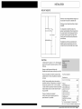
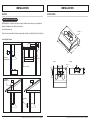
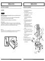
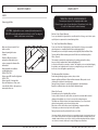
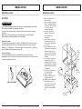
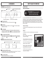
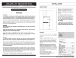
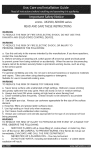
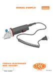
Use, Care and Installation Guide
Use, Care and Installation Guide
Read all Instructions before Installing and operating this appliance
Read all Instructions before Installing and operating this appliance
Important Safety Notice
Read and save these instructions
MODEL: AK6500, AK6536, AK6542, AK2500, AK2536
WARNING
TO REDUCE THE RISK OF FIRE OR ELECTRIC SHOCK, DO NOT USE THIS
FAN WITH ANY SOLID-STATE CONTROL DEVICE.
WARNING
TO REDUCE THE RISK OF FIRE< ELECTRIC SHOCK, OR INJURY TO
PERSONS, OBSERVCE THE FOLLOWING:
a. Use this unit only in the manner intended by the manufacturer, if you have questions,
contact the manufacturer.
b. Before servicing or cleaning unit, switch power off at service panel and lock panel
to prevent power from being switched on accidentally. When the service disconnecting
means cannot be locked, securely fasten a prominent warning device, such as a tag,
to the service panel.
CAUTION
For general ventilating use only. Do not use to exhaust cigarette ashes, hazardous
or explosive materials and vapors.
WARNING
TO REDUCE THE REISK OF RANGE TOP GREASE FIRE:
a. Never leave surface units unattended at high settings. Boilovers cause smoking
and greasy spillovers that may ignite. Heat oils slowly on low or medium settings.
b. Always turn hood ON when cooking at high heat or when flambeing food (ie:
Crepes Suzette, Cherries Jubilee, Peppercorn Beef Flambe)
c. Clean ventilating fans frequently. Grease should not be allowed to accumulate
on fan or filter.
d. Use proper pan size. Always use cookware appropriate for the size of the surface
element.
WARNING
TO REDUCE THE RISK OF FIRE, ELECTRIC SHOCK OR INJURY TO PERSONS,
OBSERVE THE FOLLOWING:
a. Installation worka nd electrical wiring must be done by qualified person (s) in
accordance with all applicable codes and standards. Including fire-rated construction.
b. Sufficient air is needed for power combustion and exhausting of gases through the
flue (chimney) of fuel burning equipment to prevent back drafting. Follow the heating
equipment manufacturer’s guideline and safety standards such as those published
by teh National Fire Protection Association (NFPA) and the American Society for
Heating, Refrigeration and Air Conditioning Engineers (ASHRAE) and the local code
authorities.
c. When cuttig or drilling into wall or ceiling, do not damage electrical wiring and other
hidden utilities.
d. Ducted fans must always vent to the outdoors.
WARNING
TO REDUCE THE RISK OF FIRE, USE ONLY METAL DUCTWORK.
CAUTION
To reduce risk of fire and to proerly exhaust air outside - Do not vent exhaust air into
soaces within walls, ceilings, attics, crawl spaces or garages.
WARNING
TO REDUCE THE RISK OF SHOCK, THIS FAN MUST BE INSTALLED WITH AN
ISOLATING WALL CONTROL/SWITCH.
OPERATION
Always leave safety grills and filters in place. WIthout these components, operating
blowers could catch onto hair, fingers and loose clothing.
The manufacturer declines all responsibility in the event of failure to observer the
instructions given here for installation, maintenance and suitable use of the product.
The manufacturer further declines all responsibility for injury due to negligence and
the warranty of the unit automatically expires due to improper maintenance.
*NOTE: Please check www.zephyronline.com for revisions before doing any custom
work.
XP02243(2)
Rev:0605
INSTALLATION
INSTALLATION
DUCTING
SPECIFICATIONS
WARNING FIRE HAZARD
NEVER exhaust air or terminate duct work into spaces between walls, crawl spaces, ceiling,attics or
garages. All exhaust must be ducted to the outside.
TOP VIEW
1"
Use metal ductwork only.
Elec K.O.
1-1/8"
Fasten all connections with sheet metal screws and tape all joints w/ certified Silver Tape or Duct Tape.
6
9"
Some Ducting Options:
7-5/8"
30"
36"
42"
22-1/4"
Side wall cap
w/ gravity damper
Side wall cap
w/ gravity damper
TOP VIEW
REAR VIEW
1"
Soffit or crawl space
Elec K.O.
Elec K.O.
10"
CL
3/4"
1-1/8"
3-1/4"
6-5/8"
7-5/8"
9"
3-1/4"
10"
7-5/8"
30"
Roof Pitch w/
Flashing & Cap
36"
42"
22-1/4"
Rear Ducting
Models: AK6500, AK6536, AK6542, AK2500, AK2536 Page 2
Models: AK6500, AK6536, AK6542, AK2500, AK2536 Page 3
INSTALLATION
INSTALLATION
MOUNTING THE RANGEHOOD
MOUNTING THE RANGEHOOD
ELECTRICAL
1. This range hood is mounted under a
kitchen cabinet unit.
2. Select preferred duct location on rear or
top of unit. (See page 6 & 7 for ducting
conversion options)
3. Begin installation by temporarily
unscrewing and removing the bottom
splash panel.
4. Reinforce cabinet base with 1x2 wood
strips if additional strengthening is
required.
5. Temporarily position the range hood in
the desired mounting location.
Measure and mark the mounting holes,
duct and electrical access locations with
a pencil.
6. Drill/cut out the required openings for
duct and electrical access; make sure the
duct opening is large enough to apply
duct tape.
7. Fasten hood onto cabinet with screws
and washers provided.
8. Install electrical.
9. Install duct work and duct-tape.
10. Reinstall the bottom splash panel.
11. Power up hood and check for leaks
around duct-tape.
WARNING
All Electrical work must by performed by qualified electrician or person with similar technical
know how and background.
For personal safety, remove house fuse or open circuit breaker before beginning installation.
Do not use extension cord or adapter plug with this appliance.
Follow National electrical codes or prevailing local codes and ordinances.
Electrical Supply:
This appliance requires a 120V 60Hz electrical supply., and connected to an individual, properly
grounded branch circuit, protected by a 15 or 20 ampere circuit breaker or time delay fuse. Wiring
must be 2 wire w/ ground. Please also refer Electrical Diagram labeled on product.
Cable Lock:
A cable locking connector (not supplied) might also be required by local codes. Check with local
requirements and codes, purchase and install appropriate connector if necessary.
6. Duct
opening
cutout
duct/silver
tape
4. Add 1x2
wood strips
Cable Lock
3. Splash
bottom panel
Models: AK6500, AK6536, AK6542, AK2500, AK2536 Page 4
Models: AK6500, AK6536, AK6542, AK2500, AK2536 Page 5
INSTALLATION
CONVERTIBLE OPTIONS
INSTALLATION
CONVERTIBLE OPTIONS
This range hood is equipped with the option of a 6” vertical discharge, 3 1/4”x10” vertical discharge, 3 1/4”x10” Rear Discharge
or 3 1/4”x10” rear discharge. Additional accessories are provided to convert to either of the above
discharge methods.
Convertible Options
Convertible Accesories
Vertical discharge
6” round
Vertical discharge
3 1/4”x10”
Horizontal rear discharge
3 1/4”x10”
Round transition adapter
Rectangular transition adapter
Rectangular rear cap (pre-mounted)
3 1/4”x10” starting collar
2. Remove top pre-mounted transition piece.
1. At rear of range hood, remove all screws on premounted rear rectangular cap and remove plate.
3 1/4”x10” Vertical Discharge
1. Remove pre-mounted 6” transition adapter or duct
opening.
2. Place rectangular transition adapter as shown
by first installing 4 screws on half round
section.
3. Remove 2 air diverter blocks through top
opening as shown.
4. Mount rectangular transition piece to top
opening as shown.
5. Mount rectangular plate (previously removed) on
top of transition adapter.
3. Mount the 3-1/4”x10” starting collar on top of
transition piece with remaining screws.
Models: AK6500, AK6536, AK6542, AK2500, AK2536
Page 6
6. Mount starting collar (provided) at rear discharge.
Models: AK6500, AK6536, AK6542, AK2500, AK2536
Page 7
CONTROLS & FEATURES
CLEANING AND MAINTENANCE
CONTROLS & FEATURES (Models AK2500, AK2536)
SELF CLEAN FEATURE
Using Self Cleaning:
2 Cycle Speed Selection
4 Cycle Lights On/Dim/Off
1 Blower On/Off
3 Delay Off
I
Delay Off Indication
II
WARNING: Use only non-corrosive & non-abrasive
grease cutting detergents.
DO NOT USE OVEN CLEANERS.
III
3 Speed Level Indication
Models AK6500, AK6536, AK6542, AK2500, AK2536 hoods are designed with a self cleaning feature.
The centrifugal blower system automatically liquefies cooking residue accumulated in its internal
housing, and deposits the residue in the cleaning cup. Nevertheless, grease from cooking can also
dry and adhere in the internal housing. Running the self clean function periodically will flush out
accumulated residue in the range hood’s internal housing.
1 Blower On/Off
By pressing
, the blower is turned On and Off.
2 Cycle Speed Selection
Cycle through 3 speed levels by pressing
, the display indicates level selected.
Cleaning Frequency:
Cleaning should be completed approximately once a month under normal use.
3 Delay Off
This switch is used for programmed shut down of blower and lights 5 minutes after the function is
once, the flashing indicator to the left indicates the function is on. The hood
activated. Press
will completely shut down in 5 minutes.
Non-corrosive, non-abrasive grease cutting spray detergents are recommended.
Self Clean:
4 Cycle Lights On/Dim/Off
Switch lights On
by selecting this switch. To Dim lights, activate
one more time, will turn lights Off
again. Selecting
1 Blower On/Off/Speed Selection
I
II
III
Turn blower on lowest speed for cleaning.
With nozzle on ‘spray’, squirt the grease cutting
detergent through the safety grill,directly onto
blower blades 10-15 times.
CONTROLS & FEATURES (Models AK6500, AK6536, AK6542)
0
Detergent:
2 Lights On/Off
Allow self cleaning to complete for 5 minutes,
turn blower off.
II
Remove cleaning cup. Clean w/ mild detergent
or in dishwasher under normal wash cycle.
I
0
(If desired, repeat above steps with water
to rinse out detergent)
1 Blower On/Off/Speed Selection
This switch turns the blower on and off and controls the speed selection. 0 is off, I is low speed,
II is medium speed and III is high speed.
2 Lights On/Off
Turn lights on I or off 0 with this switch.
Models: AK6500, AK6536, AK6542, AK2500, AK2536 Page 8
Models: AK6500, AK6536, AK6542, AK2500, AK2536 Page 9
M AINT E NANC E
WAR R ANT Y
LIGHTS
T O OB TAIN S E R VIC E UNDE R WAR R ANT Y:
You mus t pres ent proof of original purc has e date.
P leas e keep a c opy of your dated proof of purc has e (s ales s lip)
in order to obtain s ervic e under warranty.
Replacing Light Bulbs
C AUT ION: L ight bulb bec omes extremely hot when turned on.
DO NOT touc h bulb until s witc hed off and c ooled. Touc hing hot
bulbs c ould c aus e s erious burns .
One Year Service Repair Warranty:
For one year from date of original purchase, we will provide free of charge, service labor to repair
any failed parts or components due to manufacturing defects.
Ten Years Parts/Lifetime Motor Warranty:
For ten years from date of original purchase, we will provide free of charge, nonconsumable
replacement parts or components that failed due to manufacturing defects.
Consumable parts not covered by this warranty include: Light Bulbs, Metal and Carbon Filters.
The motor will have lifteime warranty replacement if it fails due to manufacturing defects.
Who is Covered:
This warranty is extended to the original purchaser for products purchased for ordinary
home use in the 48 mainland states, Hawaii and Washington D.C.
In Canada and Alaska, this warranty is Limited. There might be costs associated with shipping
the products to our designated service locations or you might need to pay service technician's
travel costs, to have the appliance repaired in-home.
Make sure all power is turned off and
bulbs are not hot.
Remove by turning bulb counter
clockwise.
If bulbs are difficult to turn due to
prolonged use, firmly attach a glass
suction cup approx. the diameter of the
bulb and turn.
Replacement bulbs are available at
specialty lighting stores.
AK6500, 6536, 6542
Purchase type: 4OR 14 mini flood light bulbs
AK2500, 2536
Purchase type: GU 10 halogen bulbs
Or to order bulbs, please call our service
center: 888-880-8368 or online parts store:
www.zephyronline.com
This Warranty will be Voided when:
Product damaged through negligence, misuse, abuse, accident.
Improper installation and failure to follow installation instructions. When product is used
commercially or other than its intended purpose.
Damaged because of improper connection with equipment of other manufacturers.
Repaired or modified by anyone other than Zephyr's Authorized Agents.
What is Not Covered:
Consumable parts such as light bulbs, filters, and fuses.
Services outside of service area and the labor cost incurred in connection with the removal,
shipping and reinstallation cost, nor does it cover any other contingent expenses.
The natural wear of finish, and wear due to improper maintenance, use of corrosive and
abrasive cleaning products, pads, and oven cleaner products.
Chips, dents or cracks due to abuse, misuse, freight damage, or improper installation.
Service trips to your home to teach you how to use the product.
Damage of product caused by accident, fire, floods or act of God.
This warranty is valid in the United States and Canada. It is non-transferable and applies only to the original purchaser and
does not extend to subsequent owners of this product. Any applicable implied warranties, including the warranty of merchantability, are limited in duration to a period of express warranty as provided herein beginning with the date of original purchase at retail and, no warranties, whether express or implied, shall apply to this product thereafter.
Models: AK6500, AK6536, AK6542, AK2500, AK2536 Page 10
Models: AK6500, AK6536, AK6542, AK2500, AK2536 Page 11
TO OBTAIN SERVICE UNDER WARRANTY
or any Service Related Questions, please call:
1-888-880-8368
Have your product proof of purchase with date ready for warranty issues.
Or write to:
Zephyr Corporation
Service and Warranty Department
395 Mendell Street
San Francisco, CA 94124
Use, Care and Installation Guide
Read all Instructions before Installing and operating this appliance
Use, Care and Installation Guide
Read all Instructions before Installing and operating this appliance
Important Safety Notice
Read and save these instructions
MODEL: AK6500, AK6536, AK6542, AK2500, AK2536
WARNING
TO REDUCE THE RISK OF FIRE OR ELECTRIC SHOCK, DO NOT USE THIS
FAN WITH ANY SOLID-STATE CONTROL DEVICE.
WARNING
TO REDUCE THE RISK OF FIRE< ELECTRIC SHOCK, OR INJURY TO
PERSONS, OBSERVCE THE FOLLOWING:
a. Use this unit only in the manner intended by the manufacturer, if you have questions,
contact the manufacturer.
b. Before servicing or cleaning unit, switch power off at service panel and lock panel
to prevent power from being switched on accidentally. When the service disconnecting
means cannot be locked, securely fasten a prominent warning device, such as a tag,
to the service panel.
CAUTION
For general ventilating use only. Do not use to exhaust cigarette ashes, hazardous
or explosive materials and vapors.
WARNING
TO REDUCE THE RISK OF RANGE TOP GREASE FIRE:
a. Never leave surface units unattended at high settings. Boilovers cause smoking
and greasy spillovers that may ignite. Heat oils slowly on low or medium settings.
b. Always turn hood ON when cooking at high heat or when flambeing food (ie:
Crepes Suzette, Cherries Jubilee, Peppercorn Beef Flambe)
c. Clean ventilating fans frequently. Grease should not be allowed to accumulate
on fan or filter.
d. Use proper pan size. Always use cookware appropriate for the size of the surface
element.
WARNING
TO REDUCE THE RISK OF FIRE, ELECTRIC SHOCK OR INJURY TO PERSONS,
OBSERVE THE FOLLOWING:
a. Installation worka nd electrical wiring must be done by qualified person (s) in
accordance with all applicable codes and standards. Including fire-rated construction.
b. Sufficient air is needed for power combustion and exhausting of gases through the
flue (chimney) of fuel burning equipment to prevent back drafting. Follow the heating
equipment manufacturer’s guideline and safety standards such as those published
by teh National Fire Protection Association (NFPA) and the American Society for
Heating, Refrigeration and Air Conditioning Engineers (ASHRAE) and the local code
authorities.
c. When cuttig or drilling into wall or ceiling, do not damage electrical wiring and other
hidden utilities.
d. Ducted fans must always vent to the outdoors.
WARNING
TO REDUCE THE RISK OF FIRE, USE ONLY METAL DUCTWORK.
CAUTION
To reduce risk of fire and to proerly exhaust air outside - Do not vent exhaust air into
soaces within walls, ceilings, attics, crawl spaces or garages.
WARNING
TO REDUCE THE RISK OF SHOCK, THIS FAN MUST BE INSTALLED WITH AN
ISOLATING WALL CONTROL/SWITCH.
OPERATION
Always leave safety grills and filters in place. WIthout these components, operating
blowers could catch onto hair, fingers and loose clothing.
The manufacturer declines all responsibility in the event of failure to observe the
instructions given here for installation, maintenance and suitable use of the product.
The manufacturer further declines all responsibility for injury due to negligence and
the warranty of the unit automatically expires due to improper maintenance.
*NOTE: Please check www.zephyronline.com for revisions before doing any custom
work.
Rev:0605
INSTALLATION
INSTALLATION
CONDUIT D’AÉRATION
SPÉCIFICATIONS
AVERTISSEMENT DE RISQUES D’INCENDIE
N‘évacuez ou ne terminez JAMAIS l’échappement du conduit dans les espaces entre les murs, les
vides sanitaires, le plafond, le grenier, ou le garage. Tous les échappements doivent être dirigés à
l’ extérieur de la maison.
Utilisez des conduits d’aération en métal seulement.
Entrée défonçable
Fixez toutes les pièces du conduit à l’aide de vis à tôle et isolez tous les joints à l’aide de ruban à
conduit ou ruban réflecteur certifiés.
Quelques options de configuration pour le conduit:
7-5/8"
30"
36"
42"
Bouche d’aération
de mur latéral
avec clapet
anti-refoulement
Bouche d’aération
de mur latéral
avec clapet
anti-refoulement
VUE DE DESSUS
VUE ARRIÈRE
1"
Retombée de plafond
ou vide sanitaire
22-1/4"
Entrée défonçable
10"
CL
3/4"
1-1/8"
3-1/4"
6-5/8"
9"
3-1/4"
10"
7-5/8"
Pente de la toiture
avec solin et chapeau
Conduit arrière
Modèles: AK6500, AK6536, AK6542, AK2500, AK2536
Page 2
Modèles: AK6500, AK6536, AK6542, AK2500, AK2536
Page 3
INSTALLATION
INSTALLATION
MONTAGE DE LA HOTTE
MONTAGE DE LA HOTTE
ÉLECTRICITÉ
1. Cette hotte s’installe sous une
armoire de cuisine.
2. Choisissez l’endroit où vous voulez
installer le conduit d’aération (sur
le dessus ou à l’arrière). Voir page
6 et 7 pour les options de
configuration du conduit.
3. Commencez l’installation en
dévissant les vis pour enlever
termporairement le pareéclaboussures.
4. Renforcez la base de l’armoire à
l’aide de frises de bois de 1x2 si
un renforcement supplémentaire
est nécessaire.
5. Placez temporairement la hotte à
l’emplacement de montage désiré.
Mesurez et marquez avec un
crayon les trous pour le montage
du conduit et des emplacements
électriques.
6. Percez et coupez les ouvertures
requises pour l’électricité et le
conduit d’aération. Assurez-vous
que l’ouverture pour le conduit doit
suffisamment large pour appliquer
le ruban adhésif.
7. Fixez la hotte à l’armoire avec les
vis et rondelles fournies.
8. Installez l’électricité.
9. Installez le conduit d’aération et
le ruban adhésif en toile.
10. Réinstallez le pare-éclaboussures.
11. Mettez la hotte en marche et
assurez-vous qu’il n’y ait pas de
fuite d’air autour des sections
scellées avec le ruban adhésif en
toile.
AVERTISSEMENT
Tous les travaux électrique doivent être effectués par un électricien qualifié ou une personne
avec l’expérience technique et le savoir-faire nécessaire.
Pour votre sécurité, enlevez le fusible ou ouvrez le disjoncteur de circuit avant de commencer
l’installation.
N’utilisez pas de cordon prolongateur ou de fiche d’adaptation avec cet électroménager.
Suivez les normes électriques nationales ou locales en viguer.
Alimentation électrique:
Cet appareil requiert une alimentation électrique de 120V 60Hz et doit être connecté à un circuit
terminal individuel et dûment mis à terre, protégé par un disjoncteur de circuit ou un fusible
temporisé de 15 ou 20 ampères. Le câblage doit compter 2 fils avec mise à terre. Veuillez vous
référez au Diagramme Électrique étiqueté sur le produit.
Connecteur d’arrimage:
Un connecteur d’arrimage (non inclus) pourrait également être exigé par les normes et
réglementations locales. Informez-vous des exigences et des normes locales. Achetez et installez
le connecteur approprié si nécessaire.
Connecteur d’arrimage
6. Duct
opening
cutout
duct/silver
tape
4. Add 1x2
wood strips
3. Splash
bottom panel
Modèles: AK6500, AK6536, AK6542, AK2500, AK2536
Page 4
Modèles: AK6500, AK6536, AK6542, AK2500, AK2536
Page 5
INSTALLATION
INSTALLATION
OPTIONS DE CONFIGURATION
OPTIONS DE CONFIGURATION
Cette hotte est pourvue en option d’un débouché vertical de 6”, d’un débouché vertical de 3¼” x 10”
ou d’un débouché arrière de 3¼” x 10”. Les accessoires supplémentaires sont disponibles pour
convertir l’appareil selon l’une des méthodes de débouché mentionnées.
Options de Configuration
Accessoires de Configuration
Débouché vertical rond de 6”
Débouché vertical de 3 1/4”x10”
Débouché arrière horizontal de 3 1/4”x10”
Adaptateur de rond à rectangle
Adaptateur de rectangle à rond (pré-monté)
Profil de calfeutrement (pré-monté)
Collier de fixation pricipal de 3¼” x 10”
Débouché arrière de 3¼” x 10”
2. Enlevez l’adaptateur pré-monté sur la partie
supérieure de l’appareil.
1. Retirez toutes les vis du couvercle rectangulaire
arrière pré-monté et enlevez le couvercle situé à
l’arrière de la hotte.
Débouché vertical de 3¼” x 10”
1. Retirez l’adaptateur de 6” pré-monté à l’ouverture du
conduit. Laisses le profil de calfeutrement fixé à son
emplacement original.
2. Placez l’adaptateur rectangulair sur le profil de
calfeutrement tel qu’indiqué sur l’image et fixez les 4
vis de la section en demi-lune.
3. Enlevez les deux déviateurs d’air de l’ouverture
de la partie supérieure de la hotte tel qu’indiqué.
5. Fixez la plaque rectangulaire préalablement enlevée
sur l’adaptateur.
3. Installez le collier de fixation principal de 3¼” x 10”
sur l’adaptateur avec les vis restantes.
Modèles: AK6500, AK6536, AK6542, AK2500, AK2536
Page 6
4. Fixez l’adaptateur rectangulaire à l’ouverture de la
partie supérieure de la hotte.
6. Installez le collier de fixation principal (fourni) à
l’ouverture du débouché arrière.
Modèles: AK6500, AK6536, AK6542, AK2500, AK2536
Page 7
COMMANDES
NETTOYAGE ET ENTRETIEN
COMMANDES (Modèles AK2500, AK2536)
AUTONETTOYAGE
4 Lumières: Allumer/Veilleuse/Éteindre
2 Choix de vitesse
Utilisation de l’autonettoyage:
1 Ventilateur Marche/Arrêt
3 Arrêt à retardement
I
Témoin d’arrêt à retardement
II
AVERTISSEMENT: N’utilisez que des nettoyants
anti-graisse non-corrosifs & non-abrasifs.
N’UTILISEZ PAS DE NETTOYANTS À FOUR.
III
Les modèles hotte AK6500, AK6536, AK6542, AK2500 et AK2536 sont conçues avec une option
d’autonettoyage. Le système de ventilation centrifuge liquéfie automatiquement la graisse accumulée
dans la structure intérieure de l’appareil et dépose les résidus dans les contentants à nettoyage.
Cependat, la graisse résultant de la cuisson pourrait également s’assécher et coller à la structure
intérieure. L’utilisation régulière de la fonction autonettoyante repoussera la graisse dans la structure
intérieure de l’appareil
Témoin des 3 vitesses du ventilateur
1 Ventilateur Marche/Arrêt
Le ventilateur est mis en marche our arrêté en pesant sur le bouton
.
2 Choix de vitesse
Choisissez entre trois vitesses différentes en pesant sur
quelle vitesse a été choisie.
. Le témoin lumineux induique
Le nettoyage devrait se faire approximativement une fois par mois dans des conditions normales
d’utilisation.
3 Arrét à retardement
Ce bouton est utilisé pour programmer l’arrêt automatique de ventilateur et des lumières 5
minutes après son activation. Appuyez sur
une fois. Le témoin lumineux clignotera pour
vous indiquer que la fonction est activée. La hotte s’arrêtera complètement après 5 minutes.
Allumez les lumières en pesant sur le bouton
. Pour mettre les lumières à basse intesité
(veilleuse) appuyez sur
une autre fois. Pesez une troisème fois sur
pour éteindre les
lumières.
1 Ventilateur Marche/Arrêt/Choix de vitesse
II
Les détergents non-corrosifs et non-abrasifs anti-graisse sont recommandés.
III
Allumez le ventilateur à la vitesse la plus lente
pour effectuer le nettoyage.
À travers la grille de sûreté, vaporisez les lames
du ventilateur de 10 à 15 fois avec du détergent.
COMMANDES (Modèles AK6500, AK6536, AK6542)
I
Détergent:
Autonettoyage:
4 Lumières: Allumer/Veilleuse/Éteindre
0
Fréquence de nettoyage:
2 Lumières: Allumer/Éteindre
II
I
0
Laissez fonctionner l’autonettoyage pendant 5
minutes puis éteignez le ventilateur.
Retirez les contenants à nettoyage. Nettoyez
avec du détergent doux ou avec le cycle de
nettoyage normal de votre lave-vaisselle.
1 Ventilateur Marche/Arrêt/Choix de vitesse
Cet interrupteur allume et éteint le ventilateur et permet d’en choisir la vitesse. À 0 il est arrête,
I à la vitesse lente, II à la vitesse moyenne et III à la vitesse maximale.
(Si désiré, répétez les étapes antérieurs avec de
l’eau pour rincez le détergent.)
2 Lumières: Allumer/Éteindre
Allumez (I) ou éteignez (0) la lumière avec cet interrupteur.
Modèles: AK6500, AK6536, AK6542, AK2500, AK2536
Page 8
Modèles: AK6500, AK6536, AK6542, AK2500, AK2536
Page 9
ENTRETIEN
GARANTIE
LUMIÈRES
POUR OBTENIR DU SERVICE SOUS GARANTIE:
Vous devez avoir une prevue originale de la date d’achat.
Veuillez garder une copie de votre preuve d’achat datée (facture)
pour obtenir des services sous garantie.
Remplacement des ampoules
ATTENTION: Les ampoules deviennent extrêmement chaudes
lorsque allumées. Veuillez NE PAS les toucher avant
de les avoir éteintes et laissées refroidir. Le contact avec les
ampoules chaudes pourrait causer de sérieuses brûlures.
Garantie de Service de Réparation d’Un An:
Garantie d’un an à partir de la d’achat. Nous offrirons un service de réparation sans frais pour toutes
les pièces ou éléments défectueux dont le malfonctionnement est dû à un défaut de fabrication.
Garantie de Deux Ans sur les Pièces:
Garantie de dix ans à partir de la date d’achat. Nous fournirons sans frais les pièces et éléments nonconsommables dont le malfonctionnement est dû à un défaut de fabrication. Les pièces
consommables qui ne sont pas couvertes par cette garantie sont les ampoules électriques, les filtres à
charbon et les filtres en métal.
Assurez-vous que l’alimentation électrique soit
coupée et que les ampoules ne soient pas
chaudes.
Qui est Couvert:
Cette garantie s’appliquent aux acheteurs originaux des produits achétes pour une utilisation
personnelle normale dans les 48 états du territoire principal américan ainshi que dans les états
d’Hawaii et de Washington D.C. Au Canada et en Alaska, cette garantie est limitée. Il pourrait y
avoir des frais pour la livraison des produits à nos points de service et vous pourriez avoir à débourser
les frais de voyage du technicien pour que l’appareil soit réparé à votre domicile.
Retirez les ampoules en les tournant dans le
sens contraire des aiguilles d’une montre.
Lorsqu’il est est difficile de retirer les
ampoules après un usage prolongé, fixez une
ventouse équivalant approximativement au
diamètre de l’ampoule et tournez.
Les ampoules de remplacement sont disponibles dans les magasins spécialisés en éclairage.
AK6536, AK 6542
Type: Ampoules électriques mini-flood 40R 14.
AK2500, AK 2536
Type: Ampoules halogènes GU 10.
Ou pour commander des ampoules, veuillez contactez notre centre de service: 888-880-8368 ou
notre magasin pour pièces en ligne: www.zephyronline.com
Cette Garantie est Annulé lorsque:
Le produit est endommagé suite à une négligence, un mauvais usage, un abus ou un accident.
L’installation a été faite incorrectement et les instructions d’installation n’ont pas été respectées. Le
produit est utilisé à des fins commerciales ou autrement que son usage souhaité par le manufacturier.
Les dommages sont le résultat d’une connexion incorrecte avec le matériel d’autres manufacturiers.
La réparation est effectuée par une personne qui ne fait pas partie des Agents Autorisés de Zephyr.
Ce qui n’est pas Couvert:
Les pièces consommables comme les ampoules électriques, les filtres et les fusibles. Les services
hors de la zone de service et les coûts de main-d’œuvre contractés lors de la déinstallation, de la
livraison et de la réinstallation. La garantie ne couvre pas non plus toute autre dépense imprévue.
L’usure naturelle du fini, l’usure due à un entretien inadéquat, l’usage de produits nettoyants corrosifs
ou abrasifs, de produits de nettoyage pour le four ou de laines d’acier. Les éclats, entailles ou craques
dus à un abus, mauvais usage,dommages de transport ou installation inadéquate. Les voyages de
service à votre domicile pour vous montrer comment utiliser l’appareil. Les dommages causés par un
accident, un incendie, une inondation ou un cas fortuit.
Cette garantie est valide au États-Unis et au Canada. Elle est incommutable et s’applique uniquement à
l’acheteur original et ne se prolonge pas aux propriétaires subséquents de ce produit. Toutes les garanties
impliquées, dont la garantie de qualité marchande, sont limitées à la période de temps de la garantie formelle
stipulée ci-dessus et commence avec la date d’achat au détail initiale. Aucune garantie, formelle ou
sous-entendue, ne s’appliquera à ce produit par la suite.
Modèles: AK6500, AK6536, AK6542, AK2500, AK2536 Page 10
Modèles: AK6500, AK6536, AK6542, AK2500, AK2536 Page 11
POUR OBTENIR DU SERVICE SOUS GARANTIE
Ou pour toute question liée au service,
veuillez contacter le:
1-888-880-8368
Ayez la prevue d’achat de votre produit avec date pour l’application de la garantie.
Ou écrivez à:
Zephyr Corporation
Service and Warranty Department
395 Mendell Street
San Francisco, CA 94124