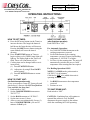
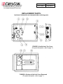
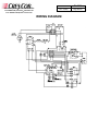
1
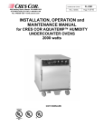
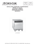
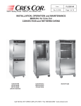
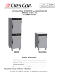
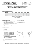
Undercounter Ovens
5925 Heisley Road • Mentor, OH 44060-1833
877/CRES COR (273-7267) • 440/350-1100
Fax: 440/350-7267 • www.crescor.com
Rev. 2 (2/05)
FL-2290
Page 1 of 9
INSTALLATION, OPERATION and
MAINTENANCE MANUAL
for CRES COR UNDERCOUNTER OVENS
1920 WATTS
CO151XUA5B
CO151X185B
Undercounter Ovens
5925 Heisley Road • Mentor, OH 44060-1833
877/CRES COR (273-7267) • 440/350-1100
Fax: 440/350-7267 • www.crescor.com
Rev. 2 (2/05)
FL-2290
Page 2 of 9
TABLE OF CONTENTS
SUBJECT
PAGE
INSTALLATION INSTRUCTIONS
3
OPERATING INSTRUCTIONS
4
Illustration, Figure 1
4
MAINTENANCE INSTRUCTIONS
How to Clean the Unit
Trouble Shooting Guide
Replacement Parts
Illustrations; Hot Unit
Wiring Diagrams
5
5,6
6,7
8
9
STACKING INSTRUCTIONS
TIMER PROGRAMMING
FL-2211
FL-2222
SERVICE POLICY and AGENCY LIST
FL-1400
Undercounter Ovens
5925 Heisley Road • Mentor, OH 44060-1833
877/CRES COR (273-7267) • 440/350-1100
Fax: 440/350-7267 • www.crescor.com
Rev. 2 (2/05)
FL-2290
Page 3 of 9
INSTALLATION INSTRUCTIONS:
VENTING YOUR OVEN:
1. The purpose of ventilation hoods is to
direct and capture smoke, grease-laden
vapors, heat, odors, or fumes.
3. Most jurisdictions consider our lowtemperature ovens (maximum
temperature is 350°F/177°C) as low-heat
appliances not requiring vent hoods.
2. Low temperature equipment (maximum
temperature 250°F/121°C) does not
produce heat, odors, fumes, grease laden
vapors or smoke and is not required to
be vented.
4. Installation must conform to local codes.
The authority having jurisdiction of
enforcement of the codes will have the
responsibility for making interpretations
of the rules.
ELECTRICAL SPECIFICATIONS:
Model Nos.
CO-151-XUA-5B-1201
CO-151-X-185B-1201
Volts
120
120
Watts
1920
1920
Amps
16.6
16.6
Hertz
60
60
Ph
1
1
NEMA
5-20P
5-20P
All models are designed for AC Service.
Model numbers may have the letters: L, M, T, or S.
HOW TO INSTALL CABINETS:
1. Remove all packing material from inside
and outside of cabinet.
2. Position cabinet on level floor; install the
cabinet interior (pan slides) if not
already installed.
3. Plug power cord into proper wall
receptacle.
NOTES: Cold food is NOT to be added when
unit is operating in HOLD mode.
For HOLD mode, preheat unit to 180°F/82°C
for 60 minutes.
To install stacking units, refer to instruction sheet FL-2211, STACKING INSTALLATION.
Undercounter Ovens
5925 Heisley Road • Mentor, OH 44060-1833
877/CRES COR (273-7267) • 440/350-1100
Fax: 440/350-7267 • www.crescor.com
Rev. 2 (2/05)
FL-2290
Page 4 of 9
OPERATING INSTRUCTIONS:
HOW TO SET TIMER:
A. Press the UP arrow-button (on the Timer) to
increase the time. The longer the button is
held down, the faster the time will increase.
Pressing the DOWN arrow-button (using the
same method) will cause the time to
decrease.
B. Press START/STOP button on Timer to
begin cooking cycle. GREEN roast light will
light up. The timing light on the Timer will
flash. Timer will count down to 0.00.
C. Cooking time can be changed while oven is
in any mode.
(1) Press START/STOP button.
(2) Adjust time by using UP and DOWN
arrow-buttons.
(3) Press START/STOP button to restart
oven.
HOW TO START UNIT:
(for first-time operation only)
A new oven needs to “burn off” factory oils and
glue before it’s first use. Do NOT load food into
oven until this has been done!
1. Push switch to “ON”.
2. Set the COOK/RETHERM thermostat to
350°F/177°C.
3. Set the Hold thermostat to 150°F/66°C.
4. Set the timer to one (1) hour.
5. Allow oven to run automatically for one (1)
hour of COOK/RETHERM cycle and 30
minutes of Hold cycle.
HOW TO START UNIT:
(after first-time operation)
Push SWITCH to “ON”.
For Automatic Operation:
1. Set COOK/RETHERM thermostat to the
cooking temperature you need.
2. Set Hold thermostat to the warming
temperature you need. Proper food holding
temperature is 140°F/60°C or higher.
3. Set Timer for the roasting time. The unit will
automatically switch to the pre-set “hold”
temperature after roasting time has expired.
For Holding Operation ONLY:
NOTES: For HOLD mode, preheat unit to
180°F/82°C for 60 minutes.
Cold food is NOT to be added when unit is
operating in HOLD mode.
1. Set HOLD thermostat to the temperature
you need.
2. Set timer at zero.
TO SHUT DOWN UNIT:
Push switch to “OFF”.
CAUTION: Ventilating fans will continue to
run until the cabinet is cool. Do NOT
disconnect the power supply to the cabinet
while the ventilating fan is still operating.
Undercounter Ovens
5925 Heisley Road • Mentor, OH 44060-1833
877/CRES COR (273-7267) • 440/350-1100
Fax: 440/350-7267 • www.crescor.com
Rev. 2 (2/05)
FL-2290
Page 5 of 9
HOW TO CLEAN THE UNIT:
BEFORE cleaning the cabinet:
1. Unplug cord from wall. Allow
cabinet to cool.
2. Do NOT hose cabinet with water.
3. Do NOT get water on controls.
4. Do NOT use abrasives or harsh
chemicals.
Wipe up spills as soon as possible.
Clean regularly to avoid heavy dirt buildup.
SOIL
Cleaning Hints:
1. Use the mildest cleaning procedure that
will do the job.
2. Always rub in the direction of polish
lines to avoid scratching the surface.
3. Use only a soft cloth, sponge, fibrous
brushes, plastic or stainless steel pads for
cleaning and scouring.
4. Rinse thoroughly with fresh water after
every cleaning operation.
5. Always wipe dry to avoid water marks.
CLEANER
Soap, ammonia or mild
detergent* and water.
METHOD
1. Sponge on with cloth
Routine Cleaning
CABINET
2. Rinse
1. Apply with damp
Stubborn Spots,
Mild abrasive made for
sponge or cloth.
Stains
Stainless Steel.
2. Rub lightly.
Inside and
Burnt on Foods or Chemical oven cleaner
Follow oven cleaner
Outside
Grease
made for Stainless Steel.
manufacturer’s directions.
1. Swab or wipe with
Hard Water Spots
Vinegar
cloth.
(Stainless Steel) & Scale
2. Rinse and dry.
*MILD DETERGENTS INCLUDE SOAPS AND NON-ABRASIVE CLEANERS.
MAINTENANCE INSTRUCTIONS
TROUBLE-SHOOTING GUIDE
IF UNIT GETS TOO HOT OR WON’T SHUT OFF, DISCONNECT
POWER AT BRANCH PANEL. DO NOT UNPLUG CORD!
If hot unit is NOT working, first check the following causes:
1. Cord is unplugged from wall outlet.
2. Circuit breaker/fuse to wall outlet is
blown.
3. Switch is turned off.
4. Thermostat is turned off, or is set too
low.
Undercounter Ovens
5925 Heisley Road • Mentor, OH 44060-1833
877/CRES COR (273-7267) • 440/350-1100
Fax: 440/350-7267 • www.crescor.com
Rev. 2 (2/05)
FL-2290
Page 6 of 9
MAINTENANCE INSTRUCTIONS
TROUBLE-SHOOTING GUIDE, continued
PROBLEM
Cabinet does not heat, or
doesn’t heat properly
Blowers do not operate
Heater will not shut off
Vent fan does not shut off
POSSIBLE CAUSE
1. Thermostat
2. Heater relay
3. Loose wiring at heater relay
4. Hi-limit switch
5. On/Off switch
1. On/Off Switch
2. Blower
1. Thermostat
2. Relay
1. Vent fan switch
2. Control compartment still hot
Vent fan does not operate 1. Vent fan switch
(See Note)
2. Vent fan
SOLUTION
1. Replace
2. Replace
3. Replace
4. Replace
5. Replace
1. Replace
2. Replace
1. Replace
2. Replace
1. Replace
2. Wait until it cools
Check “Heaters will not shutoff”
1. Replace
2. Replace
NOTE: Vent fans will not operate until the control compartment requires ventilation to limit
temperatures. Replacement of electrical components must be done by a qualified electrician.
Refer to our Service Agency list, FL-1400 (found in the back of this manual), of authorized service
centers. Instructions for replacing parts are included in replacement parts list.
REPLACEMENT PARTS:
Include all information on nameplate when ordering parts.
Cabinet Replacement Parts
DESCRIPTION
Hot Unit, 120V, 1 Ph
Door Latch Kit
Latch Strike
Door Hinge
Door Assembly
Door Gasket
Interior
Casters
Casters w/brake
MODEL PREFIX CO-151
-XUA5B
-X185B
HU675045
HU675046
1006-120-01
1006-120-01
1006-120-02
1006-120-02
0519-074
0519-074
1221-545
1221-546
0861-250
0861-251
0621-281
1104-107
0569-310
0569-310
0569-310B
0569-310B
Undercounter Ovens
5925 Heisley Road • Mentor, OH 44060-1833
877/CRES COR (273-7267) • 440/350-1100
Fax: 440/350-7267 • www.crescor.com
Rev. 2 (2/05)
FL-2290
Page 7 of 9
REPLACEMENT PARTS:
Include all information on nameplate when ordering parts.
Figure 2
Control Panel
Hot Unit Replacement Parts
ITEM DESCRIPTION
1. Switch (On/Off)
2. Timer, Digital
3. Knob, Thermostat
3. Control Board
4. Pilot Light, Yellow
5. Pilot Light, Green
6. Thermometer
7. Vent Fan
8. Fan Guard
9. Blower Kit
10. Relay
CMP Part No.
0808-113
0849-088
0595-061
0848-057-K3
0766-094
0766-098
5238-031
0769-165
0769-167
0769-005-K
0857-130
ITEM DESCRIPTION
11. Terminal Block, Front
12. Terminal Block
13. Switch, Fan
14. Relay – Timer
15. Hi-Limit (Switch)
16. Sensor
17. Sensor Bushing
18. Transformer
19. Power Cord
20. Heater Kit
21. Strain Relief
CMP Part No.
0852-096
0852-093
0848-034
0857-100
0848-079
0848-058-K1
0818-014
0769-159
0810-039-06
0811-022
0818-057
Undercounter Ovens
5925 Heisley Road • Mentor, OH 44060-1833
877/CRES COR (273-7267) • 440/350-1100
Fax: 440/350-7267 • www.crescor.com
Rev. 2 (2/05)
FL-2290
Page 8 of 9
REPLACEMENT PARTS:
Include all information on nameplate when ordering parts.
FIGURE 3; Hot Unit w/o Top Cover
(For parts description, refer to page 7.)
FIGURE 4; Bottom of Hot Unit Cover Removed
(For parts description, refer to page 7.)
Undercounter Ovens
5925 Heisley Road • Mentor, OH 44060-1833
877/CRES COR (273-7267) • 440/350-1100
Fax: 440/350-7267 • www.crescor.com
Rev. 2 (2/05)
WIRING DIAGRAM
FL-2290
Page 9 of 9