1
Service
This manual is to be used by qualified appliance
technicians only. Maytag does not assume any
responsibility for property damage or personal
injury for improper service procedures done by
an unqualified person.
This Base Manual covers general information
Refer to individual Technical Sheet
for information on specific models
This manual includes, but is
not limited to the following:
Freestanding
Gas Range
AGR4400ADW
AGR4412ADB/Q/S/W
AGR5712ADB/Q/S/W
CPL1100ADH/L/Q/T/W
CPL1110ADH/L/T
CPR1100ADQ/W
CGL1100ADQ/W
CGR1110ADQ/W
CGR1125ADQ/W
CGR1415ADH
CGR1425ADH/Q/S/T/W
CGR3725ADB/Q/S/W
CG31200ADQ/V/W
CG31400ADW
CG31600ADB/Q/V
CG34800ADQ/S/T/V/W
CP31200ADV
CP31600ADQ/V
LGR3330ADB/W
LPR1115ADW
MGR5751ADB/Q/W/S
MGR5752ADW
MGR4451ADB/Q/W/S
MGR4452ADB/Q/W
PGR4420LDQ/W
PGR5720LDQ/W
16023522
December 2004
©2004 Maytag Services
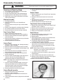
Important Information
Pride and workmanship go into every product to provide our customers with quality products. It is possible, however,
that during its lifetime a product may require service. Products should be serviced only by a qualified service
technician who is familiar with the safety procedures required in the repair and who is equipped with the proper tools,
parts, testing instruments and the appropriate service information. IT IS THE TECHNICIANS RESPONSIBILITY TO
REVIEW ALL APPROPRIATE SERVICE INFORMATION BEFORE BEGINNING REPAIRS.
Important Notices for Servicers and Consumers
!
WARNING
To avoid risk of severe personal injury or death, disconnect power before working/servicing on appliance to avoid
electrical shock.
To locate an authorized servicer, please consult your telephone book or the dealer from whom you purchased this
product. For further assistance, please contact:
Customer Service Support Center
CAIR Center
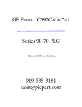
Web Site
Telephone Number
WWW.AMANA.COM ................................................ 1-800-843-0304
WWW.MAYTAG.COM ............................................. 1-800-688-9900
CAIR Center in Canada ........................................... 1-800-688-2002
Amana Canada Product ........................................... 1-866-587-2002
Recognize Safety Symbols, Words, and Labels
! DANGER
DANGER—Immediate hazards which WILL result in severe personal injury or death.
!
WARNING
WARNING—Hazards or unsafe practices which COULD result in severe personal injury or death.
!
CAUTION
CAUTION—Hazards or unsafe practices which COULD result in minor personal injury, product or property
damage.
2
16023522
©2004 Maytag Services
Table of Contents
Important Information .................................................... 2
Important Safety Information
Safety Practices for Servicer .................................... 4
Servicing .................................................................. 4
Receiving Oven ........................................................ 5
Using the Oven ........................................................ 5
Baking, Broiling, and Roasting ................................. 6
Connecting Range to Gas ........................................ 6
Electrical Requirements ........................................... 6
Extenstion Cord ....................................................... 6
Product Safety Devices ............................................ 6
General Information
Cooking Nomenclature ............................................. 7
Specifications .......................................................... 8
Placement of the Oven ............................................. 8
Do Not Block Air Vents ............................................ 8
Location of Model Number ........................................ 8
Model Identification .................................................. 8
Service ..................................................................... 8
Parts and Accessories ............................................. 8
Extended Service Plan ............................................. 8
Grounding ................................................................ 9
Range Description ................................................... 10
Troubleshooting Procedures ........................................ 11
Testing Procedures
Component Testing Procedures .............................. 14
M1 Oven Control Testing ......................................... 16
Quick Test Mode ..................................................... 17
Description of Error Codes ...................................... 17
Disassembly Procedures
Removing and Replacing Range .............................. 20
Maintop Assembly .................................................. 20
Front Control Panel ................................................. 20
Control Panel .......................................................... 20
Control Board Assembly ......................................... 20
Rocker Switch ......................................................... 20
Top Surface Valve and Spark Switch ....................... 20
Sealed Burner ......................................................... 20
Open Burner ........................................................... 21
Oven Sensor ........................................................... 21
Bake Burner and Ignitor ........................................... 21
Broil Burner and Ignitor ............................................ 21
Valve/Regulator Assembly ...................................... 21
Manual Oven Door Latch Assembly ........................ 21
Spark Module .......................................................... 21
©2004 Maytag Services
Oven Door Removal ................................................. 21
Oven Door Hinge Reciever ....................................... 22
Side Panel Removal ................................................ 22
Backguard .............................................................. 22
Storage Drawer Removal ......................................... 22
Storage Drawer Track Removal ............................... 22
Warming Drawer Removal ....................................... 22
Warming Drawer Element ....................................... 22
Convenience Outlet/Circuit Breaker
(Canadian Models Only) .......................................... 22
Oven Light Assembly .............................................. 23
Power Cord ............................................................. 23
Frameless Door Disassembly
(Large and Standard Windows) ............................... 23
Frameless Oven Door .............................................. 24
Door Disassembly (No Window) ............................. 25
Appendix A: Installation Instructions
Models CP31200AD*, CG31200AD* ..................... A-2
Models CPL1100AD*, CGL1100AD* ..................... A-4
Model LPR1115AD* .............................................. A-6
Models CPL1100AD*, CGL1100AD*,
CP31200AD*, CG31200AD*, LPR1115AD* ........ A-8
All models except CP31200AD*, CG31200AD*,
CPL1100AD*, CGL1100AD*, LPR1115AD* ........ A-9
Appendix B: Use and Care
Models CP31200AD*, CG31200AD*,
CPL1100AD*, CGL1100AD* ............................... B-2
Models CPR1100AD*, CGR1110AD*,
CGL1100AD*, CGR1415AD*, CGR1425AD*,
CGR3725AD*, CP31200AD*, CG31200AD*,
CG31400AD*, CP31600AD*, CG31600AD*,
CG34800AD* ..................................................... B-4
Models AGR4400AD*, AGR4412AD*,
AGR5712AD*, MGR4451AD*, MGR4452AD*,
MGR575*AD*, PGR4420LD*, PGR5720LD* ....... B-7
Care and Cleaning ............................................... B-10
Appendix C: LP/Natural Gas Conversion
Models CP31200AD*, CG31200AD* ..................... C-2
Models CPL1100AD*, CGL1100AD* ..................... C-4
Model CPR1100AD* .............................................. C-5
Model LPR1115AD* .............................................. C-8
Models AGR5712AD*, CG34800AD*,
CGR3725AD*, MGR5751AD*, MGR5752AD*,
PGR5720AD* ..................................................... C-9
Models AGR4400AD*, AGR4412AD*,
MGR4451AD*, MGR4452AD*, PGR4420LD*,
CGR1425AD*, CGR1415AD*, CGR1110AD*,
CP31600AD*, CG31400AD* ............................. C-12
16023522
3
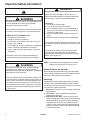
Important Safety Information
Recognize this symbol as a safety precaution.
!
!
!
Due to the nature of cooking, fires can occur as a
result of overcooking or excessive grease. Although a
fire is unlikely, if one occurs proceed as follows:
WARNING
If the information in this manual is not followed exactly,
a fire or explosion may result causing property
damage, personal injury or death.
Do not store or use gasoline or other flammable vapors
or liquids in the vicinity of this or any other appliance.
WHAT TO DO IF YOU SMELL GAS
• Extinguish any open flame.
• Do not try to light any appliance.
• Do not touch any electrical switch; do not use any
phone in your building.
• Immediately call your gas supplier from a neighbor’s
phone. Follow the gas supplier’s instructions.
• If you cannot reach your gas supplier, call the fire
department.
Installation and service must be performed by an
authorized installer, service agency or gas supplier.
!
W A R NIN G
Oven Fires
1. Do not open the oven door.
2. Turn all controls to the OFF position.
3. As an added precaution turn off the electricity at
the main circuit breaker or fuse box and the gas
at the main supply valve.
4. Allow the food or grease to burn itself out in the
oven.
If smoke or fire persist call the local fire department.
To avoid risk of property damage or personal injury do
not obstruct the flow of combustion or ventilation air to
the oven.
To avoid risk of electrical shock, serious personal
injury or death: Verify the oven has been properly
grounded and always disconnect the electrical supply
before servicing this unit.
NOTE: The maximum gas supply pressure for these
models must not exceed 14 inches W.C.P.
W A RNIN G
To avoid risk of electrical shock, property damage,
personal injury or death; verify wiring is correct, if
components were replaced. Verify proper and complete
operation of unit after servicing.
This gas appliance contains or produces a chemical or
chemicals which are known to the state of California to
cause cancer, birth defects or other reproductive harm.
To reduce the risk from substances in the fuel or from
fuel combustion make sure this appliance is installed,
operated, and maintained according to the instructions
in this manual.
Safety Practices for Servicer
Safe and satisfactory operation of gas ranges depends
upon its design and proper installation. However, there is
one more area of safety to be considered:
Servicing
Listed below are some general precautions and safety
practices which should be followed in order to protect
the service technician and consumer during service and
after service has been completed.
1. Gas smell—Extinguish any and all open flames and
open windows.
2. Turn gas off—Service range with gas turned off
unless testing requires it.
3. Checking for gas leaks—Never check for leaks
with any kind of open flame. Soap and water solution
should be used for this purpose. Apply solution to
suspected area and watch for air bubbles which
indicates a leak. Correct leaks by tightening fittings,
screws, connections, applying approved compound,
or installing new parts.
4
16023522
©2004 Maytag Services
Important Safety Information
4. Using lights—Use a hand flashlight when servicing
ranges or checking for gas leaks. Electric switches
should not be operated where leaks are suspected.
This will avoid creating arcing or sparks which could
ignite the gas. If electric lights are already turned on,
they should not be turned off.
5. Do not smoke—Never smoke while servicing gas
ranges, especially when working on piping that
contains or has contained gas.
6. Check range when service is completed—After
servicing, make visual checks on electrical
connection, and check for gas leaks. Inform
consumer of the condition of range before leaving.
7. Adhere to all local regulations and codes when
performing service.
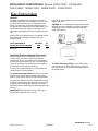
Receiving Oven
• Installer needs to show consumer location of the range
gas shut-off valve and how to shut it off.
• Authorized servicer must install the range, in
accordance with the Installation Instructions.
Adjustments and service should be performed only by
authorized servicer.
• Plug range into a 120–volt grounded outlet only. Do
not remove round grounding prong from the plug. If in
doubt about grounding of the home electrical system,
it is consumers responsibility and obligation to have an
ungrounded outlet replaced with a properly grounded
three-prong outlet in accordance with the National
Electrical Code. Do not use an extension cord with
this appliance.
• Insure all packing materials are removed from the
range before operating it, to prevent fire or smoke
damage should the packing material ignite.
• Ensure range is correctly adjusted by a qualified
service technician or installer for the type of gas
(Natural or LP). Some ranges can be converted for
use with Natural or LP gas.
• With prolonged use of a range, high floor
temperatures could result. Many floor coverings will not
be able to withstand this kind of use. Never install
range over vinyl tile or linoleum that cannot withstand
high temperatures. Never install range directly over
carpeting.
Using the Oven
• Do not leave children alone or unattended where a
range is hot or in operation. They could be seriously
burned.
• Do not allow anyone to climb, stand or hang on the
door. They could damage the range and cause severe
personal injury.
• Wear proper apparel. Loose fitting or hanging garments
should never be worn when using oven. Flammable
material could ignite if brought in contact with flame or
hot oven surfaces which may cause severe burns.
©2004 Maytag Services
• Never use range for warming or heating a room. This
may cause burns, injuries, or a fire.
• Do not use water on grease fires.
• Do not let grease or other flammable materials collect
in or around range.
• Do not repair or replace any part of range unless it is
recommended in this manual.
• Use only dry potholders. Moist or damp potholders
used on hot surfaces may result in a burn from steam.
Do not let a potholder touch the flame. Do not use a
towel or a bulky cloth as a potholder.
• Never leave range unattended while cooking.
Boilovers can cause smoking and may ignite.
• Only certain types of glass/ceramic, earthenware, or
other glazed utensils are suitable for oven use.
Unsuitable utensils may break due to sudden
temperature change.
• Use care when opening oven door. Let hot air or
steam escape before removing or replacing food.
• Do not heat unopened food containers in oven.
Buildup of pressure may cause a container to burst and
result in injury.
• Keep range vent ducts unobstructed.
• Place oven racks in desired location while oven is cool.
If a rack must be moved while oven is hot, use a dry
potholder.
• Do not use aluminum foil to line oven bottom or racks.
Aluminum foil can cause a fire and will seriously affect
baking results, and damage to porcelain surfaces.
• Do not touch interior surfaces of oven during or
immediately after use. Do not let clothing or other
flammable materials come in contact with bake or broil
burners.
• Other areas of the oven can become hot enough to
cause burns, such as vent openings, window, oven
door and oven racks.
• To avoid steam burns, do not use a wet sponge or cloth
to wipe up spills on hot cooking area.
• Do not store combustible or flammable materials, such
as gasoline or other flammable vapors and liquids near
or in oven.
• Do not clean oven door gasket located on back of the
door. Gasket is necessary to seal the oven and can be
damaged as a result of rubbing or being moved.
• Do not drape towels or any materials on oven door
handles. These items may ignite causing a fire.
!
CAUTION
Do not store items of interest to children in cabinets
above range. Children may climb on oven to reach
these items and become seriously injured.
16023522
5
Important Safety Information
Baking, Broiling, and Roasting
• Do not use oven area for storage.
• Stand back from range when opening door of a hot
oven. Hot air or steam can cause burns to hands,
face, and eyes.
• Do not use aluminum foil anywhere in the oven. This
could result in a fire hazard and damage the range.
• Use only glass cookware appropriate for use in gas
ovens.
• Always remove broiler pan from oven when finished
broiling. Grease left in pan can catch fire if oven is
used without removing grease from the broiler pan.
• Meat that is close to the flame may ignite when
broiling. Trim any excess fat to help prevent excessive
flare-ups.
• Make sure broiler pan is placed correctly to reduce any
possibility of grease fires.
• Should a grease fire occur in the broiler pan, turn off
oven, and keep oven door closed until fire burns out.
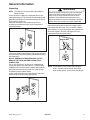
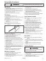
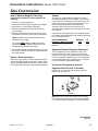
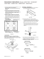
Gas Burner Orifices
Universal orifices are
used on most valves.
They must be adjusted
or set for the type of gas
being used Natural or
LP.
After servicing a valve or
orifice verify it is
adjusted properly before
completing service.
Oven Safety Valve
Oven valve is designed
to be a safety valve. Two
basic designs are used
in gas ranges.
Hydraulic type valve
Electric type valve
Both types are safety
valves because they are
indirectly operated or
controlled by the oven
thermostat, which
controls a pilot flame or
electric ignitor, to open
and close the oven valve.
Connecting Range to Gas
Install manual shut-off valve in gas line for easy
accessibility outside range. Be aware of the location of
the shut-off valve.
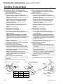
Electrical Requirements
120-volt, 60 Hertz, 15 amp, individual circuit which is
properly grounded, polarized and protected by a circuit
breaker or fuse.
Grounded Oven Frame
Extension Cord
Due to possible pinching during installation, extension
cords should not be used on products.
Extension cords will adversely affect the performance of
spark system.
Product Safety Devices
Safety devices and features have been engineered into
the product to protect consumer and servicer. Safety
devices must never be removed, bypassed, or altered in
such a manner as to defeat the purpose for which they
were intended.
Listed below are various safety devices together with the
reason each device is incorporated in the gas ranges.
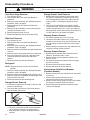
Pressure Regulator
6
Maintains proper and
steady gas pressure for
operation of oven
controls. Regulator must
be set for the type of
gas being used Natural
or LP. After servicing
regulator, make certain it
is set properly before
completing service.
16023522
Ground prong on power
cord is connected to the
frame, usually a green
lead fastened by a
screw. In addition, any
part or component
capable of conducting
an electric current is
grounded by its
mounting.
If any ground wire,
screw, strap, nut, etc. is
removed for service, or
any reason, it must be
reconnected to its
original position with
original fastener before
the appliance is put into
operation again.
Failure to do so can
create a possible shock
hazard.
©2004 Maytag Services
General Information
This manual provides basic instructions and suggestions
for handling, installing and servicing gas ranges.
The directions, information, and warnings in this manual
are developed from experience with, and careful testing
of the product. If the unit is installed according to this
manual, it will operate properly and will require minimal
servicing. A unit in proper operating order ensures the
consumer all the benefits provided by clean, modern gas
cooking.
This manual contains information needed by authorized
service technicians to install and service gas ranges.
There may be, however, some parts which need further
explanation. Refer to the Installation Instructions, Use
and Care, Technical Sheets or the toll-free technical
support line.
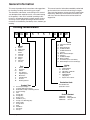
Cooking Nomenclature
M
G
R
5
7
5
1
A
D
W
Color
A
B
C
H
L
P
Q
S
T
W
F
N
Brand
A
C
G
Amana
Magic Chef
Graffer &
Sattler
Hardwick
Jenn-Air
Maytag
Norge
Universal
Crosley
H
J
M
N
U
Y
Listing
Fuel
B
D
E/J
G
L
M
P
X
W
Almond on Almond
Black
Brushed Chrome
Traditional White
Traditional Almond
Prostyle
Monochromatic Bisque
Stainless
Traditional Bisque
White on White
Frost White (True Color White)
Natural Bisque (True Color Bisque)
A
C
D
G
M
P
Butane
Dual Fuel
Electric
Gas, Natural
Liquid Propane
Microwave
Standing Pilot
No Fuel
Warming Drawer
X
UL/AGA
CSA/CGA/CUL
Dual Listed
220-240 V / 50-60 Hz
Military Model
PSB Approved
(Singapore)
Export 120 V / 60 Hz
Production Code
This identifies the
production version.
Product Type
A
C
D
E
G
L
M
P
Q
R
S
T
V
W
Y
Z
Accessory/Cartridge
Cooktop Updraft/Countertop
Downdraft Cooktop or Warming Drawer
Eyelevel Range
Grill
Range (20")
Range (36")
Drop In (24")
Wall Oven (27")
Range, Free-Standing (30")
Slide-In (30")
Range Hood
OTR
Wall Oven
RV Range
RV Top
©2004 Maytag Services
Feature Content
1000-3999
4000-6999
7000-9999
16023522
Brands
Maytag/Amana
Jenn Air
7
General Information
Specifications
Model Identification
Refer to individual Technical Sheet for specification
information.
Complete enclosed registration card and promptly return.
If registration card is missing:
• For Amana product call 1-800-843-0304 or visit the
Web Site at www.amana.com
• For Maytag product call 1-800-688-9900 or visit the
Web Site at www.maytag.com
• For product in Canada call 1-866-587-2002 or visit the
Web Site at www.maytag.com
When contacting provide product information located on
rating plate. Record the following:
Model Number:
___________________
Manufacturing Number:
___________________
Serial or S/N Number:
___________________
Date of purchase:
___________________
Dealer’s name and address:
___________________
Placement of the Oven
This freestanding range must be placed in the kitchen or
comparable room. All safety guidelines must be followed
and free air flow around the range is essential (see
Chapter 2).
Do Not Block Air Vents
All air vents must be kept clear during cooking. If air
vents are covered during operation, the oven may
overheat. If this occurs, a sensitive, thermal safety device
automatically removes power to the oven, rendering the
oven inoperable. The oven will remain in this state until it
has sufficiently cooled.
Location of Model Number
To request service information or replacement parts, the
service center will require the complete model, serial, and
manufacturing number of your freestanding range. The
number can be found on a metal tag located on the back
of the control panel. Reach behind the top left corner of
the control panel and rotate the tags up to view the data.
Rating Label
Model Number
Service
Keep a copy of sales receipt for future reference or in
case warranty service is required. To locate an authorized
servicer:
• For Amana product call 1-800-628-5782 or visit the
Web Site at www.amana.com
• For Maytag product call 1-800-462-9824 or visit the
Web Site at www.maytag.com
• For product in Canada call 1-866-587-2002 or visit the
Web Site at www.maytag.com
Warranty service must be performed by an authorized
servicer. We also recommend contacting an authorized
servicer, if service is required after warranty expires.
Parts and Accessories
Purchase replacement parts and accessories over the
phone. To order accessories for your product call:
• For Amana product call 1-877-232-6771 or visit the
Web Site at www.amana.com
• For Maytag product call 1-800-688-9900 or visit the
Web Site at www.maytag.com
• For product in Canada call 1-866-587-2002 or visit the
Web Sites at www.maytag.com
Extended Service Plan
We offer long-term service protection for this new oven.
• Dependability PlusSM Extended Service Plan is
specially designed to supplement Maytag’s warranty.
This plan covers parts, labor, and travel charges.
Call 1-800-925-2020 for information.
8
16023522
©2004 Maytag Services
General Information
Grounding
!
NOTE: This appliance must be properly grounded, for
personal safety.
Power cord on this appliance is equipped with a threeprong grounding plug. This matches standard three-prong
grounding wall receptacle to prevent possibility of electric
shock from this appliance.
Consumer should have wall receptacle and circuit
checked by qualified electrician to verify receptacle is
properly grounded.
W ARNIN G
Attaching adapter ground terminal to wall receptacle
cover screw does not ground appliance unless the
cover screw is metal and not insulated, and wall
receptacle is grounded through the house wiring.
Consumer should have circuit checked by a qualified
electrician to verify receptacle is properly grounded.
When disconnecting power cord from adapter, always
hold adapter with one hand. If this is not done, adapter
ground terminal is very likely to break with repeated use.
Should this happen, DO NOT USE appliance until a
proper ground has been established.
Neutral Wire
Ground
It is the consumers responsibility to replace standard twoprong wall receptacles with properly grounded three-prong
wall receptacles.
DO NOT, UNDER ANY CIRCUMSTANCES, CUT OR
REMOVE THE THIRD (GROUND) PRONG FROM
POWER CORD.
For 15 amp circuits only, do not use an adapter on 20
amp circuit. Where local codes permit, a TEMPORARY
CONNECTION may be made to a properly grounded twoprong wall receptacle by the use of a UL listed adapter
(available at most hardware stores).
Larger slot on adapter must be aligned with larger slot in
the wall receptacle to provide proper polarity.
©2004 Maytag Services
Hot Line
NOTE: Circuit tester can be used to verify voltage at
outlet. Connect one lead to hot line and the
other lead to ground. Circuit tester should light.
16023522
9
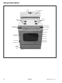
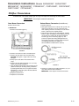
Range Description
Control
Oven Light Switch
Surface
Burners
Surface
Burners
Surface Burner
Control Knobs
Surface Burner
Control Knobs
Door Handle
Broil Burner
Oven Door
Oven Light
and Sensor
Oven Racks
Door Hinge
Door Hinge
Bake Burner
Model Number
Rating Label
Service/
Warming
Drawer
10
16023522
©2004 Maytag Services
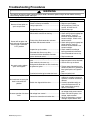
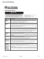
Troubleshooting Procedures
!
WARNING
To avoid risk of electrical shock, personal injury or death; disconnect power and gas to oven before servicing,
unless testing requires power and/or gas.
Problem
Burners will not ignite; no
spark at top burner.
Burner will not ignite. No
spark to burner ignitors when
burner knob is rotated to
“LITE” position.
No spark or only random
spark at one ignitor.
Unit continues to spark after
knob is turned to OFF
position.
No oven operation in bake or
broil.
©2004 Maytag Services
Possible Cause
Correction
Poor ground on burner cap ........................... • Clean burner cap.
Weak or failed spark module ........................ • Replace spark module.
Low gas pressure .......................................... • Verify pressure 4” WCP for
natural, 10” WCP for LP.
Clogged burner port ...................................... • Clean burner cap.
No 120 VAC to range .................................... • Verify voltage at wall outlet.
Micro switch contacts not closing .................. • Check wiring against appropriate
wiring diagram. Verify all
terminals and connections are
correct and tight. Check micro
Faulty wiring. Bad connection at burner
switch contacts.
electrode and electrode socket ..................... • Check wiring against appropriate
wiring diagram. Verify all
terminals and connections are
correct and tight.
Inoperative spark module .............................. • Check module according to
testing procedures information.
Electrode dirty. Burner cap dirty .................... • Clean electrode or burner cap.
Cracked or broken electrode, electrode
wire or electrode socket ................................ • Replace electrode.
Check for cracked ignitor or pinched ignitor
wire ............................................................... • Replace ignitor lead or electrode.
Poor continuity to burner cap......................... • Clean burner cap and lead.
Bad ground connection or lack of continuity
to ground or ignitor ........................................ • Tighten ground connection and
correct any breaks in ground path
from ignitor path to unit ground
path.
Cracked or broken ignitor extension lead...... • Replace ignitor lead.
Shorted valve switch/harness........................ • Replace switch/harness. If
shorting is caused by excessive
spillovers, customer education is
advised.
Switch has slipped off the valve .................... • Carefully reposition switch on
valve and rotate from OFF to
high, several times to verify
switch is not broken.
No voltage to control...................................... • Check for 120 VAC at control. If
no voltage check power source.
No voltage from control ................................. • Check 120 VAC to ignitor, if no
voltage, replace control.
Loose wire connection or broken wire........... • Verify all connections are clean
and tight, replace broken wire.
16023522
11
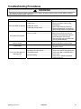
Troubleshooting Procedures
!
WARNING
To avoid risk of electrical shock, personal injury or death; disconnect power and gas to oven before servicing,
unless testing requires power and/or gas.
Problem
No gas flows to burner.
Ignitor glows red.
Gas flows to bake/broil
burner, but burner does not
light.
Broil burner shuts off shortly
after the start of self-clean
operation. Bake and broil
functions operate normally.
Fan motor does not operate.
12
Possible Cause
Correction
Failed ignitor. ................................................. • Check ignitor current draw, 3.2 –
3.6 Amps. Replace ignitor, if it
fails test.
Gas pressure too high ................................... • Check for correct gas pressure.
Natural gas pressure should be 4"
WCP and LP gas pressure should
be 10" WCP.
Failed gas valve............................................. • Check gas valve for continuity.
Loose wire connection or broken wire ........... • Verify all connections are clean
and tight, replace broken wire.
Ignitor positioned too far from burner ............ • Reposition ignitor closer to
bake/broil burner.
Dirt or grease in orifice or burner................... • Clean orifice or burner.
Insufficient gas pressure ............................... • Check for correct gas pressure.
Natural gas pressure should be 5"
WCP and LP gas pressure should
be 10" WCP.
Power outage ................................................ • Verify power is present at unit.
Verify that the circuit breaker is
not tripped.
• Replace household fuse, but do
not fuse capacity.
Power outage ................................................ • Verify power is present at unit.
Verify that the circuit breaker is
not tripped.
• Replace household fuse, but do
not fuse capacity.
Control Error .................................................. • See “Control Systems
Troubleshooting.”
No power to fan motor ................................... • Check for 120 VAC supplied at
fan motor. If no voltage is
present, check for broken or
loose wiring between fan motor
and relay board. If voltage is
present at fan motor, go to the
next step.
Failed fan motor or winding/frozen shaft ....... • Check motor winding for
continuity. Check for a frozen
motor shaft. Check for broken
wiring between motor and neutral
terminal block.
16023522
©2004 Maytag Services
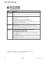
Troubleshooting Procedures
!
WARNING
To avoid risk of electrical shock, personal injury or death; disconnect power and gas to oven before servicing,
unless testing requires power and/or gas.
Problem
Oven light does not operate.
Oven door will not unlock
Oven smokes/odor first few
times of usage
Failure Codes
Part or all of the appliance
does not work
©2004 Maytag Services
Possible Cause
Correction
Failed oven lamp ..................................... • Check lamp and replace is necessary.
Failed wiring ............................................ • Check for broken, loose or dirty
connections.
Failed light socket.................................... • Check light socket for continuity.
Failed light plunger/switch ....................... • Check plunger/switch for continuity.
Check wiring diagram for application.
Oven is cleaning ...................................... • Allow cycle to complete.
Oven is still hot ........................................ • Door will not unlock until unit has
cooled to safe temperature. Do not
force door open, this will void
warranty. Blow cool air on door latch
area to quicken process.
Normal..................................................... • Minor smoking and/or odor is normal
the first few times of oven usage.
Electronically Controlled .......................... • See Testing Procedures for
diagnostic checks.
Power Outage.......................................... • Check power supply/circuit breaker.
Improperly set oven controls ................... • Verify oven controls are properly set.
Oven door locked .................................... • Verify oven door is unlocked after a
clean cycle.
Delayed cooking ...................................... • Verify oven is not set for delayed
cooking program.
16023522
13
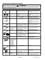
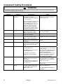
Component Testing Procedures
!
WARNING
To avoid risk of electrical shock, personal injury or death; disconnect power and gas to oven before servicing,
unless testing requires power and/or gas.
Illustration
Component
Oven light socket
Rocker switch
Door lock switch
NC
NO
COM
Manual Latch
assembly with switch
Bake burner
Bake burner
Models CPL1100AD*,
CGL1100AD*
Broil burner
Ignitor
Temperature sensor
Test Procedure
Results
Test continuity of receptacle terminals ... Indicates continuity with bulb inserted.
Measure voltage at oven light................. 120 VAC, see wiring diagram for terminal
identification.
If no voltage present, check wiring.
Measure continuity of switch positions:
Closed................................................. Continuity
Open ................................................... Infinite
Switch connection in following
positions: Not engaged ........................
Engaged ..............................
Disconnect wires and test for
continuity per wiring diagram..................
Normally Open
COM-NO=Open, COM-NC=Closed
COM-NO=Closed, COM-NC=Open
See wiring diagram for schematic layout.
Refer to Parts Manual for replacement
components.
NOTE: Control will cancel function if
latch is moved to LOCK position during
Bake or Broil.
Verify gas is supplied.
Air shutter opening: .469" to .531".
Verify proper orifice installed-Nat or LP .. Blue flame with no yellow tipping.
Check for obstructions, contamination
in ports or damage ................................. Replace if punctured or torn.
Verify gas is supplied.
Air shutter opening: .349" to .411".
Verify proper orifice installed-Nat or LP .. Blue flame with no yellow tipping.
Check for obstructions, contamination
in ports or damage ................................. Replace if punctured or torn.
Verify gas is supplied.
Air shutter opening: .281" to .343".
Verify proper orifice installed-Nat or LP .. Blue flame with no yellow tipping.
Check for obstructions, contamination
in ports or damage ................................. Replace if punctured or torn.
Test for voltage at terminals ................... 120 VAC
Test for amount of amperage in circuit ... 3.2 to 3.6 Amps.
(Ignitor may glow, but not have
sufficient amperage to open valve).
Measure resistance ................................ Approximately 1000 Ω at room
temperature 80°F.
Gas thermostat
Models AGR4400AD*,
CGR1415AD*,
CGR1110AD*,
CGL1100AD*,
CPL1100AD*,
CP31200AD*,
CG31200AD*,
CG31400AD*
Gas thermostat
Model CPR1100AD*
Test for voltage at terminals ................... 120 VAC
Pressure regulator
Verify gas pressure (WCP)..................... 4" Natural
10" LP/Propane
If using LP service, verify proper gas
supply conversion.
Test for resistance of spark lead ............ Continuity
Spark ignition
electrode
Test for voltage at terminals ................... 120 VAC
Test ignitor to chassis............................. No continuity from ignitor to chassis.
14
16023522
©2004 Maytag Services
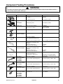
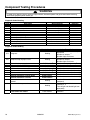
Component Testing Procedures
!
WARNING
To avoid risk of electrical shock, personal injury or death; disconnect power and gas to oven before servicing,
unless testing requires power and/or gas.
Illustration
GND
Component
Spark module
4+0
Test Procedure
Test for voltage at terminals
L and N............................................... 120 VAC
Spark module
2+0
CGL1100AD*
Test for voltage at terminals................... 120 VAC
Holder orifice
Verify gas pressure (WCP) .................... 4" Natural
10" LP/Propane
Check orifice for debris .......................... Clean as needed.
Shut-off Valve
Verify gas supply is turned on.
Gas is turned on.
Shut-off Valve
Model CPL1100AD*
Verify gas supply is turned on.
Gas is turned on.
270° valve
Verify gas is supplied.
Orifice adjusted for Natural or LP.
Input
L or N
Results
Polarity and ground ............................ Not subject to polarity
Spark 270° switch
Spark switch
Model CGL1100AD*
Sealed burner
Open burner
Model CPR1100AD*,
LPR1115AD*,
CP31200AD*,
CG31200AD*
Open burner
Models CPL1100AD*,
CGL1100AD*
Open burner
Model CGR1110AD*
Polarity and ground................................ Not subject to polarity
Adjust set screw for simmer control .......
Unplug switch harness at rear of
range. Test for continuity at wire
terminals.
Switch in LITE position .........................
Switch in any other position..................
Unplug switch harness at rear of
range. Test for continuity at wire
terminals.
Switch in LITE position .........................
Switch in any other position..................
Refer to LP/Nat. conversion instructions.
120 VAC
Continuity
Infinite
120 VAC
Continuity
Infinite
Verify gas is supplied ............................. Gas present.
Check for obstructions or
contamination in burner ports................. Clean/remove any foreign objects.
Check ignitor for bending/cracking.
Verify gas is supplied ............................. Gas present.
Verify air shutter adjusted properly......... Air shutter opening: .400" to .500".
Verify gas is supplied ............................. Gas present.
Verify air shutter adjusted properly......... Air shutter opening: .435" to .565".
Verify gas is supplied ............................. Gas present.
Verify air shutter adjusted properly......... Air shutter opening: .420" to .460".
Pilot burner
Models CPL1100AD*,
CPR1100AD*,
LPR1115AD*,
CP31200AD*,
CG31200AD*
©2004 Maytag Services
Verify pilot selector cartridge is set to
the proper gas........................................ LP or Natural
16023522
15
Component Testing Procedures
!
WARNING
To avoid risk of electrical shock, personal injury or death; disconnect power and gas to oven before servicing,
unless testing requires power and/or gas.
Illustration
M1 Controlled
Component
Oven temperature
adjustment
M1 Controlled
Temperature display
M1 Controlled
Clock Display
M1 Controlled
24 Hour Clock
M1 Controlled
Factory Default
M1 Controlled
Twelve hour off
M1 Controlled
Sabbath Mode
Test Procedure
Press Bake pad.
Enter 550 on the digit-pad.
Immediately press and hold Bake pad
for 3 to 5 seconds.
Oven can be adjusted from -35 to +35
degrees in 5-degree increments by
pressing More + or Less - pads. To
avoid over adjusting the oven, move
temperature 5 degrees each time.
Wait 4 seconds for the data entry
timer to expire to accept the change.
Temperature adjustment is retained
even through a power failure.
Press and hold Cancel and Bake
pads for 3 to 5 seconds. Press
More + or Less - pads to change.
Press and hold Cancel and Clock
pads for 3 to 5 seconds.
Press and hold Cancel and Delay
pads for 3 to 5 seconds. Press
More + or Less - pads to change.
Press and hold Cancel and Keep
Warm pads for 3 to 5 seconds until
beep sounds.
Control will automatically cancel any
cooking operation and remove all relay
drives 12 hours after the last pad
touch.
Hold Clock pad for 3 to 5 seconds to
activate Sabbath mode.
Hold Clock pad for 3 to 5 seconds to
disable Sabbath mode.
Desired bake function must be
initiated before entering Sabbath
mode.
M1 Controlled
M1 Controlled
16
Child lock out
Diagnostic Code
Display
Press and hold Cancel and Cook &
Hold pads for 3 to 5 seconds until
beep sounds.
To reactivate the control, press and
hold Cancel and Cook & Hold pads
for 3 to 5 seconds.
Press and hold More + pad within 60
seconds of powering up the unit.
Cycle through the codes using the
More + or Less - pads.
16023522
Results
While increasing or decreasing oven
temperature, this does not affect selfcleaning temperature.
This mode enables the user to indicate
°F or °C on the display.
Allows clock to be toggled On or OFF.
Allows the time on the clock to be
toggled from 12 hour or 24 hour display.
Allows the clock to be reset to factory
settings.
See Sabbath mode to disable.
"SAb" will be displayed and flash for 5
seconds then remain on until until timedout or cancelled.
The status “SAB” is NOT fault code 5A6.
All pad inputs are disabled except for
CANCEL and CLOCK pads.
This mode disables the normal 12 hour
shutoff to allow operation of the bake
mode for a maximum of 72 hours.
The oven light is not disabled.
This is a safety feature that can be used
to prevent children from accidentally
programming the oven. It disables the
electronic oven control.
Child lockout features must be reset after
a power failure.
The last 5 diagnostic codes will be stored
in the non-volatile memory.
See "Description of Error Codes" for
explanation.
©2004 Maytag Services
Component Testing Procedures
!
WARNING
To avoid risk of electrical shock, personal injury or death; disconnect power and gas to oven before servicing,
unless testing requires power and/or gas.
"Quick Test" Mode for Electronic Range Control
Follow procedure below to use the quick test mode. Entries must be made within 32 seconds of each other or the
control will exit the quick test mode.
1. Press and hold Cancel and Broil pads for 3 seconds.
2. Once the control has entered the "Quick Test" mode, release both pads.
3. Press each of the following pads indicated in the table below.
NOTE:
First time one of following pads are pressed it will activate the response.
The second time the pad is pressed it will deactivate the response.
NOTE:
This mode can only be entered within the first 5 minutes after power up.
NOTE:
If the temperature sensor is greater than 400° F and the "Quick Test" mode will be disabled if the
temperature sensor reaches 400° F while under test.
Display will indicate the following:
Key
[Bake]
[Broil]
[Keep Warm]
[Cook&Hold]
[Clean]
[Delay] (M1)
[Timer]
[Clock]
[More +]
[Less –]
[Cancel]
Operation
Bake relay activated
Broil relay activated
N\A
Last Diagnostic Code displayed
Beep sounds
EEPROM Version Number displayed
Main Code Version Number displayed
All Segments On
Even Segments On
Odd Segments On
End Factory Test Mode
Description of Error Codes
Error diagnostic codes can only be viewed by entering the Diagnostic Code Display Mode.
Each error code is four digits long and is created based on the following table.
Digit
st
1
nd
2
rd
3
th
4
Description
1 – Local to the control circuit board
3 – Sensor or meat probe
4 – Control input
9 – Door lock
Measurable:
d – Diagnostic: measurable parameter
c – Control related, replace control
Secondary System: Sequential numbering
Oven Cavity:
1 – Upper oven (or single cavity oven)
2 – Lower oven
c – Control specific
Primary System:
Diagnostic Code Display Mode may be started only within 60 seconds when powering up the control.
©2004 Maytag Services
16023522
17
Component Testing Procedures
!
WARNING
To avoid risk of electrical shock, personal injury or death; disconnect power and gas to oven before servicing,
unless testing requires power and/or gas.
Diagnostic Code Checking
Code
1c1c
1c2c
1c31
1c6c
1c7c
1c8c
1d11
1d21
3d11
3d21
9d11
Description
Shorted key
Keyboard tail disconnected
Cancel key circuit problem
EEPROM error
Control not calibrated
Cooking program error
Runaway temp (650°F), door unlocked
Runaway temp (950°F), door locked
Sensor open
Sensor shorted
Latch will not lock
When Checked
Always
Always
Always
When accessing EEPROM
Always
Cook or clean programmed
Latch unlocked
Latch locked
Cook or clean active
Cook or clean active
Latch should be locked
Detection
1 minute
1 minute
20 seconds
3 tries
3 tries
3 tries
1 minute
1 minute
20 seconds
20 seconds
See Note 6
Diagnostic Code Handling
Code
Measurable
What is Displayed
Sensor resistance > Infinite Ohms
BAKE flashes
3
Action Taken By Control
Disables audible for affected key
depression
1, 2
Disables all outputs
Disables lights and timers
Disables audible for key depression
1
Disables all outputs
Disables lights and timers
1
Disables all outputs for cavity
1
Disables all outputs
4
Completely disables oven
Cancels active cook function
Disables all cook function for cavity
Disables all cook function for cavity
Disables all cook function for cavity
Sensor resistance > 0 Ohms
Door switch not closed when door is
locked
Door switch not open or closed
BAKE flashes
3
Disables all cook function for cavity
1c1c
Keypress
Nothing
1c2c
Keyboard loop improper value
Nothing
1c31
1c6c
1c7c
1c8c
1d11
1d21
3d11
Cancel key improper value
No response from EEPROM
Calibration value out of range
CRC invalid
Sensor resistance > 2237 Ohms
Sensor resistance > 2787 Ohms
3d21
4d11
4d51
3
BAKE flashes
Nothing
"CAL" in the time digits
Nothing
3
BAKE flashes
3
BAKE flashes
Nothing
Nothing
9d11
18
Lock switch not closed
LOCK flashes
16023522
3
Disables Clean and Lockout
functions 5
Disables Clean and Lockout
functions 4, 5
Turn off light and disable light from
door switch
Disables Clean and Lockout
4
functions
©2004 Maytag Services
Component Testing Procedures
!
WARNING
To avoid risk of electrical shock, personal injury or death; disconnect power and gas to oven before servicing,
unless testing requires power and/or gas.
NOTES:
1
2
3
4
5
6
"Action Taken" applies as long as the condition exists. If the condition goes away, the control recovers.
If there is a cook function or timer active, the function continues. The user cannot edit the function, and [Cancel] will cancel the cook
mode.
Flash rate: 0.2 seconds on, 0.1 second off. Pressing any key will clear the display until the fault clears and is re-triggered.
"Action Taken" applies until there is a POR (Power On Reset ["hard reset"]).
If the control believes the door is locked, unlock it when the function cancels and the cavity temperature cools.
Special conditions for latch faults (9dxx):
•
A known good unlock position is defined as when the unlock switch reads closed and lock switch reads open.
•
A known good lock position is defined as when the unlock switch reads open and lock switch reads closed.
•
A faulted switch means the switch input is reading an invalid state, neither open nor closed.
•
If at POR, the latch is not at a known good unlock position:
•
Affected DLBs (Double Line Breaks) and loads are disabled during detection.
•
If the control is in a known good unlock position and the lock switch becomes faulted:
•
The control will not fault.
•
If a function requiring latch movement is attempted while the lock switch is faulted, the control will sound an error
tone and the function will be disabled.
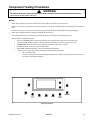
+
_
Bake
Timer
Broil
CANCEL
Cook
Hold
Clean
Delay
Clock
Keep
Warm
Typical M1 Control
©2004 Maytag Services
16023522
19
Disassembly Procedures
!
To avoid risk of electrical shock, personal injury, or death:
disconnect electrical and gas supply before servicing.
WARNING
Removing and Replacing Range
1.
2.
3.
4.
5.
Turn off power to the range at the circuit breaker.
Turn off gas supply line to unit.
Pull the range forward out of the cabinet opening.
Unplug the power cord leading from unit to outlet.
Replace the range using the installation instructions
and anti-tip bracket(s).
Maintop Assembly
1. Turn power off to unit.
2. Remove sealed burners, see "Sealed Burner"
procedure.
3. Remove screws securing main top to orifice holder
assembly.
4. Raise the front edge of the maintop and pull forward.
5. Lift maintop assembly from the oven chassis.
6. Reverse procedure to reinstall maintop assembly.
Front Control Panel
1. Open or remove oven door from unit.
2. Remove control knobs from gas valves, by pulling.
3. Remove screws located on the bottom edge of the
front control panel.
4. Remove control panel by sliding one way or the other
and pulling away from the unit.
5. Reverse procedure to reassemble.
Control Panel
1. Remove maintop assembly, see "Maintop Assembly"
procedure, steps 1 through 4.
2. Remove screws securing control panel heat shield.
3. Remove screws securing bottom outside edges of the
control panel.
4. Pull unit out from the wall far enough to allow the
back outside screws to be loosened.
5. Loosen the back outside screws securing control
panel to backguard.
6. Grasp front lower outside edges of the control panel
and push inward on the outside edges of the
backguard to release the control panel front.
4. Reverse procedure to reinstall control board
assembly.
Rocker Switch
1. Remove control panel, see "Control Panel" procedure
steps 1 through 7.
2. Disconnect and label wire terminals from rocker
switch.
3. Squeeze tabs on rocker switch and push outward to
release from control panel.
4 . Reverse procedure to reinstall indicator light.
Top Surface Valve and Spark Switch
1. Remove front control panel, see "Front Control Panel"
procedure, steps 1 through 4.
2. Remove spark switch by pulling straight off valve.
3. Remove screw securing valve to front manifold.
4. Replace and reassemble in reverse order.
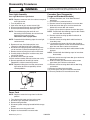
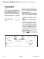
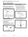
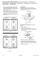
Sealed Burner
1.
2.
3.
4.
Turn off electrical power and gas to the range.
Disconnect gas and power from unit.
Remove grates.
Obtain Burner Wrench (removal and installation tool,
P/N 8312D075-60, see picture below).
5. Place Burner Wrench on burner properly (the wrench
is labeled for proper ignitor alignment).
6. Once the wrench is properly aligned on the burner,
apply steady and even pressure while turning the
wrench counterclockwise. Turn the burner no more
than two inches to loosen.
NOTE: Some minor crunching or grinding sounds may
be heard. This is normal, but be careful not to
chip the finish in visible areas.
7. Once loose, lift the burner straight up and out of the
mounting hole.
8. Label and disconnect wire terminals from burner.
9. Remove screw and washer (securing burner support
to main top) from the burner openings.
10.Replace and reassemble in reverse order.
NOTE: Front edges of the control panel are difficult to
release from backguard.
7. Once the control panel bottom edges are free, pull
control panel forward and raise the control panel
upward to release screws securing top back edges
and allow control panel to tip forward.
8. Reverse procedure to reinstall control panel.
This gap
fits over
the ignitor.
Control Board Assembly
1. Remove control panel, see “Control Panel”
procedure, steps 1 through 7.
2. Remove screws securing control board bracket to
control panel.
3. Label and disconnect terminal plug from control board
assembly.
20
16023522
Ignitor
©2004 Maytag Services
Disassembly Procedures
!
To avoid risk of electrical shock, personal injury, or death:
disconnect electrical and gas supply before servicing.
WARNING
Open Burner
1. Remove maintop assembly, see "Maintop Assembly"
procedure, steps 1, 4 and 5.
2. Remove clip securing burner tubing to surface valve.
3. Lift surface burner and gently move burner up and
toward the rear of the range.
4. Replace and reassemble in reverse order.
Oven Sensor
1. Disconnect power before servicing.
2. Open oven door and remove screws securing sensor
to oven cavity.
NOTE: Gently pull wiring through cavity wall.
5. Maneuver ignitor wire terminal plug through the rear
of the oven cavity.
6. Disconnect ignitor wire terminal plug.
7. Remove screws securing broiler to oven cavity.
8. Carefully maneuver burner off of the broiler orifice
spud and remove from cavity.
9. Remove screws securing ignitor to broiler.
10. Remove wing nut securing flame spreader to broiler.
11. Replace and reassemble in reverse order.
Valve / Regulator Assembly
NOTE: Requires removal of range from installation
position.
1.
2.
3.
4.
5.
6.
7.
3. Disconnect oven sensor at the connector terminal
and remove.
4. Reverse procedure to reinstall sensor.
NOTE: Verify connection is pushed through the
insulation.
Turn off electrical power and gas to the range.
Disconnect gas and power from unit.
Remove nut securing broiler tubing to gas valve.
Remove nut securing bake tubing to gas valve.
Remove screws securing assembly to unit chassis.
Disconnect wires and gas lines to gas valve.
Replace and reassemble in reverse order.
Manual Oven Door Latch Assembly
1. Remove maintop assembly, see "Maintop Assembly"
procedure, steps 1 through 6.
2. Remove screws securing latch assembly to the front
of the oven cavity outer shell.
3. Label and disconnect wire terminals from latch
assembly.
4. Reverse procedure to reinstall door latch assembly.
Bake Burner and Ignitor
1.
2.
3.
4.
5.
Turn off electrical power and gas to the range.
Disconnect gas and power from unit.
Remove oven door and racks.
Remove screws securing bottom bake cover.
Raise the back of the bake burner cover and slide
cover back to release the front edge of cover and lift
out of oven cavity.
6. Remove screws securing bake burner assembly to
the oven chassis.
7. Maneuver bake burner from the burner orifice and out
of the slotted location.
8. Pull forward on assembly to allow the ignitor terminal
plug to pass through the back of the oven cavity.
9. Disconnect terminal plug and remove assembly from
the oven cavity.
10.Remove screws securing ignitor to bake burner.
11. Replace and reassemble in reverse order.
Spark Module
NOTE: Requires removal of range from installation
position.
1. Remove screws securing lower rear access panel.
2. Disconnect and label wire connections from the spark
module.
3. Remove screws securing spark module to unit
chassis.
4. Replace and reverse procedure to reassemble.
Oven Door Removal
!
WARNING
To avoid risk of personal injury or property damage,
do not lift oven door by the handle.
Broil Burner and Ignitor
1.
2.
3.
4.
Turn off electrical power and gas to the range.
Disconnect gas and power from unit.
Remove oven door, and racks.
Remove screws securing ignitor wire plate cover to
back of the oven cavity.
©2004 Maytag Services
1. Open oven door and place door hinge locking device
into lock position.
2. Place oven door in first stop position, then grasp both
sides and lift up off the hinges.
3. Reverse procedure to reinstall oven door.
16023522
21
Disassembly Procedures
!
WARNING
To avoid risk of electrical shock, personal injury, or death:
disconnect electrical and gas supply before servicing.
Oven Door Hinge Receiver
Storage Drawer Track Removal
1. Turn off power to unit.
2. Remove oven door, see "Oven Door Removal"
procedure.
3. Remove maintop assembly, see "Maintop Assembly"
procedure, steps 1 through 5.
4. Remove side panel, see "Side Panel Removal"
procedures.
5. Remove the top and bottom screws securing hinge
assembly to the front frame.
6. Remove hinge from oven chassis.
7. Reverse procedure to reinstall oven door hinge.
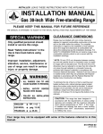
1. Remove the storage drawer by pulling it out to the
fully open or stop position, lifting the drawer at the
rear to disengage the drawer track rollers from the
drawer runners, and sliding the drawer out of the
range.
2. The tracks are mounted to a rear support and the
frame of the range. Remove the two track mounting
screws and remove the track. If the track support is
being replaced, remove the mounting screw securing
it to the side frame and remove the support.
Side Panel Removal
1. Pull warming drawer out as far as it will go.
2. Located on each side of the track is a plastic lever
inside the track location. Push the left side down and
the right side up to release slide from track and pull
forward.
3. When installing warming drawer, align slide with track
and push warming drawer into place.
1. Turn off power to unit.
2. Remove oven door, see "Oven Door Removal"
procedure.
3. Remove maintop assembly, see "Maintop Assembly"
procedure, steps 1 through 5.
4. Remove screws securing lower rear galvanized cover
from unit.
5. Remove screws securing top and back of side panel.
6. Pull rear of side panel away from range then slide
side panel forward to release from side panel
spacers.
7. Reverse procedure to reinstall side panel.
Backguard
NOTE: Requires removal of oven from installation
position.
1. Remove maintop assembly, see "Maintop Assembly"
procedure, steps 1 through 6.
2. Remove screws securing upper back panel form unit.
3. Remove screws securing bottom outside edges of the
backguard to unit chassis.
4. Reverse procedure to reinstall backguard.
Storage Drawer Removal
1. Pull drawer straight out to first stop. Lift the front and
pull out to second stop.
2. Let front of door rest on floor. Place hands toward
back of drawer and lift it out.
Warming Drawer Removal
Warming Drawer Element
1. Remove warming drawer, See "Warming Drawer
Removal" procedure, steps 1 and 2.
2. Remove screws securing element to bottom and
back of chassis.
3. Pull element forward until element end are through
the back of the unit.
4. Disconnect wire terminal from element.
5. Reverse procedure to reinstall element.
Convenience Outlet/Circuit Breaker
(Canadian Models)
1. Remove control panel, see "Control Panel" procedure
for removal.
2. Label and disconnect wire terminals from
convenience outlet and/or circuit breaker.
3. Remove screws securing outlet and/or circuit breaker
to backguard and push outward to release.
4 . Reverse procedure to reinstall convenience outlet
and/or circuit breaker.
3. To replace:
a. Place the set of rollers on the drawer behind the
set of rollers on the oven. (As shown above.)
b. Align the guides and push the drawer back into
position.
22
16023522
©2004 Maytag Services
Disassembly Procedures
!
To avoid risk of electrical shock, personal injury, or death:
disconnect electrical and gas supply before servicing.
WARNING
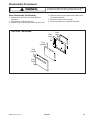
Frameless Door Disassembly
(Large and Standard Windows)
Oven Light Assembly
Oven Light Bulb/Oven Light Socket
NOTE: Requires removal of unit from cabinet to replace
oven light socket.
1.
2.
3.
4.
Turn off power to unit.
Open oven door to gain access to oven light.
Unscrew (counterclockwise) glass knurled dome.
Unscrew (counterclockwise) oven light bulb.
NOTE: To avoid damaging the new bulb and
decreasing life of the bulb, do not touch new
bulb with bare hands or fingers.
Hold with a cloth or paper towel.
1. Remove oven door, see "Oven Door Removal"
procedure.
2. Place door on a protected surface.
3. Remove screws securing bottom trim to oven door.
4. Slide outer oven door glass and trim towards the
bottom of the oven door and remove.
5. Detach right and left trim pieces for outer door glass.
NOTE: Proceed with the following steps for door handle
and inner door disassembly.
NOTE: Proceed with the following steps for oven light
socket removal.
5. Remove unit from installation position, see
“Removing and Replacing Oven” procedure.
6. Disconnect or unplug the power cord leading from
unit to fuse box or junction box depending on unit.
7. Remove screws securing back cover and remove.
8. Carefully displace fiberglass insulation away from
rear of light socket.
9. Disconnect wires from light socket.
10.Push socket assembly inwards into the oven cavity.
11. Reverse procedure to reinstall light socket.
Reposition insulation around lamp socket.
NOTE: Reposition fiberglass insulation around oven
light socket to eliminate possibility of heat
related problems.
6. Remove screws securing top door handle trim to
oven door chassis.
7. Remove screws securing door handle brackets to
inner door panel.
8. Lift upward on the lower side of the door handle to
release side alignment screws and rotate towards the
top of the oven door to release and remove.
9. Remove screws securing door handle to door handle
brackets.
NOTE: Proceed with the following steps for inner door
disassembly.
10. Remove screws securing lower door glass retainer to
door baffle and remove.
11 Slide inner door glass downward to release from
upper door glass retainers and remove.
12. Remove screws securing door baffle to door lining
and remove.
13. Remove insulation from oven door.
14. Lift inner glass and glass frame from oven door.
15. Reverse procedure to reassemble oven door.
Power Cord
NOTE: Requires removal of range from installation
position.
1.
2.
3.
4.
Turn off electrical power and gas to the range.
Disconnect gas and power cord from unit.
Remove storage drawer.
Disconnect power cord plug located behind storage
drawer.
5. Remove screw securing cord to unit.
6. Replace and reassemble in reverse order.
©2004 Maytag Services
16023522
23
Disassembly Procedures
!
To avoid risk of electrical shock, personal injury, or death:
disconnect electrical and gas supply before servicing.
WARNING
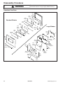
Frameless Oven Door
Door
Seal
Door
Lining
Door
Insulation
Standard Window
Inner
Glass
Door
Baffle
Large Window
Door
Glass
Support
Door
Glass
Clip
Door
Glass
Door
Lining
Window
Gasket
Inner
Glass
Door
Panel
Glass
Frame
Door
Baffle
Door
Handle
Top
Door
Trim
Door
Trim
Inner
Door
Glass
Door
Insulation
Door
Gasket
Door
Glass
Retainer
Door
Handle
Glass
Support
Door
Trim
Outer
Door
Glass
24
16023522
©2004 Maytag Services
Disassembly Procedures
!
To avoid risk of electrical shock, personal injury, or death:
disconnect electrical and gas supply before servicing.
WARNING
Door Disassembly (No Window)
1. Remove oven door, see "Oven Door Removal"
procedure.
2. Place door on a protected surface.
3. Remove screws securing door handle to door panel.
4. Remove screws securing door panel to door lining
and remove door liner.
5. Remove insulation from oven door.
6. Reverse procedure to reassemble oven door.
Oven Door - No Window
Door
Lining
Door
Seal
Door
Insulation
Door
Handle
Door
Panel
©2004 Maytag Services
16023522
25
Appendix A
A–1
16023522
©2004 Maytag Services
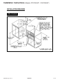
Installation Instructions
(Models CP31200AD*, CG31200AD*)
-2-
©2004 Maytag Services
16023522
A– 2
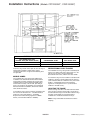
Installation Instructions
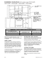
(Models CP31200AD*, CG31200AD*)
9,200 BTU/HR OR LESS
0 INCHES
3 INCHES (7.6 CM)
MORE THAN 9,200 BTU/HR
1 INCH (2.5 CM)
3 INCHES (7.6 CM)
Check the range model number plate to see if the range is
approved for installation in mobile homes and/or
recreational park trailers. If approved the following items
are applicable.
The installation of a range designed for recreational park
trailers must conform with state or other codes or, in the
absence of such codes, with the Standard for
Recreational Park Trailers, ANSI A119.5-latest edition.
In Canada the range must be installed in accordance with
CAN/CSA - Z240.6.2 - Electrical Requirements for R.V.’s
(CSA Standard CAN/CSA - Z240 RV Series) and Section
Z240.4.2 - Installation Requirements for Propane
Appliances and Equipment in R.V.’s (CSA Standard
CAN/CSA - Z240 RV Series).
The installation of a range designed for mobile home
installation must conform with the Manufactured Home
Construction and Safety Standard, Title 24 CFR, Part
3280 [formerly the Federal Standard for Mobile Home
Construction and Safety, Title 24 HUD, (Part 280)] or,
when such standard is not applicable, the Standard for
Manufactured Home Installations, ANSI A225.1/NFPA
501A, or with local codes.
Do not set range over holes in the floor or other locations
where it may be subject to strong drafts. Any opening in
the wall behind the range and in the floor under the range
should be sealed. Make sure the flow of cooling/
ventilation air is not obstructed below the range.
In Canada the range must be installed in accordance with
the current CSA Standard C22.1 - Canadian Electrical
Code Part 1 and Section Z240.4.1 - Installation
Requirements for Gas Burning Appliances in Mobile
Homes (CSA Standard CAN/CSA - Z240MH).
A range should NOT be installed over kitchen
carpeting.
-3-
A–3
16023522
©2004 Maytag Services
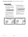
Installation Instructions
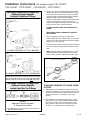
(Models CPL1100AD*, CGL1100AD*)
INSTALLATION
RECREATIONAL PARK TRAILERS
Check the range model number plate to see if the range is
approved for installation in mobile homes and/or
recreational park trailers. If approved the following items
are applicable.
The installation of a range designed for recreational park
trailers must conform with state or other codes or, in the
absence of such codes, with the Standard for
Recreational Park Trailers, ANSI A119.5-latest addition.
MOBILE HOMES
In Canada the range must be installed in accordance with
Section C22.2 No. 148/CAN/CSA - Z240.6.2 - Electrical
Requirements for R.V.’s (CSA Standard CAN/CSA - Z240
RV Series) and Section Z240.4.2 - Installation
Requirements for Propane Appliances and Equipment in
R.V.’s (CSA Standard CAN/CSA - Z240 RV Series).
The installation of a range designed for mobile home
installation must conform with the Manufactured Home
Construction and Safety Standard, Title 24 CFR, Part
3280 (formerly the Federal Standard for Mobile Home
Construction and Safety, Title 24 HUD, Part 280) or, when
such standard is not applicable, the Standard for
Manufactured Home Installations ANSI A225.1/NFPA
501A, or with local codes.
REMOVAL OF SHIPPING & PACKING
a. Using carton corner posts (4), folded flat and stacked
two high to protect floor, lay range on its back.
Remove the four screws which attach skid to base of
range.
In Canada the range must be installed in accordance with
the current CSA Standard C22.1 - Canadian Electrical
Code Part 1 and Section Z240.4.1 - Installation
Requirements for Gas Burning Appliances in Mobile
Homes (CSA Standard CAN/CSA - Z240MH).
b. Stand range upright.
c. Remove all packing material, tape and protective film
on some chrome plated or stainless steel parts before
range is installed.
INSTALLATION DRAWINGS
-2©2004 Maytag Services
16023522
A– 4
Installation Instructions
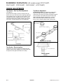
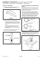
(Models CPL1100AD*, CGL1100AD*)
INSTALLATION DRAWINGS
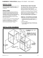
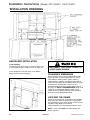
BACKGUARD INSTALLATION
(if not installed)
The backguard fits on the range as shown in figure 1 and
is secured with a bracket, 2 bolts and nuts on each side.
DISCONNECT ELECTRICAL POWER TO
AVOID SHOCK HAZARD.
Set the backguard on the rear of the range. Bolt the
backguard to the end panel flanges.
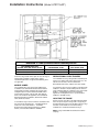
CLEARANCE DIMENSIONS
All free-standing ranges can be installed with the back
against (0 inches) a vertical combustible wall, and the
sides below the cooking surface against (0 inches)
combustible base cabinets. For complete information in
regard to the installation of wall cabinets above the range
and clearances to combustible surfaces see the
installation drawings and/or the model number plate on
the range. For SAFETY CONSIDERATIONS do not install
a range in any combustible cabinetry which is not in
accord with the installation drawings and the clearance
given on the range Model Number Plate.
LOCATING THE RANGE
Do not set range over holes in the floor or other locations
where it may be subject to strong drafts. Any opening in
the wall behind the range and in the floor under the range
should be sealed. Make sure the flow of
cooling/ventilation air is not obstructed below the range.
FIGURE 1
NOTE: A range should NOT be installed directly over
kitchen carpeting.
-3-
A–5
16023522
©2004 Maytag Services
Installation Instructions
(Model LPR1115AD*)
:$51,1*
7+,6 352'8&7 6+28/' 127 %( ,167$//('
%(/2: $ 9(17,/$7,21 7<3( +22' 6<67(0
7+$7 ',5(&76 $,5 ,1 $ '2:1:$5'
',5(&7,21
6(( ),*85(
7+(6( 6<67(06 0$< &$86( ,*1,7,21 $1'
&20%867,21 352%/(06 :,7+ 7+( *$6
%851(56 5(68/7,1* ,1 3(5621$/ ,1-85<
$1' 0$< $))(&7 7+( &22.,1*
3(5)250$1&( 2) 7+( 81,7
127( 7+( ),*85( 0$< 127 $&&85$7(/<
5(35(6(17 <285 5$1*( 25 &22.723
+2:(9(5 7+,6 :$51,1* $33/,(6 72 $//
*$6 &22.,1* 352'8&76
-2-
©2004 Maytag Services
16023522
A– 6
Installation Instructions
(Model LPR1115AD*)
9,200 BTU/HR OR LESS
0 INCHES
3 INCHES (7.6 CM)
MORE THAN 9,200 BTU/HR
1 INCH (2.5 CM)
3 INCHES (7.6 CM)
Check the range model number plate to see if the range is
approved for installation in mobile homes and/or
recreational park trailers. If approved the following items
are applicable.
The installation of a range designed for recreational park
trailers must conform with state or other codes or, in the
absence of such codes, with the Standard for
Recreational Park Trailers, ANSI A119.5-latest edition.
In Canada the range must be installed in accordance with
CAN/CSA - Z240.6.2 - Electrical Requirements for R.V.’s
(CSA Standard CAN/CSA - Z240 RV Series) and Section
Z240.4.2 - Installation Requirements for Propane
Appliances and Equipment in R.V.’s (CSA Standard
CAN/CSA - Z240 RV Series).
The installation of a range designed for mobile home
installation must conform with the Manufactured Home
Construction and Safety Standard, Title 24 CFR, Part
3280 [formerly the Federal Standard for Mobile Home
Construction and Safety, Title 24 HUD, (Part 280)] or,
when such standard is not applicable, the Standard for
Manufactured Home Installations, ANSI A225.1/NFPA
501A, or with local codes.
Do not set range over holes in the floor or other locations
where it may be subject to strong drafts. Any opening in
the wall behind the range and in the floor under the range
should be sealed. Make sure the flow of cooling/
ventilation air is not obstructed below the range.
In Canada the range must be installed in accordance with
the current CSA Standard C22.1 - Canadian Electrical
Code Part 1 and Section Z240.4.1 - Installation
Requirements for Gas Burning Appliances in Mobile
Homes (CSA Standard CAN/CSA - Z240MH).
A range should NOT be installed over kitchen
carpeting.
-3-
A–7
16023522
©2004 Maytag Services
Installation Instructions
(All models except CPL1100AD*,
CGL1100AD*, CP31200AD*, CG31200AD*, LPR1115AD*)
-2©2004 Maytag Services
16023522
A– 8
Installation Instructions
(All models except CPL1100AD*,
CGL1100AD*, CP31200AD*, CG31200AD*, LPR1115AD*)
9,200 BTU/HR OR LESS
0 INCHES
3 INCHES (7.6 CM)
MORE THAN 9,200 BTU/HR
1 INCH (2.5 CM)
3 INCHES (7.6 CM)
Check the range model number plate to see if the range is
approved for installation in mobile homes and/or
recreational park trailers. If approved the following items
are applicable.
The installation of a range designed for recreational park
trailers must conform with state or other codes or, in the
absence of such codes, with the Standard for
Recreational Park Trailers, ANSI A119.5-latest edition.
In Canada the range must be installed in accordance with
CAN/CSA - Z240.6.2 - Electrical Requirements for R.V.’s
(CSA Standard CAN/CSA - Z240 RV Series) and Section
Z240.4.2 - Installation Requirements for Propane
Appliances and Equipment in R.V.’s (CSA Standard
CAN/CSA - Z240 RV Series).
The installation of a range designed for mobile home
installation must conform with the Manufactured Home
Construction and Safety Standard, Title 24 CFR, Part
3280 [formerly the Federal Standard for Mobile Home
Construction and Safety, Title 24 HUD, (Part 280)] or,
when such standard is not applicable, the Standard for
Manufactured Home Installations, ANSI A225.1/NFPA
501A, or with local codes.
Do not set range over holes in the floor or other locations
where it may be subject to strong drafts. Any opening in
the wall behind the range and in the floor under the range
should be sealed. Make sure the flow of cooling/
ventilation air is not obstructed below the range.
In Canada the range must be installed in accordance with
the current CSA Standard C22.1 - Canadian Electrical
Code Part 1 and Section Z240.4.1 - Installation
Requirements for Gas Burning Appliances in Mobile
Homes (CSA Standard CAN/CSA - Z240MH).
A range should NOT be installed over kitchen
carpeting.
-3-
A–9
16023522
©2004 Maytag Services
Installation Instructions
(All models except CPL1100AD*,
CGL1100AD*, CP31200AD*, CG31200AD*, LPR1115AD*)
h. Apply a non-corrosive leak detection fluid to all joints
and fittings in the gas connection between the supply
line shut-off valve and the range. Include gas fittings
and joints in the range if connections were disturbed
during installation. Check for leaks! Bubbles
appearing around fittings and connections will indicate
a leak. If a leak appears, turn off supply line gas
shut-off valve, tighten connections, turn on the supply
line gas shut off valve, and retest for leaks.
*DV 6XSSO\ &RQQHFWLRQV )RU 5DQJHV :LWK
$SSOLDQFH 3UHVVXUH 5HJXODWRU
/RFDWHG ,Q 7KH %RWWRP 2I 5DQJH
i.
Remove shipping screw from ALL top burners.
(Conventional top burner models only). This is to hold
the burners in place on the burner bracket for shipping
purposes only. (See figure 5).
j.
Adjust burner air shutter to the widest opening that will
not cause the flame to lift or blow off the burner when
cold.
72 &211(&7 *$6 6833/< 72 2 137 0$/( ,1/(7
Correctly adjusted sealed burners, can have
flames that will lift or blow off without a pot over the
burner. These should be adjusted with a pot in place.
72 &211(&7 *$6 6833/< 72 2 137 )(0$/( ,1/(7
WHEN THE INSTALLER HAS COMPLETED INSTALLATION
OF THE APPLIANCE, LEAVE THE APPLIANCE PRESSURE
REGULATOR SHUT-OFF VALVE IN THE POSITION.
cfdrob R
*DV 6XSSO\ &RQQHFWLRQ )RU 5DQJHV :LWK
$SSOLDQFH 3UHVVXUH 5HJXODWRU
/RFDWHG 8QGHU 0DLQ 7RS 2I 5DQJH
3. The appliance and its individual shutoff valve must be
disconnected from the gas supply piping system during
any pressure testing of that system at test pressures in
excess of 1/2 lbs./sq. in. (3.5 kPa) (13.8 in. water
column).
4. The appliance must be isolated from the gas supply
piping system by closing its individual manual shutoff
valve during any pressure testing of the gas supply
piping system at test pressures equal to or less than
1/2 lbs./sq. in. (3.5 kPa) (13.8 in. water column).
cfdrob Q
Appliance Pressure Regulator
& Alternate Connectors
The appliance pressure regulator on your range may
differ from this illustration.
-6©2004 Maytag Services
16023522
A– 10
Installation Instructions
(All models except CPL1100AD*,
CGL1100AD*, CP31200AD*, CG31200AD*, LPR1115AD*)
!" #$%'!* +, !" '-!% /02,%3#*%
!" 24*#4 /02,%3#*%
(See figure 6)
-- !" 24*#4 +-6#, The approximate height of the
flame at the high or full-on position is shown below.
Purge all air from supply system by turning on one top
burner valve. Then turn off valve and adjust top pilot flame
using adjusting screw “A” (figure 6) so that flame is even
with top of flash tube. To light the burner, push and turn
top burner knob to the lite position. NOTE: Some models
have ONLY one pilot adjustment at the manifold pipe.
Adjust burner air shutter to the widest opening that will not
cause the flame to lift or blow off the burner when cold.
NOTE: Correctly adjusted sealed burners, can have
flames that will lift or blow off without a pot over the
burner. These should be adjusted with a pot in place.
3/4² FLAME
cfdrob S
!" #$%'!* -#$%4'$ 5*'%'!*
To operate, push and turn top burner knob to the LITE
position. The top burner will light. To turn OFF spark after
the top burner has ignited turn knob to HI setting.
cfdrob T
-7-
A–11
16023522
©2004 Maytag Services
Installation Instructions
(All models except CPL1100AD*,
CGL1100AD*, CP31200AD*, CG31200AD*, LPR1115AD*)
#3!6'*5 #+-#/ 24*#4 !4 /02,%3#*% 4
#46'$#
'4 72%%#4 6#* 24*#4
a. The approximate length of the flame of oven burner is
a 1/2 inch distinct inner blue flame, figure 8.
Mark ignitor location relative to main top with pencil. This
mark on the main top is used as a reference point when
replacing the burner assembly to insure that the burner is
tightened to its original position.
Place burner wrench (part no. 8312D075-60, available
from your dealer or authorized service agency) over
surface burner assembly with ignitor positioned inside gap
in wrench ring (figure 10). This prevents ignitor from being
crushed when wrench tightens on burner assembly.
Rotate burner assembly approximately one-eighth turn
counter-clockwise and lift from main top (figure 11).
cfdrob U
b. Oven burner flame can be checked as follows:
1. Yellow flame on burner - open burner air shutter
to the widest opening that will not cause the flame
to lift or blow off the burner when cold. (See #2 on
figure 9).
2. Distinct blue flame but lifting - close burner air
shutter to the point where it will not cause the
flame to lift or blow off the burner when cold. (See
#2 on figure 9).
c.
The oven burner air shutter adjustment is the same on
ranges with a gas pilot or electric ignition.
cfdrob NM
! #+,,#38-# Replace burner assembly in main top
and rotate approximately one-eighth turn clockwise using
burner wrench until burner locks into position with ignitor
aligned with reference mark on main top.
cfdrob V
cfdrob NN
-8©2004 Maytag Services
16023522
A– 12
Appendix B
B–1
16023522
©2004 Maytag Services
Use Instructions
©2004 Maytag Services
(Models CP/CG31200AD*, CPL1100AD*, CGL1100AD*)
16023522
B–2
Use Instructions
B–3
(Models CP/CG31200AD*, CPL1100AD*, CGL1100AD*)
16023522
©2004 Maytag Services
Use Instructions
(Models CPR1100AD*, CGR1110AD*, CGL1100AD*,
CGR1415AD*, CGR1425AD*, CGR3725AD*, CP31200AD*, CG31200AD*,
CG31400AD*, CP31600AD*, CG31600AD*, CG34800AD*)
Surface Cooking
High: Use to bring liquid to a boil, or reach
pressure in a pressure cooker. Always
reduce setting to a lower heat when liquids
begin to boil or foods begin to cook.
Low: Use to simmer foods, keep foods
warm and melt chocolate or butter. Some
cooking may take place on the Low
setting if the pan is covered.
Med: An intermediate flame size is used to
continue cooking. Food will not cook any
faster when a higher flame setting is used
than needed to maintain a gentle boil.
Water boils at the same temperature
whether boiling gently or vigorously.
To light pilot:
Surface Controls
Raise the cooktop and hold a
lighted match near the pilot
ports (See illustration). There
are two pilot ports, one on the
right side and one on the left
side.
CAUTION
• If flame should go out during a cooking operation, turn
the burner off. If a strong gas odor is detected, open a
window and wait five minutes before relighting the
burner.
Conventional
Gas Burner
• Be sure all surface controls are set in the OFF position
prior to supplying gas to the range.
• NEVER touch cooktop until it has cooled. Expect some
parts of the cooktop, especially around the burners, to
become warm or hot during cooking. Use potholders to
protect hands.
Surface Control Knobs
Use to turn on the surface burners. An infinite choice of heat
settings is available from Low to High. At the High setting a
detent or notch may be felt. The knobs can be set on or
between any of the settings.
Pilotless Ignition (select models)
Graphics next to the knob identify which burner the
knob controls. For example, the graphic at left shows
the left front burner location.
Pilotless ignition eliminates the need for a constant standing
pilot light. Each sealed burner has a spark ignitor. When
cleaning around the surface burner use care. If cleaning cloth
should catch the ignitor, it could be damaged preventing
ignition.
If the surface burner does not
light, check if ignitor is
broken, soiled or wet. If
clogged, clean the
small port beneath
the ignitor
PORTS
using a straight
pin.
Setting the controls:
The size and type of cookware will affect the heat setting. For
information on cookware and other factors affecting heat
settings, refer to “Cooking Made Simple” booklet.
BURNER HEAD
CAP
1. Place a pan on the burner grate.
• The burner flame may lift off or appear separated from
the port if a pan is not placed on the grate.
2. Push in and turn the knob counterclockwise to the Lite
setting.
IGNITOR
• A clicking (spark) sound will be heard and the burner
PORT BELOW IGNITOR
will light. (All four ignitors will spark when any surface
burner knob is turned to the Lite position.)
Pilot Ignition (select models)
3. After the burner lights, turn knob to desired flame size.
When the range is first installed, the standing pilots may be
difficult to light due to air in the gas line. To bleed off air from
the line, hold a lighted match next to the burner and turn the
knob on. When the burner lights, turn the knob off and
proceed as directed below.
• The ignitor will continue to spark until the knob is
turned past the Lite position.
5
©2004 Maytag Services
16023522
B–4
Use Instructions
(Models CPR1100AD*, CGR1110AD*, CGL1100AD*,
CGR1415AD*, CGR1425AD*, CGR3725AD*, CP31200AD*, CG31200AD*,
CG31400AD*, CP31600AD*, CG31600AD*, CG34800AD*)
Oven Cooking
Manual Clean Oven Control
(select models)
A
B
C
D
E
F
NOTE: The display will show 12:00 when the appliance is first connected to power or if power is interrupted. The Bake and Broil
indicators light when function is pressed.
2. Set the correct time of day using the ▲ or ▼ pads. If the
▲ or ▼ pad is not pressed within 30 seconds, the program
will cancel. Press the CLOCK pad and begin again.
A
B
BAKE
BROIL
Use for baking and roasting.
Use for broiling and top browning.
C
TIMER
Sets timer.
D
CLOCK
Use to set time-of-day clock.
E
CANCEL
Cancels all operations except timer
and clock.
F
▲ (More) or
▼ (Less)
Enters or changes time, oven
temperature. Sets HI or LO broil.
Setting the Timer
The timer can be set from one minute (:01) up to 99 hours
and 59 minutes (99:59). Time will be displayed in minutes and
not in seconds. THE TIMER DOES NOT CONTROL THE
OVEN.
1. Press the TIMER pad.
Using the Touchpads
• 0:00 will light and the colon (:) will flash in
the display.
• Press the desired pad.
2. Press the ▲ or ▼ pad until the desired time is displayed.
• Press the ▲ or ▼ pad to enter time or temperature.
• The timer will begin as soon as the time is set.
• A beep will sound each time a function pad is pressed. There
is no beep for the ▲ or ▼ pad.
• The flashing colon indicates that a timing operation is in
progress. (The colon will not flash if the time of day or
oven temperature is displayed.)
• A double beep will sound if a programming error occurs.
• Two short beeps signal the end of the operation. “0:00”
will appear in the display.
Note: Four seconds after pressing the ▲ or ▼ pad, the
time or temperature will automatically be entered. If more
than 30 seconds elapse between touching a function pad
and the ▲ or ▼ pad, the function will be canceled and the
display will return to the previous display.
• If desired, press the CLOCK pad and the time of day will
briefly reappear in the display during a timing operation.
• If desired, press the BAKE or BROIL pads and the
current temperature setting will briefly reappear in the
display during a timing operation.
Setting the Clock
1. Press the CLOCK pad.
To cancel the timer operation:
• The clock time cannot be set if the control is programmed for a bake, broil or timing operation.
Press and hold the TIMER pad for several seconds.
7
B–5
16023522
©2004 Maytag Services
Use Instructions
(Models CPR1100AD*, CGR1110AD*, CGL1100AD*,
CGR1415AD*, CGR1425AD*, CGR3725AD*, CP31200AD*, CG31200AD*,
CG31400AD*, CP31600AD*, CG31600AD*, CG34800AD*)
Oven Cooking
Self-Clean Oven Control (select models)
A
B
E
F
G
H
C
D
I
J
The control panel is designed for ease in programming. The display window on the control shows time of day, timer and oven functions.
Control panel shown includes model specific features. (Styling may vary depending on model.)
A
BROIL
Use for broiling and top browning.
Clock
B
BAKE
Use for baking and roasting.
C
More (▲) or
Less (▼)
Enters or changes time, oven
temperature. Sets HI or LO broil.
The clock can be set to display time in a 12-hour or 24-hour
format. The clock is set at the factory for the 12-hour format.
D
E
TIMER
COOK & HOLD
Sets timer.
Bakes for a preset time, then holds food
warm for 1 hour.
1. Press and hold the CANCEL and DELAY
pads for three seconds.
F
CLEAN
Use to set self-clean cycle.
G
DELAY
Programs the oven to start baking at
a later time.
3. Set the time of day following the
directions below.
H
I
CLOCK
KEEP WARM
Use to set time of day clock.
Use to keep cooked food warm in oven.
J
CANCEL
Cancels all operations except timer
and clock.
To change the clock to 24-hour format:
2. Press ▲ or ▼ to select 12 or 24 hour.
To set the Clock:
1. Press the CLOCK pad.
• Time of day and colon flash in the
display.
2. Press ▲ or ▼ to set the time of day.
• Colon continues flashing.
Using the Touchpads
3. Press the CLOCK pad again or wait four
seconds.
• Press the desired pad.
When electrical power is supplied or after a power
interruption, the last clock time before power was
interrupted will flash.
• Press the ▲ or ▼ to enter time or temperature.
• A beep will sound when any pad is touched.
To recall the time of day when another time function is
showing, press the CLOCK pad.
• A double beep will sound if a programming error occurs.
Note: Four seconds after pressing the ▲ or ▼ pads, the
time or temperature will automatically be entered. If more
than 30 seconds elapse between touching a function pad
and the ▲ or ▼ pads, the function will be canceled and
the display will return to the previous display.
Clock time cannot be changed when the oven has been
programmed for cook or clean Delay or Cook & Hold.
cont.
10
©2004 Maytag Services
16023522
B–6
Use Instructions
(Models AGR4400AD*, AGR4412AD*, AGR5712AD*,
MGR4451AD*, MGR4452AD*, MGR5751AD*, MGR5752AD*, PGR4420LD*,
PGR5720LD*)
Surface Cooking
High: Use to bring liquid to a boil, or reach
pressure in a pressure cooker. Always
reduce setting to a lower heat when liquids
begin to boil or foods begin to cook.
Low: Use to simmer foods, keep foods
warm and melt chocolate or butter. Some
cooking may take place on the Low
setting if the pan is covered.
An intermediate flame size is used to
continue cooking. Food will not cook any
faster when a higher flame setting is used
than needed to maintain a gentle boil.
Water boils at the same temperature
whether boiling gently or vigorously.
Surface Controls
Graphics next to the knob identify which burner the
knob controls. For example, the graphic at left shows
the left front burner location.
CAUTION
Setting the controls:
• If flame should go out during a cooking operation, turn
the burner off. If a strong gas odor is detected, open a
window and wait five minutes before relighting the
burner.
The size and type of cookware will affect the heat setting. For
information on cookware and other factors affecting heat
settings, refer to “Cooking Made Simple” booklet.
1. Place a pan on the burner grate.
• Be sure all surface controls are set in the OFF position
prior to supplying gas to the range.
• The burner flame may lift off or appear separated from
the port if a pan is not placed on the grate.
• NEVER touch cooktop until it has cooled. Expect some
parts of the cooktop, especially around the burners, to
become warm or hot during cooking. Use potholders to
protect hands.
2. Push in and turn the knob counterclockwise to the Light
setting.
• A clicking (spark) sound will be heard and the burner
will light. (All four ignitors will spark when any surface
burner knob is turned to the Light position.)
Pilotless Ignition
Pilotless ignition eliminates the need for a constant standing
pilot light. Each sealed burner has a spark ignitor. When
cleaning around the surface burner use care. If cleaning cloth
should catch the ignitor, it could be damaged preventing
ignition.
3. After the burner lights, turn knob to desired flame size.
If the surface burner does not
light, check if ignitor is
broken, soiled or wet. If
clogged, clean the
small port beneath
the ignitor
PORTS
using a straight
pin.
Operating During a
Power Failure
• The ignitor will continue to spark until the knob is
turned past the Light position.
BURNER HEAD
CAP
CAUTION
When lighting the surface burners, be sure all of the
controls are in the OFF position. Strike the match first and
hold it in position before turning the knob to Light.
IGNITOR
PORT BELOW IGNITOR
1. Hold a lighted match to the desired surface burner head.
Surface Control Knobs
2. Push in and turn the control knob slowly to Light.
Use to turn on the surface burners. An infinite choice of heat
settings is available from Low to High. At the High setting a
detent or notch may be felt. The knobs can be set on or
between any of the settings.
3. Once lit, adjust the flame to the desired level.
5
B–7
16023522
©2004 Maytag Services
Use Instructions
(Models AGR4400AD*, AGR4412AD*, AGR5712AD*,
MGR4451AD*, MGR4452AD*, MGR5751AD*, MGR5752AD*, PGR4420LD*,
PGR5720LD*)
Oven Cooking
Manual Clean Oven Control
(select models)
A
B
C
D
E
F
NOTE: The display will show 12:00 when the appliance is first connected to power or if power is interrupted. The Bake and Broil
indicators light when function is pressed.
2. Set the correct time of day using the ▲ or ▼ pads. If the
▲ or ▼ pad is not pressed within 30 seconds, the program
will cancel. Press the Clock pad and begin again.
A
B
Bake
Broil
Use for baking and roasting.
Use for broiling and top browning.
C
Timer
Sets timer.
D
Clock
Use to set time-of-day clock.
E
Cancel
Cancels all operations except timer
and clock.
F
▲ (More) or
▼ (Less)
Enters or changes time, oven
temperature. Sets HI or LO broil.
Setting the Timer
The timer can be set from one minute (:01) up to 99 hours
and 59 minutes (99:59). Time will be displayed in minutes and
not in seconds. THE TIMER DOES NOT CONTROL THE
OVEN.
1. Press the Timer pad.
Using the Touchpads
• 0:00 will light and the colon (:) will flash in
the display.
• Press the desired pad.
2. Press the ▲ or ▼ pad until the desired time is displayed.
• Press the ▲ or ▼ pad to enter time or temperature.
• The timer will begin as soon as the time is set.
• A beep will sound each time a function pad is pressed. There
is no beep for the ▲ or ▼ pad.
• The flashing colon indicates that a timing operation is in
progress. (The colon will not flash if the time of day or
oven temperature is displayed.)
• A double beep will sound if a programming error occurs.
• Two short beeps signal the end of the operation. “0:00”
will appear in the display.
Note: Four seconds after pressing the ▲ or ▼ pad, the
time or temperature will automatically be entered. If more
than 30 seconds elapse between touching a function pad
and the ▲ or ▼ pad, the function will be canceled and the
display will return to the previous display.
• If desired, press the Clock pad and the time of day will
briefly reappear in the display during a timing operation.
• If desired, press the Bake or Broil pads and the current
temperature setting will briefly reappear in the display
during a timing operation.
Setting the Clock
1. Press the Clock pad.
To cancel the timer operation:
• The clock time cannot be set if the control
is programmed for a bake, broil or timing
operation.
Press and hold the Timer pad for several seconds.
7
©2004 Maytag Services
16023522
B–8
Use Instructions
(Models AGR4400AD*, AGR4412AD*, AGR5712AD*,
MGR4451AD*, MGR4452AD*, MGR5751AD*, MGR5752AD*, PGR4420LD*,
PGR5720LD*)
Oven Cooking
Self-Clean Oven Control (select models)
A
B
E
F
G
H
C
D
I
J
The control panel is designed for ease in programming. The display window on the control shows time of day, timer and oven functions.
Control panel shown includes model specific features. (Styling may vary depending on model.)
A
Broil
Use for broiling and top browning.
Clock
B
Bake
Use for baking and roasting.
C
More (▲) or
Less (▼)
Enters or changes time, oven
temperature. Sets HI or LO broil.
The clock can be set to display time in a 12-hour or 24-hour
format. The clock is set at the factory for the 12-hour format.
D
E
Timer
Cook & Hold
Sets timer.
Bakes for a preset time, then holds food
warm for 1 hour.
F
Clean
Use to set self-clean cycle.
2. Press ▲ or ▼ to select 12 or 24 hour.
G
Delay
Programs the oven to start baking at
a later time.
3. Set the time of day following the
directions below.
H
I
Clock
Keep Warm
Use to set time of day clock.
Use to keep cooked food warm in oven.
To set the Clock:
J
Cancel
Cancels all operations except timer
and clock.
To change the clock to
24-hour format:
1. Press and hold the Cancel and Delay
pads for three seconds.
1. Press the Clock pad.
• Time of day and colon flash in the
display.
2. Press ▲ or ▼ to set the time of day.
• Colon continues flashing.
Using the Touchpads
3. Press the Clock pad again or wait four
seconds.
• Press the desired pad.
When electrical power is supplied or after a power interruption, the last clock time before power was interrupted will
flash.
• Press the ▲ or ▼ to enter time or temperature.
• A beep will sound when any pad is touched.
• A double beep will sound if a programming error occurs.
To recall the time of day when another time function is
showing, press the Clock pad.
Note: Four seconds after pressing the ▲ or ▼ pads, the
time or temperature will automatically be entered. If more
than 30 seconds elapse between touching a function pad
and the ▲ or ▼ pads, the function will be canceled and
the display will return to the previous display.
Clock time cannot be changed when the oven has been
programmed for cook or clean Delay or Cook & Hold.
cont.
10
B–9
16023522
©2004 Maytag Services
Care and Cleaning
Care & Cleaning
Cleaning Procedures
CAUTION
• Be sure appliance is off and all parts are cool before handling
or cleaning. This is to avoid damage and possible burns.
• To prevent staining or discoloration, clean appliance after each use.
• If a part is removed, be sure it is correctly replaced.
* Brand names are registered trademarks of the
respective manufacturers.
** To order call 1-877-232-6771 USA and
1-800-688-8408 Canada.
PART
PROCEDURE
Broiler Pan
and Insert
Never cover insert with aluminum foil as this prevents the fat from draining to the pan below.
• Place soapy cloth over insert and pan; let soak to loosen soil.
• Wash in warm soapy water. Use scouring pad to remove stubborn soil.
• Broiler pan and insert can be cleaned in dishwasher.
Sealed Gas
Burners
• Clean frequently. Allow burner to cool. Clean with soap and plastic scouring pad. For stubborn soils, use
a non-abrasive cleaner and a cloth. Try to prevent the cleaner from seeping into the gas ports as this will
affect the flame. If the cleaner does enter the ports, clean with a soft bristle brush or a straight pin especially
the port below the ignitor. Do not enlarge or distort holes.
• Be careful not to get water into burner ports.
• Use care when cleaning the ignitor. If the ignitor is wet or damaged the surface burner will not light.
Burner Grates
• Wash grates with warm, soapy water and a nonabrasive, plastic scrubbing pad. For stubborn soils, clean
with a soap-filled, nonabrasive pad or a sponge and Cooktop Cleaning Creme (Part #20000001).**
• For burned on soils, remove grates, place on newspapers and carefully spray with commercial oven
cleaner. (Do not spray surrounding surfaces.) Place in plastic bags for several hours or overnight.
Wearing rubber gloves, remove from bags. Wash, rinse, dry and replace on cooktop.
Clock and
Control Pad
Area
• To activate “Control Lock” for cleaning, see page 11.
• Wipe with a damp cloth and dry. Do not use abrasive cleaning agents as they may scratch the finish.
• Glass cleaners may be used if sprayed on a cloth first. DO NOT spray directly on control pad and
display area.
Control Knobs
• Remove knobs in the OFF position by pulling forward.
• Wash, rinse and dry. Do not use abrasive cleaning agents as they may scratch the finish.
• Turn on each burner to be sure the knobs have been correctly replaced.
Cooktop and
Porcelain enamel is glass fused on metal and may crack or chip with misuse. It is acid resistant, not acid proof.
Control Panel All spillovers, especially acidic or sugary spillovers, should be wiped up immediately with a dry cloth.
Porcelain Enamel • When cool, wash with soapy water, rinse and dry.
• Never wipe off a warm or hot surface with a damp cloth. This may cause cracking or chipping.
• Never use oven cleaners, abrasive or caustic cleaning agents on exterior finish of range.
Side Panels,
Storage Drawer,
Oven Door
(select models),
Lower Broiler
Door (select
models) and
Door Handles Painted Enamel
• When cool, wash with warm soapy water, rinse and dry. Never wipe a warm or hot surface with a damp
cloth as this may damage the surface and may cause a steam burn.
• For stubborn soil, use mildly abrasive cleaning agents such as baking soda paste or Bon Ami*. Do not use
abrasive cleaners such as steel wool pads or oven cleaners. These products will scratch or permanently
damage the surface.
Note: Use a dry towel or cloth to wipe up spills, especially acidic or sugary spills. Surface may
discolor or dull if soil is not immediately removed. This is especially important for white surfaces.
21
©2004 Maytag Services
16023522
B–10
Care and Cleaning
Care & Cleaning
PART
PROCEDURE
Oven Window
and Door - Glass
(select models)
• Avoid using excessive amounts of water which may seep under or behind glass causing staining.
• Wash with soap and water. Rinse with clear water and dry. Glass cleaner can be used if sprayed on a cloth
first.
• Do not use abrasive materials such as scouring pads, steel wool or powdered cleaners as they will scratch
glass.
Oven Interior
Self-Clean:
• Follow instructions on page 19-20 to set a self-clean cycle.
Manual Clean:
• Clean frequently using mild abrasive cleaners and a plastic pad.
• Do not use metallic scouring pads because they will scratch the surface.
• When using commercial oven cleaners follow the manufacturer’s instructions.
• Wipe up acidic spills (tomato or milk based foods) as soon as possible with soap and water. If the spill
is not wiped up, it may discolor the porcelain.
To make cleaning easier, remove the oven door, if desired. (See Maintenance section on
page 23.)
Oven Racks
• Clean with soapy water.
• Remove stubborn soil with cleansing powder or soap-filled scouring pad. Rinse and dry.
• Racks will permanently discolor and may not slide out smoothly if left in the oven during a self-clean
operation. If this occurs, wipe the rack and embossed rack supports with a small amount of vegetable oil
to restore ease of movement, then wipe off excess oil.
Stainless Steel
(select models)
•
•
•
•
DO NOT USE ANY CLEANING PRODUCT CONTAINING CHLORINE BLEACH.
DO NOT USE ABRASIVE OR ORANGE CLEANERS.
ALWAYS WIPE WITH THE GRAIN WHEN CLEANING.
Daily Cleaning/Light Soil –– Wipe with one of the following - soapy water, white vinegar/water solution,
Formula 409 Glass and Surface Cleaner* or a similar glass cleaner - using a sponge or soft cloth.
Rinse and dry. To polish and help prevent fingerprints, follow with Stainless Steel Magic Spray*
(Part No. 20000008)**.
• Moderate/Heavy Soil –– Wipe with one of the following - Bon Ami, Smart Cleanser, or Soft Scrub* using a damp sponge or soft cloth. Rinse and dry. Stubborn soils may be removed with a damp multipurpose Scotch-Brite* pad; rub evenly with the grain. Rinse and dry. To restore luster and remove streaks,
follow with Stainless Steel Magic Spray*.
• Discoloration –– Using a damp sponge or soft cloth, wipe with Cameo Stainless Steel Cleaner*. Rinse
immediately and dry. To remove streaks and restore luster, follow with Stainless Steel Magic Spray*.
* Brand names for cleaning products are registered trademarks of the respective manufacturers.
** To order direct, call 1-877-232-6771 USA and 1-800-688-8408 Canada.
22
B–11
16023522
©2004 Maytag Services
Appendix C
©2004 Maytag Services
16023522
C–1
Conversion Instructions
(Models CP31200AD*, CG31200AD*)
*$6 &219(56,21
All ranges and cooktops are equipped with double coaxial
(universal) orifices and with a convertible appliance
pressure regulator. The unit model number plate states
which gas it was adjusted for at the factory. To convert the
unit to either Natural gas or LP gas will require adjustment
of the orifice hoods, air shutters on the burners and
adjustment of the appliance pressure regulator converter
cap.
The unit appliance pressure regulator must be set to
match the type gas supply used. If converting from natural
gas to LP gas, the appliance pressure regulator must be
converted to regulate LP gas. If converting from LP gas to
natural gas, the appliance pressure regulator must be
converted to regulate natural gas.
To convert the appliance pressure regulator from one gas
to another, do either (1), (2) or (3) below: Your unit will be
equipped with one of the three appliance pressure
regulator types shown below.
Inlet pressure to the appliance pressure regulator should
be as follows for both operation and checking of appliance
pressure regulator setting:
Minimum
Maximum
5
14
1. Remove the cap, push down and turn
counter-clockwise. Turn the cap over and reinstall
(figure 12).
11
14
The gas type you are converting to must be
visible on the top of the installed appliance pressure
regulator cap.
2. Remove plastic dust cover from cap nut on top of
appliance pressure regulator. Remove cap nut from
appliance pressure regulator (plastic dust cover comes
off with nut). “IMPORTANT” remove plastic dust cover
from cap nut and reinstall on opposite side of cap nut.
Reinstall cap nut to appliance pressure regulator and
replace dust cover. !" be sure marking for
the type of gas to which appliance pressure regulator
has just been converted is visible in top of cap nut
before replacing plastic dust cover. (See figure 13).
3. Remove cap and forcibly snap out plastic plunger from
bottom of cap. Turn plunger over and forcibly snap
back in original location (figure 14).
Plunger snap into position; the gas type
you are converting to must be visible on lower side of
plunger.
-10-
C–2
16023522
©2004 Maytag Services
Conversion Instructions
(Models CP31200AD*, CG31200AD*)
25,),&( &219(56,21
.+ , - a. Change the appliance pressure regulator from LP
to natural setting. (See figure 12, 13 or 14).
*+ , - a. Change the appliance pressure regulator from
natural to LP setting. (See figure 12, 13 or 14).
b. Screw the burner orifice hoods away from the
pins. (See figure 15A). Approximately 1 1/2 to 2
turns.
b. Screw the burner orifice hoods down tight against
the pins. (See figure 15B). Use care to not over
tighten. Over tightening can damage the coaxial
pin inside the orifice hood.
On units using Eaton Oven Safety Valve,
screw the burner orifice hoods away from pin (see
figure 15C). Approximately 1 1/2 to 2 turns.
On units using Eaton Oven Safety Valve,
screw the valve orifice hood down tight against
the valve body. (See figure 15D). It is important
that the hood be turned down as far as it can go
to insure that complete conversion has occurred.
c.
c.
Models with standing pilots: Adjust top burner
pilots. (See figure 6). Turn the selector switch on
the face of the thermostat to the Nat. position.
d. Adjust burner air shutter to the widest opening
that will not cause the flame to lift or blow off the
burner when cold.
Models with standing pilots: Adjust burner pilots.
(See figure 6). Turn the selector switch on the
face of the thermostat to the LP position.
Correctly adjusted sealed burners, the
flame will lift or blow without a pot over the
burner. These should be adjusted with a pot in
place.
d. Adjust burner air shutter to the widest opening
that will not cause the flame to lift or blow off the
burner when cold.
Correctly adjusted sealed burners, can
have flames that will lift or blow without a pot over
the burner. These should be adjusted with a pot
in place.
%
& %%
%
#
$
%
& %%
%
'
(
%%
)
-11-
©2004 Maytag Services
16023522
C–3
Conversion Instructions
(Models CPL1100AD*, CGL1100AD*)
HOW TO REMOVE RANGE
FOR SERVICING
GAS CONVERSION
General
Follow these procedures to remove appliance for
servicing:
All ranges are equipped with fixed orifices and with a
convertible appliance pressure regulator. The unit model
number plate states which gas it was adjusted for at the
factory. To convert the unit to either Natural gas or LP gas
will require the replacement of orifice hoods, adjustment
of the air shutters on the burners and adjustment of the
appliance pressure regulator converter cap.
1. Shut off gas supply to appliance.
2. Disconnect electrical supply to appliance, if equipped.
3. Disconnect gas supply tubing to appliance.
4. Slide range forward to disengage range from the
anti-tip bracket. (See page 4).
SEE INSTRUCTIONS FOR GAS CONVERSION
LOCATED ON THE BACK OF THE RANGE.
5. Reverse procedure to reinstall. If gas line has been
disconnected, check for gas leaks after reconnection.
NOTE: A qualified servicer should disconnect and
Inlet pressure to the appliance pressure regulator should
be as follows for both operation and checking of appliance
pressure regulator setting:
INLET PRESSURE IN
INCHES OF WATER COLUMN
Minimum
Maximum
NATURAL
GAS
5
14
reconnect the gas supply.
The servicer MUST follow installation instructions
provided with the gas appliance connector and the
warning label attached to the connector.
LP
GAS
11
14
6. To prevent range from accidentally tipping, range must
be secured to the floor by sliding rear leveling leg into
the anti-tip bracket.
SERVICE - PARTS INFORMATION
WHEN YOUR RANGE REQUIRES SERVICE OR
REPLACEMENT PARTS, CONTACT YOUR DEALER
OR AUTHORIZED SERVICE AGENCY. PLEASE GIVE
THE COMPLETE MODEL AND SERIAL NUMBERS OF
THE RANGE WHICH IS LOCATED ON THE RANGE
MODEL NUMBER PLATE.
-9-
C–4
16023522
©2004 Maytag Services
Conversion Instructions
(Model CPR1100AD*)
Gas Conversion
How To Remove Range For Servicing
General
Follow these procedures to remove appliance for
servicing:
All ranges are equipped with fixed orifices and with a
convertible appliance pressure regulator. The unit model
number plate states which gas it was adjusted for at the
factory. To convert the unit to either Natural Gas or LP
Gas will require replacement of the orifice hoods,
adjustment of the air shutters on the burners and
adjustment of the appliance pressure regulator converter
cap or plunger.
1. Shut off gas supply to appliance.
2. Disconnect electrical supply to appliance, if equipped.
3. Disconnect gas supply tubing to appliance.
4. Slide range forward to disengage range from the
anti-tip bracket.
5. Reverse procedure to reinstall. If gas line has been
disconnected, check for gas leaks after reconnection.
NOTE: A qualified servicer should disconnect and
reconnect the gas supply.
Inlet pressure to the appliance pressure regulator should
be as follows for both operation and checking of appliance
pressure regulator setting:
INLET PRESSURE IN
INCHES OF WATER COLUMN
Minimum
Maximum
The servicer MUST follow installation instructions
provided with the gas appliance connector and the
warning label attached to the connector.
6. To prevent range from accidentally tipping, range must
be secured to the floor by sliding rear leveling leg into
the anti-tip bracket.
Service - Parts Information
When your range requires service or replacement parts,
contact your dealer or authorized service agency. Please
give the complete MODEL and SERIAL numbers of the
range which is located on the range model number plate.
NATURAL
GAS
5
14
LP
GAS
11
14
Appliance Pressure Regulator Conversion
The unit appliance pressure regulator must be set to
match the type of gas supply used. If converting from
Natural Gas to LP Gas, the appliance pressure regulator
must be converted to regulate LP Gas. If converting from
LP Gas to Natural Gas, the appliance pressure regulator
must be converted to regulate Natural Gas.
To Convert The Appliance Pressure
Regulator From One Gas To Another:
Remove cap, turn converter cap or plunger over and
replace cap. (See figure 1).
LPG
NAT
FIGURE 1
NOTE: What you read on the converter cap or plunger
after conversion is the type gas setting for that regulator,
i.e. If you read NAT. the regulator is set for Natural Gas.
8101P635-60
(05-04-00)
©2004 Maytag Services
16023522
C–5
Conversion Instructions
(Model CPR1100AD*)
Orifice Conversion
From Natural Gas To LP/Propane Gas:
From LP/Propane Gas To Natural Gas:
a. Change the appliance pressure regulator from Natural
to LP setting (see figure 1).
b. Adjust oven thermostat (see figure 2).
1. Remove the main top and the manifold panel.
2. With a flat blade screwdriver turn pilot flame screw
and bypass screw counter- clockwise to loosen. Use
pliers to remove screws.
NOTE: Save all parts removed in conversion.
3. Replace the bypass screw with the #51 bypass
screw. Use a flat blade screwdriver and turn
clockwise until seated.
4. Replace the pilot screw with the #15 screw. Use a
flat blade screwdriver and turn clockwise until
seated.
5. Replace the manifold panel.
c. Adjust top burners (see figure 3).
1. Remove all (4) surface burners.
2. Remove all (4) orifice hoods from the valve by using
a 1/2² wrench or socket and turning the hood
counter- clockwise.
NOTE: Save all parts removed in conversion.
3. Replace with the brass colored hoods stamped
.85 mm by using a 1/2² wrench or socket and turning
the hood clockwise approximately (6) complete
turns.
4. Replace surface burners.
5. Open the air shutters on the burners so that the
square hole is completely uncovered (see figure 6).
d. Adjust oven burner (see figure 4).
1. Remove oven racks and oven bottom.
2. Remove the oven burner by removing the screw
from the pilot bracket and the oven burner bracket
(see figure 4). Use caution in removing pilot bracket.
3. Remove orifice hood with 1/2² wrench or socket by
turning counter-clockwise.
4. Replace with orifice hood with a black stripe
stamped 1.3 mm using a 1/2² wrench or socket and
turning the hood clockwise approximately (6)
complete turns.
5. Replace oven burner and pilot bracket.
e. Pilot and burner adjustments - see section on “Range
Adjustments”.
f. Replace oven bottom, oven racks, and main top.
a. Change the appliance pressure from LP to Natural
setting (see figure 1).
b. Adjust oven thermostat (see figure 2).
1. Remove the main top and the manifold panel.
2. With a flat blade screwdriver turn pilot flame screw
and bypass screw counter- clockwise to loosen. Use
pliers to remove screws.
NOTE: Save all parts removed in conversion.
3. Replace the bypass screw with the #76 bypass
screw. Use a flat blade screwdriver and turn
clockwise until seated.
4. Replace the pilot screw with the #31 screw. Use a
flat blade screwdriver and turn clockwise until
seated.
5. Replace the manifold panel.
c. Adjust top burners (see figure 3).
1. Remove all (4) surface burners.
2. Remove all (4) orifice hoods from the valve by using
a 1/2² wrench or socket and turning the hood
counter- clockwise.
NOTE: Save all parts removed in conversion.
3. Replace with the brass colored hoods stamped
.54 by using a 1/2² wrench or socket and turning the
hood clockwise approximately (6) complete turns.
4. Replace surface burners.
5. Close the air shutters on the burners so that 1/4² of
the square hole is covered (see figure 4).
d. Adjust oven burner (see figure 4).
1. Remove oven bottom.
2. Remove the oven burner by removing the screw
from the pilot bracket and the oven burner bracket
(see figure 4).
3. Remove orifice hood with 1/2² wrench or socket by
turning counter-clockwise.
4. Replace with orifice hood with a brass hood stamped
#46 using a 1/2² wrench or socket and turning the
hood clockwise approximately (6) complete turns.
5. Replace oven burner and pilot bracket.
e. Pilot and burner adjustments - see section on “Range
Adjustments”.
f. Replace oven bottom, oven racks, and main top.
PILOT FLAME SCREW
BYPASS SCREW
SCREWS
ORIFICE - Nat.: Brass Stamped #54
LP: Brass Stamped .85mm
OVEN
BURNER
AIR SHUTTER
FIGURE 2
Gas Type
Natural
LP
Natural
LP
Screw Type
Bypass
Bypass
Pilot
Pilot
Head Number
76
51
31
15
FIGURE 3
ORIFICE
LP: Black Stripe Stamped 1.3mm
Nat.: Brass Stamped #46
FIGURE 4
2
C–6
16023522
©2004 Maytag Services
Conversion Instructions
(Model CPR1100AD*)
Range Adjustments
Top Section - Gas Top Pilot Adjustment
Air Shutter - Oven Burner
See figure 5.
a. The approximate length of the flame of oven burner is
a 1/2² distinct inner blue flame (see figure 7).
b. Oven burner flame can be checked as follows:
1. Yellow flame on burner - open air shutter to the
widest opening that will not cause the flame to lift or
blow off the burner when cold. (See figure 8).
2. Distinct blue flame but lifting - close burner air
shutter to the point where it will not cause the flame
to lift or blow off the burner when cold. (See figure
8).
Purge all air from supply system by turning on one top
burner valve. Then turn off valve and adjust top pilot
flame using adjusting screw “A” (figure 5) so that flame is
even with top of flash tube. To light the burner, push and
turn top burner knob to the lite position.
TOP OF FLASH TUBE
1/2² FLAME
INNER CONE
FIGURE 7
FIGURE 5
Top Section - Electric Ignition
To operate, push and turn burner knob to the LITE
position. The top burner will light. To turn OFF spark after
the top burner has ignited turn knob to HI setting.
c. The oven burner air shutter adjustment is the same on
ranges with a gas pilot or electric ignition.
Top Burner Adjustment
All Top Burner Valves:
The approximate height of the flame at the high or full-on
position is shown below. Adjust burner air shutter (figure
6) to the widest opening that will not cause the flame to lift
or blow off the burner when cold.
LOCK SCREW
AIR SHUTTER
ORIFICE HOOD
AIR
SHUTTER
3/4² FLAME
ORIFICE
HOOD
FIGURE 8
Conventional Burners
FIGURE 6
©2004 Maytag Services
16023522
C–7
Conversion Instructions
(Model LPR1115AD*)
%
%
%
9 ; < , =
All ranges are equipped with fixed orifices and with a
convertible appliance pressure regulator. The unit model
number plate states which gas it was adjusted for at the
factory. To convert the unit to either Natural gas or LP gas
will require the replacement of orifice hoods, adjustment
of the air shutters on the burners and adjustment of the
appliance pressure regulator converter cap.
1. Shut off gas supply to appliance.
2. Disconnect electrical supply to appliance, if equipped.
3. Disconnect gas supply tubing to appliance.
4. Slide range forward to disengage range from the
anti-tip bracket. (See page 4).
%
$ #7 +
5. Reverse procedure to reinstall. If gas line has been
disconnected, check for gas leaks after reconnection.
A qualified servicer should disconnect and
reconnect the gas supply.
Inlet pressure to the appliance pressure regulator should
be as follows for both operation and checking of appliance
pressure regulator setting:
Minimum
Maximum
5
14
The servicer follow installation instructions
provided with the gas appliance connector and the
warning label attached to the connector.
11
14
6. To prevent range from accidentally tipping, range must
be secured to the floor by sliding rear leveling leg into
the anti-tip bracket.
%
> When your range requires service or replacement parts,
contact your dealer or authorized service agency. Please
give the complete model and serial numbers of the range
which is located on the range model number plate.
-9-
C–8
16023522
©2004 Maytag Services
Conversion Instructions
(Models AGR5712AD*, CG34800AD*,
CGR3725AD*, MGR5751AD*, MGR5752AD*, PGR5720LD*)
All ranges are equipped with fixed orifices and with a
convertible appliance pressure regulator. The unit model
number plate states which gas it is adjusted for at the
factory. To convert the unit to either Natural gas or LP
gas will require the replacement of the orifice hoods, and
the adjustment of the air shutters on the burners and
adjustment of the appliance pressure regulator converter
cap.
Reinstall cap nut to appliance pressure regulator and
replace dust cover.
Be sure marking for the type of gas to which
appliance pressure regulator has just been converted is
visible in top of cap nut before replacing plastic dust
cover. (See figure 1.)
Inlet pressure to the appliance pressure regulator should
be as follows for checking the appliance pressure
regulator setting:
Minimum
Maximum
5
14
11
14
The unit appliance pressure regulator must be set to
match the type gas supply used. If converting from
natural gas to LP gas, the appliance pressure regulator
must be converted to regulate LP gas. If converting from
LP gas to natural gas, the appliance pressure regulator
must be converted to regulate natural gas.
To access the regulator from front of range, remove the
storage drawer or warming drawer.
; <9 Fit the drawer rollers
onto the rails. Lift up drawer front and gently push in to
first stop position. Lift up and continue to slide drawer to
the closed position.
, ; <9 Pull out to the first stop
position. Lift up front of drawer and pull to the second
position, grasp sides and lift up and out to remove drawer.
To convert the appliance pressure regulator from one gas
to another, remove plastic dust cover from cap nut on top
of appliance pressure regulator. Remove cap nut from
appliance pressure regulator (plastic dust cover comes off
with nut).
Remove plastic dust cover from cap nut
and reinstall on opposite side of cap nut.
?*@*JQ@>J@ (03-04-00)
©2004 Maytag Services
16023522
C–9
Conversion Instructions
(Models AGR5712AD*, CG34800AD*,
CGR3725AD*, MGR5751AD*, MGR5752AD*, PGR5720LD*)
All ranges are equipped with fixed orifices and with a
convertible appliance pressure regulator. The unit model
number plate states which gas it is adjusted for at the
factory. To convert the unit to either Natural gas or LP
gas will require the replacement of the orifice hoods, and
the adjustment of the air shutters on the burners and
adjustment of the appliance pressure regulator converter
cap.
Reinstall cap nut to appliance pressure regulator and
replace dust cover.
Be sure marking for the type of gas to which
appliance pressure regulator has just been converted is
visible in top of cap nut before replacing plastic dust
cover. (See figure 1.)
Inlet pressure to the appliance pressure regulator should
be as follows for checking the appliance pressure
regulator setting:
Minimum
Maximum
5
14
11
14
The unit appliance pressure regulator must be set to
match the type gas supply used. If converting from
natural gas to LP gas, the appliance pressure regulator
must be converted to regulate LP gas. If converting from
LP gas to natural gas, the appliance pressure regulator
must be converted to regulate natural gas.
To access the regulator from front of range, remove the
storage drawer or warming drawer.
; <9 Fit the drawer rollers
onto the rails. Lift up drawer front and gently push in to
first stop position. Lift up and continue to slide drawer to
the closed position.
, ; <9 Pull out to the first stop
position. Lift up front of drawer and pull to the second
position, grasp sides and lift up and out to remove drawer.
To convert the appliance pressure regulator from one gas
to another, remove plastic dust cover from cap nut on top
of appliance pressure regulator. Remove cap nut from
appliance pressure regulator (plastic dust cover comes off
with nut).
Remove plastic dust cover from cap nut
and reinstall on opposite side of cap nut.
?*@*JQ@>J@ (03-04-00)
C–10
16023522
©2004 Maytag Services
Conversion Instructions
(Models AGR5712AD*, CG34800AD*,
CGR3725AD*, MGR5751AD*, MGR5752AD*, PGR5720LD*)
4. Remove the surface burner orifice hood with a ² (12.7
mm) socket wrench counter-clockwise.
: Save all natural orifice hoods that are
removed.
5. Place the corresponding orifice hood on the burner
fitting according to figure 6. Turn the orifice hood
clockwise by hand approximately one turn. Tighten the
orifice hood clockwise with a ² socket wrench
approximately 2 turns.
; > #
a. The approximate length of the flame of oven burner is
a 1/2 inch distinct inner blue flame, figure 8.
6. Replace the burner assembly in the main top and
rotate one-eighth turn clockwise using the burner
wrench until the burner locks in place with the igniter
aligned with the reference mark on the main top.
7. Repeat steps 3 through 6 until all orifice hoods have
been changed.
7.2K BTU NATURAL (BLUE)
REPLACE WITH ORIFICE (BLUE)
STAMPED .0310 FOR LP
b. Oven burner flame can be checked as follows:
1. Yellow flame on burner - open burner air shutter to
the widest opening that will not cause the flame to lift
or blow off the burner when cold. (See #2 on figure
9.)
2. Distinct blue flame but lifting - close burner air
shutter to the point where it will not cause the flame
to lift or blow off the burner when cold. (See #2 on
figure 9.)
9.2K BTU NATURAL (NO COLOR)
REPLACE WITH ORIFICE (NO COLOR)
STAMPED .0335 FOR LP
9.2K BTU NATURAL (NO COLOR)
REPLACE WITH ORIFICE (NO COLOR)
STAMPED .0335 FOR LP
FRONT OF MAINTOP
3
LOCK
SCREW
12K BTU NATURAL (RED)
REPLACE WITH ORIFICE (RED)
STAMPED .0350 FOR LP
ART. #9215-250-1
1
ORIFICE
HOOD
AIR SHUTTER
2
,X
Replace burner assembly in main top and rotate
approximately one-eighth turn clockwise using burner
wrench until burner locks into position with ignitor aligned
with reference mark on main top.
c. The oven burner air shutter adjustment is the same on
ranges with a gas pilot or electric ignition.
d. Sealed burner adjustment. Adjust the air shutter for the
appropriate gas according to figure 10.
ORIFICE HOOD
AIR SHUTTER
NATURAL POSITION
AIR SHUTTER
LP POSITION
3
©2004 Maytag Services
16023522
C–11
Conversion Instructions
(Models AGR4400AD*, AGR4412AD*,
CG31400AD*, CG31600AD*, CGR1110AD*, CGR1415AD*, CGR1425AD*,
CP31600AD*, MGR4451AD*, MGR4452AD*, PGR4420LD* )
Gas Conversion
General
Appliance Pressure Regulator Conversion
All ranges are equipped with fixed orifices and with a
convertible appliance pressure regulator. The unit model
number plate states which gas it is adjusted for at the
factory. To convert the unit to either Natural gas or LP
gas will require the replacement of the orifice hoods, and
the adjustment of the air shutters on the burners and
adjustment of the appliance pressure regulator converter
cap.
The unit appliance pressure regulator must be set to
match the type gas supply used. If converting from
natural gas to LP gas, the appliance pressure regulator
must be converted to regulate LP gas. If converting from
LP gas to natural gas, the appliance pressure regulator
must be converted to regulate natural gas.
The regulator can be accessed from behind the range,
under the cooktop.
Inlet pressure to the appliance pressure regulator should
be as follows for checking the appliance pressure
regulator setting:
INLET PRESSURE IN
INCHES OF WATER COLUMN
Minimum
Maximum
NATURAL
GAS
5
14
To convert the appliance pressure regulator from one gas
to another, remove cap and forcibly snap out plastic
plunger from bottom of cap. Turn plunger over and
forcibly snap back in original location (Figure 1).
LP
GAS
11
14
NOTE: Plunger MUST snap into position; the gas type
you are converting to must be visible on lower side of
plunger.
FIGURE 1
8101P651-60
(06-04-00)
C–12
16023522
©2004 Maytag Services
Conversion Instructions
(Models AGR4400AD*, AGR4412AD*,
MGR4451AD*, MGR4452AD*, PGR4420LD*, CGR1425AD*, CGR1415AD*,
CGR1110AD*, CP31600AD*)
Orifice Conversion
To convert the unit to either natural gas or LP gas will require the exchange of orifice hoods.
IMPORTANT: Save all parts removed in conversion.
Oven Burner Conversion
Surface Burner Conversion (Sealed Burner)
Remove all oven racks.
1. Remove all grates.
2. Mark ignitor location on the main top with a pencil. This
mark on the main top is used as a reference point
when replacing the burner assembly to ensure that the
burner is tightened to its original position.
3. Place burner wrench (part no. 8312D075-60, available
from the dealer or authorized service agency) over the
surface burner assembly with the ignitor positioned
inside the gap in the wrench ring (figure 3). This
prevents the ignitor from being damaged when the
wrench grips the burner assembly. Rotate the burner
assembly approximately one-eighth turn
counter-clockwise and lift from the main top.
1. Bake Burner
a. Remove oven bottom (figure 2).
CLIP
FIGURE 2
b. Remove screw from the front of the bake burner.
c. Remove the bake burner from the orifice fitting.
CAUTION: The igniter is fragile. Take care not to
damage it.
d. Gently lay the bake burner in the bottom of the
range.
e. Remove the bake orifice hood with a ½² (12.7 mm)
socket wrench counter-clockwise.
f. Place the black-colored orifice stamped .0512 for LP
(.0810 for natural) on the fitting turning it clockwise
by hand approximately one turn. Tighten the orifice
hood with a ½² (12.7 mm) socket wrench clockwise
approximately 2½ turns.
g. Replace the bake burner.
h. Replace the oven bottom.
FIGURE 3
4. Remove the surface burner orifice hood with a ½² (12.7
mm) socket wrench counter-clockwise.
IMPORTANT: Save all parts removed in conversion.
2
©2004 Maytag Services
16023522
C–13
Conversion Instructions
(Models AGR4400AD*, AGR4412AD*,
MGR4451AD*, MGR4452AD*, PGR4420LD*, CGR1425AD*, CGR1415AD*,
CGR1110AD*, CP31600AD*)
To Reassemble:
Replace burner assembly in main top and rotate
approximately one-eighth turn clockwise using burner
wrench until burner locks into position with ignitor aligned
with reference mark on main top.
5. Place the corresponding orifice hood on the burner
fitting according to figure 4. Turn the orifice hood
clockwise by hand approximately one turn. Tighten the
orifice hood clockwise with a ½² socket wrench
approximately 2½ turns.
6. Replace the burner assembly in the main top and
rotate one-eighth turn clockwise using the burner
wrench until the burner locks in place with the igniter
aligned with the reference mark on the main top.
ORIFICE HOOD
7. Repeat steps 3 through 6 until all orifice hoods have
been changed.
LP GAS SURFACE BURNER ORIFICE CONFIGURATION
6.5K BLUE
STAMPED .0310
8K NO COLOR
STAMPED .0335
ART. #9215-250-2
FIGURE 5
Surface Burner Conversion (Conventional
Burner)
8K NO COLOR
STAMPED .0335
FRONT OF RANGE
1. Remove main top.
2. Remove all (4) surface burners.
3. Remove all (4) orifice hoods (figure 6) from the valve
by using a 1/2 wrench or socket and turning the hood
counter-clockwise.
8.5K RED
STAMPED .0350
ORIFICE - Nat.: Stamped .0571
LP: Stamped .0335
NATURAL GAS SURFACE BURNER ORIFICE CONFIGURATION
9.2K NO COLOR
STAMPED .0571
7.2K BLUE
STAMPED .0512
ART. #9215-250-2
FIGURE 6
NOTE: Save all parts removed in conversion.
4. Replace with the hoods stamped .0335 for LP (.0571
for natural) by using a 1/2 inch wrench or socket and
turning the hood clockwise approximately (6) complete
turns.
5. Replace surface burners.
9.2K NO COLOR
STAMPED .0571
FRONT OF RANGE
12K RED
STAMPED .0669
FIGURE 4
3
C–14
16023522
©2004 Maytag Services
Conversion Instructions
(Models AGR4400AD*, AGR4412AD*,
MGR4451AD*, MGR4452AD*, PGR4420LD*, CGR1425AD*, CGR1415AD*,
CGR1110AD*, CP31600AD*)
Air Shutter
a. The approximate length of the flame of oven burner is
a 1/2 inch distinct inner blue flame, figure 7.
c. The oven burner air shutter adjustment is the same on
ranges with a gas pilot or electric ignition.
d. Sealed burner adjustment. Adjust burner air shutter to
the widest opening that will not cause the flame to lift or
blow off the burner when cold according to figure 9.
NOTE: Correctly adjusted sealed burners, can have
flames that will lift or blow without a pot over the burner.
These should be adjusted with a pot in place.
FIGURE 7
AIR SHUTTER
NATURAL POSITION
b. Oven burner flame can be checked as follows:
1. Yellow flame on burner - open burner air shutter to
the widest opening that will not cause the flame to lift
or blow off the burner when cold. (See #2 on figure
8.)
2. Distinct blue flame but lifting - close burner air
shutter to the point where it will not cause the flame
to lift or blow off the burner when cold. (See #2 on
figure 8.)
AIR SHUTTER
LP POSITION
FIGURE 9
e. Conventional burner adjustment. Open the air shutters
or the burners so that the square hole is completely
uncovered (see figure 10).
AIR
SHUTTER
3/4² FLAME
3
LOCK
SCREW
1
ORIFICE
HOOD
ORIFICE
HOOD
AIR SHUTTER
2
Conventional Burners
FIGURE 8
©2004 Maytag Services
FIGURE 10
16023522
C–15