1
Service
This manual is to be used by qualified appliance
technicians only. Maytag does not assume any
responsibility for property damage or personal
injury for improper service procedures done by
an unqualified person.
This Base Manual covers general information
Combination
Electric Wall Ovens
and Microwaves
Refer to individual Technical Sheet
for information on specific models
This manual includes, but is
not limited to the following:
JMW8527DA*
JMW8530DA*
JMW9527DA*
JMW9530DA*
MMW5530DA*
16022821
Revision 0
January 2004
Important Information
Important Notices for Servicers and Consumers
Maytag will not be responsible for personal injury or property damage from improper service procedures. Pride and
workmanship go into every product to provide our customers with quality products. It is possible, however, that during
its lifetime a product may require service. Products should be serviced only by a qualified service technician who is
familiar with the safety procedures required in the repair and who is equipped with the proper tools, parts, testing
instruments and the appropriate service information. IT IS THE TECHNICIANS RESPONSIBLITY TO REVIEW ALL
APPROPRIATE SERVICE INFORMATION BEFORE BEGINNING REPAIRS.
!
WARNING
To avoid risk of severe personal injury or death, disconnect power before working/servicing on appliance to avoid
electrical shock.
To locate an authorized servicer, please consult your telephone book or the dealer from whom you purchased this
product. For further assistance, please contact:
Customer Service Support Center
CAIR Center
Web Site
Telephone Number
WWW.AMANA.COM ................................................ 1-800-843-0304
WWW.JENNAIR.COM ............................................. 1-800-536-6247
WWW.MAYTAG.COM ............................................. 1-800-688-9900
CAIR Center in Canada ........................................... 1-800-688-2002
Amana Canada Product ........................................... 1-866-587-2002
Recognize Safety Symbols, Words, and Labels
!
DANGER
DANGER—Immediate hazards which WILL result in severe personal injury or death.
!
WARNING
WARNING—Hazards or unsafe practices which COULD result in severe personal injury or death.
!
CAUTION
CAUTION—Hazards or unsafe practices which COULD result in minor personal injury, product or property
damage.
2
16022821 Rev. 0
©2004 Maytag Appliances Company
Table of Contents
Important Information .................................................. 2
Important Safety Information
ALL APPLIANCES ................................................. 4
SELF-CLEANING OVEN ........................................ 4
OVEN .................................................................... 4
In Case of Fire ........................................................ 4
Precautions ............................................................ 4
Microwave Leakage Testing ........................................ 6
General Information
Cooking Nomenclature ........................................... 7
Rating Label ........................................................... 8
Functional Operation .............................................. 8
Cooking Guide ....................................................... 8
Specifications ........................................................ 9
Model Identification ................................................ 9
Service ................................................................... 9
Parts and Accessories ........................................... 9
Extended Service Plan ........................................... 9
Wall Oven Troubleshooting Procedures ..................... 10
Microwave Troubleshooting Procedures .................... 11
Wall Oven Testing Procedures .................................. 13
H1 Control ............................................................ 15
“Quick Test” Mode for Electronic Range Control .. 18
Description of Error Codes ................................... 18
UH1/2 Control ...................................................... 21
Test Mode ............................................................ 22
Description of Error Codes ................................... 23
Microwave Testing procedures .................................. 26
©2004 Maytag Appliances Company
Wall Oven Disassembly Procedures
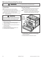
Removing and Replacing Unit ............................... 27
Control Panel Assembly....................................... 27
Control Board Assembly ...................................... 27
Touch Panel ......................................................... 27
Side Trim(s) ......................................................... 27
Stepdown Transformer(s) ..................................... 27
Oven High Limit .................................................... 27
Oven Sensor (some models) ................................ 28
Oven Sensor (some models) ................................ 28
Broil Element / Broil Element Reflector ................ 28
Convection Fan Assembly .................................... 28
Oven Bake Element ............................................. 28
Door Latch / Door Light Switch Assembly ............ 28
Oven Light Assembly ........................................... 29
Oven Door Removal .............................................. 30
Blower Motor ........................................................ 30
Vent Assembly / Smoke Eliminator ..................... 30
Oven Door Hinge .................................................. 30
Frameless Door Disassembly .............................. 30
Microwave Disassembly Procedures
Removing and Replacing Unit ............................... 32
Side Trim(s) ......................................................... 32
Control Panel Assembly ....................................... 32
Control Board Assembly ...................................... 32
Touch Panel ......................................................... 33
Control Power Board ............................................ 33
Filter Assembly Board ......................................... 33
TCO Limit Switches (Oven and Magnetron) .......... 34
Oven Sensor ........................................................ 34
Oven Light Assembly ........................................... 34
Magnetron ............................................................ 35
Transformer .......................................................... 35
Blower Motor ........................................................ 35
Turntable Motor .................................................... 36
Oven Door Removal .............................................. 36
Door Disassembly ................................................ 37
Appendix A
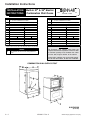
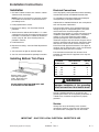
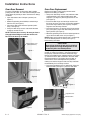
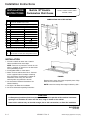
Installation Instructions ....................................... A-2
16022821 Rev. 0
3
Important Safety Information
SELF-CLEANING OVEN
! CAUTION
To avoid personal injury, do not sit, stand or lean on
oven door.
! WARNING
To avoid risk of electrical shock, personal injury, or
death, make sure your oven has been properly
grounded and always disconnect it from main power
supply before any servicing.
1. Do Not Clean Door Gasket—The door gasket is
essential for a good seal. Care should be taken not to
rub, damage, or move the gasket.
2. Do Not Use Oven Cleaners—No commercial oven
cleaner or oven liner protective coating of any kind
should be used in or around any part of the liner.
3. Clean Only Parts Listed in Manual. See Cleaning
section.
4. Before Self-Cleaning the Oven—Remove broiler pan,
oven racks, and other utensils.
OVEN
! CAUTION
This appliance contains or produces a chemical or
chemicals which can cause death or serious illness
and which are known to the state of California to cause
cancer, birth defects or other reproductive harm. To
reduce the risk from substances in the fuel or from fuel
combustion make sure this appliance is installed,
operated, and maintained according to the instructions
in this booklet.
1. Use Care When Opening Door—Let hot air or steam
escape before removing or replacing food.
2. Do Not Heat Unopened Food Containers—Build-up of
pressure may cause container to burst and result in
injury.
3. Keep Oven Vents Ducts Unobstructed.
4. Placement of Oven Racks—Always place oven racks
in desired location while oven is cool. If rack is
removed while oven is hot, do not let potholder contact
hot oven.
In Case of Fire
ALL APPLIANCES
1. Proper Installation—Be sure your appliance is properly
installed and grounded by a qualified technician.
2. Never Use Appliance for Warming or Heating the
Room.
3. Do Not Leave Children Alone—Children should not be
alone or unattended in the area where the appliance is
in use. They should never be allowed to sit or stand on
any part of the appliance.
4. Wear Proper Apparel—Loose fitting or hanging
garments should never be worn while using appliance.
5. User Servicing—Do not repair or replace any part of
the appliance unless specifically recommended in the
manual. All other servicing should be referred to a
qualified technician.
6. Storage in or on Appliance—Flammable materials
should not be stored in oven.
7. Do Not Use Water on Grease Fires—Smother fire or
flame, or use dry chemical or foam-type extinguisher.
8. Use Only Dry Potholders—Moist or damp potholders
on hot surfaces may result in burns from steam. Do
not let potholder touch burners. Do not use a towel or
other bulky cloth.
4
Fires can occur as a result of over cooking or excessive
grease. Though a fire is unlikely, if one occurs, proceed
as follows:
Oven Fires
1. If you see smoke from oven, do not open oven door.
2. Turn oven control to OFF.
3. As an added precaution, turn off power at main circuit
breaker or fuse box.
4. Turn on vent to remove smoke.
5. Allow food or grease to burn itself out in oven.
6. If smoke and fire persist, call fire department.
7. If there is any damage to components, call repair
service before using oven.
Precautions
• Do not mix household cleaning products. Chemical
mixtures may interact with objectionable or even
hazardous results.
• Do not put plastic items on warm cooking areas. They
may stick and melt.
• Do not use damp sponge or dishcloth to clean oven
when oven is hot. Steam from sponge or dishcloth can
burn.
• Do not leave fat heating unless you remain nearby. Fat
can ignite if overheated by spilling onto hot surfaces.
16022821 Rev. 0
©2004 Maytag Appliances Company
Important Safety Information
!
CAUTION
Read the following information to avoid possible
exposure to microwave radiation:
The basic design of the Amana microwave oven makes it
an inherently safe device to both use and service.
However, there are some precautions which should be
followed when servicing the microwave oven to maintain
this safety. These are as follows:
1. Always operate the unit from an adequately grounded
outlet. Do not operate on a two-wire extension cord.
2. Before servicing the unit (if unit is operable) perform
the microwave leakage test.
3. The oven should never be operated if the door does not
fit properly against the seal; the hinges or hinge
bearings are damaged or broken; the choke is
damaged, (pieces missing, etc.); or any other visible
damage can be noted. Check the choke area to
ensure that this area is clean and free of all foreign
matter.
4. If the oven operates with the door open and produces
microwave energy, take the following steps.
A. Tell the user not to operate the oven.
B. Contact Maytag Appliances, Inc.
immediately.
5. Always have the oven disconnected when the outer
case is removed except when making the "live" tests
called for in the Service Manual. Do not reach into the
equipment area while the unit is energized. Make all
connections for the test and check them for tightness
before plugging the cord into the outlet.
6. Always ground the capacitors on the magnetron filter
box and H. V. Capacitor with an insulated-handle
screwdriver before working in the high voltage area of
the equipment compartment. Some types of failures
will leave a charge in these capacitors and the
discharge could cause a reflex action which could
make you injure yourself.
©2004 Maytag Appliances Company
7. In the area of the transformer, capacitor, diode, and
magnetron there is HIGH VOLTAGE. When the unit is
operating - keep this area clean and free of anything
which could possibly cause an arc or ground, etc.
8. Do not for any reason defeat the interlock switches–
there is no valid reason for this action at any time; nor
will it be condoned by Maytag.
9. IMPORTANT: Before returning a microwave to a
customer, check for proper switch interlock action.
The primary and secondary switches MUST open
when the door is actuated. The monitor switch MUST
close at a 1/4 inch when the door is opened.
10. Before returning a microwave to a customer, verify the
door spacing is reasonably uniform along the top,
bottom, and sides and that it measures 1/8 inch or
less.
11. The Maytag microwave oven should never be operated
with:
• Any components removed and/or bypassed.
• Any of the safety interlocks are found to be failed.
• Any of the seal surfaces are defective, missing,
or damaged.
12. To ensure that the unit does not emit excessive
microwave leakage and to meet the Department of
Health Human Service guidelines, check the oven for
microwave leakage using Narda Model 8100, 8200,
Holaday HI1500, HI1501 or Simpson 380M leakage
monitor as outlined in the instructions. The maximum
leakage level allowed is 4mW/cm2.
13. If servicer encounters an emission reading over
4mw/cm2 the servicer is to cease repair and contact
the Amana Service Department immediately for further
direction. Amana Appliances, Inc. will contact the
proper Government Agency upon verification of the test
results.
16022821 Rev. 0
5
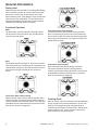
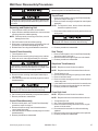
Microwave Leakage Testing
!
Measurement With the Outer Panel
Removed
WARNING
Check for radiation leakage after servicing. Should the
leakage be more than 4mW/cm2 inform Amana
Appliances, Inc. immediately. After repairing or
replacing any radiation safety device, keep a written
record for future reference, as required by DHHS and
HEW regulations. This requirement must be strictly
observed. In addition, the leakage reading must be
recorded on the service repair ticket while in the
customer’s home.
!
DANGER
Avoid contacting any high voltage components.
Whenever you replace the magnetron, measure for
radiation leakage before the outer panel is installed and
after all necessary components are replaced or adjusted.
Special care should be taken in measuring around the
magnetron.
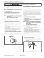
Measurement With a Fully Assembled Oven
Equipment
After all components, including the outer panel are fully
assembled, measure for radiation leakage around the
door periphery, the door viewing window, the exhaust
opening, and air inlet openings.
• Electromagnetic radiation monitor
• 600 cc glass beaker
Procedure For Measuring Radiation
Leakage
Note before measuring • Do not exceed meter full scale deflection. Leak monitor
should initially be set to the highest scale.
• To prevent false readings, the test probe should be held
by the grip portion of the handle only.
• The scan speed is equal to one inch per antenna
revolution or one inch per second if antenna speed is
unknown.
• Areas to be checked are all door seal areas and any
venting parts.
• Leakage with the outer panel removed ...4mW/cm2 or
less.
• Leakage for fully assembled oven with door normally
closed ...4mW/cm2 or less.
• Leakage for a fully assembled oven (before the latch
switch (primary) is interrupted) while pulling the door ...
4mW/cm2 or less.
Record Keeping and Notification After
Measurement
1. After any adjustment or repair to a microwave oven, a
leakage reading must be taken. Record this leakage
reading on the repair ticket even if it is zero.
2. A copy of the repair ticket and the microwave leakage
reading should be kept by the repair facility.
1. Pour 275 ±15 cc (9 oz ±1/2 oz) of 20 ±5°C (68 ±9°F)
water in a beaker which is graduated to 600 cc and
place the beaker in the center of oven.
2. Set the radiation monitor to 2450 MHz and use it
following the manufacturer’s recommended test
procedure to assure correct results.
3. While measuring the leakage, always use the 2–inch
(5 cm) spacer supplied with the probe.
4. Press the start pad or turn on the timer and with the
magnetron oscillating, measure the leakage by
holding the probe perpendicular to the surface being
measured.
6
16022821 Rev. 0
©2004 Maytag Appliances Company
General Information
This manual provides basic instructions and suggestions
for handling, installing , and servicing electric
combination microwave/wallovens.
The directions, information, and warnings in this manual
are developed from experience with, and careful testing
of the product. If the unit is installed according to the
Installation Instructions, it will operate properly and will
require minimal servicing. A unit in proper operating
order ensures the consumer all the benefits provided by
efficient electric cooking.
This manual contains information needed by authorized
service technicians to install and service electric
combination microwave/wallovens pertaining to this
manual. There maybe, however some information which
needs further explanation. Refer to individual Installation
Instructions, Use and Care, Technical Sheets, or toll free
technical support line to answer questions from
authorized service technicians.
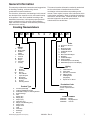
Cooking Nomenclature
J
M
W
8
5
2
7
D
A
W
Color
A
B
C
H
L
P
Q
S
T
W
F
N
Brand
A
C
G
H
J
M
N
U
Y
Amana
Magic Chief
Graffer &
Sattler
Hardwick
Jenn-Air
Maytag
Norge
Universal
Crosley
Listing
Fuel
B
D
E/J
G
L
M
P
X
W
Almond on Almond
Black
Brushed Chrome
Traditional White
Traditional Almond
Prostyle
Monochromatic Bisque
Stainless
Traditional Bisque
White on White
Frost White (True Color White)
Natural Bisque (True Color Bisque)
A
C
D
G
M
P
Butane
Dual Fuel
Electric
Gas, Natural
Liquid Propane
Microwave
Standing Pilot
No Fuel
Warming Drawer
X
UL/AGA
CSA/CGA/CUL
Dual Listed
220-240 V / 50-60 Hz
Military Model
PSB Approved
(Singapore)
Export 120 V / 60 Hz
Production Code
This identifies which
version of production the
unit is.
Product Type
A
C
D
E
G
L
M
P
Q
R
S
T
V
W
Y
Z
Accessory/Cartridge
Cooktop Updraft/Countertop
Downdraft Cooktop or Warming Drawer
Eyelevel Range
Grill
Range (20")
Range (36")
Drop In (24")
Wall Oven (27")
Range, Free-Standing (30")
Slide-In (30")
Range Hood
OTR
Wall Oven
RV Range
RV Top
©2004 Maytag Appliances Company
Feature Content
1000-3999
4000-6999
7000-9999
16022821 Rev. 0
Brands
Maytag/Amana
Jenn-Air
7
General Information
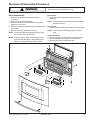
Rating Label
Model numbers are recorded on the rating label. Rating
label is located on under the control panel on the right
hand side. It can be seen by opening the oven door.
Before ordering parts, write down the correct model and
serial number from rating label. This avoids incorrect
shipments and delays. Please refer to parts reference
material when ordering replacement parts.
Functional Operation
Bake
Top and bottom elements operate during bake. Bake
can be used to cook foods which are normally baked.
Oven must be preheated.
Broil
Top element operates during broil. Broil can be used to
cook foods which are normally broiled. Preheating is not
required when using broil. All foods should be turned at
least once except fish, which does not need to be
turned.
Convection Bake (some models)
Upper element, lower element, and fan operate during
convection bake. Convection bake should be used for
cooking casseroles and roasting meats. Oven should be
preheated for best results when using convection bake.
Pans do not need to be staggered.
8
Convection Broil (some models)
Top element and fan operate when using convection
broil. Convection broil can be used to cook foods that
are normally broiled. Oven does not require preheating
when using convection broil. Food does not need to be
turned during cooking.
Convection (some models)
Rear element and fan operate during convection.
Convection should be used for cooking pastries,
souffles, yeast bread, cakes and cookies. Oven should
be preheated for best results when using convection.
Pans do not need to be staggered.
Cooking Guide
Refer to owners manual, for following recommendations
only as a guide for times and temperature. Times, rack
position, and temperatures may vary depending on
conditions and food type. For best results, always check
food at minimum time. When roasting, choose rack
position based on size of food item.
16022821 Rev. 0
©2004 Maytag Appliances Company
General Information
Specifications
Service
Refer to individual Technial Sheet for information
regarding specifications.
Keep a copy of sales receipt for future reference or in
case warranty service is required. To locate an
authorized servicer:
Model Identification
• For Maytag/Jenn-Air product call 1-800-462-9824 or
visit the Web Site at www.maytag.com or
www.jennair.com
• For product inCanada call 1-866-587-2002 or visit the
Web Sites at www.amana.com or www.maytag.com or
www.jennair.com
Warranty service must be performed by an authorized
servicer. We also recommend contacting an authorized
servicer, if service is required after warranty expires.
Complete registration card and promptly return. If
registration card is missing:
• For Maytag product call 1-800-688-9900 or visit the
Web Site at www.maytag.com
• For Jenn-Air product call 1-800-536-6247 or visit the
Web Site at www.jennair.com
• For product in Canada call 1-866-587-2002 or visit the
Web Sites at www.amana.com or www.maytag.com or
www.jennair.com
When contacting provide product information located on
rating plate. Record the following:
Model Number:
Manufacturing Number:
Serial or S/N Number:
Date of purchase:
Dealer’s name and address:
___________________
___________________
___________________
___________________
___________________
Parts and Accessories
Purchase replacement parts and accessories over the
phone. To order accessories for your product call:
• For Maytag/Jenn-Air product call 1-800-462-9824 or
visit the Web Site at www.maytag.com or
www.jennair.com
• For product inCanada call 1-866-587-2002 or visit the
Web Sites at www.amana.com or www.maytag.com or
www.jennair.com
Extended Service Plan
We offer long-term service protection for this new oven.
• Asure™ Extended Service Plan is specially designed
to supplement Amana’s strong warranty. This plan
covers parts, labor, and travel charges.
Call 1-866-232-6244 for information.
• Dependability PlusSM Extended Service Plan is
specially designed to supplement Maytag’s and
Jenn-Air’s strong warranty. This plan covers parts,
labor, and travel charges.
Call 1-800-925-2020 for information.
©2004 Maytag Appliances Company
16022821 Rev. 0
9
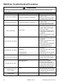
Wall Oven Troubleshooting Procedures
!
WARNING
To avoid risk of electrical shock, personal injury or death: disconnect power to oven before servicing, unless
testing requires it.
Problem
Possible Cause
Open bake element .....................................
No bake element operation
Loose wire connection or broken wire.........
Open broil element ......................................
No broil element operation
Loose wire connection or broken wire.........
Programming error ......................................
Oven not operating
Power outage ..............................................
Power outage ..............................................
Clock and timer not working
Failed oven lamp .........................................
Oven light does not operate
Failed wiring ................................................
Failed light socket........................................
Failed light plunger ......................................
Programming error ......................................
Self-clean cycle not working
Oven is self-cleaning ...................................
Oven is still hot ............................................
Oven door will not unlock
Normal .........................................................
Oven smokes/order first few
times of usage
Failure Codes
10
Electronically Controlled..............................
16022821 Rev. 0
Correction
• Check element for continuity,
replace if failed.
• Verify all connections are clean
and tight, replace broken wire.
• Check element for continuity,
replace if failed.
• Verify all connections are clean
and tight, replace broken wire.
• Shut off power to oven for five
minutes by switching off ciruit
breaker. Reset circuit breaker
and try oven again.
• Verify power is present at unit.
Verify that the circuit breaker is
not tripped.
• Replace household fuse, but do
not fuse capacity.
• Verify power is present at unit.
Verify that the circuit breaker is
not tripped.
• Replace household fuse, but do
not fuse capacity.
• Refer to Use and Care Manual
“Operating Instructions”, if
continues contact service.
• Check lamp and replace is
necessary.
• Check for broken, loose or dirty
connections.
• Check light socket for continuity.
• Check plunger for continuity.
• Shut off power to oven for five
minutes by switching off ciruit
breaker. Reset circuit breaker
and try oven again.
• Allow cycle to complete.
• Will not unlock until unit has
cooled to safe temperature. Do
not force door open, this will void
warranty. Blow cool air on door
latch area to quicken process.
• Minor smoking or order is normal
the first few times of oven usage.
• Ventilate area well and perform
self-clean cycle.
• Refer to specific Technical Sheet
for diagnostic checks.
©2004 Maytag Appliances Company
Microwave Troubleshooting Procedures
!
WARNING
To avoid risk of electrical shock, personal injury or death: disconnect power to oven before servicing, unless
testing requires it.
CAUTIONS
1. Check grounding before checking for trouble.
2. Be careful of the high voltage circuit.
3. Discharge the high voltage capacitor.
4. When checking the continuity of the switches or of the high voltage transformer, disconnect one lead wire
from these parts and then check continuity with the AC plug removed. To do otherwise may result in a
false reading or damage to your meter.
5. Do not touch any part of the circuit on the P.C.B. since static electric discharge may damage this control
panel.
Always touch yourself to ground while working on this panel to discharge any static charge built up in your
body.
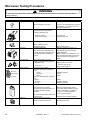
CONDITION
CAUSE
REMEDY
Microwave oven
does not work.
Inserting many plugs into one
outlet and using them at the
same time.
(blown fuse or breaker)
Avoid using other electrical
appliances when you use the
microwave oven.
Microwave oven plug is not
inserted tightly.
Insert microwave oven plug
securely.
Low AC input voltage.
Use the microwave oven at
adequate line voltage.
Food temperature is too low.
This may not be a defect.
It is possible that the food
should be cooked for a
longer time period.
Using metallic ware and
allowing it to touch the oven
wall.
Do not use metallic ware for
cooking except that noted in
the cooking guide.
Ceramic ware trimmed in
gold or silver powder is used.
Do not use any type of
cookware with metallic
trimming.
Inconsistent intensity of
microwave by their
characteristics.
1. Use plastic wrap or lid.
2. Stir once or twice while
cooking soup, cocoa or
milk, etc.
Output power is too low.
Sparks occur.
Uneven cooking.
©2004 Maytag Appliances Company
16022821 Rev. 0
11
Microwave Troubleshooting Procedures
!
WARNING
To avoid risk of electrical shock, personal injury or death: disconnect power to oven before servicing, unless
testing requires it.
CONDITION
1. Fuse blows.
CHECK
Check continuity
of monitor
switch (with
door closed).
RESUL
Continuity.
CAUSE
REMEDY
Malfunction of the
monitor switch.
No continuity.
Replace fuse,
primary, monitor,
P.C.B Assembly.
Replace fuse
Check continuity
of primary switch
and door sensing
switch (with door
opened)
Disconnect one
side of the wire
lead connected
from transformer
to the high voltage
capacitor and
operate the unit.
2. Fuse does
not blow.
Check continuity
of thermostat.
Continuity.
Shorted contact at
the primary switch.
No continuity.
Normal.
Fuse blows again
No continuity.
Replace fuse,
primary, monitor,
P.C.B Assembly.
Failed high
voltage capacitor.
Failed high voltage
transformer.
Replace high
voltage capacitor.
Replace high
voltage
transformer.
Failed
thermostat.
Replace
thermostat.
Failed power
supply cord.
Replace power
supply cord.
Continuity.
Check continuity
of power supply
cord.
12
No continuity.
16022821 Rev. 0
©2004 Maytag Appliances Company
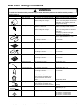
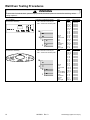
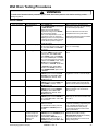
Wall Oven Testing Procedures
!
WARNING
To avoid risk of electrical shock, personal injury or death; disconnect power to oven before servicing, unless
testing requires it.
Illustration
Component
Oven light socket
Oven light housing
Bake element
Test Procedure
Test continuity of receptacle terminals .
Results
Indicates continuity with bulb screwed in.
Measure voltage at oven light ..............
120 VAC; see wiring diagram for terminal
identification. If no voltage is present at
oven light check wiring.
Disconnect connector and test
resistance of terminals .........................
Verify bulb is plugged in properly.
Indicates continuity with bulb installed.
Measure voltage at oven light ..............
12 VAC, see wiring diagram for terminal
identification.
If no voltage is present at oven light,
check wiring or light switches.
2600 W - Approximately 21 Ω - cold
2800 W - Approximately 20 Ω - cold
Test continuity of terminals ..............
Test voltage to terminals..................
240 / 208 VAC
Test continuity of terminals ................
Approximately 20 Ω - cold
Test voltage to terminals....................
240 / 208 VAC
Test continuity of terminals ..............
Approximately 25 Ω - cold
Test voltage to terminals..................
240 / 208 VAC
Test continuity of terminals ................
Approximately 15 Ω - cold
Test voltage to terminals....................
240 / 208 VAC
Resistor assembly
Test continuity of resistor ...................
Approximately 41 Ω
Convection element
Test continuity of terminals ................
Approximately 30 Ω - cold
Test voltage to terminals....................
240 / 208 VAC
Verify supply voltage..........................
120 VAC
Bake element
Broil element
Broil element
Convection motor fan
Check continuity of terminals, and
verify terminals are not shorted to
chassis...............................................
Cooling fan motors
Verify supply voltage..........................
Temperature sensor
Check continuity of terminals, and
verify terminals not shorted to chassis
Measure resistance............................
Controls
Verify proper operation.
Approximately 400 Ω
120 VAC
Continuity
Approximately 1080 Ω at room
temperature (70ºF).
Open at 260°F, Closes at 200°F
Open at 225°F, Closes at 165°F
Open at 215°F, Closes at 155°F
©2004 Maytag Appliances Company
16022821 Rev. 0
13
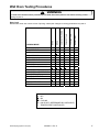
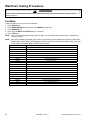
Wall Oven Testing Procedures
!
WARNING
To avoid risk of electrical shock, personal injury or death; disconnect power to oven before servicing, unless
testing requires it.
Illustration
Bottom View
Component
Rotary encoder
Door plunger switch
NC
C
Test Procedure
Test continuity of terminals
Pin 3 to Pin 4 ..................................
Results
No continuity with switch at rest position.
Continuity with switch depressed.
Pin 1 to Pin 4 ..................................
No continuity with switch at rest position.
Continuity with switch depressed and
changes stat as switch is rotated.
Pin 2 to pin 4...................................
No continuity with switch at rest position.
Continuity with switch depressed and
changes stat as switch is rotated.
Remove switch from unit and
measure the following points:
C-NO..................................................
Plunger in continuity, Plunger out infinite.
Switch connection in following
positions:
Unlocked ............................................
COM-NO=Open, COM-NC=Closed
Locked................................................
COM-NO=Closed, COM-NC=Open
Remove switch from unit and
measure the following points:
C-NO..................................................
Plunger in continuity, Plunger out infinite.
Verify input voltage.............................
Verify output voltage...........................
Approximately 120 VAC
Approximately 12 VDC
NO
Motorized door latch
NC
NO
COM
Door switch
NO
COM
Stepdown transformer
Primary
Secondary
14
16022821 Rev. 0
©2004 Maytag Appliances Company
Wall Oven Testing Procedures
!
WARNING
To avoid risk of electrical shock, personal injury or death; disconnect power to oven before servicing, unless
testing requires it.
H1 Control
Illustration
H1 Controlled
Component
Oven temperature
adjustment
H1 Controlled
Temperature display
H1 Controlled
Clock Display
H1 Controlled
24 Hour Clock
H1 Controlled
Factory Default
H1 Controlled
Twelve hour off
H1 Controlled
Sabbath Mode
Test Procedure
Press BAKE pad.
Enter 550 on the digit-pad.
Immediately press and hold BAKE
pad for 3 seconds.
Oven can be adjusted from -35 to +35
degrees in 5-degree increments by
pressing AUTOSET pad. To avoid
over adjusting the oven, move
temperature 5 degrees each time.
Wait 4 seconds for the data entry timer
to expire to accept the change.
Temperature adjustment will be
retained even through a power failure.
Press and hold Cancel and Bake
pads for 3 seconds.
Press and hold Cancel and Clock
pads for 3 seconds.
Press and hold Cancel and Favorite
pads for 3 seconds.
Press and hold Cancel and Keep
Warm pads for 3 seconds.
Control will automatically cancel any
cooking operation and remove all
relay drives 12 hours after the last pad
touch.
Hold CLOCK pad for 3 seconds to
activate Sabbath mode.
Hold CLOCK pad for 3 seconds to
disable Sabbath mode.
H1 Controlled
H1 Controlled
Child lock out
Diagnostic Code
Display
©2004 Maytag Appliances Company
Press and hold Cancel and Cook &
Hold pads for 3 seconds. “OFF” will
display where the temperature
normally appears. “LOCK” will display
flashing while door is locking.
To reactivate the control, press and
hold Cancel and Cook & Hold pads
for 3 seconds.
See “Quick Test Mode”.
Cycle through the codes using the
number pads 1 through 5.
16022821 Rev. 0
Results
While increasing or decreasing oven
temperature, this does not affect selfcleaning temperature.
This mode enables the user to indicate
°F or °C on the display.
Allows clock to be toggled On or OFF.
Allows the time on the clock to be
toggled from 12 hour or 24 hour display.
Allows the clock to be reset to factory
settings.
See Sabbath mode to disable.
“SAb” will be displayed and flash for
5 seconds.
Display will go back to time of day.
All pad inputs are disabled except for
CANCEL and CLOCK pads.
This mode disables the normal 12 hour
shutoff to allow operation of the bake
mode for a maximum of 72 hours.
This is a safety feature that can be used
to prevent children from accidentally
programming the oven. It disables the
electronic oven control.
Child lockout features must be reset after
a power failure.
The last 5 diagnostic codes will be stored
in the non-volatile memory.
See “Description of Error Codes” for
explanation.
15
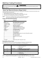
Wall Oven Testing Procedures
!
WARNING
To avoid risk of electrical shock, personal injury or death; disconnect power to oven before servicing, unless
testing requires it.
Jenn-Air Matrix
Control Panel Assembly
Continuity is indicated as follows:
1000 – 6600 Ω for Cancel pad
1000 – 15000 Ω for All other pads
16
9
8
1
Maytag Matrix
Control Panel Assembly
Continuity is indicated as follows:
1000 – 6600 Ω for Cancel pad
1000 – 15000 Ω for All other pads
Delay
CANCEL
Convect
Bake
Bake
Broil
Convect
Roast
Keep
warm
Oven
Light
Clean
Timer
Clock
Cook &
Hold
Favorite
Autoset
16
9
8
1
16
16022821 Rev. 0
Pad
1
2
3
4
5
6
7
8
9
0
Cancel
Clock
Cook & Hold
Broil
Bake
Clean
Keep Warm
Favorite
Timer
Oven Light
Pad
1
2
3
4
5
6
7
8
9
0
Cancel
Clock
Cook & Hold
Broil
Bake
Convect Bake
Convect Roast
Clean
Keep Warm
Favorite
Timer
Oven Light
Trace
13 & 15
12 & 15
10 & 15
7 & 13
12 & 13
10 & 12
4 & 13
4 & 12
5 & 10
5 & 12
1 & 2/3
4 & 14
5 & 14
13 & 14
7 & 15
5&7
14 & 15
5 & 13
4&5
4 & 10
Trace
13 & 15
12 & 13
12 & 15
4 & 11
4 & 12
4 & 10
5 & 11
5 & 13
5 & 10
5 & 12
1&3
7 & 13
11 & 13
11 & 12
10 & 11
11 & 15
5&7
4 & 13
7 & 11
4&5
4&7
10 & 12
Measurement
Continuity
Continuity
Continuity
Continuity
Continuity
Continuity
Continuity
Continuity
Continuity
Continuity
Continuity
Continuity
Continuity
Continuity
Continuity
Continuity
Continuity
Continuity
Continuity
Continuity
Measurement
Continuity
Continuity
Continuity
Continuity
Continuity
Continuity
Continuity
Continuity
Continuity
Continuity
Continuity
Continuity
Continuity
Continuity
Continuity
Continuity
Continuity
Continuity
Continuity
Continuity
Continuity
Continuity
©2004 Maytag Appliances Company
Wall Oven Testing Procedures
!
WARNING
To avoid risk of electrical shock, personal injury or death; disconnect power to oven before servicing, unless
testing requires it.
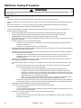
IDLE
BAKE PREHEAT
BAKE
BROIL PREHEAT
BROIL
CLEAN PREHEAT
CLEAN
KEEP WARM
CONVECT BAKE PREHEAT
CONVECT BAKE
CONVECT ROAST PREHEAT
CONVECT ROAST
PROOFING PREHEAT
PROOFING
DRYING PREHEAT
DRYING
r
r
r
r
r
r
r
r
r
r
r
r
OVEN LIGHT
r
r
r
r
r
r
r
r
r
r
r
r
COOLING FAN
r
r
r
r
r
r
CONVECT FAN
r
r
r
CONVECT ELEMENT
COOKING MODE
BROIL
BAKE
Relay Logic
Note that this chart was correct at time of printing; subsequent changes to cooking parameters may alter it.
r
r
KEY INDEX
- OFF
- ON
- CYCLING
- ON OR OFF (DETERMINED BY USER INPUT)
- TEMPERATURE CONTROLLED
©2004 Maytag Appliances Company
16022821 Rev. 0
17
Wall Oven Testing Procedures
!
WARNING
To avoid risk of electrical shock, personal injury or death; disconnect power to oven before servicing, unless
testing requires it.
“Quick Test” Mode for Electronic Range Control
Follow procedure below to use the quick test mode. Entries must be made within 32 seconds of each other or the
control will exit the quick test mode.
1. Press and hold CANCEL and BROIL pads for 3 seconds.
2. Once the control has entered the “Quick Test” mode, release both pads.
3. Press each of the following pads indicated in the table below.
NOTE:
First time one of following pads are pressed it will activate the response.
The second time the pad is pressed it will deactivate the response.
Display will indicate the following:
Pad
Response
BAKE ................................... Bake DLB and Bake relay activated
BROIL.................................. Broil DLB and Broil relay activated
KEEP WARM....................... Bake DLB and Broil DLB activated
CONVECT BAKE ................ Convection Fan on high speed
CONVECT ROAST ............. Cooling Fan activated
CLEAN................................. MDL relay activated
COOK & HOLD ................... Displays last diagnostic code
FAVORITE........................... Displays EEPROM version number
TIMER ................................. Displays main code version number
CLOCK ................................ All display segments illuminated
OVEN LIGHT....................... Oven light activated
CANCEL .............................. Exit Quick Test mode
1........................................... Even segments on
2........................................... Odd segments on
3........................................... Convection Ring activated; Convection Ring DLB activated
4........................................... Bake relay activated
5........................................... Broil relay activated
6........................................... Convection relay activated
7........................................... N/A
8........................................... N/A
9........................................... N/A
AUTOSET............................ Steps through last 5 diagnostic codes
Description of Error Codes
Error diagnostic codes can only be viewed by entering the Diagnostic Code Display Mode.
Each error code is four digits long and is created based on the following table.
Digit
st
1
nd
2
rd
3
th
4
Description
1 – Local to the control circuit board
3 – Sensor or meat probe
4 – Control input
9 – Door lock
Measurable:
d – Diagnostic: measurable parameter
c – Control related, replace control
Secondary System: Sequential numbering
Oven Cavity:
1 – Upper oven (or single cavity oven)
2 – Lower oven
c – Control specific
Primary System:
Diagnostic Code Display Mode can be activated by pressing and holding the AUTOSET pad for 3 seconds at
power-up. Diagnostic Code Display Mode can only be started while powering up the control.
18
16022821 Rev. 0
©2004 Maytag Appliances Company
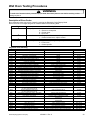
Wall Oven Testing Procedures
!
WARNING
To avoid risk of electrical shock, personal injury or death; disconnect power to oven before servicing, unless
testing requires it.
Diagnostic Code Checking
Code
1c1c
1c2c
1c31
1c32
1c6c
1c7c
1c8c
1d11
1d12
1d21
1d22
3d11
3d12
3d21
3d22
4d11
4d12
4d21
4d31
4d51
4d52
9d11
9d12
9d21
9d22
9d31
9d32
Description
Shorted key
Keyboard tail disconnected
Cancel key circuit problem
Cancel key circuit problem
EEPROM error
Control not calibrated
Cooking program error
Runaway temp (650°F), door unlocked
Runaway temp (650°F), door unlocked
Runaway temp (950°F), door locked
Runaway temp (950°F), door locked
Sensor open
Sensor open
Sensor shorted
Sensor shorted
Door switch position failure
Door switch position failure
No reverse airflow fan rotation (no/low RPM)
Reverse airflow fan state (on when should be off)
Door switch circuit failure
Door switch circuit failure
Latch will not lock
Latch will not lock
Latch will not unlock
Latch will not unlock
Latch state unknown, both locked and unlocked
Latch state unknown, both locked and unlocked
When Checked
Always
Always
Always
Always
When accessing EEPROM
Always
Cook or clean programmed
Latch unlocked
Latch unlocked
Latch locked
Latch locked
Cook or clean active
Cook or clean active
Cook or clean active
Cook or clean active
Clean or keyboard Lockout active
Clean or keyboard Lockout active
Clean or Cook programmed
Suppose to be OFF
Convect, Clean or Keyboard Lockout programmed
Convect, Clean or Keyboard Lockout programmed
Latch should be locked
Latch should be locked
Latch should be unlocked
Latch should be unlocked
Latch should be locked or when lock attempted
Latch should be locked or when lock attempted
Detection
1 minute
1 minute
20 seconds
20 seconds
3 tries
3 tries
3 tries
1 minute
1 minute
1 minute
1 minute
20 seconds
20 seconds
20 seconds
20 seconds
1 minute
1 minute
1 minute
1 minute
1 minute
1 minute
See Note 6
See Note 6
See Note 6
See Note 6
See Note 6
See Note 6
Diagnostic Code Handling
Code
Measurable
What is Displayed
1c1c
Keypress
Nothing
1c2c
Keyboard loop improper value
Nothing
1c31
1c32
1c6c
1c7c
1c8c
1d11
1d12
1d21
1d22
3d11
3d12
3d21
3d22
4d11
4d12
4d21
4d31
4d51
Cancel key improper value
Cancel key improper value
No response from EEPROM
Calibration value out of range
CRC invalid
Sensor resistance > 2237 Ω
Sensor resistance > 2237 Ω
Sensor resistance > 2787 Ω
Sensor resistance > 2787 Ω
Sensor resistance > Infinite Ω
Sensor resistance > Infinite Ω
Sensor resistance > 0 Ω
Sensor resistance > 0 Ω
Door switch not closed when door is locked
Door switch not closed when door is locked
No reverse airflow fan rotation (no/low RPM)
Reverse airflow fan state (on when should be off)
Door switch not open or closed
4d52
Door switch not open or closed
9d11
9d12
9d21
9d22
9d31
9d32
Lock switch not closed
Lock switch not closed
Unlock switch not closed
Unlock switch not closed
Latch both locked and unlocked
Latch both locked and unlocked
©2004 Maytag Appliances Company
BAKE flashes 3
BAKE flashes 3
Nothing
“CAL” in the time digits
Nothing
BAKE flashes 3
BAKE flashes 3
BAKE flashes 3
BAKE flashes 3
BAKE flashes 3
BAKE flashes 3
BAKE flashes 3
BAKE flashes 3
Nothing
Nothing
Nothing
Nothing
Nothing
Nothing
LOCK flashes 3
LOCK flashes 3
LOCK flashes 3
LOCK flashes 3
LOCK flashes 3
LOCK flashes 3
16022821 Rev. 0
Action Taken By Control
Disables audible for affected key depression
Disables all outputs 1, 2
Disables lights and timers
Disables audible for key depression
Disables all outputs 1
Disables lights and timers
Disables all outputs for cavity 1
Disables all outputs for cavity 1
Disables all outputs 1
Completely disables oven 4
Cancels active cook function
Disables all cook function for cavity
Disables all cook function for cavity
Disables all cook function for cavity
Disables all cook function for cavity
Disables all cook function for cavity
Disables all cook function for cavity
Disables all cook function for cavity
Disables all cook function for cavity
Disables Clean and Lockout functions 5
Disables Clean and Lockout functions 5
Disables all cook function for cavity
No action
Disables Convect, Clean, and Lockout functions 4, 5
Turn off light and disable light from door switch
Disables Convect, Clean, and Lockout functions 4, 5
Turn off light and disable light from door switch
Disables Clean and Lockout functions 4
Disables Clean and Lockout functions 4
Disables Clean and Lockout functions 4
Disables Clean and Lockout functions 4
Disables Clean and Lockout functions 4
Disables Clean and Lockout functions 4
19
Wall Oven Testing Procedures
!
WARNING
To avoid risk of electrical shock, personal injury or death; disconnect power to oven before servicing, unless
testing requires it.
NOTES:
1
2
3
4
5
6
“Action Taken” applies as long as the condition exists. If the condition goes away, the control recovers.
If there is a cook function or timer active, the function continues. The user cannot edit the function, and [Cancel] will cancel the cook
mode.
Flash rate: 0.2 seconds on, 0.1 second off. Pressing any key will clear the display until the fault clears and is re-triggered.
“Action Taken” applies until there is a POR (Power On Reset [“hard reset”]).
If the control believes the door is locked, it will attempt to unlock it when the function cancels and the cavity temperature cools.
Special conditions for latch faults (9dxx):
•
A known good unlock position is defined as when the unlock switch reads closed and lock switch reads open.
•
A known good lock position is defined as when the unlock switch reads open and lock switch reads closed.
•
A faulted switch means the switch input is reading an invalid state, neither open nor closed.
•
Once a latch fault occurs, latch movement is disabled until there is a POR. An error tone will sound if a function requiring a
faulted latch is attempted.
•
If at POR, the latch is not at a known good unlock position:
•
If the latch is at a good lock position, it will attempt to unlock when the RTD (Resistance Temperature Device)
temperature is below 400°F.
•
If the latch is not at a good lock position, the control will fault.
•
If a latch fault occurs while the RTD is above the lock temperature, the latch will not try to move, but the fault is still logged
to EEPROM after the first stage of detection.
•
The Display column for latch faults applies 1) If the latch was moving when the fault occurred; 2) If the latch is already in a
known locked state when the fault occurs.
•
•
If the last known good position was unlock (e.g. baking, or idle) and a latch fault occurs, the motor is never moved. The
fault is logged to EEPROM and is not seen by the user.
•
The detection for latch faults is in two stages. The first stage is to let the control recover without moving the latch. After
this:
•
If the latch was previously at a known good unlock position, the latch will not move and the control will fault.
•
If the control was previously in a known good lock position:
•
•
If the RTD is below 400°F, the latch will attempt to recover to it’s proper position (up to three
revolutions). If it cannot, the control will fault and the latch will move to a calculated unlock position.
•
If the RTD is at or above 400°F, the control will fault. When the RTD cools to below 400°F, the control
will attempt to recover to a good unlock position (up to three revolution). If it cannot, the control will fault
and the latch will move to a calculated unlock position.
•
Note: If the unlock position cannot be found, this may result in a second fault, the first fault occurring
when the latch request was locked, and the second when the latch request is unlocked.
If the latch is moving when the fault occurs, the control will bypass the first stage of detection and immediately try
to find it’s proper position. If it cannot, the control will fault and the latch will move to a calculated unlock position.
•
Affected DLBs (Double Line Breaks) and loads are disabled during detection.
•
If the control is in a known good unlock position and the lock switch becomes faulted:
•
20
LOCK flashes after a fault is detected and until the unlocked position is achieved. The unlock position may be
identified by a successful unlock switch closure, or as the result of timing when the unlock switch is not
functioning properly.
•
The control will not fault.
•
If a function requiring latch movement is attempted while the lock switch is faulted, the control will sound an error
tone and the function will be disabled.
If the control is in a known good lock position and the unlock switch becomes faulted:
•
The control will not fault.
•
After the function is canceled and unlock is attempted, the control will attempt to unlock the latch according to the
procedures in these notes.
16022821 Rev. 0
©2004 Maytag Appliances Company
Wall Oven Testing Procedures
!
WARNING
To avoid risk of electrical shock, personal injury or death; disconnect power to oven before servicing, unless
testing requires it.
UH1/2 Control
Illustration
UH1/2 Controlled
Component
Oven temperature
adjustment
UH1/2 Controlled
Temperature display
UH1/2 Controlled
Clock Display
UH1/2 Controlled
12 Hour Shutoff
UH1/2 Controlled
Demo mode
UH1/2 Controlled
Energy Saver
UH1/2 Controlled
208/240 V mode
UH1/2 Controlled
Control Lockout
Test Procedure
Press SETUP pad.
Press DOWN ARROW to scroll down
to TEMP ADJUST.
Select oven and enter desired
temperature change. Press ENTER
pad to accept the change.
Oven can be adjusted from -35 to +35
by pressing +/- pad. To avoid over
adjusting the oven, move temperature
5 degrees each time. Wait 4 seconds
for the data entry timer to expire to
accept the change.
Press SETUP pad and use the arrow
pad to scroll to the next screen. Select
C/F, then select SET. Press SETUP
pad to exit.
Press SETUP pad. Press CLOCK
pad. Press TIME and enter numeric
from key pad. Select AM or PM.
Press SETUP to end. Press SETUP
pad. Press CLOCK pad. Press DAY
pad. Press back forward to select day
of week. Press SETUP to end. Press
SETUP pad. Press CLOCK pad.
Scroll down to 12/24 HR. Scroll down
to 12/24 HR format. Select SET to
activate. Press SETUP pad to exit.
Press DOWN ARROW pad to scroll
to CLOCK.
Press SETUP pad. Press DOWN
ARROW pad to scroll to 12 HOUR
SHUTOFF pad. Select ON or OFF.
Select SET pad to activate. Press
SETUP pad to exit.
Press SETUP pad. Press DOWN
ARROW pad to scroll to DEMO pad.
Select DEMO to activate. Press
SETUP pad to exit.
Press SETUP pad. Press DOWN
ARROW pad to scroll to ENERGY
SAVER pad. Select ON or OFF.
Select SET pad to activate. Press
SETUP pad to exit.
Press SETUP pad. Press DOWN
ARROW pad to scroll to 208/240 V
pad. Select 208 or 240. Select SET
pad to activate.
Press and hold BACK and ENTER
pads for 5 seconds.
To reactivate the control, press and
hold BACK and ENTER pads for 5
seconds.
UH1/2 Controlled
Sabbath Mode
The time of day and
day of week must be
set correctly for this
feature to be
activated.
©2004 Maytag Appliances Company
Press SETUP pad. Press DOWN
ARROW pad. Press SABBATH pad to
activate Sabbath mode.
Select AUTO or MANUAL pad. If
AUTO selected, press continue. If
MANUAL selected, press ON or OFF.
Select SET pad.
16022821 Rev. 0
Results
While increasing or decreasing oven
temperature, this does not affect broiling
or self-cleaning temperature.
The oven offset does not need to be
readjusted if there is a power failure.
Temperature adjustment will be retained
even through a power failure.
This mode enables the user to indicate
°F or °C on the display.
Set clock, day of week, or 12/24 HR
clock.
Allows the time on the clock to be
toggled from 12 hour or 24 hour display.
Control will automatically cancel any
cooking operation and remove all relay
drives 12 hours after the last pad touch.
To save energy, the display will turn off
after five minutes of no use in time of
day mode only.
For improved results when using Radiant
Bake only, the oven can be set from 240
V to 208 V.
This is a safety feature that can be used
to prevent accidentally programming the
oven. It disables the electronic oven
control and locks the cavity door(s).
Control lockout features must be reset
after a power failure.
Auto-Sabbath mode will display a
reminder at 2:00 PM on Friday.
Manual-Sabbath mode will be instantly
programmed for 72 hours.
This mode disables the normal 12 hour
energy saving mode.
21
Wall Oven Testing Procedures
!
WARNING
To avoid risk of electrical shock, personal injury or death; disconnect power to oven before servicing, unless
testing requires it.
Test Mode
Follow procedure below to access the Test Mode.
1. Press SETUP pad.
2. Press DOWN ARROW pad three times until SERVICE is displayed.
3. Press SERVICE pad.
4. Press and hold BACK and ENTER pads for 5 seconds.
5. Press TEST pad.
NOTE: If the oven cavity temperature is greater then 400°F, the Test Mode cannot be activated or will abort the
mode if activated.
NOTE: Once the Test Mode is activated and a function is selected the control will activate the relay until the pad is
pressed again. Upon entering TEST Mode all relays are turned off except the DLB relays, which are turned
on. All relays are turned off when the TEST Mode is exited.
Pad Pressed
22
Relay or Action Activated
Beep
1 Second Beep
Version
Version of software
Last Fault
Display last error code and oven configuration (single, double, convection, nonconvection)
DISP Test
Display segments
UBAKE
Upper Bake Element
UBROIL
Upper Broil Element
UCONV
Upper Convection Element
UCOOL
Upper Cooling Fan
UCONV-H
Upper High Speed Convection Fan
UCONV-L
Upper Low Speed Convection Fan
UMDL
Upper Motorized Door Lock
ULITE
Upper Oven Light
LBAKE
Lower Bake Element
LBROIL
Lower Broil Element
LCONV
Lower Convection Element
LCOOL
Lower Cooling Fan
LCONV-H
Lower High Speed Convection Fan
LCONV-L
Lower Low Speed Convection Fan
LMDL
Lower Motorized Door Lock
LLITE
Lower Oven Light
16022821 Rev. 0
©2004 Maytag Appliances Company
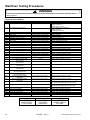
Wall Oven Testing Procedures
!
WARNING
To avoid risk of electrical shock, personal injury or death; disconnect power to oven before servicing, unless
testing requires it.
Description of Error Codes
Error diagnostic codes can only be viewed by entering the Diagnostic Code Display Mode.
Each error code is four digits long and is created based on the following table.
Digit
st
1
nd
2
rd
3
th
4
Description
1 – Local to the control circuit board
3 – Sensor or meat probe
4 – Control input
9 – Door lock
Measurable:
d – Diagnostic failure: measurable parameter
c – Control related error, replace control
Primary failure mechanism
Oven Cavity:
1 – Upper oven (or single cavity oven)
2 – Lower oven
c – Control specific
Primary System:
Diagnostic Code Checking
Code
Description
When Checked
Detection
1c1c
1c2c
1c31
1c32
1c4c
1c6c
1c7c
1c81
1c82
1d11
1d12
1d21
1d22
3d11
3d12
3d21
3d22
3d41
3d51
4d11
4d12
4d21
4d22
4d31
Always
Always
Always
Always
Always
When accessing EEPROM
Always
Cook or clean programmed
Cook or clean programmed
Latch unlocked
Latch unlocked
Latch locked
Latch locked
Cook or Clean active
Cook or Clean active
Cook or Clean active
Cook or Clean active
Probe cook programmed
Always
Clean or Keyboard Lockout active
Clean or Keyboard Lockout active
Cook or Clean programmed
Cook or Clean programmed
When supposed to be off
1 minute
1 minute
20 sec
20 sec
20 sec
3 tries
3 tries
3 tries
3 tries
1 minute
1 minute
1 minute
1 minute
20 sec
20 sec
20 sec
20 sec
20 sec
3 sec
1 minute
1 minute
1 minute
1 minute
1 minute
When supposed to be off
1 minute
4d41
4d42
4d51
Shorted key
Keyboard tail disconnected
Cancel key circuit problem
Cancel key circuit problem
Power micro communication failure
EEPROM error
Control not calibrated
Cook profile corrupted in EEPROM
Cook profile corrupted in EEPROM
Runaway temperature (650°F), door unlocked
Runaway temperature (650°F), door unlocked
Runaway temperature (950°F), door locked
Runaway temperature (950°F), door locked
Temperature sensor failure (open)
Temperature sensor failure (open)
Temperature sensor failure (short)
Temperature sensor failure (short)
Meat probe shorted
Meat probe not calibrated
Door switch position failure
Door switch position failure
No Reverse Airflow Fan rotation (no/low RPM)
No Reverse Airflow Fan rotation (no/low RPM)
Reverse Airflow Fan state error
(on when supposed to be off)
Reverse Airflow Fan state error
(on when supposed to be off)
High Reverse Airflow Fan rotation, high RPM
High Reverse Airflow Fan rotation, high RPM
Door switch circuit failure
1 minute
1 minute
1 minute
4d52
Door switch circuit failure
9d11
9d12
9d21
9d22
9d31
9d32
Latch will not lock 6
Latch will not lock 6
Latch will not unlock 6
Latch will not unlock 6
Latch both locked and unlocked 6
Latch both locked and unlocked 6
Cook or Clean programmed
Cook or Clean programmed
Convect, Clean, or Keyboard Lockout
programmed
Convect, Clean, or Keyboard Lockout
programmed
Latch should be locked
Latch should be locked
Latch should be unlocked
Latch should be unlocked
Latch should be locked or when lock attempted
Latch should be locked or when lock attempted
4d32
©2004 Maytag Appliances Company
16022821 Rev. 0
1 minute
See note 6
See note 6
See note 6
See note 6
See note 6
See note 6
23
Wall Oven Testing Procedures
!
WARNING
To avoid risk of electrical shock, personal injury or death; disconnect power to oven before servicing, unless
testing requires it.
Diagnostic Code Handling
Code
1c1c
Keypress
1c2c
Keyboard loop improper value
1c31
1c32
1c4c
1c6c
1c7c
1c81
1c82
1d11
1d12
1d21
1d22
3d11
3d12
3d21
3d22
3d41
3d51
4d11
4d51
Cancel key improper value
Cancel key improper value
CRC invalid
No response from EEPROM
Calibration value out of range
CRC invalid
CRC invalid
Sensor resistance >2237 Ω
Sensor resistance >2237 Ω
Sensor resistance >2787 Ω
Sensor resistance >2787 Ω
Sensor resistance > Infinite Ω
Sensor resistance > Infinite Ω
Sensor resistance < 0 Ω
Sensor resistance < 0 Ω
Probe resistance < 0 Ω
Calibration value out of range
Door switch not closed when
door is locked
Door switch not closed when
door is locked
Reverse Airflow Fan rotation
(no/low RPM)
Reverse Airflow Fan rotation
(no/low RPM)
Reverse Airflow Fan rotation
(on when should be off)
Reverse Airflow Fan rotation
(on when should be off)
Reverse Airflow Fan rotation
(high RPM)
Reverse Airflow Fan rotation
(high RPM)
Door switch not open or closed
4d52
Door switch not open or closed
mssg 1 (active) / mssg 2 (data)
9d11
9d12
9d21
9d22
9d31
9d32
Lock switch not closed
Lock switch not closed
Unlock switch not closed
Unlock switch not closed
Lock and unlock switches both closed
Lock and unlock switches both closed
mssg 1 (active) / mssg 2 (data)
mssg 1 (active) / mssg 2 (data)
mssg 1 (active) / mssg 2 (data)
mssg 1 (active) / mssg 2 (data)
mssg 1 (active) / mssg 2 (data)
mssg 1 (active) / mssg 2 (data)
4d12
4d21
4d22
4d31
4d32
4d41
4d42
Measured
Display
mssg 1 (active) / mssg 2 (data)
mssg 1 (active) / mssg 2 (data)
mssg 1 (active) / mssg 2 (data)
mssg 1 (active) / mssg 2 (data)
mssg 1 (active) / mssg 2 (data)
mssg 1 (active) / mssg 2 (data)
mssg 1 (active) / mssg 2 (data)
mssg 1 (active) / mssg 3 (data)
mssg 1 (active) / mssg 3 (data)
mssg 1 (active) / mssg 3 (data)
mssg 1 (active) / mssg 3 (data)
mssg 1 (active) / mssg 2 (data)
mssg 1 (active) / mssg 2 (data)
mssg 1 (active) / mssg 2 (data)
mssg 1 (active) / mssg 2 (data)
mssg 1 (active) / mssg 2 (data)
mssg 2
mssg 1
mssg 1
Disable Clean and lockout functions 5
mssg 1 (active) / mssg 2 (data)
Disable all cooking functions for cavity
mssg 1 (active) / mssg 2 (data)
Disable all cooking functions for cavity
No change
No action
No change
No action
mssg 1 (active) / mssg 2 (data)
Disable all cooking functions for cavity
mssg 1 (active) / mssg 2 (data)
Disable all cooking functions for cavity
mssg 1 (active) / mssg 2 (data)
Disable Convect, Clean, and lockout functions 4, 5
Turn off light and disable light from door switch
Disable Convect, Clean, and lockout functions 4, 5
Turn off light and disable light from door switch
Disable Clean and lockout functions 4
Disable Clean and lockout functions 4
Disable Clean and lockout functions 4
Disable Clean and lockout functions 4
Disable Clean and lockout functions 4
Disable Clean and lockout functions 4
Message 1:
FAULT DETECTED
PRESS ENTER
TO TRY AGAIN
24
Action Taken
Disable audible for affected key depression,
Disable all outputs 1, 2
Disable lights and timers
Disable audible for key depression,
Disable all outputs 1
Disable lights and timers
Disable all outputs for cavity 1
Disable all outputs for cavity 1
Disable all outputs 1
Disable all outputs 1
Completely disable oven 4
Disable affected oven function 1
Disable affected oven function 1
Disable all cooking functions for cavity
Disable all cooking functions for cavity
Disable all cooking functions for cavity
Disable all cooking functions for cavity
Disable all cooking functions for cavity
Disable all cooking functions for cavity
Disable all cooking functions for cavity
Disable all cooking functions for cavity
Disable all probe functions
Disable all probe functions
Disable Clean and lockout functions 5
Message 2:
FEATURE NOT
AVAILABLE
PRESS HELP
16022821 Rev. 0
Message 3:
FAULT DETECTED
DISABLE POWER
TO CLEAR
©2004 Maytag Appliances Company
Wall Oven Testing Procedures
!
WARNING
To avoid risk of electrical shock, personal injury or death; disconnect power to oven before servicing, unless
testing requires it.
NOTES:
1
2
3
4
5
6
“Action Taken” applies as long as the condition exists. If the condition goes away, the control recovers.
If there is a cook function or timer active, the function continues. The user cannot edit the function, and [Cancel] will cancel the cook
mode.
Flash rate: 0.2 seconds on, 0.1 second off. Pressing any key will clear the display until the fault clears and is re-triggered.
“Action Taken” applies until there is a POR (Power On Reset [“hard reset”]).
If the control believes the door is locked, it will attempt to unlock it when the function cancels and the cavity temperature cools.
Special conditions for latch faults (9dxx):
•
A known good unlock position is defined as when the unlock switch reads closed and lock switch reads open.
•
A known good lock position is defined as when the unlock switch reads open and lock switch reads closed.
•
A faulted switch means the switch input is reading an invalid state, neither open nor closed.
•
Once a latch fault occurs, latch movement is disabled until there is a POR. An error tone will sound if a function requiring a
faulted latch is attempted.
•
If at POR, the latch is not at a known good unlock position:
•
If the latch is at a good lock position, it will attempt to unlock when the RTD (Resistance Temperature Device)
temperature is below 400°F.
•
If the latch is not at a good lock position, the control will fault.
•
If a latch fault occurs while the RTD is above the lock temperature, the latch will not try to move, but the fault is still logged
to EEPROM after the first stage of detection.
•
The Display column for latch faults applies 1) If the latch was moving when the fault occurred; 2) If the latch is already in a
known locked state when the fault occurs.
•
LOCK flashes after a fault is detected and until the unlocked position is achieved. The unlock position may be
identified by a successful unlock switch closure, or as the result of timing when the unlock switch is not
functioning properly.
•
If the last known good position was unlock (e.g. baking, or idle) and a latch fault occurs, the motor is never moved. The
fault is logged to EEPROM and is not seen by the user.
•
The detection for latch faults is in two stages. The first stage is to let the control recover without moving the latch. After
this:
•
If the latch was previously at a known good unlock position, the latch will not move and the control will fault.
•
If the control was previously in a known good lock position:
•
•
If the RTD is below 400°F, the latch will attempt to recover to it’s proper position (up to three
revolutions). If it cannot, the control will fault and the latch will move to a calculated unlock position.
•
If the RTD is at or above 400°F, the control will fault. When the RTD cools to below 400°F, the control
will attempt to recover to a good unlock position (up to three revolution). If it cannot, the control will fault
and the latch will move to a calculated unlock position.
•
Note: If the unlock position cannot be found, this may result in a second fault, the first fault occurring
when the latch request was locked, and the second when the latch request is unlocked.
If the latch is moving when the fault occurs, the control will bypass the first stage of detection and immediately try
to find it’s proper position. If it cannot, the control will fault and the latch will move to a calculated unlock position.
•
Affected DLBs (Double Line Breaks) and loads are disabled during detection.
•
If the control is in a known good unlock position and the lock switch becomes faulted:
•
•
The control will not fault.
•
If a function requiring latch movement is attempted while the lock switch is faulted, the control will sound an error
tone and the function will be disabled.
If the control is in a known good lock position and the unlock switch becomes faulted:
•
The control will not fault.
•
After the function is canceled and unlock is attempted, the control will attempt to unlock the latch according to the
procedures in these notes.
©2004 Maytag Appliances Company
16022821 Rev. 0
25
Microwave Testing Procedures
!
WARNING
To avoid risk of electrical shock, personal injury or death; disconnect power to oven before servicing, unless
testing requires it.
Illustration
Component
Oven light and socket
Transformer
Test Procedure
Test continuity of receptacle terminals .
Results
Indicates continuity with bulb screwed in.
Measure voltage at oven light...............
120 VAC; see wiring diagram for terminal
identification. If no voltage is present at
oven light check wiring.
Discharge Capacitor
Remove all wires from terminals.
Measure resistance from:
Primary Terminals................................ Less than 1 Ω
Secondary Terminals ........................... Approximately 85 Ω
Turntable
Remove all wires from terminals.
Magnetron
Measure resistance from:
Terminal to terminal................................ Approximately 2238 Ω
Discharge Capacitor
Between Terminals: Less than 1 Ω
Remove wires from magnetron and
connect ohmmeter to terminals. Also
check between each terminal and
ground.
Thermal cutout
Interlock switch
Monitor
Secondary
Primary
Capacitor
Disconnect all wires from TCO.
Measure resistance across terminals.
Magnetron TCO ................................... Open at 230°F (110°C) and
closed at 194°F (90°C)
Cavity TCO .......................................... Opens at 320°F (160°C)
Disconnect wires to switch.
With door open measure resistance
from:
Monitor...........................................
Indicates continuity
Secondary .....................................
Infinite
Primary ..........................................
Infinite
With door closed measure resistance
from:
Monitor.................................................... Infinite
Secondary............................................... Indicates continuity
Primary ................................................... Indicates continuity
Discharge Capacitor
Remove wires from capacitor
terminals and connect ohmmeter, set
on highest resistance scale to
terminals.
Fan Motor
Each terminal to ground measures
Infinite resistance.
Note: This test is not conclusive. If oven
does not heat and all other components
test good replace the magnetron and
retest.
Also check between each terminal and
capacitor case.
Remove all wires from motor.
Between Terminals: Meter should
momentarily deflect towards zero then
return to over 5 MΩ. If no deflection
occurs, or if continuous deflection
occurs, replace capacitor.
Terminal to Case: Infinite resistance
Measure resistance across coil ............... Approximately 63.6 Ω
26
16022821 Rev. 0
©2004 Maytag Appliances Company
Wall Oven Disassembly Procedures
To avoid risk of electrical shock, personal injury or death;
disconnect power to unit before servicing.
Touch Panel
To avoid risk of personal injury or property damage this
unit requires a two person lift when lifting unit in or out
of cutout.
1. Remove control panel, see “Control Panel Assembly”
procedure, steps 1 through 3.
2. Remove screws securing touch panel to control panel
assembly.
NOTE: Touch panel is loose, but the ribbon cable does
not allow complete removal.
Removing and Replacing Unit
1. Turn off power to the oven at the circuit breaker.
2. Open oven door and Microwave door to remove screws
securing unit to the cabinet opening.
3. Disconnect ribbon cable from touch panel and remove
touch panel.
NOTE: Place a protective covering on the floor, to avoid
damage to the floor.
While unplugging electrical connections, pins may be
damaged, use extreme care when disconnecting.
3. Pull unit forward out of the cabinet opening.
4. Disconnect or unplug the power cord leading from unit
to fuse box or junction box depending on unit.
5. Reinstall the oven using the installation instructions.
4. Reverse procedure to reassemble.
Control Panel Assembly
Side Trim(s)
1. Turn off power to unit.
2. Remove screws securing trim piece(s) to the cabinet.
3. Slide unit out of cutout approximately 6 to 8 inches.
To avoid risk of property damage and personal injury,
place blocking material undernieth the front edge of the
wall oven to prevent unit from tipping forward.
4. Remove screws securing control panel assembly to
unit chassis.
5. Label and disconnect wire terminal plugs from control
board assembly.
While unplugging electrical connections, pins may be
damaged, use extreme care when disconnecting.
1. Remove control panel, see “Control Panel Assembly”
procedure, steps 1 through 3.
2. Remove screws securing trim piece to unit chassis.
3. Reverse procedure to reassemble.
Stepdown Transformer(s)
NOTE: Requires removal of unit from cabinet.
NOTE: Requires removal of microwave from wall oven.
1.
2.
3.
4.
Turn off power to unit.
Remove screws securing trim piece(s) to the cabinet.
Remove unit from cutout.
Remove screws securing top cover to outer shell and
remove top cover.
5. Label and disconnect wire terminals from transformer.
6. Remove screws securing transformer to control box.
7. Reverse procedure to reassemble.
Oven High Limit
6. Place control panel assembly on a protected surface.
7. Reverse procedure to reassemble.
NOTE: Requires removal of unit from cabinet.
Control Board Assembly
1. Turn power off to unit.
2. See “Control Panel Assembly” for removal.
3. Remove screws securing rear access cover, to gain
access to limits switch.
4. Disconnect wire terminals from limit switch being
replaced.
5. Remove screws securing limit switch to be replaced.
6. Reverse procedure to reassemble.
1. Remove control panel, see “Control Panel Assembly”
procedure, steps 1 through 6.
2. Remove screws securing control board bracket to
control panel assembly.
3. Label and disconnect ribbon terminal plug from control
board assembly.
4. Reverse procedures to reassemble.
©2004 Maytag Appliances Company
NOTE: Requires removal of microwave from wall oven.
16022821 Rev. 0
27
Wall Oven Disassembly Procedures
To avoid risk of electrical shock, personal injury or death;
disconnect power to unit before servicing.
Oven Sensor (some models)
Convection Fan Assembly
1. Turn off power to unit
2. Open oven door or remove oven door, see “Door
Removal”.
3. Remove screws securing sensor to center portion of
broiler element in the rear of the oven cavity.
1. Turn off power to unit.
2. Open oven door or remove oven door, see “Door
Removal”.
3. Remove screws securing convection fan cover to
convection fan assembly.
4. Remove screws securing convection fan assembly to
rear of oven cavity.
5. Slide convection fan assembly down and tilt forward on
the top portion to allow assembly to pass through rear
oven cavity.
6. Disconnect and label wires from convection fan motor.
7. Reverse procedure to reassemble convection fan
assembly.
NOTE: Gently pull wiring through cavity wall.
4. Pull sensor forward, manuver wires through insulation
and broiler element bracket to disconnect wire plug
connector.
5. Reverse procedure to reassemble sensor.
Oven Sensor (some models)
1. Disconnect power before servicing.
2. Open oven door or remove oven door, see “Door
Removal”.
3. Remove screws securing sensor to oven cavity.
NOTE: Gently pull wiring through cavity wall.
4. Disconnect oven sensor at the connector block and
remove.
5. Reverse procedure to reassemble sensor.
NOTE: Verify connection is pushed through the
insulation.
Broil Element / Broil Element Reflector
1. Turn off power to unit.
2. Open oven door or remove oven door, see “Door
Removal”.
3. Remove screws securing broil element to top and rear
of oven cavity.
4. Allow front of broil element to drop down, then pull
forward to allow terminals to pass through oven cavity.
5. Disconnect wire terminals form element and sensor
wire plug connector.
6. Remove screws securing oven sensor to broil element.
7. Reverse procedure to reassemble broil element.
28
Oven Bake Element
NOTE: Requires removal of unit from cabinet.
1. Turn off power to unit.
2. Open oven door or remove oven door, see “Door
Removal”.
3. Remove screws securing trim piece(s) to the cabinet.
4. Remove unit from cutout, see “Removing and
Replacing Unit” procedure.
5. Disconnect or unplug the power cord leading from unit
to fuse box or junction box depending on unit.
6. Remove screws securing rear top and bottom access
panel.
7. Gently pull plastic wire clips from oven chassis
securing wire harness.
8. Remove screws securing element panel to oven
chassis.
9. Remove screws securing element support bracket.
10. Gently pull element and support bracket from oven
chassis.
11. Reverse procedure to reassemble bake element.
Door Latch / Door Light Switch Assembly
1. Turn off power to unit.
2. Remove top oven door, see “Oven Door” procedure.
3. Remove screws securing middle trim piece between
oven doors.
4. Remove screws securing latch assembly or door light
switch to trim piece.
5. Disconnect and label wire terminals.
6. Remove latch assembly or door light switch from
chassis.
7. Reverse procedure to reassemble door latch assembly
or door light switch.
16022821 Rev. 0
©2004 Maytag Appliances Company
Wall Oven Disassembly Procedures
To avoid risk of electrical shock, personal injury or death;
disconnect power to unit before servicing.
Oven Light Assembly
Oven Light Bulb/Oven Light Socket (some models)
Oven Light Bulb/Oven Light Socket (some models)
NOTE: Requires removal of unit from cabinet to replace
oven light socket.
NOTE: Requires removal of unit from cabinet to replace
oven light socket.
1.
2.
3.
4.
Turn off power to unit.
Open oven door to gain access to oven light.
Unscrew (counterclockwise) glass knurled dome.
Unscrew (counterclockwise) oven light bulb.
NOTE: To avoid damaging the new bulb and decreasing
life of the bulb, do not touch new bulb with bare
hands or fingers.
Hold with a cloth or paper towel.
NOTE: Proceed with the following steps for oven light
socket removal.
5. Remove unit from cutout, see “Removing and
Replacing Unit” procedure.
6. Disconnect or unplug the power cord leading from unit
to fuse box or junction box depending on unit.
7. Remove screws securing outer wrapper back cover
and remove.
8. Carefully displace fiberglass insulation away from rear
of light socket.
9. Push inner assembly of light socket towards rear of
range, or twist out, depending on style of base.
10. Disconnect wires from light socket.
11. Reverse procedure to reinstall light socket. Reposition
insulation around lamp socket. Do not overtighten.
NOTE: Reposition fiberglass insulation around oven light
socket to eliminate possibility of heat related
problems.
The oven light used on the wall oven is a 12 volt 10 Watt
Halogen bulb. The light automatically comes on when the
door is opened or activation may occur via the light pad
when the door is closed. The light will not operate during
a clean cycle. The oven light will automatically come on
one minute before the end of a clock controlled cooking
operation.
1. Disconnect power before servicing.
2. Open oven door and locate oven light.
3. Grasp lens cover and pull outward on one side to gain
access to bulb.
4. Carefully remove old bulb, by lifting bulb straight out of
ceramic base.
NOTE: To avoid damaging the new bulb and decreasing
life of the bulb, do not touch new bulb with bare
hands or fingers.
Hold with a cloth or paper towel.
NOTE: Proceed with the following steps for oven light
socket removal.
5. Remove unit from cutout, see “Removing and
Replacing Unit” procedure.
6. Disconnect or unplug the power cord leading from unit
to fuse box or junction box depending on unit.
7. Remove screws securing side wrapper and remove.
8. Carefully displace fiberglass insulation away from rear
of light socket.
9. Release metal tabs on light socket and push socket
assembly away from the oven cavity.
10. Disconnect wires from light socket.
11. Reverse procedure to reinstall light socket. Reposition
insulation around lamp socket.
NOTE: Reposition fiberglass insulation around oven light
socket to eliminate possibility of heat related
problems.
Bulb
Socket
Lens
Bulb specifications
G4 Type Halogen Bi-Pin 10 w -12V
©2004 Maytag Appliances Company
16022821 Rev. 0
29
Wall Oven Disassembly Procedures
To avoid risk of electrical shock, personal injury or death;
disconnect power to unit before servicing.
Oven Door Removal
Frameless Door Disassembly
1. Open oven door and place door hinge locking device in
lock postion.
2. Place oven door in first stop position, then grasp both
sides and lift up off the hinges.
3. Reverse procedure to reassemble oven door.
1. Remove oven door, see "Oven Door Removal"
procedure.
2. Place door on a protected surface.
3. Remove screws securing bottom trim to oven door.
4. Slide outer oven door glass and trim towards the
bottom of the oven door and remove.
5. Detach right and left trim pieces for outer door glass.
Blower Motor
NOTE: Proceed with the following steps for door hinge,
door handle, and inner door disassembly.
NOTE: Requires removal of unit from cabinet.
1. Remove unit from cutout, see “Removing and
Replacing Unit” procedure.
2. Remove screws securing top access panel.
3. Disconnect and label wire terminals from blower motor.
4. Remove screws securing blower assembly to oven
chassis.
5. Reverse procedure to reassemble blower motor.
Vent Assembly/Smoke Eliminator
1. Turn power off to unit.
2. Open oven door and remove screws securing unit to
the wall.
3. Remove oven from cutout opening.
4. Disconnect or unplug the power cord leading from unit
to fuse box or junction box depending on unit.
5. Remove screws securing top and back outer wrapper
from the unit.
6. Remove screws securing vent assembly to outer
cabinet top wrapper.
7. Raise back of vent assembly and slowly maneuver
vent assembly away from unit.
8. Remove screws securing smoke eliminator, located
inside oven on top of oven cavity.
9. Reverse procedure to reinstall.
Oven Door Hinge
6. Remove screws securing door hinge to oven door
chassis.
NOTE: Proceed with the following steps for door handle
and inner door disassembly.
7. Remove screws securing top door handle trim to oven
door chassis.
8. Remove screws securing door handle brackets to
inner door panel.
9. Lift upward on the lower side of the door handle to
release side alignment screws and rotate towards the
top of the oven door to release and remove.
10. Remove screws securing door handle to door handle
brackets.
NOTE: Proceed with the following steps for inner door
disassembly.
11. Remove screws securing lower door glass retainer to
door baffle and remove.
12. Slide inner door glass downward to release from upper
door glass retainers and remove.
13. Remove screws securing door baffle to door lining and
remove.
14.Remove insulation from oven door.
15. Lift inner glass and glass frame from oven door.
16. Reverse procedure to reassemble oven door.
1. Turn off power to unit.
2. Remove oven door, see “Door Removal”.
3. Remove control panel, see “Control Panel Assembly”
procedure, steps 1 through 3.
4. Remove the top and bottom screws securing hinge
assembly to the front frame.
5. Remove hinge from oven chassis.
6. Reverse procedure to reassemble oven door hinge.
30
16022821 Rev. 0
©2004 Maytag Appliances Company
Wall Oven Disassembly Procedures
To avoid risk of electrical shock, personal injury or death;
disconnect power to unit before servicing.
Frameless Door
Oven door
gasket
Door
insulation
retainer
Door linner
shield
Window
frame
Glass
window
Door face
assembly
Door
linner
Glass window
double coated
Oven door
insulation
Door
handle
Insulation
Bottom shield
Door Assembly
©2004 Maytag Appliances Company
16022821 Rev. 0
31
Microwave Disassembly Procedures
!
To avoid risk of electrical shock, personal injury or death;
disconnect power to unit before servicing.
WARNING
Control Panel Assembly
! CAUTION
NOTE: Requires removal of unit from cabinet.
To avoid risk of personal injury or property damage this
unit requires a two person lift when lifting unit in or out
of cutout.
Removing and Replacing Unit
1. Turn off power to the unit at the circuit breaker.
2. Open oven door and microwave door to remove screws
securing unit to the cabinet opening.
NOTE: Place a protective covering on the floor, to avoid
damage to the floor.
! CAUTION
1. Turn off power to the unit at the circuit breaker.
2. Open oven door and microwave door to remove screws
securing trim of unit to the cabinet opening.
NOTE: Place a protective covering on the floor, to avoid
damage to the floor.
! CAUTION
To avoid risk of property damage and personal injury,
place blocking material underneath the front edge of
the wall oven to prevent unit from tipping forward.
To avoid risk of property damage and personal injury,
place blocking material underneath the front edge of
the wall oven to prevent unit from tipping forward.
3. Slide unit out of cutout.
4. Remove screws securing top wrapper to chassis and
remove top cover.
5. Disconnect wire terminal plug from power control
board.
3. Pull unit forward out of the cabinet opening.
4. Disconnect or unplug the power cord leading from unit
to fuse box or junction box depending on unit.
5. Reinstall the oven using the installation instructions.
! CAUTION
Side Trim(s)
NOTE: Requires partial removal of unit from cabinet.
1. Remove screws securing trim piece(s) to the cabinet.
2. Slide unit out of cutout approximately 6 to 8 inches.
! CAUTION
To avoid risk of property damage and personal injury,
place blocking material underneath the front edge of
the wall oven to prevent unit from tipping forward.
3. Remove screws securing trim piece to unit chassis.
4. Reverse procedure to reassemble.
32
While unplugging electrical connections, pins may be
damaged, use extreme care when disconnecting.
6. Lift upward on control panel assembly and tilt top
portion of assembly towards the front of unit to release
plastic tabs securing assembly.
7. Place control panel assembly on a protected surface.
8. Reverse procedure to reassemble.
Control Board Assembly
NOTE: Requires removal of unit from cabinet.
1. Remove control panel, see “Control Panel Assembly”
procedure, steps 1 through 7.
2. Disconnect terminal plug from control panel.
3. Slide control board holder to the left to release from
control panel.
4. Release both plastic tabs securing control board to
holder and tilt top portion of control board outward to
remove.
5. Reverse procedures to reassemble.
16022821 Rev. 0
©2004 Maytag Appliances Company
Microwave Disassembly Procedures
!
To avoid risk of electrical shock, personal injury or death;
disconnect power to unit before servicing.
WARNING
Touch Panel
NOTE: Requires removal of unit from cabinet.
1. Turn off power to the unit at the circuit breaker.
2. Open oven door and microwave door to remove screws
securing trim of unit to the cabinet opening.
4. Remove screws securing top wrapper to chassis and
remove top cover.
5. Label and disconnect wire terminals from control
power board.
! CAUTION
NOTE: Place a protective covering on the floor, to avoid
damage to the floor.
While unplugging electrical connections, pins may be
damaged, use extreme care when disconnecting.
! CAUTION
6. Remove screws securing transformer to power control
board bracket.
7. Reverse procedure to reassemble.
To avoid risk of property damage and personal injury,
place blocking material underneath the front edge of
the wall oven to prevent unit from tipping forward.
3. Slide unit out of cutout.
4. Remove screws securing top wrapper to chassis and
remove top cover.
5. Disconnect terminal plug from control panel.
Filter Assembly Board
NOTE: Requires removal of unit from cabinet.
1. Turn off power to the unit at the circuit breaker.
2. Open oven door and microwave door to remove screws
securing trim of unit to the cabinet opening.
NOTE: Place a protective covering on the floor, to avoid
damage to the floor.
! CAUTION
While unplugging electrical connections, pins may be
damaged, use extreme care when disconnecting.
6. Slide control board holder to the left to release from
control panel.
7. Reverse procedure to reassemble.
Control Power Board
NOTE: Requires removal of unit from cabinet.
1. Turn off power to the unit at the circuit breaker.
2. Open oven door and microwave door to remove screws
securing trim of unit to the cabinet opening.
NOTE: Place a protective covering on the floor, to avoid
damage to the floor.
! CAUTION
To avoid risk of property damage and personal injury,
place blocking material underneath the front edge of
the wall oven to prevent unit from tipping forward.
3. Slide unit out of cutout.
4. Remove screws securing top wrapper to chassis and
remove top cover.
5. Label and disconnect wire terminals from filter
assembly board.
6. Remove screws securing filter assembly board to
blower bracket.
7. Reverse procedure to reassemble.
! CAUTION
To avoid risk of property damage and personal injury,
place blocking material underneath the front edge of
the wall oven to prevent unit from tipping forward.
3. Slide unit out of cutout.
©2004 Maytag Appliances Company
16022821 Rev. 0
33
Microwave Disassembly Procedures
!
To avoid risk of electrical shock, personal injury or death;
disconnect power to unit before servicing.
WARNING
TCO Limit Switches (Oven and Magnetron)
! CAUTION
NOTE: Requires removal of unit from cabinet.
1. Turn off power to the unit at the circuit breaker.
2. Open oven door and microwave door to remove screws
securing trim of unit to the cabinet opening.
NOTE: Place a protective covering on the floor, to avoid
damage to the floor.
! CAUTION
To avoid risk of property damage and personal injury,
place blocking material underneath the front edge of
the wall oven to prevent unit from tipping forward.
3. Slide unit out of cutout.
4. Remove screws securing top to chassis and remove
top cover.
Magnetron TCO
5. Disconnect wire terminals from magnetron TCO
switch.
6. Remove screw securing TCO to magnetron.
To avoid risk of property damage and personal injury,
place blocking material underneath the front edge of
the wall oven to prevent unit from tipping forward.
3. Slide unit out of cutout.
4. Remove screws securing top wrapper to chassis and
remove top cover.
5. Remove screws securing sensor to center portion of
the oven cavity.
6. Disconnect wire terminal plug connector from power
control board.
7. Reverse procedure to reassemble sensor.
Oven Light Assembly
NOTE: Requires removal of unit from cabinet to replace
oven light or light socket.
1. Turn off power to the unit at the circuit breaker.
2. Open oven door and microwave door to remove screws
securing trim of unit to the cabinet opening.
Oven TCO
7. Remove screws securing right side wrapper and
sliding right side wrapper towards the back of the unit.
NOTE: Place a protective covering on the floor, to avoid
damage to the floor.
NOTE: To release front edge of side wrapper, slightly pry
support bracket away from side wrapper, while
sliding panel towards the back of unit.
! CAUTION
8. Disconnect wire terminals from limit switch.
9. Remove screw securing light socket to side air vent.
10. Remove light assembly from mounting area.
11. Remove screws securing barrier bracket to side air
vent and remove.
12. Remove screw securing side air vent to magnetron.
13. Pull outward on the bottom of the side air vent to allow
limit switch to be removed.
14. Reverse procedure to reassemble.
To avoid risk of property damage and personal injury,
place blocking material underneath the front edge of
the wall oven to prevent unit from tipping forward.
3. Slide unit out of cutout.
4. Remove screws securing top wrapper to chassis and
remove top cover.
5. Remove screws securing light socket to side air vent.
6. Replace oven light.
7. Disconnect wire terminals from light socket, if socket
needs replaced.
8. Reverse procedure to reassemble.
Oven Sensor
NOTE: Requires removal of unit from cabinet.
1. Turn off power to the unit at the circuit breaker.
2. Open oven door and microwave door to remove screws
securing trim of unit to the cabinet opening.
NOTE: Place a protective covering on the floor, to avoid
damage to the floor.
34
16022821 Rev. 0
©2004 Maytag Appliances Company
Microwave Disassembly Procedures
!
To avoid risk of electrical shock, personal injury or death;
disconnect power to unit before servicing.
WARNING
Magnetron
4. Remove screws securing top and right side wrapper to
chassis and remove top cover.
5. Slide right side wrapper towards the back of the unit.
NOTE: Requires removal of unit from cabinet.
1. Turn off power to the unit at the circuit breaker.
2. Open oven door and microwave door to remove screws
securing trim of unit to the cabinet opening.
NOTE: Place a protective covering on the floor, to avoid
damage to the floor.
NOTE: To release front edge of side wrapper, slightly pry
support bracket away from side wrapper.
6. Disconnect wire terminals from transformer.
NOTE: Removal of magnetron maybe required to gain
better access to transformer screws.
7. Remove screws securing transformer to chassis.
8. Reverse procedure to reassemble.
! CAUTION
To avoid risk of property damage and personal injury,
place blocking material underneath the front edge of
the wall oven to prevent unit from tipping forward.
Blower Motor
NOTE: Requires removal of unit from cabinet.
3. Slide unit out of cutout.
4. Remove screws securing top and right side wrapper to
chassis and remove top cover.
5. Slide right side wrapper towards the back of the unit.
NOTE: To release front edge of side wrapper, slightly pry
support bracket away from side wrapper, while
sliding panel towards the back of unit.
6. Disconnect wire terminals from magnetron.
7. Remove screw securing side air vent to magnetron.
8. Remove screws securing magnetron to waveguide
bracket.
NOTE: When replacing magnetron, verify magnetron
gasket is in good condition and correctly
positioned.
1. Turn off power to the unit at the circuit breaker.
2. Open oven door and microwave door to remove screws
securing trim of unit to the cabinet opening.
NOTE: Place a protective covering on the floor, to avoid
damage to the floor.
! CAUTION
To avoid risk of property damage and personal injury,
place blocking material underneath the front edge of
the wall oven to prevent unit from tipping forward.
9. Reverse procedure to reassemble.
3. Slide unit out of cutout.
4. Remove screws securing top and right side wrapper to
chassis and remove top cover.
5. Slide right side wrapper towards the back of the unit.
Transformer
NOTE: To release front edge of side wrapper, slightly pry
support bracket away from side wrapper, while
sliding panel towards the back of unit.
NOTE: Requires removal of unit from cabinet.
1. Turn off power to the unit at the circuit breaker.
2. Open oven door and microwave door to remove screws
securing trim of unit to the cabinet opening.
NOTE: Place a protective covering on the floor, to avoid
damage to the floor.
! CAUTION
To avoid risk of property damage and personal injury,
place blocking material underneath the front edge of
the wall oven to prevent unit from tipping forward.
6. Disconnect wire terminals from blower motor.
7. Remove screws securing blower motor bracket to the
back panel.
8. Remove screw securing diode terminal to ground
terminal.
9. Carefully maneuver the blower motor bracket out of the
oven chassis.
10. Disconnect wire terminals from blower motor.
11. Remove screws securing blower motor to blower motor
bracket.
12. Reverse procedure to reassemble.
3. Slide unit out of cutout.
©2004 Maytag Appliances Company
16022821 Rev. 0
35
Microwave Disassembly Procedures
!
To avoid risk of electrical shock, personal injury or death;
disconnect power to unit before servicing.
WARNING
Turntable Motor
Oven Door Removal
NOTE: Requires removal of unit from cabinet.
1. Open oven door and place door hinge locking device
into the hinge hole of both sides of the oven door.
1. Turn off power to the unit at the circuit breaker.
2. Open oven door and microwave door to remove screws
securing trim of unit to the cabinet opening.
NOTE: Place a protective covering on the floor, to avoid
damage to the floor.
! CAUTION
To avoid risk of property damage and personal injury,
place blocking material underneath the front edge of
the wall oven to prevent unit from tipping forward.
NOTE: You will have to custom fabricate two hinge
locking device, which needs to be approximately
1/4" thick, 5/8" wide, and at least 1-1/2" long.
Door
Hinge
Locking
Devices
3. Slide unit out of cutout.
4. Remove screws securing microwave to the wall oven
(front trim bracket, back, left and right sides).
5. Tip unit on it’s back.
6. Remove screw securing access panel to bottom of
microwave cabinet.
7. Remove access panel.
8. Disconnect wire terminals from turntable motor.
9. Reverse procedure to reassemble.
2. While grasping both sides of the oven door, raise the
oven door upward, to release the oven door hinges
from the oven chassis.
3. Reverse procedure to reassemble oven door.
36
16022821 Rev. 0
©2004 Maytag Appliances Company
Microwave Disassembly Procedures
!
To avoid risk of electrical shock, personal injury or death;
disconnect power to unit before servicing.
WARNING
Door Disassembly
1. Remove oven door, see “Oven Door Removal”
procedure.
2. Place door on a protected surface.
3. Remove screws (course threaded) securing bottom
glass trim to oven door.
4. Remove screws (fine threaded) securing top glass trim
to oven door.
5. Remove outer door glass from inner door.
NOTE: Proceed with the following steps for door hinge,
door handle, and interlock latch.
NOTE: If replacing door hinges, remove hinge locking
devices from both hinges. If not replacing door
hinges, leave hinge locking devices in place.
Door Hinges
6. Remove screws securing door hinge to inner door
assembly.
NOTE: Proceed with the following steps for door handle
and interlock latch.
Door Handle
7. Remove nuts securing door handle to outer door glass.
NOTE: Proceed with the following steps for interlock
latch.
Interlock Latches
8. Remove spring from latch bracket to release tension.
9. Remove latch pin securing latch to latch bracket.
10. Reverse procedure to reassemble door.
\\
©2004 Maytag Appliances Company
16022821 Rev. 0
37
Microwave Disassembly Procedures
!
WARNING
To avoid risk of electrical shock, personal injury or death;
disconnect power to unit before servicing.
This page intentionally left
blank.
38
16022821 Rev. 0
©2004 Maytag Appliances Company
Appendix A
©2004 Maytag Appliances Company
16022821 Rev. 0
A–1
Installation Instructions
fkpq^ii^qflk
fkpqor`qflkp
_Jf OT²² C PM²² b
`~ t~ l
OT² t^ii lsbk abp`ofmqflk
1
2
403 WEST FOURTH STREET, NORTH
NEWTON, IA 50208
PM² t^ii lsbk abp`ofmqflk
1-1/4² Dia. Conduit Access Hole*
5/8² Plywood Floor (Must Support 275 lbs.)
1
2
1-1/4² Dia. Conduit Access Hole*
5/8² Plywood Floor (Must Support 275 lbs.)
afjbkpflkp
A
B
C
D
E
F
G
H
I
27 MIN
24 MIN
51-7/8 + 1/16
24 MIN
25-1/2 + 1/16
52-15/16
26-3/4
25-7/16
4 to 10
afjbkpflkp
68.58 MIN
60.96 MIN
131.76 + .16
60.96 MIN
64.77 + .16
134.46
67.95
64.61
10.2 to 25.4
A
B
C
D
E
F
G
H
I
30 MIN
24 MIN
51-7/8 + 1/16
24 MIN
28-1/2 + 1/16
52-15/16
29-3/4
25-7/16
4 to 10
76.20 MIN
60.96 MIN
131.76 + .16
60.96 MIN
72.39 + .16
134.46
75.57
64.61
10.2 to 25.4
* Hole must be cut as close to corner of cabinet as possible.
`^rqflk
klqbp
For European style cabinets (flush front) the
required clearance for operation of the oven door
is minimum spacing of 7/8² between the cutout
and the door, hinge or drawer of the cabinet.
Z
Do not block air exhaust slots along bottom of
oven.
Some built-in cabinets may not be wide enough,
due to their construction, to allow this installation.
`lj_fk^qflk t^iilsbk `rqlrq
UNMNmQUPJSM
(05-03-00)
A–2
16022821 Rev. 0
©2004 Maytag Appliances Company
Installation Instructions
f~~
b~ `
1. Cut hole in cabinet to mount oven. Cutout in cabinet
should be level and straight.
Unit to be properly circuit protected and wired according
to local electrical code and National Electrical Code.
klqbW There are no provisions to level the unit after
it is installed. An oven that is not level could cause
poor baking results.
It is advisable that the electrical wiring and hookup be
accomplished by a competent electrician.
120/240 VAC or 120/208 VAC 60 Hz. See serial plate on
each unit for power requirements.
2. Install plywood floor as shown.
3. Remove oven door(s). See Oven Door Removal
procedure.
The neutral of the lower unit is grounded to the frame
through the green or solid grounding wire. (The green
and the white wires are twisted together at the
termination of the conduit.) If used on new branch-circuit
installations (1996 NEC), mobile homes, recreational
vehicles, or in an area where local codes prohibit
grounding through the neutral conductor, untwist or
disconnect the green wire and connect the green wire to
ground in accordance with local code. Connect the white
neutral to the service neutral. Connect all wires to the
branch circuit with approved connectors. Use copper or
aluminum wire. If aluminum wire is used, use connectors
recognized for joining aluminum to copper.
4. Attach unit to the cabinet with four No. 8 x 1² screws
supplied with unit inside of envelope containing these
instructions. Pre-drill holes in cabinet for attachment
screws using 1/8² drill. Oven mounting holes are
provided in side trim.
5. Install bottom trim.
6. Replace oven door(s). See Oven Door Replacement
procedure.
7. See instructions at right for electrical hook-up.
The chart below recommends the minimum circuit
protection and wire size if the appliance is the only unit
on the circuit.
8. See Use and Care Manual for operating instructions.
f~ _ q m
.: 5$7,1*
21 6(5,$/ 3/$7(
0
4.9
7.0
10.0
12.0
Remove lower screws
from hinge receptacle
plates. Align lower trim
and reinstall screws.
- 4.8
- 6.9
- 9.9
- 11.9
- 14.9
5(&200(1'(' 0,1,080
&,5&8,7 3527(&7,21
,1 $035(6
:,5( 6,=(
$:*
20
30
40
50
60
12
10
8
8
6
:$51,1*
al klq fkpq^ii _lqqlj qofj rkqfi rkfq
fp ^qq^`eba ql qeb `^_fkbqK
f ~~
~ ~
K
Consult a qualified electrician or serviceman if the
grounding instructions are not completely understood, or
if doubt exists as whether the appliance is properly
grounded.
p
Interrupt the source of electricity to the unit when
attempting to repair or service the oven. Failure to do
this could result in a dangerous or even fatal shock.
fjmloq^kq J p^sb clo il`^i bib`qof`^i fkpmb`qloDp rpb
2
©2004 Maytag Appliances Company
16022821 Rev. 0
A–3
Installation Instructions
l a o~
l a o~
For ease of installation, remove oven door(s) before
placing unit into cutout. This will reduce the weight of the
unit by about 35 pounds per door. Remove oven door(s)
as follows:
: Open oven door to the “Full Open” position (see
Figure 1).
: Rotate hinge locking lever DOWN, to unlock hinge
from the unit (see Figure 2).
: Close oven door to the “Removal” position (until it
stops; see Figure 3).
: Grasp the door firmly on each side and lift the door
straight up and off the unit.
klqbW q
~K _
~ ~
K
a
~>
Replace oven door(s) after placing unit into cutout.
Replace oven door(s) as follows:
: Grasp oven door firmly on each side, hold oven door
at approximately a 30° angle and align oven door
hinge arm (see Figure 4) with hinge receiver on unit
(see Figure 5).
: Insert oven door hinge arm into hinge receiver until
the hinge arm slots (see Figure 4) align with horizontal
pins on the hinge receiver (see Figure 5) and place
hinge arm onto the hinge receiver.
: Once the hinge arms are resting on the hinge receiver
pins (see Figure 3) open oven door slowly to the “Full
Open” position (see Figure 2).
: Rotate hinge locking lever UP to the locked position to
secure the oven door to the unit (see Figure 1).
klqbW Make sure that hinge locking lever is rotated fully
UP to the locked position as shown (see Figure 1)
before closing oven door.
`^rqflk
Hinge Locking Lever
(Locked Position)
a ~
~ ~ ~
~
~ rm
K
c N
If hinge locking lever will not rotate fully UP to the locked
position as shown (see Figure 1) then the hinge arm is
not properly seated on the receiver. Rotate the hinge
locking lever DOWN to the unlocked position (see Figure
2) and remove oven door as outlined in the Oven Door
Removal procedure. Then replace the oven door as
outlined in the Oven Door Replacement procedure,
making sure that the hinge arm slots are fully seated on
the horizontal pins in the hinge receiver.
: Once the hinge locking lever is rotated fully UP to the
locked position (see Figure 1) close the oven door.
Hinge Locking Lever
(Unlocked Position)
c O
Hinge Arm
c Q
Hinge Arm Slots
Hinge Receiver
Horizontal Pins
c R
c P
3
A–4
16022821 Rev. 0
©2004 Maytag Appliances Company
Installation Instructions
Dimensions
3
A
B
C
D
E
F
G
H
I
Inches
30 minimum
24 minimum
51 7/8± 1/16
24 minimum
28 1/2± 1/16
52 15/16
29 3/4
25 7/16
4 - 10
Centimeters
76.2 minimum
61.0 minimum
131.8 ± .2
61.0 minimum
72.4 ± .2
134.5
75.6
64.6
10.2 - 25.4
Notes:
1. 1 1/4" diameter conduit access hole (hole must be cut as close to corner of cabinet as possible).
2. 5/8" plywood floor (must support 275 lbs.)
3. Do not block air intake slots along bottom of oven.
Electrical Requirements: Provide for 120/240 or 120/208 VAC, 60 Hz. See serial plate on front of unit for power requirements.
Important: Because of continuing product improvements, Jenn-Air reserves the right to change specifications without
notice. Dimensional specifications are provided for planning purposes only. For complete details see installation
instructions that accompany each product before selecting cabinetry, making cutouts or beginning installation.
©2004 Maytag Appliances Company
16022821 Rev. 0
A–5
Installation Instructions
fkpq^ii^qflk
fkpqor`qflkp
_Jf PM²² b
`~ t~ l
NEWTON, IA 50208
`lj_fk^qflk t^iilsbk `rqlrq
PM² t^ii lsbk abp`ofmqflk
1
2
403 WEST FOURTH STREET, NORTH
1-1/4² Dia. Conduit Access Hole*
5/8² Plywood Floor (Must Support 250 lbs.)
afjbkpflkp
A
B
C
D
E
F
G
H
I
30 MIN
24 MIN
47 + 1/16
24 MIN
28-1/2 + 1/16
47-5/8
29-3/4
24-7/16
4 to 20
76.20 MIN
60.96 MIN
119.38 + .16
60.96
72.39 + .16
120.97
75.57
62.07
10.2 to 50.8
* Hole must be cut as close to corner of cabinet as possible.
klqbp
Z
Do not block air intake slots along bottom of oven.
fkpq^ii^qflk
1. Cut hole in cabinet to mount oven. Cutout in
cabinet should be level and straight.
klqbW There are no provisions to level the unit
after it is installed. An oven that is not level could
cause poor baking results.
2. Install plywood floor as shown above.
3. Attach unit to the cabinet with 4 No. 8² flat head
screws supplied inside of envelope containing
these instructions. Pre-drill holes in cabinet for
attachment screws using 1/8² drill. Oven
mounting holes are provided in side trim.
4. See instructions “Electrical Connections” for
electrical hook-up.
5. See figure 1 for lower trim installation.
6. See User’s Manual for operating instructions.
cfdrob N
Remove lower screws from hinge receptacle plates. Align
lower trim and reinstall screws.
klqbW Lower trim overlaps front edge of cabinet by 9/16².
`^rqflk
c b~ ~ E
F
~~ ~
~ TLU²
~
I
~
~K
p J ~ ~
I
I ~
~~K
UNMNmRSRJSM
(07-03-00)
A–6
16022821 Rev. 0
©2004 Maytag Appliances Company
Installation Instructions
bib`qof`^i `lkkb`qflkp
Unit to be properly circuit protected and wired according to
local electrical code and National Electrical Code.
It is advisable that the electrical wiring and hookup be
accomplished by a competent electrician.
120/240 VAC or 120/208 VAC 60 Hz. See serial plate on
each unit for power requirements.
The neutral of the lower unit is grounded to the frame
through the green or solid grounding wire. (The green
and the white wires are twisted together at the
termination of the conduit.) If used on new branch-circuit
installations (1996 NEC), mobile homes, recreational
vehicles, or in an area where local codes prohibit
grounding through the neutral conductor, untwist or
disconnect the green wire and connect the green wire to
ground in accordance with local code. Connect the white
neutral to the service neutral. Connect all wires to the
branch circuit with approved connectors. Use copper or
aluminum wire. If aluminum wire is used, use connectors
recognized for joining aluminum to copper.
f ~~
~ ~
K
Consult a qualified electrician or serviceman if the
grounding instructions are not completely understood, or
if doubt exists as whether the appliance is properly
grounded.
pbosf`b
Interrupt the source of electricity to the unit when
attempting to repair or service the oven. Failure to do
this could result in a dangerous or even fatal shock.
The chart below recommends the minimum circuit
protection and wire size if the appliance is the only unit
on the circuit.
.: 5$7,1*
21 6(5,$/ 3/$7(
0
4.9
7.0
10.0
12.0
- 4.8
- 6.9
- 9.9
- 11.9
- 14.9
5(&200(1'(' 0,1,080
&,5&8,7 3527(&7,21
,1 $035(6
:,5( 6,=(
$:*
20
30
40
50
60
12
10
8
8
6
fjmloq^kq J p^sb clo il`^i bib`qof`^i fkpmb`qloDp rpb
©2004 Maytag Appliances Company
16022821 Rev. 0
A–7