1
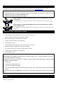
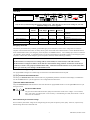
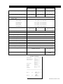
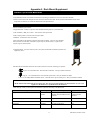
Redundant Switch User’s Manual Notice: In case of a problem with this product, do not return to the place of purchase. Go to the support page at www.apcc.com for Technical Support or call 1-800-800-4272 for prompt customer service. 990-0253A, Revision 2 6/99 Entire contents copyright ©1999 by American Power Conversion. All rights reserved. Reproduction in whole or in part without permission is prohibited. Smart-UPS is a registered trademark of APC. All other trademarks are the property of their respective owners. 990-0253A, Revision 2 6/99 English Redundant Switch User’s Manual 990-0253A, Revision 2 6/99 Table of Contents Safety ................................................................................................................................................................................................ 1 Initial Startup ..................................................................................................................................................................................... 2 Installation ......................................................................................................................................................................................... 2 Supported Configurations................................................................................................................................................................... 6 PowerChute® plus Configuration Procedure ....................................................................................................................................... 6 Storage.............................................................................................................................................................................................. 6 Operating Instructions........................................................................................................................................................................ 7 Troubleshooting Redundant Switch .................................................................................................................................................... 8 Troubleshooting the High Availability System ..................................................................................................................................... 8 Specifications .................................................................................................................................................................................... 9 Service ............................................................................................................................................................................................ 10 APC Contact Information ................................................................................................................................................................. 10 Limited Warranty ............................................................................................................................................................................. 10 Installation Tips for Rack Mount Units .............................................................................................................................................. 11 Rail Hardware .................................................................................................................................................................................. 11 990-0253A, Revision 2 6/99 Safety This section contains important instructions that should be followed during installation and maintenance of the Redundant Switch. It is intended for customers who setup, install, relocate, or maintain APC equipment. Electrical Safety • Do not work alone under hazardous conditions. • High short circuit current through conductive materials could cause severe burns. • Check that the power cord(s), plug(s), and sockets are in good condition. • To reduce the risk of electric shock when grounding cannot be verified, disconnect the equipment from the AC power outlet before installing or connecting to other equipment. Reconnect the power cord only after all connections are made. • Do not handle any kind of metallic connector before the power has been removed. • Use one hand, whenever possible, to connect or disconnect signal cables to avoid a possible shock from touching two surfaces with different electrical grounds. • Connect the equipment to a three wire AC outlet (two poles plus ground). The receptacle must be connected to appropriate branch circuit/mains protection (fuse or circuit breaker). Connection to any other type of receptacle may result in a shock hazard. CAUTION! Deenergizing Safety • To deenergize: press and hold both UPS Off buttons for more than one second to switch the equipment off. Next disconnect the equipment from the AC power outlet. • Pluggable equipment includes a protective earth conductor which carries the leakage current from the load devices (computer equipment). Total leakage current must not exceed 3.5 mA. • Use of this equipment in life support applications where failure of this equipment can reasonably be expected to cause the failure of the life support equipment or to significantly effect its safety or effectiveness is not recommended. Handling Safety ⇒ ⇒ <18 kg (<40 lb.) ⇒ 32-55 kg (70-120 lb.) 18-32 kg (40-70 lb.) • ⇒ >55 kg (>120 lb.) Be careful. Do not lift heavy loads without assistance. • Equipment with casters is built to move on a smooth surface without any obstacles. • Do not use a ramp inclined at more than 10°. • This equipment is intended for installation in a temperature-controlled (0°- 50°C, +32° - +122°F) indoor area, free of conductive contaminants. 1 990-0253A, Revision 2 6/99 Initial Startup Reminder! To obtain warranty coverage, please fill out and return the warranty registration card now. Inspection Inspect the Redundant Switch upon receipt. Notify the carrier and dealer if there is damage. The packaging is recyclable; save it for reuse or dispose of it properly. Unpacking The Redundant Switch package contains the Redundant Switch unit, its bag of hardware (OM8500), 1U mounting rails, and its bag of mounting hardware (OM-7600). Redundant Switch Hardware Kit OM8500 Part Number 1U Rails Hardware Kit OM-7600 Description Quantity Part Number Description Quantity 870-7190 Left Mounting Ear 1 870-7191 Right Mounting Ear 1 810-0002 Ornamental Screw 10-32 4 810-2004 Snap-on Speed Nut 10-32 4 820-0022 Twist Locks 2 810-2008 Cage Nut 10-32 4 808-0004 Pan Head Phillips Head Screws and Washers 4 Placement Install the Redundant Switch in a protected area that is free of excessive dust and has adequate air flow. Do not operate the Redundant Switch where the temperature and humidity are outside the specified limits. Warning Changes or modifications to this unit not expressly approved by the party responsible for compliance could void the warranty. Installation Rear Views Model CAUTION: UNINTERRUPTIBLE RISK OF ELECTRIC SHOCK. DO NOT REMOVE TOP COVER. NO USER POWER SUPPLY SERVICEABLE PARTS INSIDE. REFER SERVICING TO QUALIFIED SERVICE PERSONNEL. ACCESSORY FOR USE IN A CONTROLLED ENVIRONMENT. REFER TO MANUAL FOR ENVIRONMENTAL CONDITIONS. MADE IN USA THIS EQUIPMENT USES TWO (2) AC SOURCES MODEL : S/N: THIS DEVICE COMPLIES WITH PART 15 OF THE FCC RULES. OPERATION IS SUBJECT TO THE FOLLOWING TWO CONDITIONS: ® L I S T E D 4L 2RC6 23 9 3 8 E 9 5 4 6 3 Voltage Source Load SU041 1400 VA 120 V 2 5-15 2 5-15 SU042-1 3000 VA 120 V 2 L5-30 2 5-15 SU42-2 3000 VA 120 V 2 L5-30 1 L5-30 (captive cord) SU043 1400 VA 230 V 2 IEC 320/C14 2 IEC 320/C13 SU044-1 3000 VA 230 V 2 IEC 320/C20 1 IEC 320/C19 2 IEC 320/C13 SU045-1 3000 VA 208 V 2 L6-20 1 L6-20 (captive cord) 1.THIS DEVICE MAY NOT CAUSE HARMFUL INTERFERENCE AND 2.THIS DEVICE MUST ACCEPT ANY INTERFERENCE RECEIVED THAT MAY CAUSE UNDESIRED OPERATION. CAUTION: UNINTERRUPTIBLE RISK OF ELECTRIC SHOCK. DO NOT REMOVE TOP COVER. NO USER POWER SUPPLY SERVICEABLE PARTS INSIDE. REFER SERVICING TO QUALIFIED SERVICE PERSONNEL. ACCESSORY FOR USE IN A CONTROLLED ENVIRONMENT. REFER TO MANUAL FOR ENVIRONMENTAL CONDITIONS. MADE IN USA THIS EQUIPMENT USES TWO (2) AC SOURCES MODEL : S/N: THIS DEVICE COMPLIES WITH PART 15 OF THE FCC RULES. OPERATION IS SUBJECT TO THE FOLLOWING TWO CONDITIONS: ® L I S T E D 4L 2RC6 23 9 3 8 E 9 5 4 6 3 1.THIS DEVICE MAY NOT CAUSE HARMFUL INTERFERENCE AND 2.THIS DEVICE MUST ACCEPT ANY INTERFERENCE RECEIVED THAT MAY CAUSE UNDESIRED OPERATION. CAUTION: ® UNINTERRUPTIBLE RISK OF ELECTRIC SHOCK. DO NOT REMOVE TOP COVER. NO USER POWER SUPPLY SERVICEABLE PARTS INSIDE. REFER SERVICING TO QUALIFIED SERVICE PERSONNEL. ACCESSORY FOR USE IN A CONTROLLED ENVIRONMENT. REFER TO MANUAL FOR ENVIRONMENTAL CONDITIONS. MADE IN USA THIS EQUIPMENT USES TWO (2) AC SOURCES MODEL : S/N: THIS DEVICE COMPLIES WITH PART 15 OF THE FCC RULES. OPERATION IS SUBJECT TO THE FOLLOWING TWO CONDITIONS: L I S T E D 4L 2RC6 23 9 3 8 E 9 5 4 6 3 1.THIS DEVICE MAY NOT CAUSE HARMFUL INTERFERENCE AND 2.THIS DEVICE MUST ACCEPT ANY INTERFERENCE RECEIVED THAT MAY CAUSE UNDESIRED OPERATION. INPUT VOLTAGE: 220-240VAC MODEL 1400 3000 G e p r ü f t e S i c h e r h e i t MODEL : S/N: MAX I 8A 16A SEE OWNER'S MANUAL INPUT VOLTAGE: 2 x AC 220-240V; 50-60Hz MODEL : MODEL INPUT OUTPUT S/N: S U 0 4 3 2 x 8 A ( 1 4 0 0 V A2) x A C 2 2 0 - 2 4 0 V ; 2 x 8 A G e p r ü f t e S i c h e r h e i t S U 0 4 4 - 12 x 1 6 A ( 3 0 0 0 V A 2 )x A C 2 2 0 - 2 4 0 V ; 1 x 1 6 A , 2 x 8 A SU044-2 x16A (3000V2 A )x AC 220-240V;2x16A CAUTION: ® UNINTERRUPTIBLE RISK OF ELECTRIC SHOCK. DO NOT REMOVE TOP COVER. NO USER POWER SUPPLY SERVICEABLE PARTS INSIDE. REFER SERVICING TO QUALIFIED SERVICE PERSONNEL. ACCESSORY FOR USE IN A CONTROLLED ENVIRONMENT. REFER TO MANUAL FOR ENVIRONMENTAL CONDITIONS. MADE IN USA THIS EQUIPMENT USES TWO (2) AC SOURCES MODEL : S/N: THIS DEVICE COMPLIES WITH PART 15 OF THE FCC RULES. OPERATION IS SUBJECT TO THE FOLLOWING TWO CONDITIONS: L I S T E D 4L 2RC6 23 9 3 8 E 9 5 4 6 3 1.THIS DEVICE MAY NOT CAUSE HARMFUL INTERFERENCE AND 2.THIS DEVICE MUST ACCEPT ANY INTERFERENCE RECEIVED THAT MAY CAUSE UNDESIRED OPERATION. 990-0253A, Revision 2 6/99 2 1. Install Redundant Switch. •Before plugging in the unit, install any compatible SmartSlot accessory (check our website at www.apcc.com). Follow the installation instructions that come with the accessory. Notes: 1. This Redundant Switch is equipped with a SmartSlot for additional manageability. See the APC Website (www.apcc.com) for information on plug-in accessories. 2. SNMP accessories are currently unsupported in the Redundant Switch SmartSlot. Manage the preferred Smart-UPS via SNMP by plugging the Web/SNMP Management Card into the Smart-UPS SmartSlot. 3. Other compatible Accessories must be put into the Redundant Switch, not the UPS. 4. The Redundant Switch inlets are the main disconnect devices. 5. For multiple SmartSlot accessory configurations, please visit our Website (www.apcc.com). •Follow the installation instructions in the UPS’s User’s Manual to install the UPS. •Plug the power cords attached to the Redundant Switch into each UPS. •Both UPS units should be the same sine-wave model. Note: Ears and 1U rails for rack mounting the Redundant Switch (into a four-post rack) are included with the unit. Follow the instructions below to mount the Redundant Switch, and route the cables for maximum accessibility. Mount the Ears 1. Œ • Œ Two ears are available for the Redundant Switch. Each ear has four mounting holes, as shown to the left (the ear itself hides the front hole). 2. The sides of the Redundant Switch have four matching holes at the front. To leave room to route the cables and place the connectors flush with the front of the rack, align the second hole from the front of each ear, shown at Œ, above, with the front hole in the corresponding side of the Redundant Switch. (This may vary align the two holes that best meet your needs.) Secure the ear to the Redundant Switch with the provided screws. The ears should then be forward of the front of the Redundant Switch and at right angles away from it, so that they can be attached to the rack. The adjacent figure shows a Redundant Switch with the ears mounted. 3 990-0253A, Revision 2 6/99 Install the Rails Note: The mounting rails are only necessary if you are using a four-post rack. If you are using a two-post rack the Redundant Switch will be mounted by the ears alone. Skip to Connect and Route the Cables. Two rails and associated hardware are included with the Redundant Switch. For information on which clips and screws the rack you are using requires, see Appendix A: Rack Mount Supplement. Prepare the rack’s rail-holes to mount the Redundant Switch’s ears and rails as appropriate. • • Ž The rails are adjustable and can be disassembled by removing the slide screw and nut, shown at •, above. Disassemble the rails. Set the screws, nuts, and the front segments, • , aside. 1. Mount the ears of the rear rail segments, Ž, to the rear rack rails on the prepared rack using appropriate rack hardware. 2. The sides of the Redundant Switch have two holes at the rear. Align the top two holes on the front rail segment, • , with the two holes at the rear of the Redundant Switch and secure them with the tapered head screws provided. Connect and Route the Cables 990-0253A, Revision 2 6/99 3. Connect the communication cables to the front of the Redundant Switch. 4. If the accessories and options you are using require front cable connections, connect these also. 5. Route the cables around the Redundant Switch using the side channels, so that they can be connected to the appropriate equipment mounted in the rack. Arrows in the adjacent figure indicate the side channels. 6. Install one or both of the enclosed plastic twist locks to secure the cables, if desired. The arrow in the adjacent figure shows one twist lock mounted to the side of the Redundant Switch. 4 Mount the Redundant Switch in the Rack Note: Two people should perform this step. 1. Position the Redundant Switch forward of the mounted rear rail segments. 2. Align the front and rear rail segments and slide the front segment onto the rear segment. 3. Align the Redundant Switch ears with the front rack rails and use rack hardware to secure the mounting ears to the rack rails. 4. From the rear of the rack, insert and tighten the slide screws and nuts. 2. Connect Equipment. • Do not power laser printers through the Redundant Switch. • Use your server’s power cords to connect to the Redundant Switch. • Install the 940-1000A communication cable(s) between each UPS and the Redundant Switch. Make sure that the communications cable for the preferred UPS, UPS-A, and the power cord for UPS-A are connected to the same UPS. Note: If you have more loads to connect than there are outlets provided, use a power strip. Visit APC's Website (www.apcc.com) for rack mountable multiple outlet solutions. 3. Turn on Redundant Switch. • • Turn on all connected equipment. Press the ON switch of UPS-A to turn on your Redundant Switch and UPS-B. This will power-up connected equipment. Note: To test whether the cabling is correct, shut off one UPS using its OFF button. If it turns back on, the cabling is correct. If not, swap the two UPS communication cables. 4. Connect PowerChute Cable. • When you are ready to install PowerChute® plus, install the PowerChute® plus communication cable between the Redundant Switch’s server port and the server’s serial port. Note: When managed by PowerChute® plus UPS software, the Redundant Switch should be used with servers running Windows NT, Solaris, or Netware. 5 990-0253A, Revision 2 6/99 Supported Configurations Two supported connection configurations for Redundant Switch are illustrated below. For detailed information on these configurations and other supported configurations, please visit the APC Website at http://www.apcc.com. Notes: • Redundant Switch does not support communications with accessories installed in the UPS, except for SNMP accessories. Install any other accessory you need in Redundant Switch. • Both UPS units should be the same sine-wave model. Better Configuration: Smart-UPS Redundant Switch with two Smart-UPS units connected to one AC line. This configuration is the minimal acceptable, since both UPS units depend on one facility power source. Best Configuration: Smart-UPS Redundant Switch with two Smart-UPS units connected to two separate AC lines. This configuration is better than the previous, since each UPS unit receives power from a separate facility power source. PowerChute® plus Configuration Procedure 1. Install PowerChute® plus following the instructions in the enclosed Software Installation Instruction Sheet. 2. At the Redundant Switch front panel, set the Source Preference to Source B. 3. Start the computer on which PowerChute® plus is installed. 4. Start PowerChute® plus. Communication is to UPS-B. 5. Configure UPS-B according to your requirements. 6. Set the UPSID to UPS_B. 7. At the Redundant Switch front panel, set the Source Preference to Source A. 8. Restart the computer on which PowerChute® plus is installed. 9. Start up PowerChute® plus. By default, communication is to UPS-A. 10. Configure UPS-A according to your requirements. 11. Set the UPSID to UPS_A. Notes: High availability is the condition in which both UPSs are available to supply AC power. Standard availability is when only one UPS is fully available for back up power. The following events result in a “self test failed: invalid test” message from PowerChute which indicates a change from high availability to standard availability: ⇒ Self-test fails ⇒ Alternate UPS communication is lost ⇒ Alternate UPS voltage is out of range ⇒ UPS-A fails, Redundant Switch senses this and transfers the load’s AC power input and PowerChute communication to UPS-B. When the selected UPS self-tests, Redundant Switch switches to the other UPS, causing a self-test of that UPS, then switches back. Storage Store the Redundant Switch covered and upright in a cool, dry location at -15 to +50 °C (+5 to +122 °F). 990-0253A, Revision 2 6/99 6 Operating Instructions Front View Status Status Select Select To UPS B Level R T N I + N 2 4 AC Source A B To UPS A To Server Function Bright Source selected EPO Dim Emergency Power Off Off Source OK, but not selected Source not OK Redundant Switch Note: Only the Factory Default settings shown below should be used. Check that these are the current settings for your unit. Additional setting are for future upgrades. Function Source A Sensitivity Factory Default Reduced User Selectable Choices LED Bright LED Dim LED Off Normal Reduced Low Source B Sensitivity Reduced Normal Reduced Low Source Preference Source A Xfer Voltage Source B Xfer Voltage Source A Medium Medium Source A Narrow Narrow Source B Medium Medium None Wide Wide Description Sets transfer sensitivity to line conditions Sets transfer sensitivity to line conditions Selects the preferred AC source Sets the transfer voltage window Sets the transfer voltage window Emergency Power Off The UPS may be switched off by a remotely operated Emergency Power Off (EPO) control. Such a configuration is common in computer rooms and laboratories where, for safety reasons, power to the loads must be disconnected. To connect Redundant Switch and its attached Smart-UPS to your emergency power off system, use the EPO connector. Use a normally-open contact to connect the +24 terminal to the IN terminal. A certified electrician can wire the external blue four-pin female connector to the emergency power off system. If this is done, and the emergency power off system is activated, neither UPS will go on-battery. Cautions The EPO interface is a Safety Extra Low Voltage (SELV) circuit and may be connected only to other SELV circuits. The EPO interface is designed to monitor circuits that have no determined voltage potential. Such closure circuits may be provided by a switch or relay properly isolated from the utility. Connection of the EPO interface to any circuit other than a closure type circuit may cause damage to the Redundant Switch. Front Panel User Programming User programmable settings are accessible using controls located on the Redundant Switch front panel. Function Select LED Indicator The three green Function Select LEDs indicate which user programmable parameter is selected for status display or modification. Use the left Select button to cycle through the five user configurable items listed above. Function Status LED Indicator The green Function Status LED indicates the state of the selected user programmable function. Use the right Select button to cycle among the choices. AC Source LED Indicator The green on-line LED indicates the line quality and select status of each source: Bright = source selected; Dim = source okay, not selected; Off = source not okay; 1 second flashing of 1 LED, other LED off = both AC sources are out of tolerance. Source Sensitivity and Transfer Voltage Source sensitivity and transfer voltage can be changed using the front panel to adjust for power quality. However, only the factory default settings shown above should be used. 7 990-0253A, Revision 2 6/99 Troubleshooting Redundant Switch Note: Only APC Support Personnel should open the Redundant Switch for repair. Problem Possible Cause Redundant Switch will not turn on. Very low or no utility voltage. Corrective Action Check the AC power supply to the Redundant Switch with a table lamp. If very dim, have the utility voltage checked. Check that AC plugs are properly connected between Redundant Switch and the UPSs. Server cannot communicate with attached UPS through Redundant Switch. Cabling problem or internal Redundant Switch fault. Check the cable connections. If they are tight and there is still no communication, connect the server directly to a UPS. If there is now communication, there is an internal Redundant Switch fault. In any case, Contact APC customer service (see Service section). All Redundant Switch LEDs are flashing. Internal, automated self-test failure: defective unit See Service section, below. For Computer Interface Port Specifications, see the APC Website (www.apcc.com). Troubleshooting the High Availability System With the High Availability System, the attached UPSs are polled continuously for capability to carry a load and ability to communicate with the management software (PowerChute plus®). When a problem with one of the UPSs in the High Availability System occurs, the load is not interrupted and polling continues, but PowerChute plus® is alerted immediately. PowerChute plus® responds by displaying the message: “self test failed: invalid test”. Communications Problems If there is a communications problem with either UPS; i.e., the above message is reported continually, first diagnose the communications path between the UPSs and the Redundant Switch. If the communications path appears to be good, check the front panel of the Redundant Switch. If the Status Select LEDs are flashing in any sequence, the Redundant Switch has failed. In this case, troubleshoot the Redundant Switch using the Troubleshooting instructions above. If you need further assistance, follow the instructions in the Service section below. If this is a UPS or server communications problem, the front panel may look normal. In this case, troubleshoot the UPS using the Troubleshooting instructions in the Smart-UPS Quick Reference Guide included with the UPSs. If you need further assistance, follow the instructions in the Service section of the User’s Manual. Loss of Redundancy Problems If the Redundant Switch LED for UPS-B is dark, UPS-B has lost the ability to deliver a load when engaged. Similarly, if the LED for UPS-A is dark, it has failed and power is now coming from UPS-B. Troubleshoot the UPS using the Troubleshooting instructions in the Smart-UPS Quick Reference Guide included with the UPSs. If you need further assistance, follow the instructions in the Service section of the User’s Manual. If PowerChute plus® displays the message “self test failed: invalid test” for a short time or several times. UPS-A has dropped output voltage. Initiate a self test through PowerChute plus®. If the self test fails, troubleshoot the UPS using the Troubleshooting instructions in the Smart-UPS Quick Reference Guide included with the UPSs. If you need further assistance, follow the instructions in the Service section of the User’s Manual. 990-0253A, Revision 2 6/99 8 Specifications SU041, SU042-1, SU042-2 SU045-1 SU043, SU044 Acceptable input voltage 120 VAC: 0 - 165 VAC 208 VAC: 0 - 275 VAC 230 VAC: 0 - 325 VAC Output voltage (by default when used with Smart-UPS) 120 VAC: 108 - 132 VAC 208 VAC: 187 - 229 VAC 230 VAC: 207 - 253 VAC Frequency limits (on-line operation) 47 -63 Hz. Transfer Times 60 Hz Normal 4 ms, typical, 8 ms, maximum 60 Hz Reduced 8 ms, typical, 16 ms, maximum 50 Hz Normal 5 ms, typical, 10 ms, maximum 50 Hz Reduced 10 ms, typical, 20 ms, maximum Maximum load 1400 VA: 12A 3000 VA: 24 A 3000 VA: 14 A 1400 VA: 6 A 3000 VA: 13 A Operating temperature 0 to +50°C (+32 to +122°F) Storage temperature -15 to +50°C (+5 to +122°F) Operating and storage relative humidity 0 to 95%, non condensing Operating elevation 0 to +3,000 m ( 0 to +10,000 ft) Storage elevation 0 to +15,000 m (0 to +50,000 ft) Electromagnetic immunity IEC 801-2, 801-3, 801-4 Audible noise in dBA @ 1 m (3 ft) <45 Size (H x W x D) 4.45 x 43.2 x 19 cm (1.75 x 17.0 x 7.5 in) Weight - net (shipping) 4.5 (6.8) kg / 10 (15) lb Safety approvals Listed to UL 1778, certified to CSA 107.1 GS licensed by VDE to EN 50091 and 60950 EMC verification FCC Class A certified CISPR 22 Class A verified 9 990-0253A, Revision 2 6/99 Service If the UPS requires service do not return it to the dealer! Follow these steps: 1. Use the Troubleshooting sections of this manual and the UPS User’s Manual to eliminate common problems. 2. Verify that no circuit breakers are tripped. A tripped circuit breaker is the most common problem! 3. If the problem persists, call customer service or visit the APC Internet Website (www.apcc.com). 4. Note the model numbers and serial numbers of the UPSs and the Redundant Switch and the date(s) purchased. A technician will ask you to describe the problem and try to solve it over the phone, if possible. If this is not possible the technician will issue a Return Merchandise Authorization Number (RMA#). 5. If the Redundant Switch is under warranty, repairs are free. If not, there is a repair charge. 6. Pack the Redundant Switch in its original packaging. If the original packing is not available, ask customer service about obtaining a new set. 7. Pack the Redundant Switch properly to avoid damage in transit. Never use Styrofoam beads for packaging. Damage sustained in transit is not covered under warranty. 8. Include a letter with your name, RMA#, address, copy of the sales receipt, description of the trouble, your daytime phone number, and a check (if necessary). 9. Mark the RMA# on the outside of the package. 10. Return the Redundant Switch by insured, prepaid carrier to the address given to you by Customer Service. APC Contact Information USA/Canada. … … … … … . Mexico… … … … … … … … Brazil … … … … … … … … . Worldwide … … … … … … Internet and Tech Support 1.800.800.4272 292.0253 / 292.0255 0800.12.72.1 1.401.789.5735 http://www.apcc.com Limited Warranty American Power Conversion (APC) warrants its products to be free from defects in materials and workmanship for a period of two years from the date of purchase. Its obligation under this warranty is limited to repairing or replacing, at its own sole option, any such defective products. To obtain service under warranty you must obtain a Returned Material Authorization (RMA) number from customer support (see the Service section of the User’s Manual). Products must be returned with transportation charges prepaid and must be accompanied by a brief description of the problem encountered and proof of date and place of purchase. This warranty does not apply to equipment which has been damaged by accident, negligence, or misapplication or has been altered or modified in any way. This warranty applies only to the original purchaser who must have properly registered the product within 10 days of purchase. EXCEPT AS PROVIDED HEREIN, AMERICAN POWER CONVERSION MAKES NO WARRANTIES, EXPRESSED OR IMPLIED, INCLUDING WARRANTIES OF MERCHANTABILITY AND FITNESS FOR A PARTICULAR PURPOSE. Some states do not permit limitation or exclusion of implied warranties; therefore, the aforesaid limitation(s) or exclusion(s) may not apply to the purchaser. EXCEPT AS PROVIDED ABOVE, IN NO EVENT WILL APC BE LIABLE FOR DIRECT, INDIRECT, SPECIAL, INCIDENTAL, OR CONSEQUENTIAL DAMAGES ARISING OUT OF THE USE OF THIS PRODUCT, EVEN IF ADVISED OF THE POSSIBILITY OF SUCH DAMAGE. Specifically, APC is not liable for any costs, such as lost profits or revenue, loss of equipment, loss of use of equipment, loss of software, loss of data, costs of substitutes, claims by third parties, or otherwise. 990-0253A, Revision 2 6/99 10 Appendix A: Rack Mount Supplement Installation Tips for Rack Mount Units Please observe the following items when installing the Rack Mount Redundant Switch: •The Redundant switch is furnished with brackets for mounting in standard 19” (46.5 cm) rack mount brackets. •Select a rack location with adequate air flow that is free from excessive dust. Do not operate the Redundant Switch where temperature or humidity are outside the limits listed under Specifications. Rail Hardware There are different types of racks: •Equipment Rack - usually an open rack with threaded mounting holes or no threaded holes. •APC Netshelter , IBM, Vero, others - enclosed rack with square holes •Dell, Compaq, Rittal - enclosed rack with square holes •HP Rack - enclosed rack with round holes These racks differ in the methods required for mounting equipment. They may have threaded holes (hardware not included), round holes (require clip nut, shown below), or square holes (require cage nut, shown below). •Telecomm Rack - open rack with two poles / four poles and threaded round holes (hardware not supplied by APC). Included with the Redundant Switch are two kinds of nuts and screws for mounting your product: • Clip nut 10-32 internal thread - best used with round holes - APC part number 810-2004 • Cage nut - 10-32 internal thread - best used with square holes - APC part number 810-2008 •Screw 10-32 Phillips Head Ornamental Screw - used with above clip nut and cage nut - APC part number 810-0002 Note: Racks with threaded round holes do not require nuts. APC does not provide hardware for threaded racks. See your rack supplier for this hardware or specifications for this hardware. Check the type of rack you have against the hardware required for mounting in the table below. Rack Type Hole Type Hardware Required Hardware Included Equipment Rack Threaded, or No Threads See rack specifications if threaded. If not threaded use APC hardware N/A if threaded. If not threaded use APC hardware. Netshelter/Compaq/IBM/Dell Square Cage nut, 10-32 screws 810-2008, 810-0002 HP Round Clip nut, 10-32 screws 810-2004, 810-0002 Telecomm Threaded See rack specifications N/A 11 990-0253A, Revision 2 6/99