1
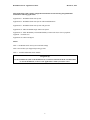
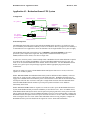
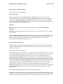
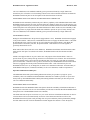
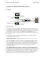
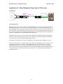
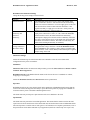
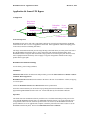
Redundant Switch - Applications Guide
March 22, 1999
Redundant Switch
Applications Guide
1
Redundant Switch - Applications Guide
March 22, 1999
This Applications Guide contains configuration information for the following using Redundant
Switch in the following applications:
Application #1 - Redundant Smart-UPS System
Application #2 - Redundant Smart-UPS System with Extended Runtime
Application #3 - Redundant Smart-UPS System with generator
Application #4 - Phase Redundant Single Smart-UPS System
Application #5 - Phase Redundancy and UPS Redundancy to Microsoft Cluster Server peripheral
equipment - Available soon.
Application #6. Smart-UPS Bypass
Tables:
Table 1 - Redundant Switch Factory Preset Default Settings
Table 2. PowerChute plus Supported operating systems
Table 3. Available Redundant Switch Models
Navigation Tip
Use the bookmark list (click on the bookmark icon, second icon from the left in the Acrobat toolbar
to view the bookmarks) to move to the Application or Table you wish to review.
2
Redundant Switch - Applications Guide
March 22, 1999
Application #1 - Redundant Smart-UPS System
Configuration
Smart-UPS "A"
communications
AC - phase 1
A
Power to
Redundant Switch
Status
Status Select
Select
Level
R
T
N
I +
N 2
4
To UPS B
AC Source
B
A
To UPS A
To Server
Power
to Load
Function
Bright
Source selected
EPO
Emergency
Power Off
Dim
Source OK, but not selected
Off
Source not OK
Redundant Switch
B
B
AC - phase 1
or independent
phase (phase 2)
Redundant
Switch
A
communications
communications
Smart-UPS "B"
Goals and objectives
The Redundant Smart-UPS System created with the Redundant Switch provides a very high level of AC
power availability and continuous availability of safe server shutdown. This very high level of availability is
recommended for server applications where the downtime costs are high and data recovery time is lengthy.
The Redundant Smart-UPS System adds a level of redundancy and hot swappability to the power
protection system compared to a single UPS. This provides a substantial increase to system
MTBF(meantime between failure) over that of a single UPS.
In some cases, users may need to connect multiple loads to Redundant Switch. When additional receptacles
are needed, one may purchase the MO9RM. It is APC's Rack Mount Multi-Outlet Strip for 120V 15A
loads. It can be used with Redundant Switch models; SU041 and SU042-2. For other Redundant Switch
models, use a generic power strip with surge suppression and the appropriate plug and receptacle
combinations.
The user can supply AC power to the Redundant Smart-UPS System from one AC circuit, or from two
separate AC circuits (or phases).
Case 1. One AC Circuit: The Redundant Smart-UPS system has full Smart-UPS redundancy in the case
where one AC circuit is used to supply power to both Smart-UPS units. Redundant Switch proactively
engages the redundant Smart-UPS to deliver power to the load when it senses that the selected Smart-UPS
will drop the load. The user can remove and replace a single Smart-UPS unit while the redundant SmartUPS unit and Redundant Switch continue to provide power protection and safe server shutdown
functionality to the loads.
Case 2. Two AC Circuits: When two separate AC circuits are used to power the Redundant Smart-UPS
System, the Redundant Switch provides the redundancy as described in Case 1, above. In addition to this,
the Redundant Smart-UPS System offers users the option of specifying which AC source powers the loads.
This is useful when there is a need for scheduled downtime of one AC circuit or Smart-UPS. Configure the
Redundant Switch (front panel selection) to power the loads from one AC circuit / Smart-UPS combination
while servicing the other AC circuit / Smart-UPS combination. When servicing completes, configure the
Redundant Switch to power the loads from the original AC circuit / Smart-UPS combination.
3
Redundant Switch - Applications Guide
March 22, 1999
Redundant Switch Function Settings
Use the factory preset settings (defaults).
Smart-UPS Settings
Follow the information given in the Smart-UPS User’s Manual to select the correct Smart-UPS
configuration for the power environment. Follow the Redundant Switch PowerChute plus Configuration
Procedure in the Redundant Switch User’s Manual if you plan to protect a server running a supported
operating system with this Redundant Smart-UPS system. This procedure guides you through configuring
the Smart-UPS units using the Redundant Switch.
Installation
Smart-UPS units: Follow the instructions and procedure given in the Smart-UPS Rack Mount
Supplement.
Redundant Switch: Redundant Switch mounts in the front or rear of a standard 19” cabinet, occupying
1U of rack space.
Follow the Redundant Switch User’s Manual Initial Start-Up instructions. Follow the Redundant Switch
PowerChute plus Configuration Procedure if you are using the Redundant Smart-UPS System with a server
running a supported OS and plan to manage the system using PowerChute plus. Refer to Table 2.
PowerChute plus Supported Operating Systems, below.
Operation with PowerChute plus
The Redundant Smart-UPS System running PowerChute plus provides very high AC power availability.
This is the condition in which both Smart-UPS units are available to provide AC power, battery back up,
and safe server shutdown.
MONITORING HIGH AVAILABILITY
The Redundant Smart-UPS System checks the availability of both Smart-UPS units each time a Smart-UPS
self test is initiated through PowerChute plus. The Smart-UPS is preset to schedule self-tests every two
weeks. You can change the periodic self test interval to suit the needs of your application (refer to
PowerChute plus User’s Manual Configuration / Schedule Tests and Shutdown). Initiating the self - test
from PowerChute Plus executes self - tests on both the preferred and the redundant UPS (UPS-A and UPSB, respectively). When both UPS-A and UPS-B pass self tests, PowerChute plus records the event with the
message: Self Test Passed. Self tests of both Smart-UPS units can also be executed when a self test is
initiated locally on UPS-A. If either Smart-UPS unit fails its self test, PowerChute plus records the event
with the message: Self Test Failed: Invalid Test. With one Smart-UPS unit failing its self test, the
Redundant Smart-UPS System is still providing clean AC power, battery back up, and safe server shutdown
functionality through the other Smart-UPS unit. Visit the installation to further diagnose the situation /
restore the System,
SWITCHING FROM PREFERRED SOURCE TO REDUNDANT SOURCE
Redundant Switch switches load delivery and communications to the redundant Smart-UPS when it detects
that the power feed from Source A is unable to deliver power to the load. In this case, the availability of the
system drops from very high (with both Smart-UPS available to provide AC power, battery back up, and
4
Redundant Switch - Applications Guide
March 22, 1999
safe server shutdown) to the standard availability power protection afforded by a single Smart-UPS.
PowerChute plus records the event of switching to Source B as Self Test Failed: Invalid Test. Examine the
Redundant Switch front panel or the front panels of the Smart-UPS units for details.
MONITORING THE AVAILABILITY OF THE REDUNDANT SMART-UPS
Redundant Switch continuously monitors the power delivery capability of the redundant Smart-UPS. When
Redundant Switch senses that its power feed from Source B is unable to deliver power to the load (if it were
to be engaged) PowerChute plus records the event as Self Test Failed: Invalid Test. Examine the Redundant
Switch front panel or the front panels of the Smart-UPS units for details. In this case, the availability of the
system drops from very high (with both Smart-UPS available to provide AC power, battery back up, and
safe server shutdown) to the standard availability power protection afforded by a single Smart-UPS.
EXTENDED BLACKOUT
During an extended blackout to the preferred (engaged) Smart - UPS, Redundant Switch remains engaged
to the preferred Smart - UPS (UPS-A). Redundant Switch does not engage the alternate Smart - UPS (UPSB) automatically since it does not sense an AC power fault from the preferred Smart - UPS. When the
preferred Smart - UPS battery runs low, the preferred Smart - UPS and the server work together to
gracefully shut down the server.
When UPS-A shuts down (after safe server shutdown), Redundant Switch shuts down the alternate Smart UPS, UPS-B. After power is restored to the UPS-A, Redundant Switch resets the alternate UPS-B to
operate.
UPS-B is not tapped to deliver AC power in this case. The purpose of the alternate Smart - UPS is to
provide clean AC power, battery back-up, and safe server shutdown in case of failure. The user should not
expect the alternate Smart - UPS to provide extended run time. If a single AC circuit that was supplying
power to both Smart - UPS units were to go down, PowerChute plus and Redundant Switch can not extend
run time by toggling between the preferred and the alternate Smart - UPS. If PowerChute plus and
Redundant Switch were to try to manage this, an unsafe server shutdown could result - the functionality of
the Redundant UPS System, continuous availability of safe server shutdown, would be compromised.
Operation without PowerChute plus:
The Redundant Smart-UPS System running without PowerChute plus provides very high AC power
availability. This is the condition in which both Smart-UPS units are available to provide AC power and
battery back up. The Redundant Smart-UPS System running without PowerChute plus does not provide
safe server shutdown functionality.
MONITORING HIGH AVAILABILITY
Redundant Switch of the Redundant Smart-UPS System checks the availability of both Smart-UPS units to
deliver power to the load. You can view the availability of both UPS-A and UPS-B at the Redundant Switch
front panel (refer to the Redundant Switch User’s Manual).
The Smart-UPS units are preset to self-test every two weeks. Self tests of both Smart-UPS units can also be
executed when a self test is initiated locally on UPS-A. If one Smart-UPS unit fails its self test, the
Redundant Smart-UPS System is still providing clean AC power and battery back up functionality through
the other Smart-UPS unit. Check the installation to further diagnose the situation / restore the System,
5
Redundant Switch - Applications Guide
March 22, 1999
SWITCHING FROM PREFERRED SOURCE TO REDUNDANT SOURCE
Redundant Switch switches load delivery to the redundant Smart-UPS when it detects that the power feed
from Source A is unable to deliver power to the load. In this case, the availability of the system drops from
very high (with both Smart-UPS available to provide AC power and battery back up) to the standard
availability power protection afforded by a single Smart-UPS. Examine the Redundant Switch front panel or
the front panels of the Smart-UPS units to determine availability.
MONITORING THE AVAILABILITY OF THE REDUNDANT SMART-UPS
Redundant Switch continuously monitors the power delivery capability of the redundant Smart-UPS. When
Redundant Switch senses that its power feed from Source B is unable to deliver power to the load (if it were
to be engaged) it indicates so on the front panel (AC Source LED Indicators). Examine the Redundant
Switch front panel or the front panels of the Smart-UPS units for details. In this case, the availability of the
system drops from very high (with both Smart-UPS available to provide AC power and battery back up) to
the standard availability power protection afforded by a single Smart-UPS.
EXTENDED BLACKOUT
During an extended blackout to the preferred (engaged) Smart-UPS, Redundant Switch remains engaged to
the preferred Smart - UPS (UPS-A). Redundant Switch does not engage the alternate Smart - UPS (UPS-B)
automatically since it does not sense an AC power fault from the UPS-A (which switches to On Battery).
When the UPS-A battery runs low, it continues to supply the load, further draining. When the UPS-A
battery is fully depleted, the Redundant Switch senses that the load will be dropped, and switches
immediately to selecting Source B (UPS-B), thereby keeping the load powered.
After power is restored to the UPS-A, Redundant Switch switches back to selecting power from this UPS.
UPS-B is tapped to deliver AC power in this case. Without the safe shutdown functionality that the power
protection system supplies to a server load via PowerChute plus, Redundant Switch acts as a static transfer
switch. The user can expect to use the run time of both UPS-A and UPS-B. Ideally, different phases of AC
power should be used to feed UPS-A and UPS-B. This way, an extended blackout to one phase can occur
and as long as the other phase remains up, the load will not suffer downtime.
6
Redundant Switch - Applications Guide
March 22, 1999
Application #2 - Redundant Smart-UPS XL System
Configuration
Smart-UPS XL Battery Pack(s)
communications
AC - phase 1
Smart-UPS XL "A"
A
Power to
Redundant Switch
Smart-UPS XL "B"
AC - phase 1
or independent
phase (phase 2)
Redundant
Switch
A
Status
Status Select
Select
Level
R
T
N
I +
N 2
4
To UPS B
AC Source
A
B
To UPS A
To Server
Power
to Load
Function
Bright
Source selected
EPO
Emergency
Power Off
B
Dim
Source OK, but not selected
Off
Source not OK
Redundant Switch
B
communications
communications
Goals and objectives
The Redundant Smart-UPS System created with Redundant Switch enables provides very high level of AC
power availability and continuous availability of safe server shutdown. This very high level of availability is
recommended for server applications where the downtime costs are high and data recovery time is lengthy.
The Redundant Smart-UPS System adds a level of redundancy and hot swappability to the power
protection system compared to a single UPS. This provides a substantial increase to system MTBF over that
of a single UPS.
Use of an extended run battery configuration provides an additional level of availability by extending
system ridethrough during power outages.
The user can supply AC power to the Redundant Smart-UPS System from one AC circuit, or from two
separate AC circuits (or phases).
Case 1. One AC Circuit: The Redundant Smart-UPS system has full Smart-UPS redundancy in the case
where one AC circuit is used to supply power to both Smart-UPS units. Redundant Switch proactively
engages the redundant Smart-UPS to deliver power to the load when it senses that the selected Smart-UPS
will drop the load. The user can remove and replace a single Smart-UPS unit while the redundant SmartUPS unit and Redundant Switch continue to provide power protection and safe server shutdown
functionality to the loads.
Case 2. Two AC Circuits: When two separate AC circuits are used to power the Redundant Smart-UPS
System, Redundant Switch provides the redundancy as described in Case 1, above. In addition to this, the
Redundant Smart-UPS System offers users the option of specifying which AC source powers the loads. This
is useful when there is a need for scheduled downtime of one AC circuit or Smart-UPS. Configure the
Redundant Switch (front panel selection) to power the loads from one AC circuit / Smart-UPS combination
while servicing the other AC circuit / Smart-UPS combination. When servicing completes, configure
Redundant Switch to power the loads from the original AC circuit / Smart-UPS combination.
7
Redundant Switch - Applications Guide
March 22, 1999
Redundant Switch Function Settings
Use the factory preset settings (defaults).
Smart-UPS Settings:
Follow the information given in the Smart-UPS User’s Manual to select the correct Smart-UPS
configuration for the power environment. Follow the Redundant Switch PowerChute plus Configuration
Procedure in the Redundant Switch User’s Manual if you plan to protect a server running a supported
operating system with this Redundant Smart-UPS system. This procedure guides you through configuring
the Smart-UPS units using Redundant Switch.
Installation
Smart-UPS units: Follow the instructions and procedure given in the Smart-UPS Rack Mount
Supplement.
Redundant Switch: Redundant Switch mounts in the front or the rear of a standard 19” cabinet, occupying
1U of rack space.
Follow the Redundant Switch User’s Manual Initial Start-Up instructions.
Follow the Redundant Switch PowerChute plus Configuration Procedure in the Redundant Switch User’s
Manual if you are using the Redundant Smart-UPS System with a server running a supported OS and plan
to manage the system using PowerChute plus.
Note the following change to the setup procedure: When configuring the number of battery packs with
PowerChute do not set the value to be the same in both UPS XL units. Set the value to be programed into
each Smart-UPS XL equal to the actual number of battery packs connected to the rear of each Smart-UPS
XL. If this is not done properly the runtime will not indicate correctly if the alternate UPS is activated. This
can result in a failure of safe server shutdown capability.
Refer to Table 2. PowerChute plus Supported Operating Systems, below.
Operation with PowerChute plus
The Redundant Smart-UPS System running PowerChute plus provides very high AC power availability.
This is the condition in which both Smart-UPS units are available to provide AC power, battery back up,
and safe server shutdown.
MONITORING HIGH AVAILABILITY
The Redundant Smart-UPS System checks the availability (including battery run time) of both Smart-UPS
units each time a Smart-UPS self test is initiated through PowerChute plus. The PowerChute plus software
is preset to schedule a Smart-UPS periodic self-test every two weeks. You can change the periodic self test
interval to suit the needs of your application (refer to PowerChute plus User’s Manual Configuration /
Schedule Tests and Shutdown). Initiating the self - test from PowerChute Plus executes self tests on both the
preferred and the redundant UPS (UPS-A and UPS-B, respectively). When both UPS-A and UPS-B pass
self tests, PowerChute plus records the event with the message: Self Test Passed. Self tests of both SmartUPS units can also be executed when a self test is initiated locally on UPS-A. If either Smart-UPS unit
fails its self test, PowerChute plus records the event with the message: Self Test Failed: Invalid Test. With
one Smart-UPS unit failing its self test, the Redundant Smart-UPS System is still providing clean AC
8
Redundant Switch - Applications Guide
March 22, 1999
power, battery back up, and safe server shutdown functionality through the other Smart-UPS unit. Visit the
installation to further diagnose the situation / restore the System,
SWITCHING FROM PREFERRED SOURCE TO REDUNDANT SOURCE
Redundant Switch switches load delivery and communications to the redundant Smart-UPS when it detects
that the power feed from Source A is unable to deliver power to the load. In this case, the availability of the
system drops from very high (with both Smart-UPS available to provide AC power, battery back up, and
safe server shutdown) to the standard availability power protection afforded by a single Smart-UPS.
PowerChute plus records the event of switching to Source B as Self Test Failed: Invalid Test. Examine the
Redundant Switch front panel or the front panels of the Smart-UPS units for details.
MONITORING THE AVAILABILITY OF THE REDUNDANT SMART-UPS
Redundant Switch continuously monitors the power delivery capability of the redundant Smart-UPS. When
Redundant Switch senses that its power feed from Source B is unable to deliver power to the load (if it were
to be engaged) PowerChute plus records the event as Self Test Failed: Invalid Test. Examine the Redundant
Switch front panel or the front panels of the Smart-UPS units for details. In this case, the availability of the
system drops from very high (with both Smart-UPS available to provide AC power, battery back up, and
safe server shutdown) to the standard availability power protection afforded by a single Smart-UPS.
EXTENDED BLACKOUT
During an extended blackout to the preferred (engaged) Smart - UPS, Redundant Switch remains engaged
to the preferred Smart - UPS (UPS-A). Redundant Switch does not engage the alternate Smart - UPS (UPSB) automatically since it does not sense an AC power fault from the preferred Smart - UPS. When the
preferred Smart - UPS battery runs low, the preferred Smart - UPS and the server work together to
gracefully shut down the server.
When UPS-A shuts down (after safe server shutdown), Redundant Switch shuts down the alternate Smart UPS, UPS-B. After power is restored to the UPS-A, Redundant Switch resets the alternate UPS-B to
operate.
UPS-B is not tapped to deliver AC power in this case. The purpose of the alternate Smart - UPS is to
provide clean AC power, battery back-up, and safe server shutdown in case of failure. The user should not
expect the alternate Smart - UPS to provide extended run time. If a single AC circuit that was supplying
power to both Smart - UPS units were to go down, PowerChute plus and Redundant Switch can not extend
run time by toggling between the preferred and the alternate Smart - UPS. If PowerChute plus and
Redundant Switch were to try to manage this, an unsafe server shutdown could result - the functionality of
the Redundant UPS System, continuous availability of safe server shutdown, would be compromised.
Operation without PowerChute plus:
The Redundant Smart-UPS System running without PowerChute plus provides very high AC power
availability. This is the condition in which both Smart-UPS units are available to provide AC power and
battery back up. The Redundant Smart-UPS System running without PowerChute plus does not provide
safe server shutdown functionality.
Note the following change to the setup procedure: When configuring the number of battery packs with
the Battpack utility set the value to be programed into each Smart-UPS XL to the actual number of battery
packs connected to the rear of each Smart-UPS XL.
9
Redundant Switch - Applications Guide
March 22, 1999
MONITORING HIGH AVAILABILITY
Redundant Switch of the Redundant Smart-UPS System checks the availability of both Smart-UPS units to
deliver power to the load. You can view the availability of both UPS-A and UPS-B at the Redundant Switch
front panel (refer to the Redundant Switch User’s Manual- part number).
The Smart-UPS units are preset to self-test every two weeks. Self tests of both Smart-UPS units can also be
executed when a self test is initiated locally on UPS-A. If one Smart-UPS unit fails its self test, the
Redundant Smart-UPS System is still providing clean AC power and battery back up functionality through
the other Smart-UPS unit. Check the installation to further diagnose the situation / restore the System,
SWITCHING FROM PREFERRED SOURCE TO REDUNDANT SOURCE
Redundant Switch switches load delivery to the redundant Smart-UPS when it detects that the power feed
from Source A is unable to deliver power to the load. In this case, the availability of the system drops from
very high (with both Smart-UPS available to provide AC power and battery back up) to the standard
availability power protection afforded by a single Smart-UPS. Examine the Redundant Switch front panel or
the front panels of the Smart-UPS units to determine availability..
MONITORING THE AVAILABILITY OF THE REDUNDANT SMART-UPS
Redundant Switch continuously monitors the power delivery capability of the redundant Smart-UPS. When
Redundant Switch senses that its power feed from Source B is unable to deliver power to the load (if it were
to be engaged) it indicates so on the front panel (AC Source LED Indicators). Examine the Redundant
Switch front panel or the front panels of the Smart-UPS units for details. In this case, the availability of the
system drops from very high (with both Smart-UPS available to provide AC power and battery back up) to
the standard availability power protection afforded by a single Smart-UPS.
EXTENDED BLACKOUT
During an extended blackout to the preferred (engaged) Smart-UPS, Redundant Switch remains engaged to
the preferred Smart - UPS (UPS-A). Redundant Switch does not engage the alternate Smart - UPS (UPS-B)
automatically since it does not sense an AC power fault from the UPS-A (which switches to On Battery).
When the UPS-A battery runs low, it continues to supply the load, further draining. When the UPS-A
battery is fully depleted, Redundant Switch senses that the load will be dropped, and switches immediately
to selecting Source B (UPS-B), thereby keeping the load powered.
After power is restored to the UPS-A, Redundant Switch switches back to selecting power from this UPS.
UPS-B is tapped to deliver AC power in this case. Without the safe shutdown functionality that the power
protection system supplies to a server load via PowerChute plus, Redundant Switch acts as a static transfer
switch. The user can expect to use the run time of both UPS-A and UPS-B. Ideally, different phases of AC
power should be used to feed UPS-A and UPS-B. This way, an extended blackout to one phase can occur
and as long as the other phase remains up, the load will not suffer downtime.
10
Redundant Switch - Applications Guide
March 22, 1999
Application #3 - Redundant Smart-UPS System with generator
Configuration
Smart-UPS "A"
AC - phase 1
Redundant
Switch 1
A
Status
Status Select
Select
To UPS B
Level
R
T
N
I +
N 2
4
A
AC Source
B
A
To UPS A
To Server
Function
Bright
Source selected
EPO
Emergency
Power Off
communications
Dim
Source OK, but not selected
Off
Source not OK
Redundant Switch
Power to
Redundant Switch 2
B
AC - generator
Status
Status Select
Select
Level
R
T
N
I +
N 2
4
To UPS B
AC Source
B
A
To UPS A
Power
to Load
To Server
Function
Bright
Source selected
EPO
Emergency
Power Off
B
Smart-UPS "B"
Redundant
Switch 2
A
B
Dim
Source OK, but not selected
Off
Source not OK
Redundant Switch
communications
communications
Goals and objectives
The Redundant Smart-UPS System created with Redundant Switch enables provides very high level of AC
power availability and continuous availability of safe server shutdown. This very high level of availability is
recommended for server applications where the downtime costs are high and data recovery time is lengthy.
The Redundant Smart-UPS System with generator maximizes the level of redundancy and hot
swappability to the power protection system compared to a single UPS. This provides a level of
redundancy provides a substantial increase to system MTBF over that of a single UPS.
The user can supply AC power to the Redundant Smart-UPS System from one AC circuit, or from two
separate AC circuits (or phases).
Case 1. One AC Circuit: The Redundant Smart-UPS system has full Smart-UPS redundancy in the case
where one AC circuit is used to supply power to both Smart-UPS units. Redundant Switch proactively
engages the redundant Smart-UPS to deliver power to the load when it senses that the selected Smart-UPS
will drop the load. The user can remove and replace a single Smart-UPS unit while the redundant SmartUPS unit and Redundant Switch continue to provide power protection and safe server shutdown
functionality to the loads.
Case 2. Two AC Circuits: When two separate AC circuits are used to power the Redundant Smart-UPS
System, Redundant Switch provides the redundancy as described in Case 1, above. In addition to this, the
Redundant Smart-UPS System offers users the option of specifying which AC source powers the loads. This
is useful when there is a need for scheduled downtime of one AC circuit or Smart-UPS. Configure
Redundant Switch (front panel selection) to power the loads from one AC circuit / Smart-UPS combination
while servicing the other AC circuit / Smart-UPS combination. When servicing completes, configure
Redundant Switch to power the loads from the original AC circuit / Smart-UPS combination.
Redundant Switch Function Settings
Use the factory preset settings (defaults).
11
Redundant Switch - Applications Guide
March 22, 1999
Smart-UPS Settings
Follow the information given in the Smart-UPS User’s Manual to select the correct Smart-UPS
configuration for the power environment. Follow the Redundant Switch PowerChute plus Configuration
Procedure in the Redundant Switch User’s Manual if you plan to protect a server running a supported
operating system with this Redundant Smart-UPS system. This procedure guides you through configuring
the Smart-UPS units using Redundant Switch.
Installation
Smart-UPS units: Follow the instructions and procedure given in the Smart-UPS Rack Mount
Supplement.
Redundant Switch: The Redundant Switch mounts in the front or the rear of a standard 19” cabinet,
occupying 1U of rack space.
Follow the Redundant Switch User’s Manual Initial Start-Up instructions. Follow the Redundant
Switch PowerChute plus Configuration Procedure if you are using the Redundant Smart-UPS System with a
server running a supported OS and plan to manage the system using PowerChute plus.. Refer to Table 2.
PowerChute plus Supported Operating Systems, below.
Operation with PowerChute plus
The Redundant Smart-UPS System running PowerChute plus provides very high AC power availability.
This is the condition in which both Smart-UPS units are available to provide AC power, battery back up,
and safe server shutdown.
MONITORING HIGH AVAILABILITY
The Redundant Smart-UPS System checks the availability (including battery run time) of both Smart-UPS
units each time a Smart-UPS self test is initiated through PowerChute plus. The PowerChute plus software
is preset to schedule a Smart-UPS periodic self-test every two weeks. You can change the periodic self test
interval to suit the needs of your application (refer to PowerChute plus User’s Manual Configuration /
Schedule Tests and Shutdown) CDROM. Initiating the self test from PowerChute plus executes self -tests
on both the preferred and the redundant UPS (UPS-A and UPS-B, respectively). When both UPS-A and
UPS-B pass self tests, PowerChute plus records the event with the message: Self Test Passed. Self tests of
both Smart-UPS units can also be executed when a self test is initiated locally on UPS-A. If either SmartUPS unit fails its self test, PowerChute plus records the event with the message: Self Test Failed: Invalid
Test. With one Smart-UPS unit failing its self test, the Redundant Smart-UPS System is still providing clean
AC power, battery back up, and safe server shutdown functionality through the other Smart-UPS unit. Visit
the installation to further diagnose the situation and/or restore the system,
SWITCHING FROM PREFERRED SOURCE TO REDUNDANT SOURCE
Redundant Switch switches load delivery and communications to the redundant Smart-UPS when it detects
that the power feed from Source A is unable to deliver power to the load. In this case, the availability of the
system drops from very high (with both Smart-UPS available to provide AC power, battery back up, and
safe server shutdown) to the standard availability power protection afforded by a single Smart-UPS.
PowerChute plus records the event of switching to Source B as Self Test Failed: Invalid Test. Examine the
Redundant Switch front panel or the front panels of the Smart-UPS units for details.
12
Redundant Switch - Applications Guide
March 22, 1999
MONITORING THE AVAILABILITY OF THE REDUNDANT SMART-UPS
Redundant Switch continuously monitors the power delivery capability of the redundant Smart-UPS. When
Redundant Switch senses that its power feed from Source B is unable to deliver power to the load (if it were
to be engaged) PowerChute plus records the event as Self Test Failed: Invalid Test, or as Alternate UPS
engaged or Lost Comm. Examine the Redundant Switch front panel or the front panels of the Smart-UPS
units for details. In this case, the availability of the system drops from very high (with both Smart-UPS
available to provide AC power, battery back up, and safe server shutdown) to the standard availability
power protection afforded by a single Smart-UPS.
EXTENDED BLACKOUT
During an extended blackout to the preferred (engaged) Smart - UPS, the Redundant Switch remains
engaged to the preferred Smart - UPS (UPS-A). The Redundant Switch does not engage the alternate Smart
- UPS (UPS-B) automatically since it does not sense an AC power fault from the preferred Smart - UPS.
When the preferred Smart - UPS battery runs low, the preferred Smart - UPS and the server work together
to gracefully shut down the server.
When UPS-A shuts down (after safe server shutdown), Redundant Switch shuts down the alternate Smart UPS, UPS-B. After power is restored to the UPS-A, Redundant Switch resets the alternate UPS-B to
operate.
UPS-B is not tapped to deliver AC power in this case. The purpose of the alternate Smart - UPS is to
provide clean AC power, battery back-up, and safe server shutdown in case of failure. The user should not
expect the alternate Smart - UPS to provide extended run time. If a single AC circuit that was supplying
power to both Smart - UPS units were to go down, PowerChute plus and Redundant Switch can not extend
run time by toggling between the preferred and the alternate Smart - UPS. If PowerChute plus and
Redundant Switch were to try to manage this, an unsafe server shutdown could result - the functionality of
the Redundant UPS System, continuous availability of safe server shutdown, would be compromised.
Operation without PowerChute plus:
The Redundant Smart-UPS System running without PowerChute plus provides very high AC power
availability. This is the condition in which both Smart-UPS units are available to provide AC power and
battery back up. The Redundant Smart-UPS System running without PowerChute plus does not provide
safe server shutdown functionality.
MONITORING HIGH AVAILABILITY
Redundant Switch of the Redundant Smart-UPS System checks the availability of both Smart-UPS units to
deliver power to the load. You can view the availability of both UPS-A and UPS-B at the Redundant Switch
front panel (refer to the Redundant Switch User’s Manual).
The Smart-UPS units are preset to self-test every two weeks. Self tests of both Smart-UPS units can also be
executed when a self test is initiated locally on UPS-A. If one Smart-UPS unit fails its self test, the
Redundant Smart-UPS System is still providing clean AC power and battery back up functionality through
the other Smart-UPS unit. Check the installation to further diagnose the situation and/or restore the system,
13
Redundant Switch - Applications Guide
March 22, 1999
SWITCHING FROM PREFERRED SOURCE TO REDUNDANT SOURCE
Redundant Switch switches load delivery to the redundant Smart-UPS when it detects that the power feed
from Source A is unable to deliver power to the load. In this case, the availability of the system drops from
very high (with both Smart-UPS available to provide AC power and battery back up) to the standard
availability power protection afforded by a single Smart-UPS. Examine the Redundant Switch front panel or
the front panels of the Smart-UPS units to determine availability.
MONITORING THE AVAILABILITY OF THE REDUNDANT SMART-UPS
Redundant Switch continuously monitors the power delivery capability of the redundant Smart-UPS. When
Redundant Switch senses that its power feed from Source B is unable to deliver power to the load (if it were
to be engaged) it indicates so on the front panel (AC Source LED Indicators). Examine the Redundant
Switch front panel or the front panels of the Smart-UPS units for details. In this case, the availability of the
system drops from very high (with both Smart-UPS available to provide AC power and battery back up) to
the standard availability power protection afforded by a single Smart-UPS.
EXTENDED BLACKOUT
During an extended blackout to the preferred (engaged) Smart-UPS, Redundant Switch remains engaged to
the preferred Smart - UPS (UPS-A). Redundant Switch does not engage the alternate Smart - UPS (UPS-B)
automatically since it does not sense an AC power fault from the UPS-A (which switches to On Battery).
When the UPS-A battery runs low, it continues to supply the load, further draining. When UPS-A battery is
fully depleted, Redundant Switch senses that the load will be dropped, and switches immediately to
selecting Source B (UPS-B), thereby keeping the load powered.
After power is restored to the UPS-A, Redundant Switch switches back to selecting power from this UPS.
UPS-B is tapped to deliver AC power in this case. Without the safe shutdown functionality that the power
protection system supplies to a server load via PowerChute plus, Redundant Switch acts as a static transfer
switch. The user can expect to use the run time of both UPS-A and UPS-B. Ideally, different phases of AC
power should be used to feed UPS-A and UPS-B. This way, an extended blackout to one phase can occur
and as long as the other phase remains up, the load will not suffer downtime.
14
Redundant Switch - Applications Guide
March 22, 1999
Application #4 - Phase Redundant Single Smart-UPS System
Configuration
AC - phase 1
Redundant
Switch
A
Power
to Red Sw
Status
Status Select
Select
Level
R
T
N
I +
N 2
4
To UPS B
AC Source
A
B
To UPS A
To Server
Power
to Smart-UPS
communications
Function
Bright
Source selected
EPO
Emergency
Power Off
Dim
Source OK, but not selected
Off
Source not OK
Redundant Switch
Power
to Load
B
AC - phase 2
Goals and objectives
Redundant Switch can be used to provide two independent phases of AC power to a single Smart-UPS unit.
With assurance that the two AC circuits will not go down together over an extended period of time, this
Phase Redundant Single Smart-UPS System will provide an increased level of AC power availability over a
power protection system consisting of a single UPS. This system is recommended for applications that can
not experience downtime from a potential extended blackout, or where budget and or space constraints do
not allow for implementation of the Redundant Smart-UPS System.
Redundant Switch acts as a static transfer switch in this application. If Redundant Switch detects that the
source it has selected no longer has the ability to power the load it proactively engages the redundant AC
circuit and sources power to the Smart-UPS through this circuit.
This results in an increased level of power availability due to the addition of the redundant AC circuit.
Connect the two separate AC circuits to Source A and Source B of Redundant Switch. Feed power to the
Smart-UPS unit from one of the outlets of Redundant Switch. This is useful when there is a need for
scheduled downtime of one AC circuit, or when the MTTR of one of the AC circuits is longer than the
battery back up time that the Smart-UPS unit provides. Configure Redundant Switch (front panel selection)
to select power from the Smart-UPS unit that is powered by the AC circuit that will stay up during the
scheduled downtime.
15
Redundant Switch - Applications Guide
March 22, 1999
Redundant Switch Function Settings
Change the factory preset settings as shown in bold.
Function
Source Preference
Setting
Source A
Source A
Sensitivity and
Source B
Sensitivity
Normal
Source A transfer
voltage and Source
B transfer voltage
Normal
Description
The Redundant Switch delivers power to the loads through input
power connected to Source A. The Switch will switch to selecting
Source B if it detects that Source A can not supply power to the load.
The Switch will use Source B until it detects that Source A has
regained its ability to supply power to the load . At this point, the
Switch will switch back to selecting Source A.
The Redundant Switch delivers power to the Smart-UPS through the
input power connected to a source (A or B). When the Redundant
Switch switches sources, the Smart-UPS unit the momentary
interruption of input power and will switch to On Battery. When the
new power source delivers power to the Smart-UPS, the Smart-UPS
will switch revert back to On Line. The load is not effected by the
Smart-UPS switching momentarily to On Battery.
This setting keeps the Redundant Switch from switching sources
through normal voltage variations. Consult the Redundant Switch
User’s Manual for other Transfer Voltage settings. The Smart-UPS
units use Boost / Trim / and On Battery control techniques to regulate
output voltage to the load.
Smart-UPS Settings:
Follow the information given in the Smart-UPS User’s Manual to select the correct Smart-UPS
configuration for the power environment.
Installation
Smart-UPS unit: Follow the instructions and procedure given in the Smart-UPS User’s Manual or SmartUPS Rack Mount Supplement.
Redundant Switch: The Redundant Switch mounts in the front or the rear of a standard 19” cabinet,
occupying 1U of rack space.
Follow the Redundant Switch User’s Manual Initial Start-Up instructions.
Operation
Redundant Switch acts as a static transfer switch in this application. If Redundant Switch detects that the
source it has selected no longer has the ability to power the load it proactively engages the redundant AC
circuit and sources power to the Smart-UPS through this circuit.
The Smart-UPS unit provides power protection and safe server shutdown to the load.
Specifications
The Smart-UPS unit protects the load in this application. This means that the transfer time that the load
experiences will be the transfer time of the Smart-UPS unit, and not the transfer time of Redundant Switch.
The load experiences a transfer time of 2ms typical / 4 ms maximum. For complete specifications, refer to
the specifications for the Smart-UPS unit in your application (check our website: http://www.apcc.com)
16
Redundant Switch - Applications Guide
March 22, 1999
Accessories
Plug any Smart-UPS accessory into the Smart-UPS unit SmartSlot and not into Redundant Switch
SmartSlot. The Smart-UPS SmartSlot supports each of the SmartSlot accessories.
17
Redundant Switch - Applications Guide
March 22, 1999
Application #5: Phase Redundancy and UPS Redundancy to Microsoft
Cluster Server peripheral equipment
Not Yet Available
18
Redundant Switch - Applications Guide
March 22, 1999
Application #6. Smart-UPS Bypass
Configuration
Surge Arrest
Rackmount
Redundant
Switch
B
AC
Power to
Redundant Switch
Status
Status Select
Select
Level
R
T
N
I +
N 2
4
To UPS B
AC Source
A
B
To UPS A
Power
to Load
To Server
Function
Bright
Source selected
EPO
Emergency
Power Off
Dim
Source OK, but not selected
Off
Source not OK
Redundant Switch
A
communications
Goals and objectives
Redundant Switch can be used with a single Smart-UPS unit to provide bypass functionality. Redundant
Switch allows the user to service or upgrade the Smart-UPS in the application without interrupting power
to the load (no need for scheduling downtime).
The Surge Arrest Rackmount Unit provides surge filtering to the loads when you select power from source
B at the Redundant Switch front panel. A surge could effect load operation and functionality when
Redundant Switch is in bypass mode and an APC Surge product is not in the bypass path. For this reason,
APC’s Equipment Protection Policy does not apply to a bypass configuration without an APC Surge
product in the bypass path.
Redundant Switch Function Settings
Use the factory preset settings (defaults).
Installation
Smart-UPS unit: Follow the instructions and procedure given in the Smart-UPS User’s Manual or SmartUPS Rack Mount Supplement.
Redundant Switch: Redundant Switch mounts in the front or the rear of a standard 19” cabinet, occupying
1U of rack space.
Follow the Redundant Switch User’s Manual Initial Start-Up instructions.
Power the critical loads that you will need to keep up during Smart-UPS maintenance or a Smart-UPS
upgrade through Redundant Switch. Power non - critical loads directly from the Smart-UPS unit.
Operation
The Smart-UPS unit communicates directly with the server, The Smart-UPS units provides power to the
server through Redundant Switch, Source A. Redundant Switch has Source A set as the preferred source.
To bypass the Smart-UPS unit, switch the preferred source to source B (at the Redundant Switch front
panel). When the service or upgrade tasks complete, switch the preferred source back to source A (at the
Redundant Switch front panel). Refer to the Redundant Switch User’s Manual.
19
Redundant Switch - Applications Guide
March 22, 1999
Accessories
The Smart-UPS units support APC’s SmartSlot accessories in this application. Do not use SmartSlot
accessories in the Redundant Switch SmartSlot. Redundant Switch does not communicate with the SmartUPS units.
20
Redundant Switch - Applications Guide
March 22, 1999
Table 1 - Redundant Switch Factory Preset Default Settings
Function
Source Preference
Setting
Source A
Source A
Sensitivity and
Source B
Sensitivity
Reduced
Source A transfer
voltage and Source
B transfer voltage
Normal
Description
The Redundant Switch delivers power to the loads through input
power connected to Source A. The Switch will switch to Source B if it
detects that Source A can not supply power to the load. The Switch
will use Source B until it detects that Source A has regained its ability
to supply power to the load . At this point, the Switch will select
Source A.
The Redundant Switch delivers power to the loads through the input
power connected to a source (A or B) while the selected Smart-UPS
transitions between On Line and On Battery. This setting keeps the
Redundant Switch from switching sources when the selected SmartUPS unit transitions between On Line and On Battery.
This setting keeps the Redundant Switch from switching sources when
the selected Smart-UPS unit regulates its output voltage in response to
input voltage variations. The Smart-UPS units use Boost / Trim / and
On Battery control techniques to regulate the output voltage.
21
Redundant Switch - Applications Guide
March 22, 1999
Table 2. PowerChute plus Supported operating systems
Power Protection Application
Redundant Smart-UPS System
Phase Redundant Single Smart-UPS
System
Phase Redundancy and UPS
Redundancy to Microsoft Cluster
Server peripheral equipment
Smart-UPS Bypass
PowerChute plus supported operating systems
Windows NT
Novell Netware, Microsoft Windows 95, Microsoft Windows
NT, IBM OS/2, Unix: IBM AIX, Sun Solaris, HP UX, SCO,
NCR, Sun OS, Unisys, SINIX, DEC OSF/1, UnixWare, Olivetti
Unix, SGI Irix, Apple MAC OS
Windows NT, Microsoft Cluster Server
PowerChute plus supported operating systems
Windows NT
Novell Netware, Microsoft Windows 95, Microsoft Windows
NT, IBM OS/2, Unix: IBM AIX, Sun Solaris, HP UX, SCO,
NCR, Sun OS, Unisys, SINIX, DEC OSF/1, UnixWare, Olivetti
Unix, SGI Irix, Apple MAC OS
22
Redundant Switch - Applications Guide
March 22, 1999
Table 3. Available Redundant Switch Models
CAUTION:
UNINTERRUPTIBLE
RISK OF ELECTRIC SHOCK. DO NOT REMOVE TOP COVER. NO USER
POWER SUPPLY SERVICEABLE PARTS INSIDE. REFER SERVICING TO QUALIFIED SERVICE PERSONNEL.
ACCESSORY
FOR USE IN A CONTROLLED ENVIRONMENT. REFER TO MANUAL FOR ENVIRONMENTAL CONDITIONS.
MADE IN USA
THIS EQUIPMENT USES TWO (2) AC SOURCES
MODEL :
S/N:
THIS DEVICE COMPLIES WITH PART 15 OF THE FCC RULES.
OPERATION IS SUBJECT TO THE FOLLOWING TWO CONDITIONS:
®
L I S T E D 4L 2RC6 23 9 3 8
E 9 5 4 6 3
Model
SU041
Voltage
1400 VA
120 V
Source
2 5-15
Load
2 5-15
SU042-1
3000 VA
120 V
3000 VA
120 V
1400 VA
230 V
3000 VA
230 V
3000 VA
208 V
2 L5-30
2 5-15
2 L5-30
1 L5-30
(captive cord)
2 IEC 320/C13
1.THIS DEVICE MAY NOT CAUSE HARMFUL INTERFERENCE AND
2.THIS DEVICE MUST ACCEPT ANY INTERFERENCE RECEIVED
THAT MAY CAUSE UNDESIRED OPERATION.
CAUTION:
UNINTERRUPTIBLE
RISK OF ELECTRIC SHOCK. DO NOT REMOVE TOP COVER. NO USER
POWER SUPPLY SERVICEABLE PARTS INSIDE. REFER SERVICING TO QUALIFIED SERVICE PERSONNEL.
ACCESSORY
FOR USE IN A CONTROLLED ENVIRONMENT. REFER TO MANUAL FOR ENVIRONMENTAL CONDITIONS.
MADE IN USA
THIS EQUIPMENT USES TWO (2) AC SOURCES
MODEL :
S/N:
THIS DEVICE COMPLIES WITH PART 15 OF THE FCC RULES.
OPERATION IS SUBJECT TO THE FOLLOWING TWO CONDITIONS:
®
L I S T E D 4L 2RC6 23 9 3 8
E 9 5 4 6 3
1.THIS DEVICE MAY NOT CAUSE HARMFUL INTERFERENCE AND
2.THIS DEVICE MUST ACCEPT ANY INTERFERENCE RECEIVED
THAT MAY CAUSE UNDESIRED OPERATION.
SU42-2
CAUTION:
®
UNINTERRUPTIBLE
RISK OF ELECTRIC SHOCK. DO NOT REMOVE TOP COVER. NO USER
POWER SUPPLY SERVICEABLE PARTS INSIDE. REFER SERVICING TO QUALIFIED SERVICE PERSONNEL.
ACCESSORY
FOR USE IN A CONTROLLED ENVIRONMENT. REFER TO MANUAL FOR ENVIRONMENTAL CONDITIONS.
MADE IN USA
THIS EQUIPMENT USES TWO (2) AC SOURCES
MODEL :
S/N:
THIS DEVICE COMPLIES WITH PART 15 OF THE FCC RULES.
OPERATION IS SUBJECT TO THE FOLLOWING TWO CONDITIONS:
L I S T E D 4L 2R C6 23 9 3 8
E 9 5 4 6 3
1.THIS DEVICE MAY NOT CAUSE HARMFUL INTERFERENCE AND
2.THIS DEVICE MUST ACCEPT ANY INTERFERENCE RECEIVED
THAT MAY CAUSE UNDESIRED OPERATION.
INPUT VOLTAGE: 220-240VAC
MODEL
1400
3000
G e p r ü f t e
S i c h e r h e i t
SU043
MODEL :
S/N:
MAX I
8A
16A
SU044-1
SEE OWNER'S MANUAL
INPUT VOLTAGE: 2 x AC 220-240V; 50-60Hz MODEL :
MODEL
INPUT
OUTPUT
S/N:
2 )x A C 2 2 0 - 2 4 0 V ; 2 x 8 A
SU043 2x8A (1400VA
G e p r ü f t e
S i c h e r h e i t
SU044-2
1 x 1 6 A ( 3 0 0 0 V 2A )x A C 2 2 0 - 2 4 0 V ; 1 x 1 6 A , 2 x 8 A
S U 0 4 4 - 2 x 1 6 A ( 3 0 0 0 V2A )x A C 2 2 0 - 2 4 0 V ; 2 x 1 6 A
SU045-1
CAUTION:
®
UNINTERRUPTIBLE
RISK OF ELECTRIC SHOCK. DO NOT REMOVE TOP COVER. NO USER
POWER SUPPLY SERVICEABLE PARTS INSIDE. REFER SERVICING TO QUALIFIED SERVICE PERSONNEL.
ACCESSORY
FOR USE IN A CONTROLLED ENVIRONMENT. REFER TO MANUAL FOR ENVIRONMENTAL CONDITIONS.
MADE IN USA
THIS EQUIPMENT USES TWO (2) AC SOURCES
MODEL :
S/N:
THIS DEVICE COMPLIES WITH PART 15 OF THE FCC RULES.
OPERATION IS SUBJECT TO THE FOLLOWING TWO CONDITIONS:
L I S T E D 4L 2R C6 23 9 3 8
E 9 5 4 6 3
1.THIS DEVICE MAY NOT CAUSE HARMFUL INTERFERENCE AND
2.THIS DEVICE MUST ACCEPT ANY INTERFERENCE RECEIVED
THAT MAY CAUSE UNDESIRED OPERATION.
2 IEC 320/C14
2 IEC 320/C20
2 L6-20
1 IEC 320/C19
2 IEC 320/C13
1 L6-20
(captive cord)
Note
Smart-UPS 2200 VA and 3000 VA units used with Redundant Switch models SU042-1 and SU042-2
require an additional backplate. For each UPS, order the appropriate backplate, as listed below:
•
•
•
Tower units: SU027
5U Rack Mount units: SU027RM
3U Rack Mount units: SU027RM3U
23