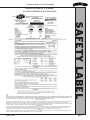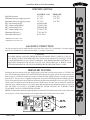
1
North Americas Best GRAND BAY 40 DIRECT VENT FREESTANDING GAS STOVE CAUTION! PRIOR TO FIRST FIRE: Clean gold door with a glass cleanser and soft cloth, as fingerprint oils will cause discoloration on gold when heated. INSTALLATION, OPERATION, VENTING AND MAINTENANCE INSTRUCTIONS WARNING If the information in this manual is not followed exactly a fire or explosion may result, causing property damage, personal injury or death. FOR YOUR SAFETY DO NOT store or use gasoline or other flammable vapors and liquids in the vicinity of this or any other appliance. WHAT TO DO IF YOU SMELL GAS Extinguish any open flame. Immediately call your gas supplier from a neighbors phone. Open windows. Follow the gas suppliers instructions. Do not try to light any appliance. If you cannot reach your gas supplier, call the fire department. Do not touch any electric switch. Installation and service must be performed by a qualified Do not use any telephone in your building. installer, service agency, or the gas supplier. WARNING Improper installation, adjustment, alteration, service or maintenance can cause injury or property damage. Refer to this manual for correct installation and operational procedures. For assistance or additional information consult a qualified installer, service agency, or the gas supplier. Part #250-3681 #842-2550 401 N. Wynne Street Colville, WA 99114 SAVE THESE INSTRUCTIONS Revised 1/2000 www.aladdinhearth.com [email protected] Grand Bay 40 Direct Vent Freestanding CONTENTS TABLE OF CONTENTS Page 2 PAGE Safety Label .......................................................................................................................... 3 Safety Notices ....................................................................................................................... 4 Specifications ....................................................................................................................... 5 Gas Line Connection ............................................................................................................ 5 Pressure Testing ................................................................................................................... 5 Dimensions ........................................................................................................................... 6 Listings ................................................................................................................................. 6 Clearances to Combustibles ................................................................................................. 7 Hearth Requirements ............................................................................................................ 7 High Altitude Operation ....................................................................................................... 8 Unpacking the Stove............................................................................................................. 8 Gas Valve Location .............................................................................................................. 8 Door Installation ................................................................................................................... 9 Brick Installation .................................................................................................................. 10 Brick retainer tab ........................................................................................................... 10 Log Set Installation .............................................................................................................. 11 Thermostat Installation ......................................................................................................... 12 Remote Control Wall Switch ................................................................................................. 12 Blower Power Cord .............................................................................................................. 12 Installation Procedures Gas Connections ............................................................................................................ 13 Venting Instructions ............................................................................................................. 14 Simpson Dura-Vent parts list ............................................................................................... 15 Basic kits ........................................................................................................................ 16 General Maintenance ............................................................................................................ 16 Venting ................................................................................................................................. 17 Planning Your Installation.................................................................................................... 18 Venting Graph ...................................................................................................................... 20 Venting Horizontal installation.................................................................................................... 21 Vertical terminations Using GS series pipe ...................................................................................................... 25 Cathedral ceiling installation ......................................................................................... 28 Installation into a Class A Metal Chimney .................................................................... 29 Installation into an Existing Masonry Chimney ............................................................ 30 Lighting Instructions ............................................................................................................ 33 First Fire ............................................................................................................................... 34 Maintenance Cleaning and inspection ................................................................................................. 35 Burner tube cleaning ...................................................................................................... 35 Glass cleaning ................................................................................................................ 35 Schematics ............................................................................................................................ 36 Blower and Snap Disc Replacement .................................................................................... 37 Troubleshooting .................................................................................................................... 38 Accessories & Replacement Parts ........................................................................................ 39 Warranty ............................................................................................................................... Back Cover Warranty Card ...................................................................................................................... Insert January 2000 Grand Bay 40 Direct Vent Freestanding GBDV-40 SAFETY LABEL (FOUND ON PEDESTAL ACCESS DOOR) Vented Gas Fireplace Heater 0-2000' 0-2000' #65 #63 #53 NOTE: In Canada, approved for altitudes 0-4500 ft. (0-1370m). In USA, this appliance equipped only for altitudes 0-2000 ft. (0-610m)./ REMARQUE: Au Canada, approve pour les altitudes de 0-4500Pi (0-1370m). Aux Etats-Unis, cet apparell est equipe seulement pour les altitudes de 0-2000Pi (0-610m). THISVENTED GAS FIREPLACE HEATER IS NOT FOR USE WITH AIR FILTERS./ CETTE FOURNAISE AU GAZ AVEC VENTILATION NE DOIT PAS ETRE UTILISEE AVEC DES FILTRES DAIR. THIS APPLIANCE IS ONLY FOR USE WITH THE TYPE OF GAS INDICATED ON THE RATING PLATE AND MAY BE INSTALLED IN AN AFTERMARKET, PERMANENTLY LOCATED, MANUFACTURED (MOBILE) HOME WHERE NOT PROHIBITED BY LOCAL CODES, SEE OWNERS MANUAL FOR DETAILS, THIS APPIANCE IS NOT CONVERTIBLE FOR USE WITH OTHER GASES, UNLESS A CERTIFIED KIT IS USED./CET APPAREIL DOIT ETRE UTILISE SEULEMENT AVEC LE TYPE DE GAZ LOCAUX LE PERMETTENT, LISEZ LE MANUEL DU PROPRIET AIRE POUR LES DETAILS SUPPLEMENTAIRES. CET APPAREIL NE DOIT PAS ETRE CONVERTI POUR LUSAGE AVEC DAUTRES GAZ A MOINS QUUNE TROUSSEE CERTIFIEE EST UTILISEE. CAUTION / ATTENTION Do not operate this appliance with glass removed, , cracked or broken. Replacement of the panel(s) should be done by a licensed or qualified service person./Ne pas operer cet apparellsl la vitre a ete enlevee, ou si elle est craquee ou brisee. Le remplacement dun panneau doiz etre effectue par une personne de service licensiee et qualiflee. Hote while in operation. Do not touch. Keep children, clothing, furniture, gasoline and other liquids having flammable vapors away./ Chaud lorsquen operation. Ne touchez pas. Gardez les enfants, les vetements, les meubles, la gazoline ou autres liquides de vapeur inflammable a une distance eloignee. WARNING / AVIS Operation of this appliance when not connected to a properly installed and maintained venting system or tampering witn the blocked vent shutoff system can result in carbon monoxide (CO) poisoning and possible death./Loperation de cet appareil, lorsqull nest pas connecte a un systeme de ventilation, installe et maintenu correctement, ou lalteration de iinterrupteur du systeme de ventilation peut resulter a un empolsonnement doxyde de carbone (CO) ou meme, dune perta de vle. WARNING: Improper installation, adjustment, alteration, service or maintenance can cause injury or property damage. Refer to the owhers manual provided with this appliance. For assistance or further information consult a qualified installer, service agency or the gas supplier. January 2000 SAFETY LABEL ANSIZ21.88-1998/CSA 2.33-M98 CAN/CGA 2.17-M91/UL307b Page 3 Grand Bay 40 Direct Vent Freestanding SAFETY NOTICES SAFETY NOTICES Page 4 This stove should be installed only by a qualified installer. It is approved for installation in a bedroom. Bedroom installation in Canada requires that the stove be connected to a thermostat. The stove must be electrically grounded in accordance with local codes, or the latest edition of the National Electric Code. If no local codes exist, this stove should be installed following the current codes: CAN/CGA-B149.1 ........................................................................ Natural Gas Installation Code CSA-C22.1 .................................................................................... Canadian Electrical Code ANSI Z223.1 ................................................................................. National Fuel Gas Code ANSI NFPA-70 ............................................................................. National Electrical Code Manufactured (mobile) home installation must conform to the manufactured home construction and safety standard (UL307B, Title 24 CFR, Part 3280), or when such a standard is not applicable, the standard for manufactured home installations (ANSI A225.1/NFPA 501A). The control compartment, burner, and circulating air passageways MUST be kept clean and clear to allow for adequate combustion and proper operation. Provide adequate clearances around air openings and adequate accessibility clearance for service and operation. NEVER obstruct the openings of the stove or the vent termination on the exterior of the building. NEVER vent the stove to other rooms or buildings; this stove must be vented ONLY to the outside. During installation, be sure to maintain minimum clearances to combustibles, as shown on page 7. Always contact your local building department or fire department prior to installing this stove. If required, obtain a permit before installing, and have the completed installation inspected. Failure to do this could jeopardize your homeowners insurance. The area around the stove MUST be kept free from combustible materials, gasoline and other flammable vapors and liquids. This stove is hot during operation, and should be located out of heavy traffic areas and away from furniture and draperies. Clothing or other flammable material should not be placed on or near the stove. Children and adults should be alerted to the hazards of high surface temperatures and should stay away to avoid burns or clothing ignition. Children should not be left unsupervised in the room when this stove is in operation. If any part of this stove has been under water, DO NOT USE it!! Immediately call a qualified service technician to inspect the stove, and to replace any part of the control system or any gas control which has been under water. This stove should NOT be modified under any circumstances. Any parts removed for servicing must be replaced before operating this stove. Installation and repair should only be done by a qualified service technician. The stove and its venting system should be inspected and cleaned annually by a qualified service technician. More frequent cleaning may be necessary due to excess lint and dust from carpeting, bedding material, etc. Be sure to turn off gas valve and pilot before cleaning this stove. Install at least one smoke detector on each floor of your home to ensure your safety. They should be located away from the gas stove and close to the sleeping areas. Follow the smoke detector manufacturers placement and installation instructions, and be sure to maintain regularly. Your local fire department may provide assistance in selecting smoke detectors, or contact the Consumer Product Safety Commission, Washington, D.C. 20207. WARNING: Do not operate appliance with the glass front removed, cracked or broken. Replacement of the glass should be done by a licensed or qualified service person. January 2000 Grand Bay 40 Direct Vent Freestanding SPECIFICATIONS PROPANE 10.0 WC 11 0 WC 14.0 WC *Minimum vent, blower off **Maximum vent, blower on GAS LINE CONNECTION Gas line connection can be made near the lower rear of the stove (3/8 gas hookup). You must supply a shutoff valve installed in a visible location within 3 (914mm) of the stove. CAUTION IN SOME AREAS, GAS LINE PRESSURE MAY BE MORE THAN 1/2 PSIG (14 WC). IF YOU BELIEVE THAT THIS MIGHT BE THE CASE IN YOUR LOCALITY, CONTACT YOUR GAS SUPPLIER OR LOCAL UTILITY COMPANY. LINE PRESSURE GREATER THAN 1/2 PSIG WILL DAMAGE THE STOVE VALVE. YOU MUST INSTALL A REGULATOR UPSTREAM FROM THE STOVE IF LINE PRESSURE IS GREATER THAN 1/2 PSIG. PRESSURE TESTING During any pressure testing of the gas supply piping system that exceeds test pressures of 1/2 PSIG, this stove and its individual shutoff valve must be disconnected from the piping system. If test pressure is less than or equal to 1/2 PSIG, then this stove must be isolated from the piping system by closing its individual shutoff valve. The gas valve is supplied with pressure test ports for checking input and output pressures. These are located just above the on/off knob and can be found inside the hinged lower access grill. The port on the left is for output pressure and the port on the right for input. Pressure can be checked by turning the captured screw counterclockwise two or three turns and then placing the manometer tubing over the test port. BE SURE TO CLOSE CAPTURED SCREWS AFTER TESTING BY TURNING THEM CLOCKWISE. DO NOT OVERTIGHTEN SCREWS. NOTE: To make flame and heat output adjustments, turn the HI-LO knob located on the center of the valve (as seen below). Turn counterclockwise for a higher flame and clockwise for a lower flame. ,13876,'( 7(679$/9( SPECIFICATIONS Manifold pressure Minimum inlet gas supply pressure Maximum inlet gas supply pressure BTU input rating (high) BTU output rating (high)* BTU input rating (low) BTU output rating (low)* Minimum efficiency* Maximum efficiency** NATURAL GAS 3.5 WC 4.5 WC 7.0 WC 40,000 40,000 33,400 33,600 28,000 28,000 23,380 23,520 77.6% 80.2% 83.5% 84% 2873876,'( 7(679$/9( January 2000 Page 5 Grand Bay 40 Direct Vent Freestanding DIMENSIONS PP DIMENSIONS PP PP PP PP PP PP PP PP PP GLDPHWHU'XUD9HQWSLSH PP PP LISTINGS The Quadra-Fire GBDV-40 is listed to ANSI Z21.88-1998/CSA 2.33-M98 CAN/CGA 2.17-M91/ UL307b, by OMNI-Test Laboratories, Inc., Beaverton, Oregon. Page 6 January 2000 Grand Bay 40 Direct Vent Freestanding CLEARANCES TO COMBUSTIBLES Minimum clearances to combustible materials from stove body: A B C D Side wall to combustible Back wall to combustible Top of unit Corner clearance 7"(178mm) 4" (102mm) 22" (559mm) 1" (25mm) CLEARANCES HEARTH REQUIREMENTS The floor area beneath the stove must be stable, level and strong enough to support the stove without a tipping hazard. Wood flooring, ceramic tile, brick hearths, or high pressure laminate flooring applied directly over the sub-flooring material meet this requirement. If the appliance is installed over carpet or combustible tile (vinyl tile), a metal or wood panel esxtending the full width and depth of the appliance must be installed. January 2000 Page 7 Grand Bay 40 Direct Vent Freestanding HIGH ALTITUDE OPERATION HIGH ALTITUDE In Canada, this unit is approved from 0 to 4500 feet above sea level. Installation of this stove at altitudes above 4500 feet is subject to field test of the individual installation and approval by the local authority having jurisdiction. Page 8 In the United States, input ratings of this unit are based on sea level operation, and shall not be changed for operation at elevations up to 2000 feet. For operation at elevations above 2000 feet, this stove shall be reduced at the rate of 4% for each 1000 feet above sea level. Exception: As permitted by the authority having jurisdiction. UNPACKING THE STOVE 1. 2. Unbolt pallet from stove using a 7/16 wrench to remove the two bolts from the underside of the pallet. Logs, twigs, brick refractory, touch-up paint and Owners Manual are packed in the firebox for security in shipping. GAS VALVE LOCATION 1. 2. Gas valve is located behind bottom grill. Bottom grill hinges down; stove controls will then be visible. %27720*5,// January 2000 Grand Bay 40 Direct Vent Freestanding DOOR INSTALLATION INSTRUCTIONS 5. 6. 7. 8. 9. 10. 11. 12. 13. Open side panels on stove. Open lower grill by carefully lowering it. Unscrew acorn nuts from hinge pins on door. Holding door horizontally, with inside of door facing up, insert hinge pins into hinge brackets located below the opening of the stove, and slide door as far as possible to the left. You may need to rock the door up and down slightly to fully insert the pins. Unwrap chains from door latches. Carefully close door. While holding the door closed, slide the bell on the end of each chain into the notch at the back edge of the stove side, directly behind the lower latch spring bolt (A). Replace acorn nuts on hinge pins, tightening until finger tight. Open each door latch. Insert the head of each latch bolt into V notch of door retention bracket. Holding latch bolt in place, fold door latch shut. You will need to adjust latch bolt until latch closes firmly, and springs are under tension when the latch is shut. Firmly bump the heel of your hand along the edges of the door frame, in order to ensure a complete seal of the door gasket. DO NOT USE A HAMMER OR ANY OTHER TOOL. DO NOT HIT THE GLASS. Inspect the door frame to make sure the gasket is completely sealed against the face of the stove. If gasket is not firmly sealed to face of stove, bump the door frame again until it seals. Carefully close side panels and grill. Remove all labels from glass, and clean all gold surfaces before burning stove (see page 35 of this manual for cleaning instructions). DOOR OPEN January 2000 Door Retention Chain in Place A Door Latch DOOR Latch Bolt DOOR LATCHED INSTALLATION: 1. 2. 3. 4. Page 9 Grand Bay 40 Direct Vent Freestanding INSTALLATION: BRICK BRICK INSTALLATION Page 10 The brick in this unit is packed in a separate box to prevent breakage during shipping. To install the brick, follow the directions below: 1. 2. 3. 4. 5. Place brick A on the lower bottom left side of the firebox at an angle, and tip the top edge up until it slides into the slots on the top of the firebox and behind the manifold block. Bend brick retainer tab down. Place brick B on the lower bottom right side of the firebox at an angle, and tip the top edge up until it slides into the slots on the top of the firebox. Bend brick retainer tab down. Place brick C on the left side of the firebox floor in front of the manifold block. Place brick D on the right side of the firebox floor so that the cutout slides around the log holder. Slide brick E in front of the front burner tube so that the brick fits between the burner tube and the face of the insert. Brick must be moved toward face of insert, and MUST NOT BLOCK front burner tube air shutter. Brick Retainer Brick A Brick Retainer Brick B Gas Manifold Brick C Gas Manifold Brick D Log Holder Brick E Front Log Support BRICK RETAINER TAB After left and right brick panels are installed, bend brick retainer tabs down (as shown below) to insure panels do not move from their correct locations. January 2000 Grand Bay 40 Direct Vent Freestanding CORRECT LOG PLACEMENT IS IMPORTANT TO PREVENT SOOTING! The vacuumformed ceramic logs are extremely fragile. PLEASE HANDLE CAREFULLY. Small chips on the logs can be covered up using the touch-up paint supplied with the stove.This appliance has been supplied with external shutter adjustments. Loosen the 3 shutter locking screws at left side of burners. (If this appliance is a Direct Vent this is not necessary) CENTERING PINS SHUTTER 1. Install rear log on log shelf ensuring that both log shelf and log are pressed firmly against back wall. 2. Install front log by positioning over centering pins and lowering. (Take care not to force and cause damage to molded holes in bottom of log.) CERAMIC 5. Light appliance and let logs cure for 30 minutes. Adjust shutters to give good flame characteristics. NOTE: If flame tips have dark yellow or black tips, shutters need to be opened. LOGS 3. Place right twig on front and rear log using ce4. Place ember nuggets across front of burner. ramic pins and placement holes in bottom of twig for alignment. (If ceramic pins are too close, tilt front log forward, do not make new holes in twigs.) Repeat step for left twig. INSTALLATION: INSTALLING THE LOG SET 6. After correct flame adjustment has been achieved, cool appliance, remove twigs and front log and tighten shutter adjustment screws. IMPORTANT: If shutter adjustment screws are not tightened, expansion and contraction of burner can allow shutter to close and cause sooting. January 2000 Page 11 INSTALLATION: THERMOSTAT Grand Bay 40 Direct Vent Freestanding THERMOSTAT INSTALLATION If desired, a thermostat may be installed to regulate the Quadra-Fire GBDV-40. It is important to use a thermostat designed for millivolt operation. Do not connect this stove to a thermostat serving any other appliance. OPTIONAL THERMOSTATS Manual Thermostat Part #812-2880 Anticipator Setting 1.2 Electronic Setback Part #811-0520 Thermostat Connection Block RECOMMENDED MAXIMUM LEAD Power Cord LENGTH (TWO WIRE) WHEN USING WALL THERMOSTAT/SWITCH Wire Size Maximum Length 16 gauge 65 feet 18 gauge 40 feet 20 gauge 25 feet 22 gauge 18 feet Page 12 Connect the thermostat wires to the two center screw terminals in the thermostat connection block, located at the lower rear of the unit. Turn off the manual switch, located on the control panel. REMOTE CONTROL A remote control or a wall switch may be wired to the thermostat terminals. Contact your QuadraFire dealer or service person for details (see page 39 for part number). BLOWER POWER CORD The blower cord is located at the rear of the stove, and needs to be routed to a three-prong outlet with correct polarity. Be sure that the stove is electrically grounded in accordance with local codes, with a current version of CSA C22 (in Canada), or in the absence of local codes, with the National Electric Code ANSI/NFPA 70-1987. WARNING Do not cut the grounding terminal off under any circumstances. Do not route the power cord under the body of the stove due to high temperatures. January 2000 Grand Bay 40 Direct Vent Freestanding INSTALLATION: CONNECTION INSTALLATION PROCEDURES The following procedures show some of the basic installation applications. Remember that every installation is different, and the installer should adjust to insure that the stove is installed properly. GAS CONNECTIONS Before hooking up the stove to the gas supply, be sure that the stove you are installing is designed for the type of gas being supplied to it. There is a serial number and listing label on the rear of the stove that will indicate which type of gas it is designed to utilize. The gas valve also has a label telling the type of fuel for which it is set up. There is a 3/8 gas hookup located under the stove body, with access from the rear through the pedestal cutout. We recommend connecting the stove with an approved flex gas line, as shown below. If flex gas lines are not approved in your area, you can connect a hard pipe to the gas hookup. GAS January 2000 Page 13 Grand Bay 40 Direct Vent Freestanding VENTING: INSTRUCTIONS VENTING INSTRUCTIONS PLEASE NOTE: In order to comply with applicable codes and product warranties, only Simpson Dura-Vent venting components may be used. DO NOT USE FIELD-FABRICATED VENTING COMPONENTS. The Quadra-Fire GBDV-40 is approved to be vented either through the side wall or vertically through the roof. You may vent through a Class A or masonry chimney if a Simpson Dura-Vent adapter is used (for USA installations only). Only Simpson Dura-Vent components labeled and listed in this section may be used. IMPORTANT Read all these instructions carefully before starting the installation. Failure to follow instructions may create a fire or other safety hazard, and will void the warranty. Be sure to follow these installation instructions for venting and clearance to combustible requirements, which may vary from one installation to another. Do not extend the venting system in excess of the distance prescribed in these manufacturers installation instructions. INSTALLATION PRECAUTIONS The Quadra-Fire GBDV-40 is an engineered product that has been designed and tested. The warranty will be voided, and serious fire, health, or other safety hazards may result from any of the following actions: installation of any damaged venting component, unauthorized modification of the venting system, installation of any component part not approved by Aladdin Hearth Products, or installation other than as instructed by these instructions. Consult your local building codes before beginning this installation. WARNING: Always maintain the required clearances (air space) to nearby combustibles to avoid creating a fire hazard. Do not fill air space with insulation. Minimum clearance between vent pipes and combustible surfaces is 1 (25mm), except where stated otherwise. Be sure to check the vent termination clearance requirements from decks, windows, soffits, gas regulators, air supply inlets and public walkways, as specified in these installation instructions and local building codes. (Refer to page 21 for horizontal installation instructions.) The gas stove and vent system must be vented directly to the outside of the building, and never be attached to a chimney serving a separate solid fuel or gas-burning appliance. This direct vent gas stove must use its own separate vent system. Common vent systems are prohibited. SAFETY PRECAUTIONS FOR THE INSTALLER Wear gloves and safety glasses for protection when installing this stove. Exercise extreme electrical caution when using ladders or on rooftops. Be aware of electrical wiring locations in walls and ceilings. Page 14 January 2000 Grand Bay 40 Direct Vent Freestanding SIMPSON DURA-VENT PARTS LIST January 2000 PARTS LIST NUMBER DESCRIPTION 705C Flashing (masonry chimney) 902 48 Pipe Length 902B 48 Pipe Length, Black 903 36 Pipe Length 903B 36 Pipe Length, Black 904 24 Pipe Length 904B 24 Pipe Length, Black 906 12 Pipe Length 906B 12 Pipe Length, Black 907B 9 Pipe Length, Black 908B 6 Pipe Length, Black 909B Retro Connector 911B 11 - 14 5/8 Pipe, Adjustable, Black 940 Round Support Box/Wall Thimble 941 Cathedral Ceiling Support Box 943 Flashing, 0/12 to 6/12 Roof Pitch 943S Flashing, 7/12 to 12/12 Roof Pitch 945 45° Elbow 945B 45° Elbow, Black 950 Vinyl Siding Standoff 953 Storm Collar 963 Ceiling Firestop 980 Standard Cap with Wind Guard 981 Snorkel Termination (36) 982 Snorkel Termination (14) 984 Horizontal Square Termination 985 High Wind Horizontal Termination Cap 985K Top Adapter 986K Top Adapter 987K Top Adapter 988 Wall Strap 990 90° Elbow 990B 90° Elbow, Black 991 High Wind Vertical Termination Cap The following high wind horizontal termination cap may be obtained from your local dealer: HHW2 Hearth Technologies Inc. High Wind Horizontal Termination Cap VENTING: Simpson Dura-Vent offers a complete line of component parts for installation in both horizontal and vertical applications. Many items are offered in decorative black, as well as galvanized finish. The galvanized pipe and fittings are used for concealed locations such as attics, or spaces where corrosion is a factor, such as above the roofline. Decorative brass and chrome trim kits are available for both wall thimbles and ceiling support boxes. Snorkel terminations are available for applications which may require a vertical rise on the building exterior. The following components have been approved for use with the Quadra-Fire GBDV-40: Page 15 Grand Bay 40 Direct Vent Freestanding SIMPSON DURA-VENT PARTS LIST (cont.) VENTING: PARTS KITS BASIC KITS Page 16 The standard termination kit (Kit 970) includes the following: 990B 1 each 90° Black Elbow 940 1 each Round Ceiling Support/Wall Thimble 984 1 each Horizontal Square Cap NOTE: The above kit is not a complete termination system. You will need to order the straight pipe lengths needed to complete the installation. The black 45° elbow is not included in this kit. The standard termination kit (Kit A971) includes the following: 990B 1 each 90° Black Elbow 940 1 each Round Ceiling Support/Wall Thimble 984 1 each Horizontal Square Cap 904B 1 each 24 Black Pipe 911 B 1 each 11 - 14 5/8 Black Adjustable Pipe The vertical termination kit (Kit 973) includes the following: 943 1 each Flashing 0/12 - 6/12 953 1 each Storm Collar 991 1 each Vertical Termination Cap NOTE: The support box is not included in this kit. GENERAL MAINTENANCE Conduct an inspection of the venting system twice a year. Recommended areas to inspect are as follows: 1 . Check areas of the venting system which are exposed to the elements for corrosion. These will appear as rust spots or streaks and in extreme cases, holes. These components should immediately be replaced. 2. Remove the cap, and shine a flashlight down the vent. Remove any bird nests, or other foreign material. 3. Check for evidence of excessive condensation, such as water droplets forming in the inner liner and subsequently dripping out at joints. Continuous condensation can cause caps, pipe and fittings to corrode. Condensation can be caused by having excessive lateral runs, or too many elbows. 4. Inspect joints to verify that no pipe sections or fittings have been disturbed and consequently loosened. Also check mechanical support such as wall straps, or plumbers tape for rigidity. January 2000 Grand Bay 40 Direct Vent Freestanding VENTING A B D E F G H I J K L M N Clearance to non-mechanical air supply inlet to building, or the combustion air inlet to any other stove - 12 (305mm) minimum Clearance above paved sidewalk or a paved driveway located on public property - 84 (2.1m) minimum Not to be installed above a meter/regulator assembly within 36 (914mm) horizontally from the centerline of the regulator Clearance to service regulator vent outlet - 72 (1.8m) minimum Clearance above grades, veranda, porch, deck or balcony - 12 (305mm) minimum Clearance to window or door that may be opened - 12 (305mm) minimum on top and sides and 24 below Clearance to permanently closed window - 12 (305mm) recommended to prevent condensation on window Clearance under veranda, porch, deck or balcony - 18 (457mm) minimum if fully open on a minimum two sides beneath the floor Vertical clearance to ventilated soffit located above the terminal within a horizontal distance of 24 (610mm) from the centerline of the terminal - 18 (457mm) minimum Clearance to unventilated soffit - 12 (305mm) minimum Clearance to inside corner - 9 (229mm) minimum Clearance to a mechanical air supply inlet - 72 (1.8m) minimum Clearance to outside corner - 6 (152mm) minimum H January 2000 CLEARANCES A vent shall not terminate directly above a sidewalk or paved driveway which is located between two single family dwelling and serves both dwellings (not pictured). A vent shall not terminate within 36" (914mm) of the property line (not pictured). For USA installations follow current National Fuel Gas Code ANSI Z223.1. VENTING: NOTE: This stove is a direct vent heater. All combustion air must come directly from the outside of the building. Vent pipe for this unit consists of an inner and an outer layer. The inner layer carries the stove exhaust out of the system, and the outer layer brings fresh combustion air into the stove. Page 17 Grand Bay 40 Direct Vent Freestanding There are four types of direct vent system installations approved for use with the GBDV-40. It is very important to maintain a balance between the combustion air intake and the flue gas exhaust venting system. The types of installation are: Horizontal Termination (Figure 1) Vertical Termination (Figure 2) Into a Class A Metal Chimney (Figure 3)* Into a Masonry Chimney (Figure 4)* *USA installations only Note: Certain limitations as to vent and vertical termination configuration apply, and must be strictly adhered to. When planning your installation, it will be necessary to select the proper length of vent pipe for your particular requirements. The vent graph on page 20 will show the relationship between vertical and horizontal side wall venting, and will help to determine the various vent lengths permitted. It is also important to note the wall thickness. Select the amount of vertical rise desired for vertical-to-horizontal type installations. To determine the length of your pipe required for vertical installations, measure the distance from the application flue outlet to the ceiling, the ceiling thickness, the vertical rise in an attic or second story, and allow for sufficient vent height above the roofline. For two-story applications, fire stops are required at each floor level. If an offset is needed in the attic, additional pipe and elbows will be required. VENTING: INSTALLATION PLANNING YOUR INSTALLATION When installing this appliance into an existing masonry chimney, it is important to carefully measure the length of flex needed to reach from the appliance outlet to the termination cap. If the flex length is too short, a flex coupler will be needed to attach an additional length of flex liner to make up the difference. If the flex length is too long, the liner could sag below the appliance outlet, which could result in a potential fire hazard. Page 18 January 2000 Grand Bay 40 Direct Vent Freestanding DuraVent # 985 DuraVent #991 9(57,&$/7(50,1$7,21 or HTI #HHW2 67250&2//$5 (/%2: +25,=217$/ 7(50,1$7,21 ),5(6723 :$//7+,0%/( 6833257%2; 3,3(/(1*7+ 3,3(/(1*7+ 3,3(/(1*7+ $33/,$1&($'$37(5 ,1&/8'(':6729( 3,3(/(1*7+ $33/,$1&($'$37(5 FIG. 2 FIG. 1 HIGH WIND TERMINATION CAP DuraVent #991 TERMINATION CAP TOP ADAPTER TOP ADAPTER VENTING: )/$6+,1* 3,3(/(1*7+ FLASHING EXISTING METAL CHIMNEY SYSTEM 4 FLEX LINER TYPES 4 FLEX PIPE RETRO CONNECTOR RETRO CONNECTOR DIRECT VENT PIPE DIRECT VENT PIPE FIG. 3 (USA installations only) January 2000 FIG. 4 (USA installations only) Page 19 Grand Bay 40 Direct Vent Freestanding HOW TO USE VENT GRAPH 1. Measure the distance from the top of stove to the center of the 90° elbow. On the graph below, draw a horizontal line from that measurement on the vertical axis across until it intersects with the slanted line. 2. From the point of this intersection, draw a vertical line to the bottom of the graph. 3. The point at which this line meets the bottom line of the graph is the maximum length of the horizontal run. Example 1: If the vertical dimension from the top of the stove to the center of the 90° elbow is 7 (2.13m), the horizontal run to the outer wall flange must not exceed 9 9 (2.97m). Example 2: If the vertical dimension from the top of the stove is 21 (6.4m), the horizontal run to the outer wall flange must not exceed 7 3 (2.21m). Note: The maximum horizontal vent run is 15 (4.57m) when the vertical vent rise is 10 (3.05m). The minimum horizontal vent run is 11 (279mm). Minimum wall thickness is 4 (102mm). Maximum wall thickness is 20 (508mm). VENTING: VENT GRAPH The following chart is used to determine the allowable distance of horizontal run for the amount of vertical rise. Page 20 January 2000 Grand Bay 40 Direct Vent Freestanding HORIZONTAL INSTALLATION VENTING: Step 1. Set the gas stove in its desired location. Check to determine if wall studs or roof rafters are in the way when the venting system is attached. If this is the case, you may want to adjust the location of the stove. Step 2. Simpson Dura-Vent pipe is designed with special twist-lock connections. To connect the venting system to the stove flue outlet, a twist-lock adapter is built into the stove at the factory. Assemble the desired combination of pipe and elbows to the adapter with pipe seams oriented towards the wall or floor, as much out of view as possible. Remember to include wall thickness in minimum clearances when figuring the measurements for your installation needs. Note: Twist-lock procedure: Four indentations, located on the female ends of pipes and fittings, are designed to slide straight onto the male ends of adjacent pipes and fittings by orienting the four pipe indentations so they match and slide into the four entry slots on the male ends (Figure 5). Push the pipe sections completely together, then twist-lock one section clockwise approximately one-quarter turn, until the two sections are fully locked. The female locking lugs will not be visible from the outside, on the pipe or fittings. They may be located by examining the inside of the female ends. FIG. 5 FEMALE LOCKING LUGS HORIZONTAL INSTALLATION MALE LOCKING LUGS NOTE: Horizontal runs of vent must be supported every 3 (914mm). Wall straps are available for this purpose. January 2000 Page 21 Grand Bay 40 Direct Vent Freestanding INSTALLATION VENTING: HORIZONTAL HORIZONTAL INSTALLATION (cont.) Step 3. With the adapter and pipe attached to the stove, slide the stove into its correct location, maintaining minimum clearance to combustibles, and mark the wall for a 10 x 10 (254mm x 254mm) square hole. The center of the square hole should line up with the centerline of the horizontal pipe, as shown in Figure 6. Cut and frame the hole in the exterior wall where the vent will be terminated. If the wall being penetrated is constructed of noncombustible material, i.e. masonry block or concrete, a 7 (178mm) diameter hole is acceptable. &(17(52)+2/( &(17(5 /,1( &(17(5/,1( FIG. 6 NOTE: (1) The horizontal run of vent must be level, or have a ¼ (6mm) rise for every 1 (305mm) of run towards the termination. Never allow the vent to run downward. This could cause high temperatures and may present the possibility of a fire. (2) The location of the horizontal vent termination on an exterior wall must meet all local and national building codes, and must not be easily blocked or obstructed. (3) For installations requiring a vertical rise on the exterior of the building, 14 (356mm) and 36 (914mm) tall snorkel terminations are available. Follow the same installation procedures as used for standard horizontal terminations. If the snorkel termination must be installed below grade (i.e. basement application), proper drainage must be provided to prevent water from entering the snorkel termination. Do not backfill around snorkel termination. NOTE: Only one 90° elbow is permitted per side wall (horizontal) installation. An additional 45° elbow is permitted for corner installations. Page 22 January 2000 Grand Bay 40 Direct Vent Freestanding HORIZONTAL INSTALLATION (cont.) VENTING: Step 4. Position the horizontal vent termination in the center of the 10 (254mm) square hole, and attach to the exterior wall with the four wood screws provided. Before attaching the Vent Termination to the exterior wall, run a bead of non-hardening mastic around its outside edges, so as to make a seal between it and the wall. The arrow on the vent cap should be pointing up. Insure that proper clearances to combustible materials are maintained (Figure 7). FIG. 7 NOTE: (1) The four wood screws provided should be replaced with appropriate fasteners to stucco, brick, concrete, or other types of sidings. (2) January 2000 HORIZONTAL FIG. 8 INSTALLATION For buildings with vinyl siding, a vinyl siding standoff (Simpson Dura-Vent part 950), should be installed between the vent cap and the exterior wall (Figure 8). Attach the vinyl siding standoff to the horizontal vent termination. The vinyl siding standoff prevents excessive heat from possibly melting the vinyl siding material. Vent terminal shall not be recessed into a wall or siding. Page 23 Grand Bay 40 Direct Vent Freestanding INSTALLATION HORIZONTAL HORIZONTAL INSTALLATION (cont.) Step 5. Before connecting the horizontal run of vent pipe to the vent termination, slide the black decorative wall thimble cover over the vent pipe. Step 6. Slide the stove and vent assembly towards the wall, carefully inserting the vent pipe into the vent cap assembly. It is important that the vent pipe extend into the vent cap sufficient distance so as to result in a minimum pipe overlap of 1¼ (32mm). Secure the connection between the vent pipe and the vent cap by attaching the two sheet metal strips extending from the vent cap assembly into the outer wall of the vent pipe. Use the two sheet metal screws provided to connect the strips to the pipe section. Bend any remaining portion of the sheet metal strip back towards the vent cap, so it will be concealed by the decorative wall thimble cover (Figure 9). Note: The attachment from the vent pipe to the vent cap must be siliconed. VENTING: FIG. 9 Page 24 Step 7. Slide the decorative wall thimble up to the wall surface and attach with screws provided. Apply decorative brass or chrome trim if desired (Figure 10). FIG. 10 January 2000 Grand Bay 40 Direct Vent Freestanding VERTICAL TERMINATIONS USING GS SERIES PIPE VENTING: Step 1. Check the installation instructions for required clearances (air space) to combustibles when passing through ceilings, walls, roofs, enclosures, attic rafters, or other nearby combustible surfaces. Do not pack air space with insulation. Check the instructions for maximum vertical rise of the venting system, and any maximum horizontal offset limitations (Figure 11). All offsets fall within the set parameters of the vent graph located on page 20. NOTE: Maximum vertical rise allowable is 30 (9144mm) (Figure 11). NOTE: Maximum number of 45° elbows permitted for a vertical installation is four (4). Does not decrease maximum vertical rise. DuraVent #991 FIG. 11 P 0$;,080 FIG. 12 FIG. 13 January 2000 VERTICAL Step 3. To install the round support box/wall thimble in a flat ceiling, cut a 10 (254mm) square hole in the ceiling, centered on the hole drilled in Step 2. Frame the hole as shown in Figure 13. TERMINATIONS Step 2. Set the gas stove in its desired location. Drop a plumb bob down from the ceiling to the position of the stove flue exit, and mark the location where the vent will penetrate the ceiling. Drill a small hole at this point. Next, drop a plumb bob from the roof to the hole previously drilled in the ceiling, and mark the spot where the vent will penetrate the roof. Determine if ceiling joists, roof rafters, or other framing will obstruct the venting system. You may wish to relocate the stove, or to offset, as shown in Figure 12, to avoid cutting loadbearing members. Page 25 Grand Bay 40 Direct Vent Freestanding TERMINATIONS VERTICAL VERTICAL TERMINATIONS (cont.) USING GS SERIES PIPE (cont.) Step 4. Assemble the desired lengths of black pipe and elbows necessary to reach from the stove up through the round support box. Insure that all pipe and elbow connections are in their fully twist-locked position. Be sure to seal the pipe with appropriate sealant. Step 5. Cut a hole in the roof centered on the small drill hole placed in the roof in step 2. The hole should be of sufficient size to meet the minimum requirements for clearance to combustibles, as specified. Continue to assemble lengths of pipe and elbows necessary to reach from the ceiling support box up through the roof line. Galvanized pipe and elbows may be utilized in the attic, as well as above the roofline. The galvanized finish is desirable above the roofline, due to its higher corrosion resistance. NOTE: (1) If an offset is necessary in the attic to avoid obstructions, it is important to support the vent pipe every 3 (914mm) to avoid excessive stress on the elbows, and possible separation. Wall straps are available for this purpose (Figure 12). VENTING: (2) Page 26 Whenever possible, use 45° elbows, instead of 90° elbows. The 45° elbow offers less restriction to the flow of flue gases and intake air. Step 6. Slip the flashing over the pipe section(s) protruding through the roof. Secure the base of the flashing to the roof with roofing nails. Insure the roofing material overlaps the top edge of the flashing to the roof with roofing nails. Insure the roofing material overlaps the top edge of the flashing as shown in Figure 14. Verify that you have at least the minimum clearance to combustibles at the roofline. FIG. 14 January 2000 Grand Bay 40 Direct Vent Freestanding VERTICAL TERMINATIONS (cont.) USING GS SERIES PIPE (cont.) Step 8. Twist-lock the vent cap and seal. NOTE: (1) For multistory vertical installations, a ceiling firestop (SDV part #963) is required at the second floor, and any subsequent floors (Figure 16). The opening should be framed to 10 x 10 (254mm x 254mm) inside dimensions, in the same manner as shown in Figure 13. (2) Any occupied areas above the first floor, including closets and storage spaces, which the vertical vent passed through must be enclosed. The enclosure may be framed and sheetrocked with standard construction materials; however, refer to these installation instructions for the minimum allowable clearance between the outside of the vent pipe and the combustible surfaces of the enclosure. Do not fill any of the required air space with insulation. DuraVent #991 January 2000 VERTICAL FIG. 15 TERMINATIONS FIG. 16 VENTING: Step 7. Continue to assemble pipe sections until the height of the vent cap (H) (Figure 15) meets the minimum code requirements described in code requirements as outlined in the current CAN/CGA-Bl49 Installation Codes (in Canada), the National Fuel Gas Code NFPA 54/ ANSI Z223.1 (in USA), or local codes. Note that for steep roof pitches, the vent height must be increased. In high wind conditions, nearby trees adjoining rooflines, steep pitched roofs, and other similar factors can result in poor draft, or down drafting. In these cases increasing the vent height may solve this problem. Page 27 Grand Bay 40 Direct Vent Freestanding VERTICAL TERMINATIONS (cont.) CATHEDRAL CEILING INSTALLATION CEILING VENTING: CATHEDRAL Step 1. Follow installation Steps 1 and 2 under vertical termination section. Step 2. Using the plumb-bob, mark the centerline of the venting system on the ceiling, and drill a small hole through the ceiling and roof at this point. From the roof, locate the drill hole and mark the outline of the cathedral ceiling support box. Step 3. Remove shingles or other roof covering as necessary to cut the rectangular hole for the support box. Cut the hole 1/8" (3mm) larger than the support box outline. Step 4. Lower the support box through the hole in the roof until the bottom of the box protrudes at least 2 (51mm) below the ceiling (Figure 18). Align the support box both vertically and horizontally with a level. Temporarily tack the support box in place through the inside walls and into the roof sheathing. FIG. 18 Step 5. Using tin snips, cut the support box from the top corners down to the roofline, and fold the resulting flaps over the roof sheathing (Figure 19). Before nailing it to the roof, run a bead of non-hardening mastic around the top edges of the support box to make a seal between it and the roof. Clean out any combustible material from inside the support box. FIG. 19 Step 6. Complete the cathedral ceiling installation by following the same procedures outlines in steps 4 through 8 for vertical terminations. Page 28 January 2000 Grand Bay 40 Direct Vent Freestanding VERTICAL TERMINATIONS (cont.) VENTING: INSTALLATION INTO A CLASS A METAL CHIMNEY NOTE: Have the existing installation inspected by a qualified chimney sweep or professional installer prior to converting to direct vent. The existing chimney system must be in serviceable condition and functionally sound. Step 1. Remove existing chimney cap. Step 2. Measure the distance from the top of the chimney to the bottom of the ceiling support box, add 3 (76mm) to this measurement, and cut a section of 4 (102mm) flex pipe to that length (the flex should be extended to its nominal length). Step 3. Connect the end of the flex pipe section to the underside of the top adapter (SDV #985K, 986K or 987K), using three sheet metal screws (Figure 20). Step 4. Pass the flex pipe down through the center of the chimney system, and center the top adapter on the top of the chimney pipe. Drill four 1/8 (3.3mm) diameter holes through the top adapter, and into the chimney top. Insure that you are drilling into the metal on the chimney. Twist lock the high wind termination cap (SDV #991) onto the top adapter (Figures 21 and 22). Step 5. Pull the flex pipe down through the ceiling support box, until it protrudes approximately 3 (76mm). Connect the flex pipe to the retro connector (SDV #909B), and attach with sheet metal screws. Step 6. Push the flex pipe back up into the ceiling support box, center the retro connector, and attach it to the support box with sheet metal screws. FIG. 21 FIG. 22 SHEET METAL SCREWS January 2000 CLASS A FIG. 20 METAL CHIMNEY Step 7. The connection between the appliance and the retro connector may be completed with sections of direct vent pipe. Page 29 MASONRY CHIMNEY VENTING: EXISTING Grand Bay 40 Direct Vent Freestanding Page 30 VERTICAL TERMINATIONS (cont.) INSTALLATION INTO AN EXISTING MASONRY CHIMNEY Step 1. Before cutting any holes, assemble the desired sections of direct vent pipe to determine the center of the masonry penetration. FIG. 23 Step 2. Once the center point of the penetration has been determined, cut a 6 (152mm) diameter hole in the masonry. If the hole is too large, the retro connector might not mount properly; if the hole is too small, the appliance might starve for intake air. If there is a frame wall in front of the masonry wall, cut and frame a 10 (254mm) square opening in the wall (centered around the 6 [152mm] masonry opening). If there is sheet rock only (no studs) in front of the masonry the 10 (254mm) opening is still needed, but does not need to be framed. This allows the retro connector to mount directly on the masonry and provide the correct clearances to combustibles (see Figure 23). Step 3. Secure the flashing (SDV #705C) to the top of the masonry chimney using a bead of non-hardening sealant-adhesive. If the flashing is larger than the top of the chimney, cut and fold flashing as needed to fit chimney (Figure 24). Step 4. To determine the length of flex needed, measure from 3 (76mm) above the top of the flashing down to the level of the opening. Add the distance from the center of the chimney out through the wall. Cut a piece of 4 (102mm) flex to this length (extended to its nominal length). Be sure to leave 2-3 (51mm76mm) of flex above the existing chimney to allow for connection to the termination kit. FIG. 24 January 2000 Grand Bay 40 Direct Vent Freestanding VERTICAL TERMINATIONS (cont.) Step 5. Connect the flex liner to the top adapter using three sheet metal screws (see Figure 20). Step 6. Feed the flex liner through the flashing into the chimney. Carefully feed the flex liner down the chimney to the bottom and out the opening in the masonry wall, forming an angle to line up the flex liner with the vent opening on the appliance. NOTE: Do not let the flex liner sag below the level at which it will connect to the appliance or connector. This could allow hot gas to become trapped and potentially become a fire hazard. The flex liner path should always be sloped up toward the termination cap. Step 8. Secure the top adapter to the flashing. Use three sheet metal screws through the side of the top adapter into the flange on the flashing (Figure 26). Twist lock the high wind termination cap (SDV #991) on to the top adapter. EXISTING Step 7. If additional lengths of flex liner are needed to span the chimney height, use a flex coupler to connect the pieces of flex liner together. Connect the flex to the coupler by using four sheet metal screws for each side (Figure 25). MASONRY CHIMNEY TOP ADAPTER FIG. 25 VENTING: INSTALLATION INTO AN EXISTING MASONRY CHIMNEY (cont.) FIG. 26 January 2000 Page 31 MASONRY CHIMNEY VERTICAL TERMINATIONS (cont.) INSTALLATION INTO AN EXISTING MASONRY CHIMNEY (cont.) VENTING: EXISTING Grand Bay 40 Direct Vent Freestanding Page 32 Step 9. Attach the flex to the retro connector. Use three sheet metal screws to attach the flex liner to the connector (Figure 27). Mount the retro connector to the masonry wall using masonry bolts. Redrill larger holes on connector as needed. Be careful to insure that the connector is centered in the opening and the mounting holes line up with the masonry wall. Step 10. Slide wall thimble cover (SDV #940) over retro connector and secure with masonry bolts (Figure 28). If you have a framed wall in front of the masonry, use wood screws to mount wall thimble cover to framed wall, over retro connector and 10 (254mm) square framed opening (Figure 23, page 30). If needed, add a section of direct vent pipe to the retro connector in order to extend through the opening in the wall thimble cover. FIG. 27 Step 11. The connection between the appliance and the retro connector may be completed with sections of direct vent pipe. Step 12. Move the appliance into the desired location. FIG. 28 January 2000 Grand Bay 40 Direct Vent Freestanding LIGHTING INSTRUCTIONS (LOCATED BEHIND PEDESTAL ACCESS DOOR) FOR YOUR SAFETY READ BEFORE LIGHTING A. 1. 2. 3. 4. 5. 6. 7. 8. 9. 10. 11. LIGHTING This appliance has a pilot that must be lit by hand. When lighting the pilot, follow these instructions exactly. B. BEFORE LIGHTING, smell all around the appliance area for gas. Be sure to smell next to the floor because some gas is heavier than air and will settle on the floor. WHAT TO DO IF YOU SMELL GAS: · Do not try to light any appliance. · Do not touch any electric switch; do not use any phone in your building. · Immediately call your gas supplier from a neighbors phone. Follow the gas suppliers instructions. · If you cannot reach your gas supplier, call the fire department. C. Use only your hand to push in or turn the gas control knob. Never use tools. If the knob will not push in or turn by hand, dont try to repair it. Call a qualified service technician. Force or attempted repair may result in a fire or explosion. D. Do not use this appliance if any part has been under water. Immediately call a qualified service technician to inspect the appliance and to replace any part of the control system and any gas control that has been under water. LIGHTING INSTRUCTIONS STOP! Read the safety information prior to this section. If using a thermostat, set the thermostat to the lowest setting. Pull down the grill on appliance front to expose the control panel, and turn the ON/OFF switch to OFF. Turn off all electric power to the appliance. Open glass front. Push in gas control knob slightly and turn clockwise to OFF. NOTE: Knob cannot be turned from PILOT to OFF unless knob is pushed in slightly. Do not force. Wait five (5) minutes to clear out any gas. Then smell for gas including near the floor. If you smell gas, STOP! Follow B of the safety information in the section prior to this. If you dont smell gas, go to the next step. Turn knob on gas control counterclockwise to PILOT. Push in control knob all the way and hold in. Immediately light the pilot by repeatedly depressing the piezo igniter until a flame appears. NOTE: The pilot should be visible through the door glass in the lower left hand corner between the front and rear logs. As piezo igniter is depressed a blue spark can be seen. When lit, the flame will be visible. Continue to hold the control knob in for about thirty (30) seconds after the pilot is lit. Release knob and it will pop back up. Pilot should remain lit. If it goes out, repeat steps 5 through 8. · If the knob does not pop up when released, stop and immediately call your service technician or gas supplier. · If the pilot will not stay lit after several tries, turn the gas control knob to OFF and call your service technician or gas supplier. Close glass front. Turn gas control knob counterclockwise to ON. If you are not using a thermostat, turn ON/OFF switch to ON. If you are using a thermostat, leave the switch in the OFF position and set thermostat to desired setting. TO TURN OFF GAS TO APPLIANCE 1. 2. 3. 4. 5. If using a thermostat, set it to lowest setting. Turn off all electric power to the appliance if service is to be performed. Pull down grill on front of appliance to expose control panel. Push in gas control knob slightly and turn clockwise to OFF. Do not force. Close grill. January 2000 Page 33 Grand Bay 40 Direct Vent Freestanding FIRST FIRE FIRST FIRE NOTE: Never operate this stove with the door open. NOTE: No electrical power supply is required for the gas control to operate. Standing pilot allows the valve to operate with manual switch or millivolt thermostat. WARNING: When the stove is equipped with a 24 karat gold-plated door, you must clean all the fingerprints and oils from the gold surface before firing the stove for the first time. Use a glass cleaner or vinegar and a towel to ensure that the oil is removed. If not cleaned properly before firing, fingerprints or oil can cause permanent markings on the gold plating. After the gold plating is cured, the oils will not affect the finish and little maintenance is required; just wipe clean as needed. Before first firing the stove, read the owners manual to be familiar with the stoves features, controls, and cautions for operation. Remove all labels from glass before operating this stove for the first time. Plug power cord into a properly installed outlet for blower operation. The blower system has an on/off thermally operated snap disc that will turn the blower on automatically when the proper temperature is reached, and will turn the blower off when it cools down in order not to blow cool air after shut down. The blower speed control is located behind the lower grill. Manual on/off switch for control valve is located on the grill. Follow the lighting instructions on page 33 of manual, or metal lighting instructions located in lower pedestal access door. During your first fire in the stove, you may notice an odor and steam coming from the stove. This is normal. This is the high temperature paint finishing the curing process. Open the door and/or windows in the home or structure for ventilation. We recommend that you initially cycle the stove on and off, heating the stove to curing stage for several minutes, and then turn it off to cool for five minutes. Then turn the stove back on, and burn until the steam and/or odor no longer appears. If odor persists, turn the gas supply to the stove off, and call your local dealer or authorized service person to inspect the stove. Page 34 January 2000 Grand Bay 40 Direct Vent Freestanding MAINTENANCE CLEANING AND INSPECTION At least once yearly, preferably before the heating season, have the insert and venting system cleaned and inspected by a qualified service person. This will ensure proper and safe operation throughout the year. GLASS CLEANING WARNING: DO NOT CLEAN GLASS WHEN HOT. 1. 2. Turn off pilot. Open hinged side doors and unlatch spring latches. WARNING: DO NOT USE ABRASIVE CLEANERS ON GLASS OR GOLD SURFACES. 3. 4. 5. MAINTENANCE CLEANING THE BURNER TUBES 1. Turn off pilot light. 2. Open hinged side door and unlatch spring latch. 3. Remove logs and glowing charcoals. 4. Vacuum burner compartment, especially around orifice and primary air openings. 5. Relight pilot. Check to ensure flames are touching millivolt generator (see diagram at right). 6. Reinstall logs. See page 11 for log installation instructions. 7. Close front door and lock it in place with the allen screw. 8. Recheck pilot and main burner to insure they are operating correctly. Using regular glass cleaner, spray the glass surface and wipe with soft cloth or clean paper towel until surface is dry. Close door and tighten allen screw to prevent opening of the door while in operation. Relight pilot and check main burners operation. NOTE: If you observe a white film on the door glass, use a hard water deposit glass cleaner or contact your dealer. NOTE: Do not use abrasive materials or chemical cleaners. January 2000 Page 35 Grand Bay 40 Direct Vent Freestanding SCHEMATICS SCHEMATICS Page 36 January 2000 Grand Bay 40 Direct Vent Freestanding NOTE: BLOWER DOES NOT REQUIRE LUBRICATION. HOWEVER, WE RECOMMEND VACUUMING OR BRUSHING OFF DUST OR LINT FROM THE FAN BLADES AS NEEDED. This stove is equipped with a 160 cfm convection blower that is automatically controlled by a temperature-sensing snap disc (160º). The blower has a speed control located on the control panel in the front of the stove. The blower is located in the pedestal. To replace or access the blower, follow the instructions below. 1. Disconnect power from the unit and turn off gas supply. 2. Blower can be accessed either through the pedestal door in the front of the stove, or through the rear of the stove, as shown. 3. Remove screws fastening blower to stove body. 4. Lower blower away from stove. 5. Replace in reverse order. The snap disc can be accessed through the left side of the stove, as shown. To replace the snap disc: 1. Disconnect power from the unit and turn off gas supply. 2. Open side door to access snap disc. 3. Remove all wires attached to snap disc. 4. Remove set screw holding snap disc in place. 5. Slide snap disc up and out of holder. 6. Replace in reverse order. SNAP DISC LOCATION BLOWER LOCATION 61$3',6& 32:(5&25' %/2:(5 5($52)6729( BLOWER/SNAP DISC BLOWER AND SNAP DISC REPLACEMENT IMPORTANT! The blower is equipped with a three prong (grounding) plug for your protection against shock hazard, and should be plugged directly into a properly grounded three prong receptacle. Do not cut or remove the grounding prong from this plug. January 2000 Page 37 TROUBLESHOOTING Grand Bay 40 Direct Vent Freestanding TROUBLESHOOTING A. Pilot wont light 1. Make sure valve setting is in the pilot position. 2. Check for spark at igniter. a. If no spark: 1. Check the wiring between the piezo and the igniter. If bad, fix wiring; if good, you may have a faulty piezo or cracked ceramic on the electrode. 2. Call your Quadra-Fire dealer. b. If there is a spark: 1. Try to light the insert with a match. The flame should either light or flutter. a. If the flame flutters but does not light the pilot, there probably is air in the line. Hold flame to pilot hood, then bleed the line until gas comes through. b. If the match flame does not flutter, make sure the gas is turned on and be sure you are pushing the knob in all the way. If this still doesnt help, you may be dealing with a bad valve, a blocked pilot orifice, or a kinked pilot line. 3. Call your dealer or authorized service person. B. Pilot goes out when knob is released 1. Wait five minutes and try again. If the pilot still goes out, try again and hold the knob in longer. 2. If the problem persists, call your dealer or authorized service person. C. Pilot lights but burner wont ignite 1. Make sure the knob is turned to the on position. 2. Turn the thermostat up. 3. If there is no thermostat, flip the manual switch on the control panel of the stove. If the burner does not light, short out the thermostat screws on the face of valve marked TH and TPTH. If the burner lights, you may have a problem in the wiring of the stove, and it should be checked. 4. Check the thermostat and thermopile connections at the valve, and tighten or reconnect if needed. 5. If the burner still will not ignite, you may have a bad valve; call your dealer or authorized service person. Check the pilot and burner flames periodically. When properly adjusted, they should look like the flames in the illustration below. Call your dealer or authorized service person to have the pilot properly adjusted. Page 38 January 2000 Grand Bay 40 Direct Vent Freestanding ACCESSORIES These may be ordered through your Quadra-Fire dealer. Thermostat, manual Thermostat, electronic set back Remote control SERVICE PARTS 842-2470 842-2480 842-0380 842-0250 842-1580 842-1660 842-2550 842-0360 842-2080 841-0341 842-3450 842-3680 842-3690 842-3510 841-0370 842-2440 842-2430 842-3100 842-3090 842-3140 842-3150 842-1420 842-2811 January 2000 Baffle Blower assembly, 160 cfm Blower cord, 6 foot Millivolt generator (thermopile) Thermocouple On/Off switch Owners manual Piezo igniter Piezo wire Logs, split deep-bark complete set Front Log Back Log Left Twig Right Twig Nuggets, charred Gold door with posts Black door with posts Black H Channel Door Gold H Channel Door Door glass (front H-channel) Door glass (side H-channel) 5/8" door rope Retro Door Kit 832-0460 842-2490 842-0370 842-2300 832-2970 842-2510 842-2500 842-2450 842-2460 842-2520 842-2530 842-2540 842-0240 842-0230 842-2450 842-2460 Door Glass Tape (3/4" x 5') Wire harness Speed control with knob Speed control knob Snap disc (Fan) LP conversion kit NG conversion kit Pilot assembly, NG Pilot assembly, LP Front burner Middle burner Rear burner Valve NG Valve LP NG Pilot Assembly LP Pilot Assembly ACCESSORIES 812-2880 811-0520 841-0320 Page 39 North Americas Best GAS STOVE LIMITED LIFETIME WARRANTY Aladdin Hearth Products, warrants this gas heating appliance to the original purchaser for the lifetime of the appliance, to be free from defects in material and workmanship. This warranty gives you specific legal rights; you may have other rights which may vary from state to state. This limited Lifetime Warranty covers items such as but not limited to combustion chambers, burners, gas logs, and gold plating. All parts to be replaced must be returned to an authorized Aladdin Hearth Products dealer at purchasers expense for inspection and approval by Aladdin Hearth Products prior to repair or replacement. No repair or replacement costs will be honored without approval of Aladdin Hearth Products. This new Quadra-Fire product must be installed by a competent, authorized service contractor. It must be installed and operated at all times in accordance with the Installation, Operation and Maintenance Instructions furnished with this product, as well as any applicable local and national codes. Any alteration, willful abuse, accident, or misuse of the product shall void this warranty. Any installation, construction, transportation, or other related costs or expenses arising from defective part(s), repair, replacement, etc., will not be covered by this warranty, nor will Aladdin Hearth Products assume responsibility for them. Further, Aladdin Hearth Products will not be responsible for any incidental, indirect, or consequential damages, except as provided by law. All electrical components such as but not limited to blowers, wiring, thermodisc switches and gas valves are covered by Aladdins one year warranty program. Aladdin Hearth Products will not be responsible for any alteration to the unit which causes sooting that results in damage to the interior of the building in which this appliance is installed. This warranty is void if the stove has been operated in atmospheres contaminated by chlorine, fluorine, or other damaging chemicals, or the stove is subjected to prolonged periods of dampness or condensation. This limited Lifetime Warranty does not extend to or include paint or ceramic insulating materials. It does not cover installation or operational related problems such as overfiring, or negative air pressures caused by mechanical systems such as furnaces, fans, clothes dryers, etc. This limited Lifetime Warranty does not apply to hearth components or other accessories used in conjunction with the installation of this product not manufactured by Aladdin Hearth Products. This limited Lifetime Warranty is effective on all gas stoves sold after September 1, 1996, and supersedes any and all warranties currently in existence. IMPORTANT This warranty is not valid unless the warranty registration card has been properly completed in full and returned within 10 days from the date of purchase to Aladdin Hearth Products, 401 North Wynne Street, Colville, WA 99114-2153. Proof of purchase is required to secure warranty. Copyright Aladdin Hearth Products, September 1997 (842-2550)