1
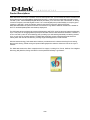
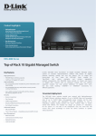
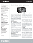
DGS-3620-28TC ver. A1 20 10/100/1000Base-T ports + 4 Combo 10/100/1000Base-T/SFP ports + 4 10GE SFP+ ports L3 Stackable Managed Switch DGS-3620-28TC-DC ver. A1 20 10/100/1000Base-T ports + 4 Combo 10/100/1000Base-T/SFP ports + 4 10GE SFP+ ports with DC power L3 Stackable Managed Switch DGS-3620-28SC ver. A1 20 SFP ports + 4 Combo SFP/10/100/1000Base-T ports + 4 10GE SFP+ ports L3 Stackable Managed Switch DGS-3620-28PC ver. A1 20 10/100/1000 PoE+ ports + 4 Combo 10/100/1000Base-T PoE+/SFP ports + 4 10GE SFP+ ports L3 Stackable Managed Switch DGS-3620-28SC-DC ver. A1 20 SFP ports + 4 Combo 10/100/1000Base-T/SFP ports + 4 10GE SFP+ ports with DC power L3 Stackable Managed Switch DGS-3620-52T ver. A1 48 10/100/1000Base-T ports + 4 10GE SFP+ ports L3 Stackable Managed Switch DGS-3620-52P ver. A1 48 10/100/1000Base-T PoE+ ports + 4 10GE SFP+ ports L3 Stackable Managed Switch External Specification Version 1.02 By: Stanley Chen Switch and Security Product Dept 2011/3/17 This document contains confidential information and may not be disclosed to persons without the written consent of D-Link Corporation. For any person not intended to be the recipient, please (i) do not disclose the contents to any other person; and (ii) promptly return/delete all existing copies 1/29 Version 1.00 Revised Date 2011/2/20 1.01 2011/3/16 1.02 2011/3/17 DGS-3620 Series Specification Revision History Person Name Content Revised Stanley Chen/ First Edition Stephen Tseng Stanley Chen Add GS Certificate/Report or LVD for Safety Certificates and Test Reports Stanley Chen/ To modify the description of FAN spec. Stephen Tseng 2/29 Product Descriptions: DGS-3620 series is the Layer 3 members of D-Link xStack product line. The DGS-3620-28TC/28TC-DC/28PC/52T /52P provide 24/48 10/100/1000Mbps Gigabit Ethernet ports, 4 combo SFP ports (28TC/28TC-DC/28PC) and 4 10G SPF+ ports. 10/100/1000Mbps Gigabit Ethernet ports allow you to connect to other LAN switches, or directly connect to the power users with Gigabit access. The 4 combo Gigabit ports provide flexibility on the port type for customers. 10GE SFP+ ports provide fiber uplinks for inter-device connection. With 24 SFP ports, DGS-3620-28SC/28SC-DC provide a full fiber environment for long distance Ethernet infrastructure, suitable for the FTTx and MAN (Metropolitan Area Network) deployment. The DGS-3620 series provides dual-propose uplink/stacking 10GE SFP+ ports for advanced network architecture. Up to 4 10G ports can be aggregated as uplink ports that allow maximum 40G backbone bandwidth. In addition, 2 of the 4 10G SFP+ ports can act as stacking ports, providing up to 40G stacking bandwidth per stacking member. Up to 12 units can be physically stacked. The DGS-3620 series also support Virtual Stacking that allows it to virtually stack with other D-Link switches, providing Single IP Management for small business. With the latest technology, DGS-3620 series Switches provide advanced L3 features including IPv4/v6 routing, QoS and ACL filtering. Packet routing and protocol filtering/inspection make the Switch act even as the Layer 4 switches. The DGS-3620 series also offers comprehensive IPv6 support, including IPv6 Tunnel, ICMPv6, IPv6 Neighbor Discovery (ND), DHCPv6, RIPng and OSPFv3. It also passed IPv6 Ready Logo Phase II. 3/29 Product Specifications: 1. Hardware Specifications General Features Operation Temperature Detailed Description - 19-inch, 1U Rack-mount size - Support Wall-mount DGS-3620-28PC/52T/52P - 441mm x 380mm x 44mm DGS-3620-28TC/28SC/28TC-DC/28SC-DC - 441mm x 310mm x 44mm DGS-3620-28TC: 4.15kg DGS-3620-28TC-DC: 4.15kg DGS-3620-28SC: 4.10kg DGS-3620-28SC-DC: 4.10kg DGS-3620-28PC: 5.76kg DGS-3620-52T: 5.13kg DGS-3620-52P: 6.30kg 0-50°C Storage Temperature -40-70°C Operation Humidity 10%-90% RH Storage Humidity 5% ~ 90% RH Dimension Weight Power Consumption Maximum Heat Dispassion Acoustic DGS-3620-28TC: 50.8W DGS-3620-28TC-DC: 51.5W DGS-3620-28SC: 60.2W DGS-3620-28SC-DC: 65.5W DGS-3620-28PC: 478.0W DGS-3620-52T: 81.0W DGS-3620-52P: 505.4W DGS-3620-28TC: 173.2 BTU/hr DGS-3620-28TC-DC: 175.6 BTU/hr DGS-3620-28SC: 205.3 BTU/hr DGS-3620-28SC-DC: 223.4 BTU/hr DGS-3620-28PC: 1630 BTU/hr DGS-3620-52T: 276.2 BTU/hr DGS-3620-52P: 1723.4 BTU/hr DGS-3620-28TC: Operation Temperature at: ~30°C: < 38.7dB 30°C~: < 46.5dB DGS-3620-28TC-DC: Operation Temperature at: ~30°C: < 38.7dB 30°C~: < 46.5dB DGS-3620-28SC: Operation Temperature at: ~30°C: < 38.9dB 30°C~: < 46.2dB DGS-3620-28SC-DC: Operation Temperature at: ~30°C: < 38.9dB 30°C~: < 46.2dB DGS-3620-28PC: 4/29 Operation Temperature at: ~30°C: < 40.3dB 30°C~: < 52.5dB DGS-3620-52T: Operation Temperature at: ~30°C: < 40.6dB 30°C~: < 51.1dB DGS-3620-52P: Operation Temperature at: ~30°C: < 43.2dB 30°C~: < 54.8dB MTBF DGS-3620-28TC: 287763.2892 Hours DGS-3620-28TC-DC: 372899.3973 Hours DGS-3620-28SC: 299801.4971 Hours DGS-3620-28SC-DC: 393367.7595 Hours DGS-3620-28PC: 230619.6475 Hours DGS-3620-52T: 255608.808 Hours DGS-3620-52P: 202462.1368 Hours Performance Switching Capacity Max. Forwarding Rate Forwarding mode DGS-3620-28TC/ 28TC-DC: 128Gbps DGS-3620-28SC/ 28SC-DC: 128Gbps DGS-3620-28PC: 128Gbps DGS-3620-52T: 176Gbps DGS-3620-52P: 176Gbps DGS-3620-28TC/ 28TC-DC: 95.24Mpps DGS-3620-28SC/ 28SC-DC: 95.24Mpps DGS-3620-28PC: 95.24Mpps DGS-3620-52T: 130.95Mpps DGS-3620-52P: 130.95Mpps Store and Forward Key Components SDRAM for CPU Flash Memory Packet Buffer memory Battery FAN DDR 256M bytes/32bit 128Mbytes NOR flash External SD card memory 2Mbytes On-board Golden Capacitor provides Real Time Clock (RTC) function which maintains the local time settings when the device power is off. - Fans are capable to adjust speed based on system temperature detected by the IC sensor. Power Features Power Supply External RPS Support AC input for DGS-3620-28TC/28SC/28PC/52T/52C 1. 100-240 VAC, 50/60Hz 2. Internal universal power supply DC input for DGS-3620-28TC-DC/28SC-DC 3. -36Vdc ~ -72Vdc 4. Internal universal power supply 1. Provide one connector in rear panel to install optional external RPS to enhance the reliability. When internal power fails, the optional external RPS will take over all the power immediately and automatically. 2. Support hot-swap function for RPS 3. RPS Support - DPS-500 (For DGS-3620) 5/29 - DPS-700 (For DGS-3620-28PC/52P) DGS-3620-28TC-DC/28SC-DC do not support RPS Port Functions A RJ-45 console port for out-of-band configuration of the software features. Default baud rate: 115,200bps Out-of-band Management Port A 10/100 RJ-45 Ethernet OOB management port for IP-based out-of-band (OOB Port) telnet, Web or SNMP management 1. An alarm connector in the rear panel that provides 2 input circuits for external event detection and 1 output circuit for alarm action 2. Switch will send out traps, logs and trigger the output alarm when two pins are shorted among the input pair Alarm Port * 3. Output alarm circuit support - 42 Vac, 50 Hz, 1A max - 60 Vdc, 1A max 4. Support configurable logs and traps for external alarms, up to128 characters user defined warning message can be inserted DGS-3620-28TC/-28TC-DC: - 24 10/100/1000Base-T with 4 combo SFP and 4 SFP+ ports DGS-3620-28SC/-28SC-DC: - 24 SFP ports with 4 combo 10/100/1000Base-T and 4 SFP+ ports DGS-3620-28PC: - 24 10/100/1000 POE Base-T with 4 combo SFP and 4 SFP+ ports DGS-3620-52T: - 48 10/100/1000 Base-T and 4 SFP+ ports DGS-3620-52P: - 48 10/100/1000 POE Base-T and 4 SFP+ ports Console Port 10/100/1000Base-T ports comply with following standards: - IEEE 802.3 compliance - IEEE 802.3u compliance - Support Full-Duplex operations - IEEE 802.3x Flow Control support for Full-Duplex mode - IEEE 802.3ab compliance - IEEE 802.3af compliance (DGS-3620-28PC & DGS-3620-52P only) - IEEE 802.3at compliance (DGS-3620-28PC & DGS-3620-52P only) Ethernet Ports SFP ports comply with following standards: - IEEE 802.3z compliance - IEEE 802.3u compliance (Firmware R2 support) Supported SFP Transceivers: - DEM-310GT (1000Base-LX, Single-mode, 10km) - DEM-311GT (1000ase-SX, Mutli-mode, 500m) - DEM-312GT2 (1000Base-SX, Multi-mode, 2km) - DEM-314GT (1000BASE-LX, Single-mode, 50km) - DEM-315GT (1000BASE-LX, Single-mode, 80km) - DGS-712 (1000BASE-TX) - DEM-330T/R (1000BASE-BX, WDM transceiver, Single-Mode 10km) - DEM-331T/R (1000BASE-BX, WDM transceiver, Single-Mode 40km) - DEM-210 (100Base-FX, Single-mode, 15km) * - DEM-211 (100Base-FX, Multi-mode, 2km) * - DEM-220T (100Base-BX, Wavelength Tx:1550nm, Rx:1310nm, Single-mode, 20km) * - DEM-220R (100Base-BX, Wavelength Tx:1310nm, Rx:1550nm, Single-mode, 20km) * 6/29 SFP+ ports comply with following standards: - IEEE 802.3ae compliance - IEEE 802.3aq compliance Supported SFP+ Transceivers: - DEM-431XT: 10GBASE-SR SFP+ Transceiver (w/o DDM), 80m: OM1 & OM2 MMF,300m: OM3 MMF - DEM-431XT-DD: 10GBASE-SR SFP+ Transceiver (with DDM), 80m: OM1 & OM2 MMF, 300m: OM3 MMF - DEM-432XT: 10GBASE-LR SFP+ Transceiver (w/o DDM), 10km - DEM-432XT-DD: 10GBASE-LR SFP+ Transceiver (with DDM), 10km - DEM-433XT: 10GBASE-ER SFP+ Transceiver (w/o DDM), 40km - DEM-433XT-DD: 10GBASE-ER SFP+ Transceiver (with DDM), 40km - DEM-435XT: 10GBASE-LRM SFP+ Transceiver (w/o DDM), 220m: OM1 & OM2 MMF, 300m: OM3 MMF - DEM-435XT-DD: 10GBASE-LRM SFP+ Transceiver (with DDM), 220m: OM1 & OM2 MMF, 300m: OM3 MMF - DEM-436XT-BXU: 10GBASE-LR BiDi SFP+ Transceiver (w/o DDM) 20km, TX: 1270nm, RX: 1330nm - DEM-436XT-BXD: 10GBASE-LR BiDi SFP+ Transceiver (w/o DDM) 20km, TX: 1330nm, RX: 1270nm - DEM-310GT (1000Base-LX, Single-mode, 10km) - DEM-311GT (1000ase-SX, Multi-mode, 500m) - DEM-312GT2 (1000Base-SX, Multi-mode, 2km) - DEM-314GT (1000BASE-LH, Single-mode, 50km) - DEM-315GT (1000BASE-ZX, Single-mode, 80km) - DEM-330T/R (WDM transceiver, Single-Mode 10km) - DEM-331T/R (WDM transceiver, Single-Mode 40km) Supported SFP+ Direct Attached Cables: Direct Attached Cable is a cable with built-in SFP+ transceivers at both ends - DEM-CB100S: 10-GbE SFP+ 1m Direct Attach Cable ・- DEM-CB300S: 10-GbE SFP+ 3m Direct Attach Cable - DEM-CB700S: 10-GbE SFP+ 7m Direct Attach Cable 2 SFP+ ports among the 4 SFP+ ports are dual-purpose for either physical Stacking Ports stacking or uplink PoE Capability (DGS-3620-28PC & DGS-3620-52P) 1. Compliant with IEEE 802.3af/802.3at PoE standards. 2. Supplies power to PD device up to 15.4W per port (802.3af) or 30W+ per port (802.3at) PoE Specification 3. Power Budget: 370W 4. Auto discovery: automatically discovers the connection of PD device and immediately sends power to it 7/29 5. Active circuit protection: automatically disables the port if there is a short or the port current is over 600mA 6. Provide power following the classification below Class Usage Max power sent by PSE 0 Default 15.4W 1 Optional 4.0W 2 Optional 7.0W 3 Optional 15.4W 4 Reserved 31.8W Class 0 1 2 3 4 Usage Default Optional Optional Optional Reserved Max power received by PD 13.0W 3.84W 6.49W 13.0W 25.5W 7. Follow the standard PSE pin-out standard of Alternative A, which sends power over number 1,2,3,6 pins of 8 wires of CAT3 ~ 6A UTP cable for 802.3af or CAT5e~ 6A UTP cable for 802.3at 8. DGS-3620-28PC, DGS-3620-52P work with all D-Link 802.3af and 802.3at capable devices, and work with all non-802.3af and non-802.3at capable D-Link AP, IP Cam and IP phone via DWL-P50. * To be supported via future firmware release. 2. Software Features 2.1 Standard Image Feature Detailed Description Standard Release Schedule Stackability 1. Support D-Link Single IP Management v1.61 2. Use a single IP to manage the virtual stack with up to 32 D-Link xStack devices 1. Via the SFP+ stacking ports to provide bi-directional redundant stacking topology 2. Topology: Linear/Ring 3. Bandwidth: Up to 40G (full duplex) Physical Stacking 4. Support up to 12 units per stack 5. Support backup master 6. Allows Link Aggregation or mirroring to span across multiple units of the stack L2 Features 1. 32K MAC Address Table MAC Address 2. Support 256 static MACs 1. 802.3x when Full Duplex Flow Control 2. Back Pressure when Half Duplex 3. Head-of-line blocking prevention Jumbo Frame Up to 13Kbytes Virtual Stacking 8/29 FCS FCS FCS FCS FCS 1. Support 802.1D 2004 STP/RSTP; 2. Support 802.1Q 2005 MSTP 3. Support MSTP with maximum 64 MSTP Instances 4. Support per port / per device BPDU filtering 5. Support 802.1D STP 2004 edition 6. Support Root Restriction(defined in 802.1Q-2005) 7. Support edge port in STP/RSTP/MSTP mode 8. Support forwarding BPDU when STP function is disabled Spanning Tree 9. Support optional destination address (Bridge Group Address/Provider Bridge Group Address) on Service Provider network 10. Support external debug command 11. Support per-port MAC: the source address field of MAC frames conveying BPDUs supported by the Bridge conveys the individual MAC Address for the Bridge Port through which the PDU is transmitted. - D-Link LBD v4.0 Loopback - STP independent Detection (LBD) - Support per port/per VLAN shutdown 1. Comply with 802.1AX and 802.3ad 2. Support max 32 groups per device, max 8 Gigabit or 10G ports per group 3. High availability LACP to prevent single or multiple port failure in an aggregation channel. IEEE 4. Support following load sharing mechanism 802.3ad, Link Aggregation - Source MAC IEEE - Destination MAC 802.3AX - Source MAC + Destination MAC - Source IP - Destination IP - Source IP + Destination IP 5. Support cross-stack trunk 1. Support Mirroring for Tx/Rx/Both 2. Mirroring support following mode - One-to-one mode - Many-to-one mode - Per flow mode Mirroring - RSPAN 3. Multiple-session mirroring (up to 4 mirror target ports including RSPAN. The source port for each target port can not be overlapped) 4. Support cross-stack mirroring Support tunnels for the following protocols across the service provider's networks L2 Protocol - GVRP Tunneling - STP - Protocol MAC Type: 01000CCCCCCC, 01000CCCCCCD 1. Best case supports 50ms recovery time in a 16-node ring structure with the circumference less than 1,200 Km ERPS (Ethernet 2. Support multiple ring topology, maximum 2 rings ITU-T Ring Protection inter-connected via a shared link G.8032 Switching) 3. Support 26 single rings in DGS-3620-52T/52P and 14 single rings in DGS-3620-28TC/SC/PC 4. Supported by hardware that accelerates the recovery time VLAN 9/29 FCS FCS FCS FCS FCS FCS 802.1Q Support 802.1Q 2005 edition 1. Be able to configure the untagged port of different protocols on the same physical port 2. Be able to configure 802.1Q and 802.1v untagged port on same 802.1v physical port 3. Support multiple VLANs for each protocol 4. Support VLAN classification based on EtherType 1. Total 4K VLAN groups; VLAN Group 2. Max. 4K static/ 255 dynamic VLAN groups; 3. Configurable vid from 1~4094 1.Support VLAN tagging based on PVID Port-based VLAN 2.Support VLAN classification based on default port priority 1. Support 256 dynamic VLANs GVRP 2. GVRP advertisement on both dynamic and static VLANs 3. GVRP can be enabled/disabled by per port/VLAN/system basis MAC-based VLAN Support 1024 entries Allow a physical network interface to carry and pass multiple VLAN Trunking tagged VLAN traffics so different VLAN information can be exchanged between switches Asymmetric VLAN 1. Support up to 5 dedicated ISM VLANs 2. Be able to filter unknown multicast packets per ISM VLAN 3. Support tagged and untagged members while the port still belongs to: - Port-based VLAN - 802.1Q VLAN whose VID is different from ISM VLAN 4. The IGMP snooping function in ISM VLAN is independent from global IGMP snooping 5. Support IGMP v1/v2/v3 and MLD v1/v2 ISM VLAN 6. Support up to 80 ISM profiles per system, each ISM VLAN can bind up to 16 profiles 7. Each ISM profile can support up to 32 address ranges 8. Source ports can be untagged 9.Support the modification of ISM VLAN's priority level for better traffic control 10.Support the configuration of two ISM VLAN source ports on the switch. When working with STP , it will allow the forwarding of multicast stream using backup link in case the primary link goes down Private VLAN 1. Support 256 entries Subnet-based 2. Support VLAN classification based on VLAN - Source IP and subnet mask 3. Support IPv4/v6 Source IP Super VLAN 1. Identify the voice VLAN by MAC address Voice-VLAN 2. Identify the voice VLAN by LLDP-MED 10/29 FCS FCS FCS FCS FCS FCS FCS FCS FCS FCS FCS FCS FCS 1. Port-based Q in Q 2. Add SVLAN tag to either untagged or single tagged packets and generate double tagged packets 3. Support Selective Q-in-Q. Add SVLAN tag based on - PVID (for untagged packets only) - CVLAN tag 4. Support untagged / single tagged / double tagged at same physical port Q in Q UNI Port: For packets ingress from UNI port, the packet can be untagged, or CVLAN tagged Based on user configuration, SVLAN tag can be added to the packet, or CVLAN tag be replaced with SVLAN tag The learning and forwarding is based on SVLAN. NNI Port: For packets ingress from NNI, it can be untagged, or single SVLAN tagged, or double tags. The switch's learning and forwarding is based on SVLAN. (CVLAN tag is identified by CVALN TPID. SVLAN tag is identified by SVLAN TPID.) FCS 5. Per port configurable SVLAN TPID 6. Support up to 4 SVLAN TPID ( Per port & per system) 7. Per system configurable CVLAN TPID 802.1ak (MRP) R2 1. Automatically detect device type and assign associated D-Link Intelligent device policies simultaneously Port Management R2 2. Device policies include several applications such as VoIP, (IPM) Surveillance, and Storage L2 Multicasting Support L2 multicast filtering modes as below L2 Multicast - Forward all groups FCS Filtering - Forward all unregistered groups - Filter all unregistered groups 1. Support IGMP snooping v1, v2, v3 2. 1K IGMP snooping groups; 3. Support 64 static multicast addresses; 4. Can configure a port as a static router port, or can forbid a port to be learnt as a router port. 5. Per VLAN IGMP Snooping 8. Support Host-based IGMP Fast Leave RFC2236, 9. IGMP Snooping Report Suppression: When IGMP report IGMP Snooping 3376, 4541 FCS suppression is enabled, the switch sends the first IGMP report from all hosts for a group to all the multicast routers. The switch does NOT send remaining IGMP reports for the group to the multicast routers. This feature prevents duplicate reports from being sent to the multicast devices. 10. Support IGMP messages rate limit per port / per VLAN 11. Support snooping counter 13. Support snooping switches (RFC4541) 11/29 MLD snooping 1. 1K MLD snooping groups; 2. Support 64 static multicast addresses; 3. Can configure a port as a static router port, or can forbid a port to be learnt as a router port. 4. Per VLAN MLD Snooping 5. Support L2 multicast filtering modes as below - Forward all groups - Forward all unregistered groups - Filter all unregistered groups 6. Support MLD v2 snooping 7. Support host-based MLD fast leave 8. Support MLD messages rate limit per port / per VLAN 9. Support snooping counter 10. Support snooping switches(RFC 4541) FCS 1. Support 256 IP interfaces 2. Support max 256 IP interfaces per VLAN 3. Support IPv4 address 0.0.0.0 to prevent the switch from occupying an IP address in the network. FCS Support 8 IPv4/v6 interfaces FCS L3 Features IP Interface Loopback Interface Null Interface ARP ARP Proxy VRRP FCS 1. Max 8 ARP entries 2. Support 256 static ARP 3. Support Gratuitous ARP 1. Support ARP Proxy between different subnets 2. Support Local ARP Proxy in the same subnet 1. Owner / non-owner ping response 2. Support text authentication IPv6 Ready Phase IPv6 Ready Logo Phase 2 compliant 2 L3 Routing 1. Total 12K routing entries shared by IPv4/6 Routing Table Size - Max 12K entries for IPv4 dynamic route - Max 6K entries for IPv6 dynamic route 1. Total 8K L3 H/W forwarding entries shared by IPv4/v6 L3 Forwarding - Max 8K IPv4 entries Table Size - Max 4K IPv6 entries 1. Total 256 entries shared by IPv4/v6 - Max 256 IPv4 entries - Max 128 IPv6 entries Static Route 2. Secondary static route 3. Equal Cost / Weighted Cost multi-path route 4 Support route redistribution 1. Support IPv4/v6 secondary default route Default Route 2. Support Equal Cost / Weighted Cost multi-path route 3. Support route redistribution RIP Support RIP v1/v2 12/29 FCS RFC1072 FCS RFC2338 FCS FCS FCS FCS FCS FCS FCS OSPF Policy Based Route IP Directed Broadcast Multi Path Routing 1. OSPF v2 2. OSPF Passive Interface 3. OSPF NSSA (Not So Stubby Area) 4. Support 16 OSPF areas 5. OSPF Equal Cost Multi-Path route 6. Support 512 OSPF Equal Cost Multi-Path routes, up to 4 paths per destination. 7. Support OSPF announcement via loopback interface 8. Support the advertisement of default route into OSPF without the need to manually redistribute static route Based on ACL FCS FCS Support enable/disable of IP directed-broadcast function FCS 1. Support both Equal Cost (EC) and Weighted Cost (WC) 2. Max 32 static multi path routes, 4 paths per destination FCS BFD(Bidirectional 1. Support OSPF Forwarding 2. Support VRRP Detection) L3 Multicasting 2K Multicast Groups. Both static multicast groups and dynamic Multicast table multicast groups share these entries. size - Max 64 IGMP static multicast groups - Max 2K dynamic multicast groups 1. Max dynamic IGMP groups: 4096 IGMP v1/v2/v3 2. Max source record number: 4096 3. Max static IGMP groups:1K 1. Support v1/v2 MLD 2. Max dynamic MLD groups: 2048 3. Max source record number: 2048 1. Can enable IGMP Proxy per-VLAN basis - configure upstream VLAN IGMP/MLD Proxy - configure downstream VLAN 2. Support max.128 downstream IGMP proxy groups and 32 downstream MLD proxy groups 1. Filter IGMP join packets 2. Support port based filtering 3. Support up to 60 profiles and each profile can add up to 32 Limited IP multicast groups. Multicast (IGMP 4. Configurable max. number of multicast groups that a port can Filtering) join, ranging from 1~1K 5. Support replace and drop action while group number per port/vlan exceeds max mcast groups Multicast Hardware packet replication up to 32 VLANs per group Duplication Static IP Multicast Route Support IPv4 PIM DM 1. Max PIM-DM neighbor: 100 2. IPMC cache table size: 2048 (share with DVMRP) 13/29 TBD FCS FCS FCS RFC1112, FCS 2236, 4605 FCS FCS FCS FCS PIM SM Support IPv4: 1. Max PIM-SM neighbor: 100 2. PIM-SM multicast routing table size: 4096 (max to 2048 different groups) 3. CRP table size: 40 4. Static RP table size: 20 5. RP address table size: 40 Support IPv4 PIM-SSM PIM Sparse-Dense Support IPv4 Mode QoS(Quality of Service) 802.1p support Number of 8 Queues per port Queues Support following modes Queue handling - Strict - Weighted Round Robin(WRR) Be able to classify packets according to follow contents: - 802.1p priority - VLAN - MAC address - Ether type - IP address Class of Service - DSCP - Protocol type - TCP/UDP port number - IPv6 Traffic Class - IPv6 flow label - User defined packet content Support following actions for flows - Remark 802.1p priority tag QoS Flow Actions - Remark TOS/DSCP tag - Bandwidth Control 1. Support Two Rate Three Color Marker (trTCM) - CIR/PIR minimum granularity: kbps Three Color - Support CBS/PBS Marker 2. Support single rate three color marker (srTCM) - CIR minimum granularity: 1kbps - Support CBS/EBS 1. Support Port and Flow based bandwidth control Bandwidth Control 2. Minimum granularity 64Kbps Time-based QoS Support up to 64 time range profiles ACL(Access Control List) Maximum Ingress ACL: support 6 profiles and 256 rules per profile Mask/Profiles Egress ACL: support 4 profiles and 128 rules per profile 14/29 FCS FCS FCS FCS FCS FCS RFC2475, 2598 FCS FCS RFC2697, RFC2698 FCS FCS FCS FCS ACL Policy Time Based ACL ACL Statistics CPU interface filtering Security ACL policy supports following packet contents: - 802.1p priority - VLAN - MAC address - Ether type - IP address - DSCP - Protocol type - TCP/UDP port number - IPv6 Traffic Class - IPv6 flow label - User defined packet content Support up to 64 time range profiles Max 5 profiles, 100 rules FCS FCS FCS FCS 1. Support SSH v2 2. Support IPv4/v6 access SSH v2 3. Support user selectable port number other than default port 22 1. Support v1/v2/v3 SSL 2. Support IPv4/v6 access Port Security 1. Support 64 MACs per port 1. Allow specifying the threshold in terms of pkt/s for per port. Min granularity: 1pkt/s 2. Be able to set up a storm threshold. When broadcast / multicast Broadcast/Multica /unknown unicast traffic hit the defined threshold, the switch will st/Unicast Storm start blocking or discarding packets which would otherwise Control 'flood' the network. The blocked port will be activated again only when the broadcast/ multicast/ unknown unicast traffic falls below the defined threshold. 3. Allows the configuration of recovery timer for shutdown ports Traffic Segmentation 1. System will send out trap and log when CPU utilization hit the D-Link Safeguard definable threshold Engine 2. Protect CPU from Broadcast / Multicast / Unicast flooding 3. Protect CPU from protocol control packet attacks BPDU Attack Switch has 3 options when a port receives BPDU packet: Protection Drop BPDU packets, drop all packets, or shutdown port ARP Spoofing Prevention 1. Support D-Link IMPB v.3.9 2. Support 500 address binding entries per device 3. ARP Inspection IP-MAC-Port 4. IP Inspection (IPv4/v6) Binding 5. Support IPv4/v6 DHCP Snooping 6. Support IPv6 ND Snooping 7. Support IMPB debug command in CLI mode NetBIOS/NetBEUI Support IP & non-IP (802.3) modes (Default: IP mode) filtering DHCP Server Support log/trap triggering when receiving any illegal DHCP Screening server packet 15/29 FCS FCS FCS FCS FCS FCS FCS FCS FCS FCS FCS DHCP client filtering MAC Blackhole Secure FTP DoS Attack Prevention AAA FCS R2 R2 R2 802.1X 1. Support local/RADIUS database 2. Support Port-based Access Control 3. Support Host-based Access Control - Maximum 448 MACs per port/per system 4. Be able to configure 802.1X packet transparent / filtering when 802.1X is disable 5. Support EAP, OTP, TLS, TTLS and PEAP 6. Support MD5 authentication 7. Support 802.1x session timeout attribute 8. Identity driven policy assignment: RFC3580 - Can assign VLAN, ingress/egress bandwidth control, ACL and 802.1p default priority to the port based on the attributes dispatched from the RADIUS server. - Support 802.1x extension: "Assign user priority/bandwidth based on MAC” 9. Support "RFC3580 tag1/2 format” (compatible with Cisco ACS server) 10. Support per-VLAN authentication in order to support client roaming 11. Can relay Radius reply message to the client FCS Web-based Access Control 1. Support local/RADIUS database - Maximum 16 MACs per port when using local database - Maximum 16 MACs per device when using local database - Maximum 4000 MACs per port when using RADIUS database - Maximum 4000 MACs per device when using RADIUS database 2. Support logout and logout timer functions 3. Support Port-based authentication 4. Support Host-based authentication 5. Identity driven policy assignment: Can assign VLAN, ingress/egress bandwidth control, ACL and 802.1p default priority to the port according to the attributes dispatched from RADIUS server. 6. Support HTTPS 7. Detailed port auth_state description 8. Support default redirect Web page. 9. Support per-VLAN authentication in order to support client roaming. 10. Support IPv4/v6 address FCS 16/29 1. Support local/RADIUS database - Maximum 1024 MACs per port when using local database - Maximum 1024 MACs per device when using local database - Maximum 4000 MACs per port when using RADIUS database - Maximum 4000 MACs per device when using RADIUS MAC-based database Access Control 2. Support Port-based authentication 3. Support Host-based authentication 4. Identity driven policy assignment which can base on the attributes dispatched from the RADIUS server: a. Assign ingress/egress bandwidth control, ACL and 802.1p default priority to the port b. Assign VLAN to the port or user 1. Support Q-server (NTT and OKI authentication server) - It includes authentication, quarantine, and access management 2. Support Dynamic VLAN assignment 3. Support Radius server failover to local user Database 4. Support ACL assignment after successful authentication 5. Supports FQDN URL for JWAC redirect page 6. Show IP address and user ID in web GUI and log 7. Support authentication page elements customization. 8. Support Compound Authentication. JWAC 9. Support per-VLAN authentication. 10. Support roaming. 11. Max on-line clients(the user who finished authentication, blocked and authenticating): - 4000 per port - 4000 per device - 4000 per system 12. Max concurrent authentication sessions(the users who are authenticating): - 50 per port(configurable) 1. Support Microsoft NAP function via 802.1X guest VLAN Microsoft® NAP 2. Support 802.1X NAP Support 3. Support DHCP NAP Port-based guest VLAN Support following authentication method - 802.1X Guest VLAN - Web-based Access Control (Only in Compound Authentication mode) - MAC-based Access Control Support 4 level user account - User: allowed to execute ‘show’ and some troubleshooting commands (like ping) - Power user: allowed to execute all commands except the User Account ones related to account management and service Privilege for Mgm (telnet/SSH/Web/SNMP/RMON/sFlow etc.) Access enablement/disablement - Operator: allowed to execute all commands except the ones related to account management - Administrator: can execute all switch commands. 17/29 FCS FCS FCS FCS FCS RFC2138, 2139, 2865, FCS 2866, 2618 RADIUS Auth. for Mgmt Access TACACS+ Auth. for Mgmt Access Support Zone Defense technology RFC1492 FCS FCS 1. Support Network accounting (for 802.1x user) 2. Support EXEC accounting (for Mgm Access) 3. Support System accounting (for Mgm Access) 1. OR: enable any of the authentication (802.1X/MAC/JWAC/WAC) on a port, client only needs to pass any authentication to gain access Compound 2. AND:Support following authentication criteria Authentication - dot1X_IMPB: must pass 802.1X(first) & IMPB - IMPB_JWAC: must pass IMPB(first) & JWAC - IMPB_WAC: must pass IMPB(first) & WAC - MAC_IMPB: must pass MAC(first) & IMPB Allows to configure the switch to check local database or bypass Authentication authentication when configured RADIUS server fails Database failover - Support WAC, JWAC, 802.1X, MAC, Compound authentication Management Single IP Support D-Link SIM v1.61 Management LLDP LLDP-MED 1. Compatible with following browsers - IE5.5 or later version - Netscape Web-based GUI RFC2068 - Mozilla - Firefox 2. Support IPv4/v6 CLI ZModem Telnet Server Support IPv4/v6 RFC854 Telnet Client Support IPv4/v6 TFTP client Support IPv4/v6 RFC783 RFC1157, RFC1901, SNMP v1/v2c/v3 RFC1908, RFC2570, RFC2575 RADIUS Accounting 18/29 FCS FCS FCS FCS FCS FCS FCS FCS FCS FCS FCS FCS SNMP Trap System Log Trap/ Alarm/ Log Severity Control RMON v1 RMON v2 sFlow BootP/DHCP client Supports following Trap events - New MAC Notification - Power and fan errors - Cold / Hot start-up - Link state change - STP state change: support port STP state change. (ex. Forwarding->blocking) - SNMP authentication failure - Management Access Login failure: no id or password error, no privilege for access, no authentication server, or server timeout. -Management access login fail. -802.1x access login fail -WAC access login fail - MAC access login fail - MAC access login fail - Port Security violation - Fan status - Firmware upgrade via SNMP is finished - IP-MAC-Port Binding access violation - Loopback occurring and recovery - Send a trap after save - DHCP Server Screening - Gratuitous ARP - LACP Trap 1. Support IPv4/v6 log server 2. Support WAC/MAC log information RFC3164 3. Support the log for storm control block mode Be able to divide the events into 8 severity levels and trigger corresponding logging activities based on the defined severity levels. Support 4 groups (statistics, history, alarm and event) RFC2819 Support Probeconfig group 1. Support Port-based flow sampler and counter poller 2. Support max 256 leading bytes for flow sampling RFC3176 3. Support sFlow version 5 4. Support IPv4/IPv6 server RFC951, Support IPv4 / IPv6 RFC1542, 2131 DHCP Auto-configuration FCS FCS FCS FCS FCS FCS FCS FCS 19/29 DHCP Server DHCP relay Support IPv6: DHCPv4 server: 1. Support max 10 pools, the max number of IP addresses per pool is 1024. 2. Support max 16 manual bindings. 3. Max number of excluded address range is 5. 4. Max number of router address is 3. 5. Max number of DNS address is 3. 6. Max number of NetBIOS address is 3. DHCPv6 server: 7. Max 16 pools and total 4096 available IPv6 addresses. Max 4096 IPv6 addresses are supported per pool, but the total IPs in 16 pools can’t be more than the total number 4096. 8. Support max 64 manual bindings. 9. Supports max 4 reserved IPv6 address ranges per pool. 10. Max number of DNS address is 2. 1. Support DHCP relay option 82, 60, 61 2. Option to select primary or secondary relay IP interface 5. Support IPv4/v6 DHCP relay UDP helper Scheduling a Reload of the Software Image WOL (Wake-on-LAN) DNSv6 FCS FCS R2 R2 R2 R2 1.Send trap/log for door open, Smoke gauge, or temperature sensor 2. Turn on external air conditioner or external fan. Trap/ Alarm/ Log Severity Control Alarm DO (output) function pin define be as follow: Normal off: contacts connect the common pin when the relay is activated; the circuit between Normal ON pin and Common pin is disconnected when the relay is inactive. R2 Normal on: contacts disconnect the common pin when the relay is activated; the circuit between Normal ON pin and Common pin is connected when the relay is inactive. Multiple Images Multiple Configuration Flash file system Port Description Editable Login Banner Editable System Prompt CPU Monitoring Password Recovery Password Encryption SNTP FCS Keep static IPIF config while reset system Keep static VLAN config while reset system Applied on inserted SD card.(SD Card: Fat32/Fat16) FCS FCS FCS Max support 6*80 characters of editable login banner FCS Max support 16 characters of editable prompt FCS Allow monitoring the utilization of CPU via Web/ CLI/ SNMP FCS FCS FCS Time Setting FCS 20/29 Provide precise time synchronization with grandmaster clocks. IEEE1588 Supported when the switch is not physically stacked. Supported when the switch is physically stacked Support “Show tech support” like Cisco Debug Command Record exception log when device enters critical error. Trusted Host 1. Support 10 trusted hosts MTU Setting RFC1191 Used to support Microsoft server load balancing application where multiple servers can share the same IP and MAC Network Load address. The request from clients will be forwarded to all Balancing (NLB) servers, but will only be processed by one of them. 1. Network Load Balance in Layer2; max. 10 entries 2. Network Load Balance in Layer3; max. 12 entries 1.Support 24 lines, each line support 80 bytes Greeting Message 2. Support Ctrl+V Paste hot key OAM 1. Comply with SFF-8472 real time access to optical transceiver operating parameters 2. Support configurable warning and auto shut down threshold for Optical following events Transceiver Digital - Internally measured transceiver temperature Diagnostic - Internally measured transceiver supply voltage Monitoring (DDM) - Measured TX bias current in uA - Measured TX output power in mW - Measured RX received optical power in mW 3. Support trap/log for both thresholds 1. Support 802.3ah link layer remote loopback and discovery 2. 802.3ah D-Link extension: D-link Unidirectional Link Detection (DULD) 802.3ah Ethernet 3. Support following dying gasp PDUs and traps: Link OAM - Power failure - Device reboot - All fans fail Green Time-based PoE PoE ports can be turned on/off by port or system through schedule or admin control (enable/disable forever) via GUI or command. Power Saving 1. Support power saving function on all Gigabit RJ-45 ports 2. Support 2 power saving modes Precision Time Protocol (PTP) ‐ Link status mode ‐ Cable length mode MIB MIBII Bridge MIB SNMPv2 MIB RFC1213 RFC4188 RFC1907 RFC1757, RFC2819 RFC2021 RFC1643, RFC2358, RFC2665 RFC 4836(MAU) RFC4363 RMON MIB RMONv2 MIB Ether-like MIB 802.3 MAU MIB 802.1p MIB 21/29 FCS R2 FCS FCS FCS FCS FCS FCS FCS FCS FCS FCS FCS FCS FCS FCS FCS FCS FCS IF MIB RADIUS Authentication Client MIB IGMPv3 MIB RIPv2 MIB IP Forwarding Table MIB(CIDR) IPv4 Multicast Routing MIB PIM MIB for IPv4 RADIUS Accounting Client MIB Ping MIB Trace out MIB L2 Specific MIB L3 Specific MIB OSPFv2MIB VRRP MIB Private MIB Entity MIB ZoneDefense MIB Standard Compliance IPv6 Ready Logo IPv6 Ready Logo Phase II RFC2233, RFC2863 FCS RFC2618 FCS RFC1724 FCS FCS RFC4292 FCS RFC2932 FCS RFC2934 FCS RFC2620 FCS RFC1850 RFC2787 RFC2737 FCS FCS FCS FCS FCS FCS FCS FCS FCS FCS 2.2 Enhanced Image VLAN 802.1Qbb L3 Features Priority-based Flow Control(PFC) on 10G ports. 1. Support following tunnel type - Static - GRE IPv6 Tunneling - 6to4 - ISATAP 2. Support RA for ISATAP Tunnel Max 256 virtual routers L3 Routing Support MD5 Authentication 1. Max peer number: 5 2. Max peer group number: 5 BGP 3. Max network entries: 256 4. Max aggregate entries: 256 5. Max AS-path access list entries:16 6. Max community list entries:64 RIPng(IPv6) OSPFv3 BGP+ L3 Multicasting 22/29 TBD RFC3056, RFC5214 FCS FCS FCS FCS R2 PIM SM DVMRP v3 OAM Cable Diagnostics Connectivity Fault Management (CFM) Support IPv6: 1. Max PIM-SM neighbor: 100 2. PIM-SM multicast routing table size: 2048 (up to 1024 different groups) 3. CRP table size: 40 4. Static RP table size: 20 5. RP address table size: 40 1. Max DVMRP neighbor: 100 2. IPMC cache table size: 2048 (shared with PIM-DM) 3. DVMRP routing table size: 1024 Support cable diagnostic function to check the status of connected RJ-45 cables. 1. Support 802.1ag 2. Support customer and operator/intra carrier maintenance domain levels(all MD levels (0-7). 3. Configurable maintenance level. The default customer level is 5 and the default operator level is 2 4. Support up to 256 MIPs and 128 MEPs at the same time 5. Support following functions for customer levels: - Per port and per VLAN basis MIP and MEP - LinkTrace and loopback reply for each MIP - Loopback Message (LBM) function that can generate LBM toward broadband access network - Loopback reply (LBR) function towards its peer MEP(s), in response to a unicast or multicast LBM 6. Support following functions for operator levels: - Per port and per VLAN basis MIP and MEP - Linktrace and loopback reply for each MIP - Be able to receive a LBM from its peer MEPs and initiate the associated LBR, for the MEP on the network interface - Be able to receive a LinkTrace Message (LTM) from its peer MEP and initiate the associated LinkTrace Reply (LTR) for the MEP on the network interface - Be able to receive a Continuity Check Message (CCM) from its peer MEPs and initiate the CCM, for the MEP on the network interface - Be able to initiate the LBM, LTM and CCM on a per-network interface/per-VLAN basis 7. Support minimum 10ms or 100ms CCM packet transmission -For 10ms CCM packet transmission, it needs to use H/W based CCM transmission to avoid high CPU usage . But there are some limitations: 1) not support “sender ID TLV”; 2) not support hardware “MIP” and “MIPCCM”; 3) may not support hardware “Packet statistics counters”; 8. Support user defined LBM payload with MTU up to 1,500 bytes 9. Support show function for - MIPCCM detail information - Packet statistics counters - Sender ID TLV in all PDUs - Port status TLV & interface status TLV CCM PDUs 10. Support H/W or S/W based CCM transmission 11. Be able to configure 1p priority of CFM (CCM, LTM, LBM) independently 12. Be able to enable/disable MIP LTM reply 23/29 FCS FCS FCS FCS MPLS/VPLS VRF MPLS Label Management LDP MPLS L3 VPN (MPLS / BGP VPN) MPLS L2 VPN (VPWS) VPLS - Support 128 VRF - Multi-ARP Table - Multi-Route Table(every VRF has absolute route table) - Multi-Transport Table(every VRF has absolute table) - RIP(VRF multi-example) - OSPF(multi-example, support VRF-LITE) - BGP(support multi-address family) - VRF aware DHCP - VRF aware SNMP - VRF aware SYSlog - VRF aware AAA - VRF aware TACACS+ - VRF aware tftp - MPLS stack levels: - Maximum number of labels: 2 One layer: 192K Two layers: inner layer:192K,outer layer: 4K - Label assign/preserve/check - Label free - Support 128 LDP neighbors - Support 400 LDP sessions - LDP basic discover mechanism - LDP expansion discover mechanism - LDP session creation and maintenance - LSP creation based on route top - Process Label mapping message - Process Label withdraw message - Process Label release message - PHP - Support 128 VPNs - VRF interface management - VPN-IPv4 route add |delete |update - VRF interface management - VRF route table size limitation - Inter-access between VPN - Inter-domain - Access Internet - Create /delete LDP connection - Support 4K PW - Receive label mapping message from remote session - Receive label withdraw message from remote session - Receive label release message from remote session - Receive label request message from remote session - Process interface event - VPLS neighbor discover based on BGP - VPLS LSP create /delete based on LDP - Create /delete VPLS pseudo wire - Delete MAC Standard Compliance MEF Comply with MEF 9 & 14 EPL, EVPL and E-LAN Certification 24/29 R2 R2 R2 R2 R2 R2 R2 3. Mechanism & ID Design 3.1 Name Plate Design DGS-3620-28TC DGS-3620-28TC-DC DGS-3620-28SC DGS-3620-28SC-DC DGS-3620-28PC DGS-3620-52T DGS-3620-52P 3.2 Rear Panel Design DGS-3620-28TC 25/29 DGS-3620-28TC-DC DGS-3620-28SC DGS-3620-28SC-DC DGS-3620-28PC DGS-3620-52T DGS-3620-52P 3.3 LED Indicator Location LED Indicative Color Power Green Console Green Per Device MGMT SD Green Green Status Description Solid Light Power On Light off Power Off Solid Light Console on Light off Console off Solid Light Light off Console on When there is a secure connection (or link) to 10/100Mbps Console off Solid Light Plug in Blinking Read/Write Blinking 26/29 Red RPS Green Light off No link Solid Light Read/Write failed Solid Light RPS in using Light off RPS off When switch detects that RPS cable is connected Blinking PoE push button (refer to DGS-3120) Off Light off When device is a stacking master, stacking ID will be 1, and when device is a stacking slave, stacking ID will be others. When there is a secure connection (or link) to 1000Mbps Ethernet device at any of the ports. When there is a secure connection (or link) to 1000Mbps device at any of the ports. When there is a secure connection (or link) to 10/100Mbps Ethernet device at any of the ports. When there is a secure connection (or link) to 10/100Mbps Ethernet device at any of the ports. No link Green Solid Light Power feeding Solid Light Error Condition Light off No Power feeding When there is a secure connection (or link) to 1000Mbps Ethernet device at any of the ports. When there is reception or transmission (i.e. Activity--Act) of data occurring at a 1000Mbps port. No Link When there is a secure connection (or link) to 10G bps Ethernet device at any of the ports. When there is reception or transmission (i.e. Activity--Act) of data occurring at a 10G bps port. When there is a secure connection (or link) to 1000Mbps Ethernet device at any of the ports. When there is reception or transmission (i.e. Activity--Act) of data occurring at a 1000Mbps port. Link down Stacking ID Green Capable 1-12 Solid Light Green Blinking Link/Act Solid Light LED Per 10/100/1000 Mbps Port Orange Blinking PoE Mode Orange Off Solid Light Per SFP Port Link/Act Green Blinking Off Off Solid Light Green Blinking SFP+ Port Link/Act Solid Light Orange Blinking Off Light off 3.4 Mechanical Metal Case ■ 19" Metal Case □ 11" Metal Case Plastic Case □ D-Link Big Size 235x162x36mm □ D-Link Small Size 142x109x31mm □ D-Link Mini D Size 90x82x31mm □ Others □ Others □ D-Link Middle Size 193x118x31mm □ D-Link Palm Size 104x61x28mm □ D-Link Pocket Size 80x52x27mm 27/29 4. Certifications: 4.1 EMC/RF Certificates and Test Reports EMC Test Report V V V V CE Report (89/336/EEC, 2004/108/EC) FCC/IC Report (FCC CFR 47, Part 15B/ ICES-003) C-Tick Report VCCI Report Class A V V V V RF Test Report CE Report (R&TTE:1999/5/EC) FCC/IC Report (FCC CFR 47, Part 15C, E/ RSS-210 ) C-Tick Report VCCI Report Class B Wireless Remarks Remarks *FCC/IC ID 4.2 Telecom. Certificates and Test Reports Telecom. Test Report CE Report (R&TTE:1999/5/EC) FCC/IC Report (FCC CFR 47, Part 68) A-Tick Report Telecom. Remarks *FCC/IC ID 4.3 Safety Certificates and Test Reports V V V Certifications GS Certificate/Report or LVD UL/cUL Listed Mark or CSA International Mark CB Certificate/Report Standards EN60950-1: 2001 UL/CSA 60950-1 IEC 60950-1: 2001 Remarks - Spring (Singapore) - A-Tick (AS/NZ) - Gost-R (Russia) Others 4.4 Reliability Test Reports No. Required 1. 2. 3. V V 4. 5. 6. V V V 7. V 8. V Test Items Standards MTBF of Prediction Report MTBF of Endurance test Report MTBF of Demonstration test Report Free Fall(Drop)Test Report Random Vibration Test Report Storage Test Report of *Low Temp. *High Temp. / Low Humidity *High Temp. / High Humidity Operation Cold(low temperature) Test Operation Dry Heat(High 28/29 Procedure Telcordia SR-332, Issue 2 D-Link SPEC D-Link SPEC N/A N/A PSD-002-01004 IEC 60068-2-32 IEC 60068-2-34: 1993 IEC 60068-2-48 PSD-002-01005 N/A N/A IEC 60068-2-1 N/A IEC 60068-2-2 N/A 9. V 10. 11. 12. V V V 13. 14. V V 15. 16. V V temperature) Test Operation Temperature Cycles Test Thermal Shock Test Damp Heat Steady State test Thermal Profile Test ESD Simulation Test report High / Low Temperature Start Test Parts on/off & Insert/pulling Test Acoustic Noise test IEC 60068-2-14 N/A IEC 60068-2-14 IEC 60068-2-78 D-Link SPEC N/A N/A PSD-002-01012 PSD-002-01012-1 N/A N/A IEC 61000-4-2 D-Link SPEC D-Link SPEC D-Link SPEC DIN EN 27779 & ISO 7779 N/A PSD-002-01016 4.5 RoHS Requirement 4.5.1 Level A of Substance limitation requirements table (for appliances & accessories) Level D-Link No. A Description Limitation/ ppm A1 鎘及其化合物 A2 六價鉻及其化合 Hexavalent Chromium/ Hexavalent Chromium Compounds 物 800 A3 鉛及其化合物 Lead/ Lead Compounds 800 A4 汞及其化合物 Mercury/ Mercury Compounds 800 A5 聚溴聯苯 Polybrominated Biphenyls (PBBs) 800 A6 聚溴聯苯醚 Polybrominated Diphenylethers (PBDEs) 800 Cadmium/ Cadmium Compounds 80 4.5.2 Level A of Substance limitation requirements table (for Packing) Level D-Link No. A Description A1 ~ A4 鎘, 六價鉻, 鉛, 汞 Cadmium Chromium VI, Lead and Mercury compounds Limitation/ ppm 100 4.5.3 Level A of Substance limitation requirements table (for battery) Level D-Link No. A Description A1 鎘及其化合物 Cadmium/ Cadmium Compounds(Cd) A3 鉛及其化合物 Lead/ Lead Compounds(Pd) A4 汞及其化合物 Mercury/ Mercury Compounds(Hg) 29/29 Limitation/ ppm 2500 (0.025%) 400 (0.4%) 5