1
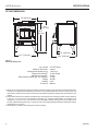
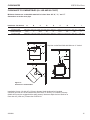
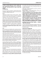
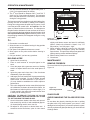
Savannah Small Wood Stove For Residential Installation Model: SSW20 Homeowner's Manual 6" (152 mm) Flue Required 634001 SSW20 cover SAFETY NOTICE: Read this entire manual before you install and use your appliance. If not properly installed, a house fire may result. To reduce the risk of fire, follow the installation instructions. Failure to follow instructions may result in property damage, bodily injury, or even death. Contact local building, fire officials or authorities having jurisdiction about permits, restrictions and installation inspection requirements in your area. These units are mobile home approved for U.S. and Canada 63D4001 8/13 Rev. 10 SSW20 Wood Stove WELCOME Congratulations on your choice of a Vermont Castings Savannah. With this purchase, you made a commitment to make the hearth a place of warmth, beauty and comfort in your home. At Vermont Castings, we share that joy and appreciation of the hearth, and we show it in all our cast iron stoves and fireplaces. As you become acquainted with your new stove, you will find the aesthetic appeal of cast iron is matched only by its superb capacity to absorb and radiate heat. Also, Vermont Castings products are among the cleanest burning wood stoves and fireplaces available today. As an owner of a Vermont Castings stove, you are making a strong statement for pollution-free energy. But clean burning depends on both the manufacturer and the operator. Please read this manual carefully to understand how to properly operate your stove. At Vermont Castings, we are equally committed to your satisfaction as a customer and that is why we maintain an exclusive network of the finest dealers in the industry. Chosen for their expertise and dedication to customer service, our dealers are factory-trained and know each Vermont Castings product in detail. Feel free to contact your Authorized Vermont Castings Dealer anytime you have a question about your stove or its performance. We have built your stove with the utmost care. With normal use and proper care, it will provide you with many years of service. This manual contains valuable instructions on the installation and operation of your Vermont Castings stove. You will also find useful information on assembly and maintenance procedures. We urge you to read the manual thoroughly and to keep it as a reference. Sincerely, All of us at Vermont Castings This manual describes the installation, operation, and maintenance of the Vermont Castings Savannah wood burning heater. This heater meets the U.S. Environmental Protection Agency’s emission limits for wood heaters sold on or after July 1, 1990. Under specific test conditions this heater has been shown to deliver heat at rates ranging from 11,000 to 45,000 Btu/hr. The stove has been tested and is listed by OMNI - Test Laboratories, Inc. of Portland, Oregon. The test standards are ANSI/UL-1482 for the United States, and ULC S627 for Canada. The Savannah is listed for burning wood only. Do not burn other fuels. The Savannah is approved for use in manufactured (mobile) homes in the United States and Canada, only when installed with Vermont Castings Mobile Home Kit No. SSWMHIK. Installation or service of this woodburning stove should only be completed by a qualified installer, preferably NFI or WETT (Canada) certified. NOTICE Please read this entire manual before you install and use your new stove. Failure to follow instructions may result in property damage, bodily injury, or even death. Save These Instructions for Future Reference 63D4001 CONTENTS SSW20 Wood Stove INSTALLER OWNER Please leave these instructions with the appliance. Please retain these instructions for future reference. IMPORTANT Read these instructions carefully before installing or trying to operating this woodburning appliance. TABLE OF CONTENTS ACCESSORIES Accessories................................................................... 3 Safety Information......................................................... 4 Installation Information.................................................. 5 Stove Dimensions and Specifications........................... 6 Stove set-up.................................................................. 7 Installation..................................................................... 8 Clearances.................................................................. 15 Operation..................................................................... 16 Maintenance................................................................ 17 Replacement parts...................................................... 20 FAQs........................................................................... 21 Warranty...................................................................... 23 Variable Speed Blower Outside Air Termination Kit Mobile Home Installation Kit Universal Gasket Kit WARNING Proposition 65 Warning Fuels used in gas, woodburning or oil fired appliances, and the products of combustion of such fuels, contain chemicals known to the State of California to cause cancer, birth defects and other reproductive harm. ! BLOTWS SSWOATK SSWMHIK SSWUGK WARNING HOT GLASS WILL CAUSE BURNS. DO NOT TOUCH GLASS UNTIL COOLED. NEVER ALLOW CHILDREN TO TOUCH GLASS. California Health and Safety Code Sec. 25249.6 Need to ask questions? Require Parts Information? First, contact the Vermont Castings Dealer from whom you purchased your stove, for parts and service. Have the following information ready: • Date of purchase • Serial number (from the back of your stove) • Model number (from the back of your stove) • Dealer name and phone If you still need assistance, contact Vermont Castings technical support (below). Wondering about the warranty? See the last page of this manual for general warranty information. For additional information, contact your Vermont Castings dealer or Vermont Castings Parts and warranty. Vermont Castings Technical Service, Parts & Warranty Phone: 877-406-9180 Fax: 877-406-5647 Model and product serial numbers can be found on the certification label of your stove. 63D4001 SSW20 Wood Stove SAFETY INFORMATION Please Read This Manual Before Installing and Using Fireplace IMPORTANT: Read all instructions and warnings carefully before starting installation. Failure to follow these instructions may result in a possible fire hazard and will void the warranty. SAFETY NOTICE: IF YOUR STOVE IS NOT PROPERLY INSTALLED, OPERATED AND MAINTAINED, A HOUSE FIRE MAY RESULT. FOR SAFETY, FOLLOW ALL INSTALLATION, OPERATION AND MAINTENANCE DIRECTIONS. CONTACT LOCAL BUILDING OFFICIALS ABOUT RESTRICTIONS AND INSTALLATION INSPECTION REQUIREMENTS IN YOUR AREA. This stove is HOT WHILE IN OPERATION! KEEP CHILDREN, CLOTHING AND FURNITURE AWAY. CONTACT MAY CAUSE SKIN BURNS. Precautions WARNING: Operate only with doors fully closed. If doors are left partly open, gas and flame may be drawn out of the stove opening, creating risks of both fire and smoke. Vermont Castings stoves and component parts have been tested to operate safely when installed in accordance with instructions provided in this manual. Carefully read and understand all instructions before beginning installation. If you notice any damage to stove or component parts, immediately report damage to your Vermont Castings dealer. Only use Vermont Castings components or the warranty will be voided and a fire hazard may be created. Vermont Castings warranty will be voided by and Vermont Castings disclaims any responsibility for the following actions: • Installation of any damaged stove or chimney • • • component; Modification of stove, chimney assembly or any component parts thereof; (except for chase flashings as detailed in Vermont Castings Chimney Top installation instructions). Installation other than as instructed by Vermont Castings; or Installation and/or use of any component part not manufactured or approved by Vermont Castings in combination or assembly with a Vermont Castings stove system, notwithstanding any independent testing laboratory or other third party approval of such component parts or accessory. Any such action may possibly cause a fire hazard. Consult local building codes to ensure that you are in compliance before installing the stove. This stove and chimney system must be vented outdoors. Do not obstruct or modify air inlets/outlets in any manner. Burn only solid wood fuel. The stove is intended for operation only with the door fully closed. Do not install any products not specified for use with this stove. DO NOT OVERFIRE THIS HEATER. Overfiring can result in permanent damage to the stove. If an exterior part of the stove or the chimney connector glows, you are overfiring. BEFORE INSTALLATION OF YOUR APPLIANCE 1. Check with the building inspector’s office for compliance with local codes; a permit may be required. 2. This appliance requires a masonry or prefabricated chimney listed to ULC S629 (Canada) and UL 103HT (U.S.) sized correctly. 3. A 6" (152 mm) diameter flue is required for proper performance. 4. Always connect this unit to a chimney and NEVER VENT TO ANOTHER ROOM OR INSIDE A BUILDING. 5.DO NOT connect this unit to any duct work to which another appliance is connected such as a furnace. 6.DO NOT connect this unit to a chimney flue serving another appliance. 7. The connector pipe and chimney should be inspected periodically and cleaned if necessary. 8. Remember the clearance distances when you place furniture or other objects within the area. DO NOT store wood, flammable liquids or other combustible materials too close to the unit. Refer to certification label on back of your unit for required clearances. 9. Contact your local municipal or provincial fire authority for information on how to handle a chimney fire. Have a clearly understood plan to handle a chimney fire. In the event of a chimney fire, turn air control to closed position and CALL THE FIRE DEPARTMENT. 10.DO NOT tamper with combustion air control beyond normal adjustment. 11. If installing in a mobile home: a. Use mobile home kit. b. WARNING: DO NOT install in sleeping room. c. The structural integrity of the mobile home floor, walls and ceiling/roof must be maintained. 63D4001 INSTALLATION INFORMATION SSW20 Wood Stove Should you experience such a problem call in a local chimney expert. With the door closed, the rate of burning is regulated by the amount of air allowed to enter the unit through the air control. With experience you will be able to set the control for heat and burning time desired. Once the required chimney draft is obtained, operate only with doors closed and open slowly when re-fueling. (This will reduce or eliminate smoke from entering the room.) Attempts to achieve higher output rates that exceed heater design specifications can result in permanent damage to the heater. The recommended wood load is level with the top of the firebricks. Overloading may prevent sufficient air entering the heater to properly fuel the fire. Important: For optimum heater performance at “low” burn rate, operate the fan at low speed. An outside air kit is available from your Vermont Castings dealer. Optional Blower: 110v 130 CFM Model: BLOTWS • OPERATE THIS HEATER ONLY WITH THE DOOR • • CLOSED. DO NOT BURN GARBAGE OR FLAMMABLE FLUIDS. DO NOT USE CHEMICALS OR FLUIDS TO START THE FIRE. 63D4001 CAUTION Today’s solid fuel appliances are much more efficient than in the past. The units are designed to give you controlled combustion, as well as maximum heat transfer, using less fuel to do so. The design of your new appliance is such that the exhaust “smoke” is now at lower temperatures than in the past, therefore requiring proper chimney size to give adequate draft. If your chimney is too large, the heating appliance will have a difficult time to raise the “chimney flue” temperature to give adequate draft, therefore causing a smoke back up, poor burn, or both. DANGER Draft is the force, which moves air from the appliance up through the chimney. The amount of draft in your chimney depends on the length of the chimney, local geography, nearby obstructions, and other factors. Too much draft may cause excessive temperatures in the appliance. An uncontrolled burn, a glowing red part or chimney connector indicates excessive draft. Inadequate draft may cause back puffing into the room and “plugging” of the chimney and/or cause the appliance to leak smoke into the room through appliance and chimney connector joints. CAUTION WHY THE CORRECT FLUE SIZE IS IMPORTANT — 6" (152 mm) After reading these instructions, if you have any doubt about your ability to complete your installation in a professional manner, you should obtain the services of an installer versed in all aspects of correct and safe installation. DO NOT use temporary, makeshift compromises during installation. THIS HEATER IS EXTREMELY HOT WHILE IN OPERATION. SERIOUS BURNS CAN RESULT FROM CONTACT. KEEP CHILDREN, PETS, CLOTHING AND FURNITURE AWAY RISK OF ELECTRIC SHOCK. DISCONNECT POWER BEFORE SERVICING UNIT. Avoid Damaging the Glass Door Panel Do not abuse the glass by slamming the door or striking the glass with a log. Never operate your stove if it has damaged or broken glass. If you need to replace the glass, use only replacement glass provided by your Vermont Castings dealer. MATERIALS NEEDED FOR INSTALLATION: • Adjustable wrench • Flat & Phillips screwdriver • Drill • Tape measure • Safety gloves • Eye protection • Appropriate venting components • Furnace cement SPECIFICATIONS SSW20 Wood Stove Stove dimensions 25” (635 mm) 306M” (781 mm) 286M” (730 mm) 2156O” (546 mm) 19” (483 mm) 2456O” (622 mm) Figure 1 Savannah Dimensions 634001 SSW20 dims Log Length Maximum burn time2 Average area heated (sq.ft)2 Range of heat output3 Maximum heat output1 EPA emissions rating (g/h, non-catalytic) Weight Loading Air Control 18" (457 mm) 8 hours 1,000 sq. ft. 11,000-45,000 46,000 3.7 gph 400 lbs Front Manual 1.Maximum burn times and heat outputs are based on laboratory testing using full loads of seasoned hardwoods, and may vary in individual use depending on how the stove is operated, type and moisture content of fuel, and other factors. Maximum burn times are achieved under different operating conditions than are maximum heat outputs. 2.These values are based on operation in building code-conforming homes under typical winter climate conditions in the U.S. If your home is of nonstandard construction (e.g. unusually well-insulated, not insulated, built underground, or if you live in a more severe and more temperate climate), these figures may not apply. Since so many variables affect performance, consult your Vermont Castings Authorized Dealer to determine realistic expectations for your home. 3.Under specific conditions used during EPA emissions testing. 63D4001 INSTALLATION safety NOTICE: IF YOUR stove IS NOT PROPERLY INSTALLED, A HOUSE FIRE MAY RESULT. TO REDUCE THE RISK OF FIRE, FOLLOW THE INSTALLATION INSTRUCTIONS. CONTACT LOCAL BUILDING OR FIRE OFFICIALS ABOUT RESTRICTIONS AND INSTALLATION INSPECTION REQUIREMENTS IN YOUR AREA. Before you begin an installation, review your plans to see that: • Your stove and chimney connector will be far enough from combustible material to meet all clearance requirements. • The floor protector is large enough and is constructed properly to meet all requirements. • You have all necessary permits from local authorities. Your local building official is the final authority for approving your installation as safe and determining that it meets local and state codes. The metal label permanently attached to the back of every Vermont Castings stove indicates the stove has been tested to current standards. The test standards are ANSI/UL-1482 for the United States and ULCS627 for Canada. Clearance and installation information also is printed on the label. When the stove is installed according to the information both on the label and in this manual, local authorities in most cases will accept the label as evidence that the installation meets codes and can be approved. However, codes vary in different areas. Before starting the installation, review your plans with the local building authority. You local dealer can provide any additional information needed. For any unresolved installation issues, refer to CSA CANB365 Installation Code for Solid Fuel Burning Appliances and Equipment. These standards are the basis for many national codes. They are nationally recognized and are accepted by most local authorities. Your local dealer or your local building official may have a copy of these regulations. Important: Failure to follow these installation instructions may result in a dangerous situation, including a chimney or house fire. Follow all instructions exactly, and do not allow makeshift compromises to endanger property and personal safety. Outside Air In some modern, super-insulated homes, there is not enough air for combustion because of insufficient air infiltration into the building. Such air enters a home through unsealed cracks and openings. Kitchen or bath exhaust fans can compete with the stove for available air and compound the problem. 63D4001 SSW20 Wood Stove When poor draft is caused by a low infiltration rate, opening a ground floor window on the windward side of the house and in the vicinity of the stove will usually alleviate the problem. Another solution is to install a permanent outside air supply to the stove and/or room. In some areas, in fact, bringing air for combustion from outside the home directly to the air inlet of the stove is required for new construction. An outside air supply is not affected by pressure variations within the house, and improved stove performance often results. An Outside Air Adaptor Kit for the Savannah is available from your local Vermont Castings dealer. NOTE: For Canada installations, if an outside air adapter kit is used, the appliance must be secured directly to the floor of the home structure. STOVE SET-UP 1. Check that all brick and tubes are in place. 2. Select the proper location for the stove. These appliances must not be installed any closer than the minimum clearance to combustible materials shown on Page 15 of this manual. The stove must be installed on a non-combustible surface as shown on Page 13 of this manual. 3. Remove packing material and packing labels from glass. FAILURE TO FOLLOW THE MINIMUM CLEARANCE REQUIREMENT AND NON-COMBUSTIBLE SURFACE REQUIREMENTS MAY RESULT IN AN UNSAFE INSTALLATION 4. If non-combustible materials have been installed on the walls, obtain the minimum clearances from either the manufacturer of these materials or the local building inspectors office. 5. Install the stovepipe INSIDE the flue collar on the top of the stove between the stove and chimney. 6.DO NOT use a grate to elevate the fire. STOVE PIPE 1. Make sure your chimney and chimney connector meets safety codes. Check with authorities having jurisdiction in your area. 2. All pipe sections must be connected with the male end (crimped end) toward the stove. 3. Fasten the stove pipe to the flue collar by the use of three sheet metal screws. Do the same at each additional joint to make the entire installation rigid. 4. Maintain the required diameter flue for the entire installation. installation SSW20 Wood Stove 5. If you are connecting the stove to an old masonry flue, be sure to have it inspected for cracks and general condition. Resizing with a stainless steel liner may be required. 6. It is recommended that no more than two 90 degree bends be used in the stovepipe installation. More than two 90 degree bends may decrease the amount of draw and possible cause smoke spillage. 7. A damper is not required in this installation. Remove any damper plate in the chimney or secure in the OPEN position. 8. Single wall flue pipe assemblies must not exceed 10 feet (3 meters) in overall length. It is common for a masonry flue to be oversized for the stove. Such a chimney can take quite a while to warm up, and the stove performance will likely be disappointing. The best solution to an oversize flue problem is the installation of an insulated steel chimney liner of the same diameter as the appliance flue outlet. The liner keeps the exhaust gas warm and the result is a stronger draft. An uninsulated liner is a second choice—although the liner will keep the exhaust restricted to its original volume, the air around the liner will require time and heat energy to warm up. Notes on Chimney and Stovepipe Insulation: Although masonry is the traditional material used for chimney construction, it can have distinct performance disadvantages when used to vent a controlled combustion wood stove. Masonry forms an effective “heat sink”—that is, it absorbs and holds heat for long periods of time. Maintaining a clean chimney is important. Chimneys should be inspected regularly for creosote buildup. A straight chimney is easier to clean than one with 45 or 90 degree bends. A bend requires the pipe to be removed for cleaning. The stove baffle must be removed when cleaning the chimney (Refer to Page 18). Chimney sweepings will build up on top of baffle causing a blocked flue and/or a fire hazard. Steel Chimney Most factory made “Class A” steel chimneys have a layer of insulation around the inner flue. This insulation keeps the smoke warm and protects the surrounding structure from the high flue temperatures. Because the insulation is less dense than masonry, the inner steel liner warms up more quickly than masonry chimney; this makes the steel chimney support a good draft more quickly than masonry does. Indoor/Outdoor Location Because the chimney’s function is to keep the smoke warm, it is best to locate it inside the house. This location uses the house as insulation for the flue and allows some radiant heat release form the flue into the home. Since an interior chimney doesn’t continuously lose its heat to the outdoors, less heat from the stove is required to get it warm and keep it warm. Flue Sizing The flue size for a controlled-combustion appliance should be based on the cross-sectional volume of the stove flue outlet. In this case, more is definitely not better. Hot gases lose heat through expansion; if a stove with a six-inch flue collar (28 square inch area) is vented into a 10" x 10" flue, the gases will expand to over three times their original volume. As gases cool with expansion, draft strength decreases. If the oversized flue is also outside the house, the heat it absorbs will be conducted to the outdoor air and the flue will remain relatively cool. Check your local codes. You may be required to install a flue liner in any oversize masonry flue. Masonry Chimney The large mass however, may take a long time to become hot enough to sustain a strong draft. The larger the chimney (in total mass) the longer it will take to warm up. Cold masonry will actually cool exhaust gases enough to diminish draft strength. This problem is worse if the chimney is located outside the home or if the chimney flue has a cross-sectional volume much larger than the stove outlet. Pipe and Chimney Layout Every bend in the flue will act as a brake on the exhaust as it flows from the firebox to the chimney cap. The ideal pipe and chimney layout is straight up from the stove through completely straight chimney. Use this layout if at all possible, as it will promote optimum stove performance and simplify maintenance. If the stovepipe must elbow to enter a chimney, locate the elbow about midway between the stovetop and the chimney thimble. This configuration lets the smoke speed up before it must turn, keeps some pipe in the room for heat transfer, and allows long-term flexibility for installing a different appliance without relocating the thimble. There should be no more than eight feet of single-wall stove pipe between the stove and a chimney. Longer runs can cool the smoke enough to cause draft and creosote problems. Use double-wall stove pipe for longer runs. Single Venting Your stove requires a dedicated flue. Do not connect the stove to a flue used by any other appliance. Chimney draft is a natural form of energy and follows the path of least resistance. If the stove is vented to a flue that also serves open replace or another appliance, the draft will also pull air through those avenues. The additional airflow will lower the flue temperatures, reduce draft strength and promote creosote development; overall stove performance will suffer. The effect is similar to 63D4001 installation SSW20 Wood Stove that of a vacuum cleaner with a hole in the hose. In some extreme instances, the other appliances can even impose a negative draft and result in a dangerous draft reversal. CHIMNEY Refer to chimney and chimney connector manufacturer’s instructions. Contact your local building authority for approved methods of installation 1. This appliance requires a masonry or pre-manufactured chimney listed to ULCS629 (Canada) and UL 103 HT (USA) sized correctly. 2. If a masonry chimney is used it is advisable to have your chimney inspected for cracks and check the general condition before you install your unit. Re-lining may be required to reduce flue diameter to the appropriate functional size. 3. The chimney should extend at least 3' (914 mm) above the highest point where it passes through the roof, and at least 2' (610 mm) higher than any portion of a building within 10' (3 m). Figure 2 4. The chimney connector shall not pass through an attic, roof space, closet, concealed space, floor, ceiling, wall or any partition of combustible construction. 5. The minimum overall height of your chimney should be 15' (5 m) from the floor. 6. D o n o t u s e m a k e s h i f t c o m p r o m i s e s d u r i n g installation. 0 to 10’ 2’ Min. 0 to 10’ 2’ Min. 3’ Min. ST1012 Figure 2 ST1012 The 2'-3'-10' Chimney Rule 2 3 10 rule At the very least, inspect the chimney connector and chimney at least once every two months during the heating season to determine if a buildup of creosote or soot has occurred. If a significant layer of creosote has accumulated (1/8" (3 mm) or more], or if soot has accumulated, either should be removed to reduce the risk of a chimney fire. Failure to keep the chimney and connector system clean can result in a serious chimney fire. 63D4001 To reduce the amount of creosote that may form, remember to provide adequate air for combustion and to strive for small, intense fires rather than large smoldering ones. You can never be too safe. Contact your local fire authority for information on what to do in the event of a chimney fire, and have a clearly understood plan on how to handle one. Chimney Connector Guidelines Chimney connector is the double-wall or single-wall pipe that connects the stove to the chimney. The chimney is a masonry or prefabricated structure that encloses the flue. Chimney connectors are used only to make the connection from the stove to the chimney. Double-wall chimney connectors must be tested and listed for use with solid-fuel burning appliances. Singlewall chimney connectors should be made of 24 gauge or heavier steel, and should be 6” (150 mm) in diameter. Do not use galvanized connector; it cannot withstand the high temperatures that can be reached by smoke and gases, and may release toxic fumes under high heat. If possible, do not pass the chimney connector through a combustible wall or ceiling. If passage through a combustible wall is unavoidable, refer to the section following on Wall Pass-Throughs. Do not pass the chimney connector through an attic, a closet, or any similar concealed space. The whole connector should be exposed and accessible for inspection and cleaning. 3’ Min. Reference Point The conditions for a chimney fire develop as follows: When wood is burned slowly, it produces tar and other organic vapors which combine with expelled moisture to form creosote. The creosote vapors condense in the relatively cool chimney flue of a slow burning fire. As a result creosote residue accumulates on the flue lining. Creosote is a flammable and, when ignited, make an extremely hot fire within the flue system which can damage the chimney and overheat adjacent combustible material. In horizontal runs of single-wall chimney connector without protective shields, maintain a clearance of at least 26” (660 mm) from the ceiling. For information on reduced clearances using shields on single-wall chimney connector or using double-wall connectors, see the clearance chart on Page 15. Keep the horizontal run of chimney connector as short and direct as possible, with no more than two 90° turns. Slope horizontal runs of connector upward 1/4” per foot (20 mm per m) going from the stove toward the chimney. The recommended maximum length of a horizontal run is 3’ (914 mm). The recommended total length of chimney connector is 8’ (2.4 m). In cathedral ceiling installations, extend the prefabricated chimney down to within 8’ (2.4 m) of the stove. installation SSW20 Wood Stove SAFETY NOTE: Always wear gloves and protective eyewear when drilling, cutting or joining sections of chimney connector. Double-wall Chimney Connector The listing for the Savannah for the U.S. and Canada includes use of double-wall chimney connectors that have been tested and listed for use with solid-fuel burning appliances by a recognized testing laboratory. Information on assembling and installing double-wall connector is provided by the manufacturer of the double-wall pipe. Follow the manufacturer’s instructions exactly as you assemble the connector and attach it to the stove and chimney. Using connectors and chimneys from the same manufacturer makes the assembly and installation straightforward. NOTE: For installations using double-wall connectors, minimum clearances must conform to the listed clearances in the clearance chart on Page 14. Single-wall Chimney Connector • Beginning at the flue collar of the stove, assemble the chimney connector. Insert the first crimped end into the stove’s flue collar, and keep each crimped end pointing toward the stove. Using the holes in the flue collar as guides, drill 1/8” (3 mm) holes in the bottom of the first section of chimney connector and secure it to the flue collar with three #10 x 1/2” sheet metal screws. • Secure each joint between sections of chimney connector, Figure 3 including telescoping joints, Chimney Connector with at least three sheet metal ST242 Chimney connector screws. The pre-drilled holes 12/13/99 djt in the top of each section of chimney connector serve as guides when you drill 1/8” (3 mm) holes in the bottom of the next section. • Secure the chimney connector to the chimney. Instructions for various installations follow. • Be sure the installed stove and chimney connector are correct distances from nearby combustible material. NOTE: Special slip pipes and thimble sleeves that form telescoping joints between sections of chimney connector are available to simplify installations. They often eliminate the need to cut individual connector sections. Consult your local dealer about these special pieces. 10 Secure the Single-wall Connector to a Prefabricated Chimney For prefabricated chimneys, follow the installation instructions of the chimney maker exactly as you install the chimney. The maker of the chimney will supply the accessories to support the chimney, either from the roof of the house, at the ceiling of the room where the stove is installed, or from an exterior wall. Special adapters are available from your local dealer to make the connection between the prefabricated chimney and the chimney connector. The top of such adapters attaches directly to the chimney or to the chimney’s ceiling support package, while the bottom of the adaptor is screwed to the chimney connector. These adapters are designed so the top end will fit outside the inner wall of the chimney, and the bottom end will fit inside the first section of chimney connector. When assembled in this way, any soot or creosote falling from the inner walls of the chimney will stay inside the chimney connector. Secure the Single-wall Connector to a Masonry Chimney For masonry chimneys, both freestanding and fireplace chimneys may be used for installation of your stove. Thimble Sleeve Flue Chimney Connector Keep sleeve end flush with flue tile Figure 4 Chimney Connector Thimble Sleeve ST243 Freestanding Chimney Installations If the chimney connector must pass through a combustible wall to reach the chimney, follow the recommendations in the Wall Pass-through section that follows. ST243 thinble The opening through theconnection chimney wall to the flue (the 12/13/99 djt a ceramic or metal cylin“breach”) must be lined with either der, called the “thimble”, which is cemented firmly in place. The fit must be snug and the joint between the thimble and the chimney wall must be cemented. Figure 5 A special piece called the “thimble sleeve,” slightly smaller in diameter than standard connector and most thimbles, will facilitate the removal of the chimney connector system for inspection and cleaning. Thimble sleeves should be available from your local dealer. Figure 4 63D4001 installation SSW20 Wood Stove Chimney Flue Elbow Flue Liner Chimney Connector Shields * Slip Pipe Thimble Standard Chimney Connector * Check These Clearances * Flue Collar Mantel Seal the Damper ST1094 Figure 5 Freestanding Installation Chimney Connection To install a thimble sleeve, slide it into the breach until it is flush with the inner flue wall. Do not extend it into the actual flue passage, as this could interfere with the draft. ST1094 freestanding The thimble sleeve should protrude 1-2” (25-50 mm) into the room. Use furnaceinstallation cement and thin gasketing to seal the sleeve in place in the thimble. Secure the chimney connector to the outer end of the sleeve with sheet metal screws. Without a thimble, a suitable length of chimney connector can be extended through the breach to the inner face of the flue liner, and cemented securely in place. Additional pieces of connector are then attached with sheet metal screws. Fireplace Chimney Installations Above a Fireplace The Savannah may be connected to a chimney above a fireplace opening also. In such installations, the stove is positioned on the hearth in front of the fireplace and the chimney connector rises from the stove top and then angles ninety degrees back into the chimney. Figure 6 The chimney liner should extend to the point at which the chimney connector enters the chimney. If the chimney connector from your installation enters the chimney above a fireplace, follow all the guidelines mentioned above for freestanding installations. In addition, give special consideration to the following points: Figure 6 Chimney Connection Above a Fireplace ST1095 • Check the clearance between the stove and the chimney • • connector, and anyST1095 combustible trim or the mantel. Use the necessary combination mantel, trim, and connecchimney of connector above tor heat shields to fireplace achieve the required clearances. Check the clearance between the chimney connector and the ceiling. If no heat shields are used, the clearance should be at least 26” (660 mm). To find out how much this clearance may be reduced with heat shields, see the clearance chart on Page 15. The fireplace damper must be sealed to prevent room air from escaping up the flue. However, it must be possible to re-open the damper to inspect or clean the chimney. Fireplace Chimney Installations Through a Fireplace If your fireplace height is at least 25” (635 mm), you may install an Savannah with standard legs through the fireplace opening using a “positive connection” kit available from your local dealer. These positive connection kits ensure a tight fit between the stove flue collar and the chimney flue. Figure 7. Fireplace installations, whether connected to the flue above or through the fireplace opening, have special clearance requirements to adjacent trim and the mantel. You’ll find the required clearances for the Savannah fireplace installations on Page 15. Floor protection requirements also apply to fireplace installations. Floor protection information is on Page 15. 63D4001 11 installation SSW20 Wood Stove • Placing a section of chimney connector inside a section of 9” (230 mm) diameter, solid-insulated, factory-built chimney, with 2” (50 mm) of air space between the chimney section and combustibles. Wall Stud Flexible Connector Chimney Connector Mantel Shield Fireplace Adaptor Kit T 12” of Noncombustible Material ST1096 Figure 7 Chimney Connector Through a Fireplace Wall Pass-Throughs ST1096 Whenever possible, design your installation so the connecchimney thru fireplace tor does not pass through a combustible wall. If you are considering a wall pass-through in your installation, check with your building inspector before you begin. Also, check with the chimney connector manufacturer for any specific requirements. Accessories are available for use as wall pass-throughs. If using one of these, make sure it has been tested and listed for use as a wall pass-through. In the United States, the National Fire Protection Association (NFPA) has established guidelines for passing chimney connectors through combustible walls. Many building code inspectors follow these guidelines when approving installations. Figure 8 shows one NFPA-recommended method. All combustible material in the wall is cut away from the single-wall connector to provide the required 12” (305 mm) clearance. Any material used to close up the opening must be noncombustible. Three other methods are also recommended by NFPA: • Using a section of double-wall chimney with a 9” (230 mm) clearance to combustibles. • Placing a section of chimney connector inside a ventilated thimble, which in turn is separated from combustibles by 6” (150 mm) of fiberglass insulating material. 12 ST1097 Floor Protection Figure 8 A Brick Pass thru - Approved In the United States In Canada, The Canadian Standards Association has established installation guidelines. The following illustration shows one method, in which all combustible material in the wall is cut away to provide the required 18” (460 mm) clearance for the connector. The resulting space must remain ST1096 empty. A flush-mounted sheet metal cover may be used Brick pass thru on one side only. If covers must be used on both sides, each cover must be mounted on noncombustible spacers at least 1” (25 mm) clear of the wall. Your local dealer or your local building inspector can provide details for other approved methods of passing a chimney connector through a combustible wall in your area. In Canada, this type of installation must conform to CAN/CSA-B365, Installation Code for Solid Fuel Burning Appliances and Equipment. Note: Do not vent your Savannah into a factory-built (zero-clearance) fireplace. These appliances and their chimneys are specifically designed as a unit for use as fireplaces. It may void the listing or be hazardous to adapt them for any other use. Do not connect AN Savannah to any air distribution duct or system. 63D4001 installation SSW20 Wood Stove E 18" (450 mm) Empty Space All Around the Chimney Connector E D B D D ST1010 C Sheet Metal Cover (This Side Only) Figure 9 Hollow wall pass-thru ST1010 Floor Protection hollow wall pass thru A tremendous amount of heat radiates from the bottom plate of your stove. The floor area directly under and around the stove will require protection from radiant heat as well as from stray sparks or embers that may escape the firebox. Spark, ember and thermal protection must be provided by a floor protector constructed with noncombustible material as specified. Special protection for the floor beneath the stove must be provided. Use an approved 1” (25 mm) noncombustible hearth pad with K = 0.84 BTU/in ft2 hr °F or an equivalent material with an R-value of at least 1.19. (Refer to “How to Determine if Alternate Floor Protection Materials are Acceptable” section) The floor protector may be covered with a decorative noncombustible material if desired. Do not obstruct the space under the heater. A ST1059 US Canada A. 41” 41” (1016 mm) B. 45” 47” (1194 mm) C. 16” 18” (457 mm) ST1059 D. 8” 8” (203 mm) SSW20 floor protection E. 2” 2” (51 mm) Figure 10 Installation on a Combustible Floor How to Determine if Alternate Floor Protection Materials are Acceptable All floor protection must be noncombustible (i.e. metals, brick, stone, mineral fiber boards, etc.). Any organic materials (i.e. plastics, wood paper products, etc.) are combustible and must not be used. The floor protection specified includes some form of thermal designation such as R-value (thermal resistance) or k-factor (thermal conductivity). Procedure: 1. Convert specifications to R-value: i. R-value given - no conversion needed. ii. k-factor is given with a required thickness (T) in inches: Protection requirements vary somewhat between the United States and Canada as follows: iii. K-factor is given with a required thickness (T) in inches: U.S. Installations: The floor protector is required under the stove and must extend at least 16” from the front of the stove, and at least 8” from the sides and rear. Figure 10 iv. r-factor is given with a required thickness (T) in inches: R = r x T 2. Determine the R-value of the proposed alternate floor protector: i. Use the formula in Step 1 to convert values not expressed as R. ii. For multiple layers, add R-values of each layer to determine overall R-value. In Canada: a noncombustible floor protector is required under the heater also. The floor protector must extend 18” (457 mm) from the front of the stove, and at least 8” (203 mm) from the sides and rear. Figure 10 63D4001 13 installation SSW20 Wood Stove 3. If the overall R-value of the system is greater than the R-value of the specified floor protector, the alternate is acceptable. EXAMPLE: The specified floor protector should be 3/4-inch thick material with k-factor of 0.84. The proposed alternate is 4” brick with an r-factor of 0.2 over 1/8” mineral board with a k-factor of 0.29 Fireplace installations also have special clearance requirements to the side walls, side decorative trim, and fireplace mantle. Refer to the information on fireplace and mantel trim shields in this section. Step a: Use formula above to convert specification to Rvalue: Step b: Calculate R of proposed system. 4” brick of r = 0.2, therefore: Rbrick = 0.2 x 4 = 0.8 1/8” mineral board of k = 0.29, therefore Rmineralboard = x 0.125 = 0.431 Rtotal = Rbrick + Rmineralboard = 0.8 + 0.431 = 1.231 Step c: Compare proposed system Rtotal of 1.231 to specified R of 1.19. Since proposed system Rtotal is greater than required, the system is acceptable. Definitions R= (ft2)(hr)(°F) Btu k= (Btu)(in) = K x 12 (ft2)(hr)(°F) K = (Btu)(ft) (ft2)(hr)(°F) r= (ft2)(hr)(°F) 1 = (Btu)(in) k ST1098 Wood framing requires protection from radiant heat Figure 11 Supporting timbers under fireplace hearth are considered to be combustible Keep the Stove and Connector a Safe Distance from Surrounding MaST1098 terials floor install Do not assume your fireplace hearth is completely noncombustible. Both a stove and its chimney connector radiate heat in all directions when operating, and dangerous overheating of nearby combustible materials can occur if they are too close to the heat. A safe installation requires that adequate clearance be maintained between the hot stove and its connector and nearby combustibles. Many fireplace hearths do not satisfy the “completely noncombustible” requirement because the brick or concrete in front of the fireplace opening is supported by heavy wood framing as in Figure 11. Because heat passes through brick or concrete readily, it can easily pass through to the wood. As a result, such fireplace hearths can be a fire hazard and are considered a combustible floor. Clearance is the distance between either your stove (measured from the back edge of the stove’s top plate) or chimney connector, and nearby walls, floors, the ceiling, and any other fixed combustible surface. Your stove has special clearance requirements that have been established after careful research and testing to UL and ULC standards. These clearance requirements must be strictly observed. Keep in mind that many raised hearths will extend less than the required clearance from the front of the heater when it is installed. In such cases, sufficient floor protection as described above must be added in front of the hearth to satisfy the minimum floor protector requirement from the front of the stove: 18” (460 mm) from the front in Canada. Fireplace hearths must also offer the required protection of 8” (203 mm) on either side. In addition, furnishings and other combustible materials must be kept away from the stove as well. In general, a distance of 48” (1220 mm) must be maintained between the stove and moveable combustible items such as drying clothes, furniture, newspapers, firewood, etc. Keeping those clearance areas empty assures that nearby surfaces and objects will not overheat. Floor Protection for Fireplace Installations Optional 3” (76 mm) short legs may be used only on such hearths that meet the width and depth requirements outlined previously under “floor protection.” Hearth rugs do not satisfy the requirements for floor protection. 14 63D4001 CLEARANCES SSW20 Wood Stove Clearance to Combustibles (UL-1482 and ULC-s627) Minimum clearance to combustible materials in inches. Note: All “A,” “C,” and “F” dimensions are to the stove pipe. Installation: Full Vertical AB CD E FGH I Single Wall Pipe 15Z\v" 11" 24Z\v" 15" 9" 17Z\x" 50" 18" 11" Flat top model (387 mm) (279 mm) (616 mm)(381 mm) (229 mm) (445 mm) (1270 mm) (457 mm) (279 mm) Double Wall Pipe 11Z\v" 7" 24Z\v" 15" 9" 17Z\x" 50" 18" 7" Flat top model (286 mm) (178 mm) (616 mm)(318 mm) (229 mm) (445 mm) (1270 mm) (457 mm) (178 mm) B A Top Vent out the Back Wall with Minimum 2' Vertical C D G E F H I F E ST1008 Figure 12 Clearances to Combustibles Installation: Alcove—Six inch (6") (152 mm) diameter listed double wall air insulated ST1008 connector pipe with UL 103 HT listed factory-built Class SSW40 “A” chimney, or a masonry chimney. clearances (Mobile home must be equipped with a spark arrestor). Maximum depth of alcove shall be no 10/08 more than 48" (1220 mm). Please refer to NFPA 211. 63D4001 15 OPERATION SSW20 Wood Stove WARNING: Operate only with doors fully closed. If doors are left partly open, gas and flame may be drawn out of the stove opening, creating risks of both fire and smoke. OPERATION Do not use a grate or elevate fire. Build wood fire directly on firebrick. When the stove is used for the first time the solvents in the paint will smoke off. Wood This heater is designed to burn natural wood only. Higher efficiencies and lower emissions generally result when burning air dried seasoned hardwoods, as compared to softwoods or to green or freshly cut hardwoods. Only use dry seasoned wood. Green wood, besides burning at only 60 percent of the fuel value of dry wood, deposits creosote on the inside of your stove and along the chimney. This can cause an extreme danger of chimney fire. To be called “seasoned,” wood must be dried for a year. Regardless of whether the wood is green or seasoned, it should be stored in a well-sheltered ventilated area to allow proper drying during the year to come. Wood should be stored beyond recommended clearance from combustibles. Fuel Even the best stove installation will not perform well with poor fuel. If available, always use hardwood that has been air-dried (seasoned) 12-18 months. Softwood burns more rapidly than hardwood and has a high pitch content that can result in creosote. Decayed wood of any type has little heat value and should not be used. Unseasoned (green) wood has a high moisture content. Much of its heat value will be used to evaporate moisture before the wood can burn. This significantly reduces the amount of energy available to warm your home, as well as the intensity of the fire and temperature of the exhaust gas. Incomplete combustion and cool flue temperatures promote creosote formation and weak draft. You can judge the moisture content of wood by its appearance and weight or use a commercially available moisture meter for exact measurement. Unseasoned wood will be a third heavier than dry wood. Also look for cracks (checking) in the ends of the log that result from contraction as the wood dries. The longer and wider the cracks are, the dryer the wood is. Creosote Creosote is a by-product of low-temperature stove operation, weak draft or both. It is a tar that results when unburned gases condense inside the flue system at temperatures below 290 degrees F. Creosote is volatile and can generate a chimney fire. All of the installation characteristics that adversely affect chimney draft also promote creosote 16 condensation. Consequently, you can minimize creosote accumulation with an effective chimney design and the use of operational techniques that encourage good draft and complete combustion. Inspect your chimney frequently and clean it whenever accumulation exceeds 1/4". DO NOT BURN: Treated Wood, Solvents, Trash, Coal, Garbage, Cardboard, Colored Papers. CAUTION: BURNING OF ANY MATERIALS OTHER THAN UNTREATED FIREWOOD MAY CREATE TOXIC SMOKE AND/OR CARBON MONOXIDE POISONING. CARBON MONOXIDE IS AN ODORLESS GAS THAT CAN CAUSE PERSONAL INJURY OR DEATH. NEVER USE GASOLINE, GASOLINE-TYPE LANTERN FUEL, KEROSENE, CHARCOAL LIGHTER FLUID, OR SIMILAR LIQUIDS TO START OR “FRESHEN UP” A FIRE IN THIS HEATER. KEEP ALL SUCH LIQUIDS WELL AWAY FROM THE HEATER WHILE IT IS IN USE INSTRUCTION FOR FIRST BURN – CURING THE STOVE PAINT Your stove has been painted with the highest quality stove paint and has special break-in procedures. The heat generated by the normal operation of the stove, will serve to harden the paint. Negative Pressure Good draft also depends on a supply of air to the stove; a chimney can’t pull in more air than is available to it. Sluggish draft results when a house is tight enough to prevent the ready flow of air to the stove, or by competition between the stove and other equipment that sends indoor air outside - especially power-driven equipment like range hoods, exhaust fans, clothes dryers, etc. If the chimney draws well with all other equipment turned off (or sealed, in the case of fireplaces and/or other stoves), then you simply need to be careful with timing the use of the other equipment. Note that negative pressure resulting in inadequate indoor combustion air may trigger nearby smoke detectors. If you need to crack a nearby window or door to enable the chimney to draw well, that’s a sign that you should install an outside-air intake to bring combustion air directly to the stove. Vermont Castings dealers carry adapters to attach to the stove to connect an air duct for outdoor combustion air. Ventilate the house during the first three times the stove is used. The paint on the stove will give off smoke, carbon dioxide and an odor. Without adequate ventilation, concentrations of smoke could irritate, or be upsetting. Open doors and windows and use a fan if necessary. After the initial burns the paint will be cured and there should be no more smoke. Each of the initial burns should be conducted as follows: 63D4001 OPERATION & maintenance SSW20 Wood Stove 1. The first 2 burns should be at approximately 250° F (120° C) for approximately 20 minutes. 2. The 3rd burn should be between 500° F and 700° F (260° to 370° C) for at least 45 minutes. The important fact is the paint should be cured slowly. Avoid hot fires during the curing process. The best way to achieve the first burn is with kindling fires. Prolong the fires as needed by adding more kindling. During the curing process the paint may be gummy. Once cured the paint will remain hard. It is normal to see flat spots on painted surfaces of the stove. The flat spots on the paint surface indicate the hotter surfaces of the stove, and is caused by the heat radiating through the paint. It is also expected that shiny spots caused by friction from the packaging materials, will disappear during the curing of the stove. So . . . 1. Remember to ventilate well. 2. Allow the stove to cure before burning for long periods at high temperatures. 3. Flat spots on the painted surfaces are normal. 4. Shiny spots on the paint surface before burning is normal. 5. Call your dealer if you have any questions. BUILDING A FIRE 1. Open inlet air control fully. 2. Place a small amount of crumpled paper in the stove. 3. Cover the paper with a generous amount of kindling wood in a teepee fashion and a few small pieces of wood. 4. Ignite the paper and close door. If fire dies down substantially, open door slightly. 5. Add larger pieces of wood as the fire progresses being careful not to overload. Do not fill firebox beyond firebrick area. An ideal coal bed of 1" (25 mm) to 2" (51 mm) should be established to achieve optimum performance. 6. This unit is designed to function most effectively when air is allowed to circulate to all areas of the firebox. An ideal means of achieving this is to rake a slight (1" to 2" wide) trough in the center of the coal bed from front to back prior to loading the fuel. CAUTION: TO REDUCE THE RISK OF GLASS BREAKAGE, AVOID LOCATING WOOD FUEL CLOSE TO, OR TOUCHING THE DOOR GLASS. 7. Once fuel has been loaded, close door and open air inlet control fully until fire is well established (approx. 10 minutes) being careful not to over fire. 8. Re-adjust air inlet control to desired burn rate. If excessive smoke fills firebox, open air inlet control 63D4001 A Low Burn High Burn ST1060 Figure 13 Air Control Layout slightly until flames resume and wood is sufficiently ignited. A basic rule of thumb is “closed – low,” "1/2 way-medium,” and “fully open – high.” ST1060 9. When refueling, adjust air control to the fully open SSW20 air control position. When fire brightens, slowly and carefully open the door. This procedure will prevent gases from igniting causing smoke and flame spillage. 10. Add fuel being careful not to overload. 11. Close doors. MAINTENANCE RemovE firebrick To remove firebrick, lift up from bottom and rotate outward. Figure 14 Figure 14 Removing Firebrick Firebrick ST1088 GLASS CARE Avoid Damaging the glass door panST1088 el remove Do not abuse the glass by slamming the firebrick door or striking the glass with a log. Never operate your stove if it has damaged or broken glass. If you need to replace the glass, use only replacement glass provided by your local Vermont Castings dealer. 17 MAINTENANCE SSW20 Wood Stove REPLACE GLASS ONLY WITH HIGH TEMPERATURE CERAMIC AVAILABLE FROM YOUR LOCAL Vermont Castings DEALER The following use and safety tips should be observed: 1. Inspect the glass regularly for cracks and breaks. If you detect a crack or break, extinguish the fire immediately, and contact your dealer for replacement. 2. Do not slam door or otherwise impact the glass. When closing doors, make sure that logs or other objects do not protrude to impact the glass. 3. Do not clean the glass with materials which may scratch (or otherwise damage) the glass. Scratches on the glass can develop into cracks or breaks. 4. Never attempt to clean the glass while unit is hot. Light deposits are normal. Heavier deposits may be removed with the use of a readily available oven cleaner. 5. Never put substances which can ignite explosively in the unit since even small explosions in confined areas can blow out the glass. 6. This unit has an air wash system designed to reduce deposits on glass. GASKET REPLACEMENT After extensive use, the sealing material which provides glass and door seal may need to be replaced if it fails to sustain its resilience. Inspect glass and door seal periodically to ensure proper seal: if gaskets become frayed or worn, replace immediately. Contact your Vermont Castings dealer for approved replacement parts. Refer to replacement parts list in this manual. The following steps should be followed for glass gasket replacement: 1. Ensure appliance is not in operation and is thoroughly cooled 2. Remove door and place on a protected flat surface. 3. Remove screws and glass clips. 4. Lift glass out. 5. Remove old gasket and clean glass. 6. Sand gasket groove and wipe clean (rubbing alcohol works well). 7. Put a thin film of gasket cement on the door. 8. Replace new gasket starting at the top center of the door. 9. Trim to length and butt ends together. Remove all excess cement. 10. Replace glass in door, being sure not to over-tighten screws and clips. The following steps should be followed for door gasket and ash pan door gasket replacement: 1. Ensure appliance is not in operation and is thoroughly cooled. 2. Remove door and place on a protected flat surface. 3. Remove old door gasket and clean channel. 4. Sand gasket groove and wipe clean (rubbing alcohol works well). 5. Using an approved high temperature gasket cement, apply a thin coat in bottom of channel. 6. Starting at top center of door, work into channel around door unit, trim to length and butt ends. 7. Close door and allow three to four hours for cement to set before restarting appliance. removE the baffle To remove the baffle you will have to remove the secondary air tubes and the C-cast baffle plates. Figure 15 1. Use a Philips Secondary Air head screw driv- Tubes C-Cast Baffle er or your fingers to remove the drywall screws that are hanging down next to the secondary air tubes. These screws were for shipping purposes only and can ST1014 Figure 15 be discarded. 2. To remove the ST1014 tubes, start by removing the cotter pin on the left end secondary air tubes of each tube, then slide the tube to the right until the tube can be pulled down and left, and removed from the stove. The four (4) lower tubes are the same. 3. After all four tubes have been removed you can remove the two piece C-cast baffle. Be very careful not to damage the baffle. Carefully lift up on the rear piece and move it as far back as possible letting it sit on top of the steel non-removable baffle. Next, lift up on the front piece and move ST1015 it to the left and alFigure 16 low the right side to ST1015 angle down into the baffle firebox until it can be removed through the door opening. You can now remove the rear piece the same way. Figures 16 and 17 Figure 17 ST1016 ST1016 remove baffle 18 63D4001 MAINTENANCE SSW20 Wood Stove 4. Replace the C-cast baffle and tubes. After the tubes are in place check to see that the c-cast baffle is slid back against the steel non- removable baffle. Replace the rear bricks. Cleaning your chimney The Savannah SSW20 stove has a removable baffle which allows the chimney to be cleaned without removing the connector from the stove. Make sure the stove is cool before proceeding CREOSOTE When wood is burned slowly, it produces tar and other organic vapors. These combine with moisture to form creosote. Creosote vapors condense in the relatively cool chimney flue of a slow burning fire. As a result, creosote residue accumulates on the flue lining. When ignited, this creosote makes an extremely hot fire. The chimney should be inspected regularly during the heating season to determine if a creosote build-up has accumulated. If this is the case, the creosote should be removed to reduce the risk of chimney fire. Warning: Things to remember in case of chimney fire: 1. CLOSE DRAFT CONTROL 2. CALL THE FIRE DEPARTMENT KEEP UNIT FREE OF CREOSOTE Figure 18 a & b Remove Baffle ST1062 ST1062 To remove the rear of the baffle, reach in through the door and lift up on the rearremove half of the baffle baffle and, very carefully SSW20 with your fingers, walk the rear half of the baffle up and onto the front half of the baffle. Make sure you slide it far enough forward so the chimney brush will not damage it when cleaning. Figure 18a. There is no need to remove the secondary air tubes for cleaning. After the chimney has been cleaned clean out the firebox and carefully replace the rear half of the baffle. Check to see that both pieces of the baffle are down on the steel baffle and pushed all the way to the rear of the firebox. Figure 18b 63D4001 1. Burn with air control open for several minutes at numerous intervals throughout the day during the heating season, being careful not to over-fire unit. This removes the slight film of creosote accumulated during low burn periods. 2. Burn stove with draft control wide open for several minutes every time you apply fresh wood. This allows wood to achieve the charcoal stage faster and burns wood vapors which might otherwise be deposited within the systems. 3. BURN ONLY SEASONED WOOD. Avoid burning wet or green wood. Seasoned wood has been dried for at least one year. 4. A small hot fire is preferable to a large smoldering one that can deposit creosote within the system. 5. Establish a routine for the fuel, wood burner and firing technique. Check daily for creosote build-up until experience shows how often you need to clean to be safe. Be aware that the hotter the fire, the less creosote is deposited and weekly cleaning may be necessary in mild weather even though monthly cleaning may be enough in the coldest months. Contact your local municipal authority for information on how to handle a chimney fire. Have a clearly understood plan to handle a chimney fire. ASH DISPOSAL Ashes should be placed in a metal container with a tightfitting lid. The closed container of ashes should be placed on a non-combustible floor or on the ground, well away from all combustible materials, pending final disposal. If the ashes are disposed of by burial in soil or otherwise locally dispersed, they should be retained in the closed container until all cinders have thoroughly cooled. Other waste should not be placed in the ash container. 19 REPLACEMENT PARTS SSW20 Wood Stove 11 10 12 9 8 7 6 13 19 14a 14 5 20 2 4 3 15 21 18 17 1 Ref. DescriptionQty. 1. Door, Cast Iron 1 2. Glass 1 3. Glass Clip 4 634001 4. Fettle, Cast Iron 1 SSW20 parts 5. Andiron 2 6. Shroud, Left 1 7. Secondary Air Tube, Front 1 8. Secondary Air Tube, Middle 1 9. Secondary Air Tube, Back 1 10. C-Cast Combo, SSW20 1 11. C-Cast top, SSW20 1 12. Shield, Rear Adjustable Air 1 13. Shield, Rear Outside 1 14. Firebrick 9 x 4.5 x 1.25 14 14a. Firebrick 9 x 2 x 1.25 4 15. Shroud, Right 1 16. Air Actuator Assy. 1 17. Fettle, Air Reservoir 1 18. Gasket, Air Cover 1 19. Airwash, Cast Iron 1 20 16 22 SSW20 63D1004 63D1010 63D0174 63D1002 63D1003 63D1042 63D1013 63D1012 63D1011 63D1007 63D1009 63D1039 63D1040 1601103 30005369 63D1043 63D1045 63D1021 63D1057 63D1001 63D4001 REPLACEMENT PARTS SSW20 Wood Stove Ref. DescriptionQty. 20. 21. 22. 23. Glass Door Handle Assy. Glass Door Fall Away Handle Assy. Legs 1/4"-20 x 1" Std. Hex Head Bolt (not shown) 63D4001 1 1 4 8 SSW20 63D2084 63D2085 63D1119 30002700 21 SSW20 Wood Stove FAQs frequently asked questions 1. What is the correct way to start a fire? a) You will need small pieces of dry wood (kindling) and paper. Use only newspaper or paper that has not been coated or had unknown materials glued or applied to it. Never use coated (typically advertising flyers) or colored paper. b) Open the door of the wood stove. c) Crumple several pieces of paper and place them in the center of the firebox and directly on to the firebricks of the wood stove. Never use a grate to elevate the fire. d) Place small pieces of dry wood (kindling) over the paper in a “Teepee” manner. This allows for good air circulation, which is critical for good combustion. e) Light the crumpled paper in 2 or 3 locations. Note: It is important to heat the air in the stovepipe for draft to start. f) Fully open the air control of the wood stove (refer to Page 17) and close the door until it is slightly open, allowing for much needed air to be introduced into the firebox. Never leave the door fully open as sparks from the kindling may occur causing injury. As the fire begins to burn the kindling, some additional kindling may be needed to sustain the fire. DO NOT add more paper after the fire has started. g) Once the kindling has started to burn, start by adding some of your smaller pieces of seasoned (dry) firewood. Note: Adding large pieces at the early stages will only serve to smother the fire. Continue adding small pieces of seasoned (dry) firewood, keeping the door slightly open until each piece starts to ignite. Remember to always open the door slowly between placing wood into the fire. h) Once the wood has started to ignite and the smoke has reduced, close the wood stove door fully. The reduction of smoke, is a good indication that the draft in the chimney has started and good combustion is now possible. Larger pieces of seasoned (dry) firewood can now be added when there is sufficient space in the firebox. Adjust the air control setting to desired setting (Page 17) i) Note: The lower the air control setting the longer the burn time of your firewood. 2. What type of wood is best to use as firewood? Dry seasoned hardwood should be used. Avoid green unseasoned wood. Green wood, besides burning at only 60 percent of the fuel value of dry seasoned wood, will deposit creosote on the inside of your stove and along the inside of your chimney. 3. What does dry seasoned wood mean, and what is considered hardwood? Wood that has been dried for a period of one year in a well-ventilated and sheltered area would be considered dry seasoned wood. Hardwoods are generally from slow growth trees (Example: Oak and Fir). Softwoods are generally from fast growth trees (Example: Pine and Spruce). 4. Will following the above listed steps for starting a fire result in perfect results all the time? The quick answer is most of the time. There are many variables that may affect your success rate when starting a fire. Most of those variables and how to deal with them will be learned through experience. Your ability to start a good fire will significantly increase with time and patience. Some of the reasons for poor stove performance will be covered in the next section of these instructions 5. Why can’t I get the fire lit? Damp or wet wood and poor draft are the main reasons for poor results in starting a fire. Always use dry seasoned wood for your fire. Even wood dried for two years will be difficult to ignite if it has become wet. 6. Why is there always a large quantity of thick black smoke present in the firebox? A large quantity of thick black smoke in the firebox is a good indication that the draft is poor. 7. Is it normal for soot to cover the glass at the beginning of a fire? 22 Your stove has been built with an air wash system that will help keep the glass clear when the firebox has reached a good operating temperature, and has a good draft. Cold firebox temperature and poor draft cause sooting of the glass. Once the firebox temperature and the draft increases, the soot will burn off. 63D4001 FAQs SSW20 Wood Stove 8. What is draft? Draft is the ability of the chimney to exhaust by-products produced during the normal combustion process. 9. What can cause a poor draft? The most common factors for poor draft are: a. Atmospheric pressure and air supply b. Environmental condition c. Cold chimney temperature d. Poor chimney installation and maintenance a) Atmospheric Pressure and Air Supply Atmospheric pressure affecting the draft from a chimney can be either outside the home, inside the home or both. Outside the home, a high-pressure day (clear and cool) generally creates a better draft in the chimney than a low-pressure day (overcast and damp). Inside the home normal household appliances, such as clothes dryers and forced air furnaces compete for air, resulting in inadequate amounts of air available to fuel a fire and create a condition known as negative pressure. Under extreme conditions of negative pressure the combustion by-products can be drawn from the chimney into the house. This condition is commonly referred to as down drafting. There are several factors that impact the amount of air available in the home. Increased amounts of insulation, vinyl windows, extra caulking in various places and door seals can all keep heat in but may also make a home too airtight. If you are in doubt about whether or not there is sufficient air in your home for your stove, curtail from using those appliances known to consume the air where possible, or open a window or door to allow air to enter the home. b) Environmental Conditions High trees, low lying house location such as in a valley, tall buildings or structures surrounding your house and windy conditions can cause poor draft or down drafting. c) Cold Chimney Temperature Avoid cold chimney temperatures by burning a hot fire for the first fifteen to forty minutes, being careful not to over fire. If any part of the chimney or parts of the stove start to glow, you are over firing the stove. Where possible, install a temperature gauge on the chimney so temperature drops can be seen. d) Chimney Installation and Maintenance Avoid using too many elbows or long horizontal runs. If in doubt, contact a chimney expert and/or chimney manufacturer for help. Clean chimney, rain caps and especially spark arrester regularly, to prevent creosote build-up, which will significantly reduce chimney draw and possibly a chimney fire. 11. Should I close or open the air control fully when shutting down the stove? Just before shutting down the stove, run on high for a few minutes. This allows the chimney temperatures to remain as high as possible for as long as possible. Cold chimney temperatures create creosote. Note: This sheet is intended as an aid and does not supersede any local, provincial or state requirements. Check with officials or authorities having jurisdiction in your area. 63D4001 23 Vermont Castings WOOD STOVE SSW20 Wood Stove LIMITED LIFETIME WARRANTY POLICY LIMITED LIFETIME WARRANTY The following components are warranted for life to the original owner, subject of proof of purchase: Firebox weldment and baffle supports. FIVE YEAR WARRANTY The following components are warranted against deterioration not resulting from physical or handling damage for 5 years to the original owner, subject to proof of purchase: Stainless steel secondary air tubes and secondary ceramic baffle material. ONE YEAR WARRANTY Vermont Castings Group warrants the components and materials in your wood stove to be free from manufacturing and material defects for a period of one year from date of purchase. After installation, if any of the components manufactured by Vermont Castings Group in the appliance are found to be defective in materials or workmanship, Vermont Castings Group will, at its option, replace or repair the defective components at no charge to the original owner. Vermont Castings Group will also pay for reasonable labor costs incurred in replacing or repairing such components for a period of one year from the date of installation. Any products presented for warranty repair must be accompanied by a dated proof of purchase. This Limited Lifetime Warranty will be void if the appliance is not installed by a qualified installer in accordance with the installation instructions. The Limited Lifetime Warranty will also be void if the appliance is not operated and maintained according to the operating instructions supplied with the appliance, and does not extend to (1) firebox/burner assembly damage by over-firing, over-loading, accident, neglect, misuse, abuse, alteration, negligence of others, including the installation thereof by unqualified installers, (2) the costs of removal, reinstallation or transportation of defective parts on the appliance, or (3) incidental or consequential damage. All service work must be performed by an authorized service representative. This warranty is expressly in lieu of other warranties, express or implied, including the warranty of merchantability of fitness for purpose and of all other obligations or liabilities. Vermont Castings Group does not assume for it any other obligations or liability in connection with the sale or use of the appliance. In states that do not allow limitations on how long an implied warranty lasts, or do not allow exclusion of indirect damage, those limitations of exclusions may not apply to you. You may also have additional rights not covered in this Limited Lifetime Warranty. Vermont Castings Group reserves the right to investigate any and all claims against the Limited Lifetime Warranty and decide upon method of settlement. IF WARRANTY SERVICE IS NEEDED... 1. Contact your supplier. Make sure you have your warranty, your sales receipt and the model/serial number of your Vermont Castings Group product. 2. DO NOT ATTEMPT TO DO ANY SERVICE WORK YOURSELF. Vermont Castings Group 149 Cleveland Drive • Paris, Kentucky 40361 www.vermontcastingsgroup.com 24 63D4001