1
DB98_08187A(1)_S_23~56
Page 28
INSTALLATION
Installation Diagram of Indoor Unit and Outdoor Unit (Cont.)
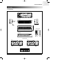
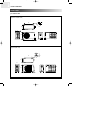
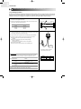
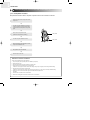
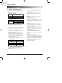
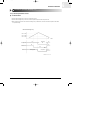
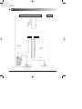
5-2-1. Fixing the Installing plate.
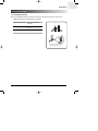
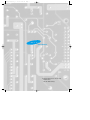
1. Determine the position of the pipe and drain hose
hole refering to the right figure and drill the hole with an inner diameter of 65mm
so that it slants slightly downwards.
Pipe hole
(Ø65mm)
2. If you are fixing the indoor unit to a… Then follow Steps…
3.
Window frame
4 to 6.
3. Fix the installation plate to the wall in a manner
appropriate to the weight of the indoor unit.
7K/9K
(Unit : mm)
60
Wall
30mm
Installation plate
252
275
19
If you are mounting the plate on a concrete wall with anchor bolts,
anchor bolts must not be projected by more than 20mm.
100
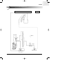
4. Determine the position of the wooden uprights to be attached to the window
frame.
158
12K
60
5. Attach the wooden upright to the window frame in a manner appropriate to the
weight of the indoor unit.
252
275
45
5
3/27/03 2:41 PM
6. Using tapped screws, attach the installation plate to the wooden upright,
as illustrated in the last figure opposite.
90
165
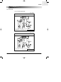
5-2-2. Purging the Unit
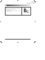
On delivery, the indoor unit is loaded with an inert gas. All this gas must therefore be purged before connecting the assembly
piping. To purge the inert gas, proceed as follows.
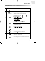
Unscrew the cap at the end of each pipe.
Result All inert gas escapes from the indoor unit.
◆ To prevent dirt or foreign objects from getting into the pipes during installation,
do NOT remove caps completely until you are ready to connect the piping.
28 | SAMSUNG