1
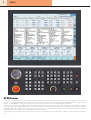
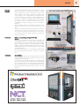
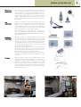
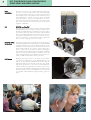
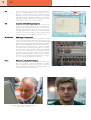
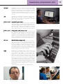
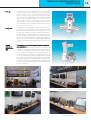
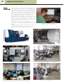
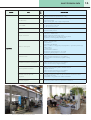
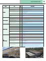
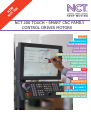
N NE
CT W
20
0
NCT 200 TOUCH - SMART CNC FAMILY
CONTROL DRIVES MOTORS
BASICS
HANDLING
PROGRAMMING
MORE CHANNELS
HIGH SPEED
MACHINING
PROBING IN MACHINE TOOL
NCT SYNCHRONOUS
ASYNCHRONOUS
SERVO DRIVES
SERVO MOTORS
PLC
COMMUNICATION
SOFTWARE UPDATE
SAFETY
DIAGNOSTICS
SERVICES FOR INCREASED
ACCURACY
OF MACHINE TOOLS
EXAMPLES FOR APPLICATION
BASIC TECHNICAL DATA
1
BASICS
NCT 200 Control series
The evolution of electronics, faster microprocessors, internet, high-speed networks, mobile world, the endless range of PC peripheries and services
turned the conservative industrial electronics upside down. These days a successful CNC is unthinkable without ETHERNET connection, high capacity
memory, or a PENDRIVE for saving part programs or without any cursor device (mouse, touchpad, trackball, touchscreen).
The CNC system software has to adapt to the usual management techniques of PC (select, copy, search, file management etc.) and file compatibility
is very important for the portability of programs. Windows Embedded, the operation system developed for industrial automation has been installed
in the NCT 200 controls to fulfill these requirements. The connection between the peripheries and the central unit managed by standard industrial
ETHERNET (EtherCAT) channel, which is a worldwide standard these days.
And something else! The default screen of NCT 200 control series is a touchscreen that is widely used in industrial computers (IPC) and mobile devices.
BASICS
NCT 201
hardware
The NCT 201 is the first member of NCT 200 series control
family. The industrial CNC CPU of the NCT 201 is located
behind a large LCD monitor and provide a single unit for
easy installation. This hardware includes the complete CNC
software together with integrated PLC. All peripheries that
control the machine tool connect to CNC by EtherCAT channel that is a worldwide standard these days. Installer of NCT
201 is free to select the compatible elements from different
manufacturers and connect them to NCT control due to the
standardized periphery management and the worldwide
standard.
These EtherCAT peripheries are the operator keyboard, handwheel, wide range of PLC in/output devices and servo
drives.
The use of an operator keyboard designed by the integrator,
or retaining the original operating panel of the machine in
case of a control retrofit is easy and inexpensive. The peripheries of NCT and those of other manufacturers can easily be
mixed and matched.
Touchscreen
Reliable, easy cleaning and operator-friendly
Reliable
Touchscreen is a preferred user interface for industrial computers (IPC) that work in very rough conditions, and became
the standard screen option for mobile devices (phones, tablet
PCs) in the last few years. Due to high demand the TOUCHPANEL manufacturers developed their products to such a high
quality that their lifecycle is longer than that of the high quality
industrial pushbuttons.
We only use the touchscreen of the leading manufacturer of
the world and the lifecycle of that is more than 10 million
clicks.
Touchscreen
Easy cleaning
Frequently asked questions are whether the touchscreen will
be damaged by wet, oil-covered hands and how can the
polluted screen be cleaned.
The touchscreen is protected by a special non-reflecting adhesive foil that resists mechanical effects, and can be cleaned
by one movement with a soft cloth unlike the raised surface
of conventional keyboards. The inexpensive adhesive foil can
be replaced easily and quickly even by the user in case of a
damage.
2
3
BASICS
Touchscreen
User-friendly
The user-friendly interface (HMI) is the most important advantage of a touchscreen.
Data input is done by a virtual keyboard “painted” on the
touchscreen. The keyboard picture only appears and takes
up screen space when data input is possible. Adapting other
languages is not a problem due to the virtual keyboard; user
can select the language of keyboard easily. The size and location of buttons provides convenient data input. When pushing buttons a clicking sound can be heard.
The user friendliness of a control interface depends on how
many buttons need to be pressed to achieve a certain function. Of course, the target is the minimum button clicking.
Touchscreen also helps here. There are several windows in
the screen of NCT control at the same time. The button zone
in the lower section shows the control options of active window. Pressing its surface can activate any window.
Should the user prefer a PC keyboard, there are 4 USB terminals, and any type of PC keyboard can be connected to
one of them. The wired or wireless PC keyboard can be
placed on a tray under the machine operator panel in a convenient, ergonomic position. The keyboard tray can be ordered as an option.
Sound signals
There is a connection for speakers in NCT 200 control family
emitting clicking sound by pressing the keyboard screen, or
if there are alarm signals. A voice adviser option will also be
offered in the near future.
Nanointerpolation
The internal data management of NCT 200 control series enables the nano resolution path generation. Speed computing,
and all path and speed compensations are in nano resolution. The EnDat 2.2 measuring system and EtherCAT communication channel assure the resolution and speed required by
nanointerpolation. It provides enhanced accuracy and surface finish during machining.
Mr. Antal Szabó, chief engineer of electricity
and PLC design
Mr. Zsolt Vadász, electrical engineer,
installing NCT 201 in a machining centre
Programming on myNCT
Mr. Róbert Goron, electrical engineer,
installing NCT 201 in a BUFFALO horizontal lathe
HANDLING, PROGRAMMING
Windows in
screen
Create your own user interface that offers the most convenient
operation!
The reason for application of window structure is user interface created in WINDOWS operation system. Each window
is an individual panel whether or not contains data input or
other control options. User can locate panels anywhere in the
screen in arbitrary disposition. Panels can be resized optionally. The screen composed by user can be saved or also
frozen. The frozen screen can not be modified (resize or close
panels).
Windows in
screen
Manual data input
The features of manual mode are important to manage the
user-friendly supply of CNC machine tools. The NCT 200
controls also excel in this subject. The control saves the issued
commands and lists them on the screen. By highlighting any
command line on the list, the commands can be issued
again.
Compatibility
Lathe, mill, grinder, sheet metal cutter CNC
It is a great advantage if different type of machine tools can
use the same control and the operating and programming
system is compatible among them, and there are only technological differences. The NCT 200 series controls can be
installed in different machine tools, and only specific PLC programs and necessary technological macros need to be developed.
Efficiency, Compatibility
ISO programming = Efficiency, Compatibility
The programming and executing of programs in the NCT
200 controls is fully compatible with previous NCT 100 control series and with several Japanese and American CNC
controls. This is the easiest solution to connect CAM systems
to NCT 200 series. This is an efficient, fast programming language, the worldwide alphabet of CNC techniques.
MACRO
MACRO programming by defining symbolic variables
The popular MACRO programming used in NCT 100 controls is also available in NCT 200 controls. The advantage
of the new Macro system is that the variables of the macro
program can also be referred to by symbols.
myNCT
myNCT
However, the most efficient CNC program is still written in
G-codes, the program writing time, not the program executing time has to be reduced at single piece or short-run production cases. The myNCT program editor helps in this
activity. The machining can be done and simulated graphically by drawing the contour of workpiece and filling some
dialogue charts in a few minutes. Of course you can do it
while executing another part program.
Mr. Pál Maklári, quality controller of NCT,
making the final inspection
Visitors of the Industria exhibition in Budapest
4
5
MORE CHANNELS, HIGH SPEED MACHINING
More channels
One of the most important advantages of the NCT 200 controls is the multi-channel structure. It means several logical
CNC controls in one physical unit. Each channel is an individual CNC control that executes its own technological program by continuous coordination with the other channels. The
number of channels limited by only the speed of CPU, that
can be at most 8 in the present system. The control has all
the features and functions which are necessary for multi-channel CNC machine tools, such as special tool management
or simultaneous, transposed or superposed axes.
HSHP
High-speed high precision machining path
You move much slower on a curvy unknown road than on
one, where someone always determines the speed to take
the next curve safely. The tool path generator of the CNC
reads ahead up to 1000 blocks before execution to ensure
maximum machining speed and computes the feed speed of
the next contour element by making sure not to exceed the
safe acceleration and deceleration parameters of the machine tool.
Point filter
The CAM programs often generate unnecessarily short movements by machining the respective contour. By switching on
the point filter option the machining speed will significantly
increase without decreasing the accuracy. In this case the
point filtering combines programmed movements into a block
as long as the amount of movements does not exceed the
limit of any axis defined in parameter. The block generated
by combined movements is a straight line between the starting point of first block and the endpoint of last block.
Acceleration
deceleration
The execution of acceleration/deceleration influences significantly the speed of high-speed high precision contouring
(HSHP). The NCT 200 controls change speed parabolic so
it provides the fastest path speed by the smallest load of mechanics of machine tool.
High speed and high precision Topper MC
from Tong Tai with NCT 201
NCT 201 in five-channel operation
Two-channel Swiss-type lathe controlled by NCT 201
BUFFALO LT-52 Slant-Bed Lathe with NCT 201
PROBING IN MACHINE TOOL
Measuring in
machine tool
Tool or workpiece touch probe from any manufacturer can
be connected to NCT 200 controls by ETP card. MES software integrated in control manages high variety of touching,
measuring functions, the DIGI program package touches control path and complex surfaces. Some manufacturers (RENISHAW, M&H) offer software packages for their touch
probes. These MACRO programs can also be installed in
NCT controls.
Tool
measurement
The tool is essential to ensure machining accuracy of the
workpiece. The tool geometry can be measured quickly and
safely by doing measurement in machine tool. Tool dimensional changes caused by tool wear can be managed by
programmed measurement cycles during machining and tool
wear or breakage of tool can also be inspected.
Tool measurement can be also performed on stationary or
driven tools. Mechanic or laser device of several manufacturers (HEIDENHAIN, RENISHAW, M&H) can also be installed to NCT controls.
Workpiece
measurement
Although workpiece touch probe is traditionally used for quick
and accurate probing of workpiece zero point, the demand
increases for measuring workpiece during machining. During
machining the geometry of workpiece could change significantly and the necessary accuracy could not be ensured without measurement during interruption of machining, because
of internal structural transformations.
Measurement cycles could be used for the most frequently
used measuring tasks (shaft, bore, corner point, etc.). Coordinate transformation after measurement provides the accurate machining for incorrectly clamped workpiece.
Measuring and calibrating rotating axes of 5 axis machine
tools have done quickly and easily by measurement in machine tool.
Digitizing
Digitizing inside of machine tool is actually a series of measurement. Software module integrated in control drives the
workpiece touch probe along the workpiece contour in range
defined by cycle parameters. In touching points the coordinates of touching sphere central point saved in technological
program specified by operator. In this method a contour received is parallel to the original, that is generated by using
CAD/CAM software.
Mr. Gergely Kasznár, mechanical designer, with a special purpose application of a Topper vertical lathe (for machining wheels for high
speed rails)
Mr. Péter Balogh, electrical engineer, installing NCT 201
in a Tong Tai Honor Seiki vertical lathe
6
NCT SYNCHRONOUS AND ASYNCHRONOUS
SERVO DRIVES AND SERVO MOTORS
7
NCT
servo drives
The NCT servo drives are complete EtherCAT peripheries.
They are connected to NCT 200 control central unit (EHU)
by one EtherCAT bus. Moving commands are received and
also absolute position transmitted to CNC software by using
this wide-frequency channel. NCT servo drives are developed especially for machine tool applications. The NCT
servo drives are the essential peripheries of the NCT controls
due to their extremely fast and accurate current and speed
regulation capabilities.
SoE
SERCOS over EtherCAT
The NCT control communicates with servo drives by a widely
used standard protocol. Using servo drives of several manufacturers is possible because of standard connection. Setting
servo drives is done from NCT control easily, without external
device. The tested parameters are saved in control. The control loads the parameters into each servo drive every time
when it is switched on, so the parameter setting is automatic
also in case of changing motor or servo drive.
Parameter setting
Servo drives
The NCT servo drives are connected to NCT control by using
standard SoE (SERCOS over EtherCAT) or CoE (CAN OPEN
over EtherCAT) protocol, so servo drive parameters can be
loaded from control. Parameter sets of servomotors and servo
drives saved in HDD of the control. In case of starting up a
system consisting of control and servo drives or changing a
servo drive the assigned parameters are loaded immediately
and the servo drives will be ready for operation. There are
ready, tested parameter sets for all NCT synchronous servomotors in HDD of NCT 200 controls for our users.
NCT motors
Developing NCT servomotors is one of the most successful,
most effective developments of our R&D department. The
NCT A, Ai, AiS, AMS and TORQUE motors also satisfy the
highest demands. The mechanical construction, size, speed,
and electric parameters of our motors are developed especially for machine tool applications. However, the Ai motors
are mounted with EnDat 2.2 absolute rotary encoders as standard, each NCT servomotor is available with incremental TTL
or sinusoidal output (SINCOS/1Vpp) measuring system as
option.
Mr. József Deák, sales director of NCT, in negotiation with customers
Mrs. Krisztina Tóth, sales manager of NCT
NCT SYNCHRONOUS AND ASYNCHRONOUS
SERVO DRIVES AND SERVO MOTORS
Synchronous
servo motors
NCT synchronous servo motors are available in 1 Nm -75
Nm torque range with three flange sizes. The shaft design
and connecting main dimensions are compatible with similar
sized motors of several Japanese manufacturers.
Asynchronous
spindle motors
High-speed asynchronous motors are primarily used for driving spindles of machine tools, and are available with throughbored shaft and up to 15000-rpm speed. Air- or liquid
cooling is also available depending on size and construction.
Torque motors
The TORQUE motors can rotate or tilt a rotary table or milling
head directly, without inserting any drive mechanism. These
motors can produce extremely high torques constantly because of high intensity liquid cooling.
BUILT-IN
SPINDLES
MOTORS
- Higher dynamics because of smaller inertial mass, lower
loss, lower current drain
- Better workpiece geometry thanks to the lack of deformation
caused by belt tension
- Higher lifetime, better surface geometry on workpiece and
higher tool insert life thanks to much lower vibration level
- Better workpiece geometrical and repeating accuracy,
longer lifetime of bearing thanks to lower thermal deformation because of high intensity liquid cooling
- Long bearing lifetime
- Low noise level
These are the advantages of lathe built-in spindles compared
to conventional belt drive. The liquid-cooled lathe built-in
motor spindles are available in two center line sizes and several spindle dimensions.
Mr. István Kiss , sales manager of NCT, meeting clients
Mr. István Póka, (CEO) introducing the new NCT 201
to a customer
Mr. Árpád Nyitrai, sales engineer of NCT, meeting clients
Mr. Szilárd Kerekes, director of NCT Sales Office in Romania
8
9
PLC
PLC
The PLC integrated in the NCT 200 controls can be programmed in popular LADDER system, providing effective error
detection for maintenance and repairing personnel. Ladder
displayed in the PLC window and the “green flow” represents
logical states and processes during operation. High-level language (PYTHON) is available for PLC programmers, machine
tool builders to create their own user interface.
EPU
Locomotive of EtherCAT IO periphery train
Coupler unit (EPU) with EtherCAT connection create an IO
periphery with periphery elements connected by LVDS bus.
These units can be placed at any point in the machine. The
full length of EtherCAT network can be up to several kilometers. The maximum distance between two network elements
can even reach 100 meters. A lot of wiring could be saved
in IO peripheries located optimally inside the machine.
IO peripheries
Wide range of IO peripheries
The peripheries of NCT controls are connected to the CNC
control central unit (EHU) by EtherCAT channel. They can be
NCT IO units, NCT servo drives, and also standard EtherCAT
peripheries from other manufacturers (BECKHOFF, YASKAVA,
ABB, HITACHI, BAUMÜLLER, LENZE, SEW, WAGO etc.).
The IO periphery system developed to connect “carriages”
with different tasks, in different length to EPU (“Locomotive”)
with EtherCAT connection by ribbon cable, using LVDS bus.
This “train” “runs” on DIN rails which are widely used in building electric panels and cabinets. There are 20 “carriages”
(periphery modules) available for different tasks currently, but
the selection is constantly extended and arbitrary “carriages”
can be constructed for different user demands.
Phyton
Programming using high-level language
Graphical user interface customized to a task make it easier
and more convenient to operate a barfeeder connected to
lathe or a palette changer of a machining centre. High-level
language (PYTHON) is available for PLC programmers, machine tool builders to solve these tasks.
Mr. Zoltán Gábor, director of MICROMATIC Ltd.,
partner company of NCT
Mr. Attila Csapó, director of FÉMO Ltd, NCT's partner company
COMMUNICATION, SOFTWARE UPDATE, SAFETY
ETHERNET
ETHERNET connection is a basic accessory of each part of
NCT 200 control series. It can be connected into any WINDOWS network (TCP/IP protocol, 100 Mbit/sec speed)
without any external software. After that a part program can
be loaded easily into the HDD of the control, or it can be assigned to run and execute without loading it into the memory
of control.
USB
There are 4 pcs of USB ports on the NCT control to receive
USB peripheries as usual in world of PC. PENDRIVE, keyboard, various cursor units (mouse, TRACKBALL, TOUCHPAD
etc.) can be connected here.
Software update
I.
Update NCT system software
The system software of a NCT control will be constantly developed, expanded in the following years. New versions with
improved knowledge; functions will be expected to be introduced every 2-4 months. An important feature of the NCT
200 control series is that users can install the new software
version easily, and it does not require the assistance of NCT..
Software update
II.
Change system software of servo drives
NCT is constantly developing its products and install new features continually. These changes could improve an existing
knowledge or install a completely new one. System software
of CNC or even servo drive can be reinstalled by machine
builder or user conveniently without requiring the assistance
of NCT. The features of new software versions are in the NCT
website and the software can be downloaded from here.
ESIC card
(EtherCAT Software Integrity Card)
This unit is a multi-function part of the NCT control hardware.
The operational job is to manage EtherCAT junction, write
dynamic non-volatile memory and manage software protection key and PAYBIT. The software protection saves the list of
options purchased by the user and it enables or disables
using of them based on the list. In case of replacing the control, all purchased functions will be transferred to the new control by inserting the card into the new control.
Paybit
PAYBIT function is available for NCT controls. This is an option for selling party to switch off the control in case of payment contention. The PAYBIT is a remote function. The
operating time is determined by the machine builder and is
saved in the memory of ESIC card of control. Any working
time can be set in hour resolution. After the setting time expired the control decreases the upper limit of speed range
shift (OVERRIDE) and decreases rapid traverse and feeding
speed for 8 hours by 20%. Decreasing speed is a warning
for user that the machine will stops in a few work tours. Manufacturer could switch off or set delay for PAYBIT by phone or
remote computer function. PAYBIT function is an option for us
if necessary.
Customer has to be informed about the PAYBIT function!
Mr. Robert Pilcz, director of SLOVTOS Ltd.( Slovak R.),
NCT’s partner company
Offline programming, program transfer on ETHERNET channel
NCT control in operation
Customers at the INDUSTRIA exhibition in Budapest
10
11
DIAGNOSTICS
Logbook
Creating Logs, sending log file
The inspection module of NCT inspects and records every
event and creates an event history!
The NCT 200 controls save each important event in a log
file. In case of any malfunction during the operation of the
unit, whether or not it was caused by error of servo system,
operator error, or error detected by PLC. This log file can
be sent to the NCT customer service center by email. Control will be an open book for NCT professionals by log life.
There is a tutorial video in Youtube to manage log files for
users (create an NCT 201 error log file).
Remote machine
Remote diagnostics can be performed by means of the “remote machine service”. If the customer can provide a login
facility to the NCT control the NCT technicians can connect
to the user interface and manipulate the CNC control from a
remote PC, no matter where the machine is located.
Auto parameter
setting
The NCT asynchronous servo drives are often connected to
motors without known, tested parameter set. The “auto parameter setting” function integrated in our asynchronous servo
drives is used to install these motors. The user only has to enter
into the CNC control the original parameters found on the
motor data plate. The servo drive software analyses and computes an optimal parameter set to achieve the best motor control. Of course the computed parameters will be refined,
saved and reloaded after adjustments.
Services to
help setting
servo axes
Diagnostic functions help error detection and tuning of servo
axes. The characteristics of commands issued by the path
generator, speed, position, tracking error (lag) of axes can
be displayed in the oscilloscope screen integrated in to the
control. By using circular test you can verify whether the settings and the operation of servo system are correct, without
using external unit. Of course the features can be displayed
in numeric format and in a chart.
NCT booth on the Industria exhibition in Budapest
Mr. László Horváth Director of R&D department consulting
with customer at Industria exhibition
DIAGNOSTICS
Oscilloscope
Oscilloscope with digital memory integrated in the control is
essential for accurate setting of servo drives. The signals displayed graphically in relation to time can be set in 4 channels
simultaneously. These can be signals of servo system, PLC IO
lines or state of internal flag bits or value of variables. Saving
starts when START button pressed is independent from fulfilling
triggering conditions. Measurement continues until available
memory for saving data is full if triggering conditions (channel, positive/negative transition) fulfilled. If data fills more than
a half of memory before fulfilling triggering condition than
saving continues until triggering point will be placed in the
middle of memory.
These settings can be saved and loaded. The inspecting part
can be searched, the selected interval could be increased,
decreased, the size of signal could be increased, decreased,
the signal could be offset vertically. The measuring results can
be saved in .xls file format to transfer them to an external computer for additional analysis.
Logic analyzer
The PLC connection signals and their condition can be selected by name and can be displayed in 18 analyzer channels, and they can be studied in relation to time on the control
screen. Any channel could be assigned as triggering source
either by falling or rising edge. Elapsed time from triggering
point or distance between any two moments can be measured. Measurement results can be saved in a selected file, or
measurement can be started immediately by loading any
saved configuration.
IO test
The IO lines which can be either “read/write”, or “read only”
by the PLC will be displayed in a clear table.. Some of these
are physical input and output signals between machine tool
and CNC, while others are the communication lines between
PLC and CNC. Bit setting (SET/RESET) or overwriting memory range is possible..
Symbolic IO
PLC variables can be displayed below each other in any convenient order. Name, address and contents of variables can
be displayed in binary or decimal representation..
TestMes measuring system test
The servo settings will always be performed by inserting the
expected parameter values in the displayed table. The required properties of the table can be selected by the softkeys
below.. The servo axes are displayed in the rows of the table,
while their properties are displayed in the columns of the
table.
Mr. István Végh, giving technical advice to customer by phone
Mr. Tamás Pintér, chief engineer of technology of NCT, programming
a two-channel Swiss- type lathe
12
13
SERVICES FOR INCREASED ACCURACY OF
MACHINE TOOLS
Reversal error
This is the basic compensation for each machine tool control.
Most of the time the movment of a slide is generated by the
rotation of a servomotor. When reversing direction, the motor
rotates for a short interval as the slide does not move yet, because of the backlash and flexibility of mechanical parts that
transform rotational motion into straight-line or rotational motion. This movement lag can be corrected by the value in the
“Backlash” parameter that compensates also linear and rotating axes.
Linear accuracy
The most commonly used and most appropriate measuring
device is the laser interferometer that measures the effective
position of axes between movements by 0,1 micron resolution. The measuring results can be saved in the Pitch Error
Compensation parameters of the CNC control and the measured position can be modified in each point based on these
data. The reversal error compensation will be performed automatically if the laser measurement is done in both directions
of an axis.
Reversal
acceleration
This compensation reduces significantly the oscillation of
servo axis and the dynamics of a machine tool equipped with
linear scale can be increased, even in case of very “loose”
mechanics. While machining with low feed or in circular interpolation the speed of the servomotor will be the highest
when the slide starts to move due to backlash. Usually there
will be a state of oscillation that is difficult to manage. The
reversal acceleration will speed up the servo motor and after
a preset time or distance the normal speed signal will be restored. This needs to be set the way, that when the slide starts
to move the servo drive has already been programmed for
the normal feed command.
NCT 201 on a Tong Tai Topper TNL-130AL machine
JINN FA-NCT gang-type lathe with supporter and barfeeder
VD-510S new tapping centre with NCT 201
New BUFFALO LT-52 slant-bed lathe with NCT 201
SERVICES FOR INCREASED ACCURACY OF
MACHINE TOOLS
Stick slip
The phenomenon of stick slip can occur on wide flat box
ways where the stick slip compensation can be used effectively. The slide movement can be initiated by a “kick start”
through a parameter with preset time and speed impulse
value, and by immediately returning the speed to the normal
value as soon as the slide started to move. This eliminates
excess speed caused by increasing speed command generated by position control loop for stick slip. The position control
loop oscillated by excess speed significantly decreases the
dynamics of the servo circuit.
Straightness
The straightness of moving slides is essential for machine tools
as well as for the positioning accuracy. However, builders
tend to develop the best geometry and straightness for their
machine tools, improving machining or fitting accuracy above
a certain value is not practical. Electronic compensation can
be used efficiently in these cases. The straightness deviation
of axes has to be measured before adjusting the relevant parameter. The control manages to move axes perpendicular to
movement by setting the value after filling in measurement results.
Thermal
deformation
compensation
TDC
Compensation of thermal deformation based on temperature measurement
Direct position measurement by linear scale is a perfect solution that compensates thermal deformation of linear axes of
a machine tool. Although deformation of elements that can
not be or difficultly measured directly is a significant problem,
for example at the headstock of C column type milling machines. The headstock is heated by spindle bearings, spindle
motor, and cooled by coolant and the active cooling of spindle motor and spindle. Thermal deformation of headstock can
be compensated by self-adjusting software model integrated
in NCT control, based on signals of thermal measurement
sensors in headstock.
NCT booth at the EMO exhibition in Hannover Germany
NCT 201 controls at the EMO exhibition
NCT asynchronous drives and motors exhibited at the EMO
NCT synchronous servomotors and built-in spindle motor
exhibited at the EMO
14
15
EXAMPLES FOR APPLICATION
NCT 201
on machine tools
Offering professional and also efficient CNC package for
machine tool manufacturers and machine rebuild personnel
has always been an important aspect in development of NCT
CNC controls. NCT 200 series are the most developed
products also in this aspect. It can be connected to almost all
type of machine tools from a single spindle lathe to the most
complex multi-channel multi-axis machining centers even in
turning, milling, grinding, cutting or manipulation functions.
Although we assume the rebuilding and retrofitting of CNC
machines with new electrical design, documentation, PLC
programming and turnkey completion, we are mostly committed to find partners worldwide who can solve this really
complex task by on their own, with our help.
Our machine tool builder or retrofitter partners receive ready
PLCs and the machine parameters developed by us free of
charge.
Well-skilled professionals of our technical online team can
help solving problems installing, operating controls by phone,
internet, email or also personally if it is needed.
Mr. Ferenc Deák, software developer,
supplying a client in India via SKYPE
TOPPER TNL-130AL Tong Tai machine controlled by NCT 201
Big BUFFALO horizontal lathe with NCT 201
VD-510S tapping centre with NCT 201 control
JINN FA-NCT gang-type lathes on the assembly line
NCT Academy CNC education Ltd., for the skilled clients and partners in
the field of technologic programming and operating and PLC programming
School room for practical education
ITEM
S/O
BASIC TECHNICAL DATA
1,8 GHz ATOM CPU
S
High speed by minimal heat production
Control panel does not require external cooling
16 GB memory
S
Running CAD/CAM files do not require external computer
Semiconductor HDD
Without moving parts, only a single Compact Flash
4 pcs of USB
S
100% PC compatibility
Any PC keyboard can be used
Any PC screen can be used
Ethernet
S
Connect to office computer network
Standard TCP/IP protocol
S
19” or 15” size
Touchscreen – default screen
Default programming keyboard in screen
Lifetime of touchscreen is 10 million presses (anywhere)
Long lifetime, interchangeable protecting foil
S
ALPS pushbuttons
Lifetime is 10 million clicks
IP 54 protection
Each button have LED light
Modes, conditions, moving (JOG), start/stop buttons, speed and spindle range
shifting switches
1 pc key switch
Place for built-in handwheel
20 buttons for general purpose in 19” model
8 buttons for general purpose in 15” model
Feedrate override
S
Magnetic arrestment
Without mechanical arresting unit – long lifetime
Absolute position measurement by magnetic indexing
31 ranges
Handwheel mounted in control panel
O
Magnetic arrestment
Without mechanical arresting unit – long lifetime
Rotation measurement by magnetic indexing
External, portable handwheel
O
Separated handwheel possible per axes
Modes, moving and starting buttons, feedrate override
Magnetic arrestment
Without mechanical arresting unit – long lifetime
Rotation measurement by magnetic indexing
EtherCAT communication with
peripheries
S
IO peripheries and servo drives can be connected to one Ethernet network
Easy, inexpensive wiring
Compatibility – using products of another manufacturer
EtherCAT peripheries
O
Wide rage of variety
Manufacture specific solutions by respected user demands
GROUP
Graphic touchscreen
Machine control panel
HARDWARE
NCT’s shop floor of CNC machine production
DESCRIPTION
Electronic production
16
17
ITEM
S/O
BASIC TECHNICAL DATA
Windows Embedded operation system
S
Windows file management
Using standard WINDOWS peripheries
Open Windows professional platform
O
NCT 202
Any application can be run beside of NCT HMI (user interface)
CAD/CAM application (VECTOR, EdgeCAM)
S
ESIC - electronic protection card (EtherCAT Software Integrity Card)
Protecting options
Dynamic memory management without data loss
PAYBIT
EtherCAT junction (external handwheel)
Softwares downloaded from Internet
S
CNC system program
Servo drive system program
Servo parameters
Ready, tested PLC programs for different machine tools
Application shop (NCT 202)
Work piece time calculation
S
Work piece time calculation (real time)
Take into account tool change time and other secondary times
Also works in test run
Graphic display
S
125 us speed control
1 ms path compute
1 ms record processing
1 ms position control
10 ms PLC base
1 ms PLC quick module
Axis max. number
O
Max. 8 channel
Max. 32 axes
Max. 16 axes per channels
Max. 16 spindles
Selectable main spindle for cutting, thread cutting, tapping per channels
Standard axis number
S
Lathe: 2 axes + 1 spindle
Milling machine: 3 axes + 1 spindle or 4 axes
PLC axes
O
Moving axes from PLC program
PLC axes number
O
Not limited, any axis can be defined as PLC axis
Reference signal output
S
EtherCAT
Reference signal output IO train
O
Analogue
CAN BUS
Pulse forward/backward
Pulse + direction
Generate TACHO signal
O
Issue proportional analogue tacho signal to measuring system signal frequency in
motor shaft
Issue command signal in one analogue line (reference signal - speed)
Position feedback by servo drive
O
EtherCAT
TTL
1 Vpp (voltage sinusoidal)
11 uApp (current sinusoidal)
Position feedback by IO train
O
EnDat 2.2 (HEIDENHAIN linear scale)
TTL (retrofit)
1 Vpp (voltage sinusoidal)
11 uApp (current sinusoidal)
Taking reference point by NCT
servo drive
S
Absolute EnDat 2.2
O
Absolute EnDat 2.2
C type (HEIDENHAIN linear scale, angle gauge)
Reference pulse
Switch
S
Backlash error
Thread pitch error
Backlash acceleration
Stick slip
Straightness
GROUP
Intelligent software protection
BASIC CNC
Cycle intervals
AXES
Taking reference point by IO train
Compensations
DESCRIPTION
GROUP
SPINDLES
MORE CHANNELS
INTERPOLATION
FEED
RAPID TRAVERSE
ITEM
S/O
BASIC TECHNICAL DATA
DESCRIPTION
Spindle max. number
O
Max. 16 spindles
Max. 16 spindles per channel
Simultaneous running
O
Several spindles running simultaneously
Electronic interlock between spindles
O
Electronic interlock between spindles
Ratio set by parameter
Gear cutting functions
Polygon turning
Rigid tapping
O
Different acceleration for drilling and retracting set by parameter
Orienting
S
To zero pulse of encoder
To switch
Number of channels
O
Max. 8
Represent channels
O
User can create its own screen
Relation between channels
O
Wait from technological program
PLC
Special axis management
O
Synchronous control
Superimposed control
Mixed control
Linear
S
Positioning
Feed
Circular
S
Along several quadrants
Variable radius circle
S
Spiral of Archimedes
Complex
S
Circular along 2 axes + linear along max. 14 axes
Special
S
Polar coordinate
Cylinder
Tapping
S
Uniform pitch
Through several records
Different pitch
Finishing (SMOOTH)
S
Laying third degree Bezier spindle curve
Feed
S
Per minute
Per revolution
Feedrate override
S
Operated from PLC
Acceleration/deceleration
S
Linear
Quadratic
S
Continuous cutting mode
Exact stop mode
Corner override mode
Tapping mode
S
Internal machining of circle in G41, G42 state in the ratio of programmed and
corrected radius
Machining of circle in function of circle radius and permitted acceleration/
deceleration
Machining corners, in function of speed deviation set by parameter
Feed control functions
Feed automatic decrease
Head office building in Budapest Hungary
Buildings of the NCT's machine tool production
18
19
GROUP
HSHP
High speed and
high precision tracking
COORDINATE
SYSTEMS AND
TRANSFORMATIONS
ITEM
S/O
BASIC TECHNICAL DATA
Nanointerpolation
S
Path computing, compensations in nanometer resolution
Increased surface quality
Acceleration/deceleration
S
Quadratic speed change
Acceleration/deceleration without knocking
Multibuffer mode
S
Read forward 1000 blocks
Switch on
Switch off
Feed forward
S
Tracking by decreased lag
Point eliminator
S
Smoothing path generated by external device
SMOOTH
S
Smoothing interpolation
Bezier spline
Number of workpiece coordinate
systems
S
6 + 99
Transformations
S
Rotating
Mirroring
Scaling
Select plane
S
X-Y
X-Z
Y-Z
PLC integrated in CNC
S
Quick, economic
Max. number of IO lines
O
512 INPUT
512 OUTPUT
IO modules
O
16, 32 line inputs
16 line semiconductor outputs
8 line relay output
Analogue input/output units (+/-10V, 4-20 mA)
Linear scale connection
Touch probe connection
Pulse issue forward/backward
Pulse issue (A, AN, B, BN)
Pulse issue pulse/direction
Ladder programming
S
Well-known programming language appropriate for international requirements
Easy error detection
Ladder display
S
Real time display of PLC processes in CNC
Green flow
Testing PLC
S
Logic analyzer
Current flow display
Remote diagnostics
S
Connect to remote computer
Logbook
S
The inspection module of software inspects and saves everything
Graphic display
Temperature diagnostics
O
Increased accuracy by compensating head deformations
Measuring temperature in 8 points
Vibration diagnostics
O
Increased safety
Machine inspection
PLC
MACHINE
INSPECTION
DESCRIPTION
Retrofitting a Mori Seiki lathe with NCT control (USA)
NCT partner in the USA
GROUP
SOFTWARES TO HELP
TECHNOLOGICAL
PROGRAMMING
FUNCTIONS TO HELP
TECHNOLOGICAL
PROGRAMMING
MANAGE PROGRAM
EXECUTE PROGRAM
SERVO DRIVE
TECHNICS
S/O
BASIC TECHNICAL DATA
ITEM
DESCRIPTION
myNCT
O
Easy, effective programming
Most effective solution for programming in machine tool
ASSIST
S
Interactive screen for help programming
Interactive screen for help operating
Running CAD/CAM program in CNC
O
NCT 202
Windows 7 platform
VECTOR, EdgeCAM
Cycles
S
Drilling cycles
Simple turning cycles
Complex cycles (turning roughing, facing roughing, grooving, thread cutting, etc.)
User specified cycles
O
Cycles written in MACRO programming language
Define chamfer
S
,C
Define fillet
S
,R
Intersection point computing
S
Line – line
Line – circle
Circle - line
Circle - circle
Subroutine technique
S
4 calling levels
Conditional block skip
S
Max. 9 switches
Macro programming
S
Effective solution for programming user cycles
AUTOMATIC
S
Assign selected program file to run
MDI
S
Execute new program when interrupt AUTOMATIC execution
Handwheel
S
Program execution controlled by handwheel
EnDat 2.2 rotary encoder
S
Standard measuring system of Ai series NCT servomotors
33 million position/revolution
Absolute measuring system through 4096 revolutions
EnDat 2.2 linear scale
O
Absolute measurement
50 nanometer resolution
SoE protocol
S
Sercos over EtherCAT
CoE protocol
S
Can Open over EtherCAT
Servo drive parameter setting
S
From CNC without using external unit
Loading ready, tested parameters from directory
Generate servo drive parameters of asynchronous servomotors using
original parameters of motor (data table)
Refreshing system program
S
From CNC without using external unit
Servo drive setting
S
Autotuning
Oscilloscope
Circular test
Tandem mode
O
Tandem mode of synchronous servo drives
Tandem mode of asynchronous servo drives
Power supply
O
Recuperation careful with mains
O
By standard protocol (SoE, CoE)
Analogue +/-10 V
Pulse issue forward/backward
Pulse issue (A, AN, B, BN)
Pulse issue pulse/direction
Connection to other servo drives
Mr. George Dabis, director and Mr. Steve Matis chief
engineer of Marathon Ltd. in HOUSTON (USA)
Special purpose lathe for machining seals
with NCT control (USA)
Mr. László Fekete, chief software developer of NCT, giving
technical support to Marathon Ltd. in Houston (USA)
20
BASIC TECHNICAL DATA
GROUP
ITEM
S/O
21
A series
O
Ferrite magnet
Ai series
O
Neodymium magnet
AiS asynchronous motors
O
Liquid cooling
Bearing cooling
Temperature measurement in several points
10000, 12000, 15000 speed
AMS power spindles
O
Liquid cooling
A2-5, A2-6, A2-8 spindle nose
Temperature measurement in several points
TORQUE motors
O
High intensity liquid cooling
Tilting milling head
Rotary table, indexing table
Oscilloscope
S
Display characteristics of servo drive features
Logic analyzer
S
Display PLC outputs/inputs in time diagram
Circular test
S
Graphic display of synchronous running servo drive axes
Check dynamics of servo drives
Does not require external unit
Display mechanical errors in machine equipped with linear scale
Simbolic IO
S
Dispay PLC variables in optional order
IO test
S
Display PLC outputs/inputs in chart
Measuring system test
S
Display servo drive features in chart
Recuperation braking
S
In case of recuperation, if capacitor has filled than energy flows into mains from
motor in generator running. Since machine tools have connected in common mains
with another consumers, they receive the generated energy so electricity meter rotates slower.
High capacity capacitor
S
Motor will be in generator running in braking, so energy flows to the servo drive, at
first, it fills the capacitor
Electronic gearbox
O
The electronic gearbox is cheaper than the mechanical construction and it has
lower current drain than a high power motor without gearbox. The users are always short of power and improving mains is very expensive. Furthermore it requires
smaller transistors, less capacitors, so the electronics is also cheaper.
Drain heat out from electric cabinet
produced by servo drives
S
Servo drives produce the most heat inside the electric cabinet. If this heat is drained
out from electric cabinet so it does not stoke the electric cabinet than it does not require energy for cooling electronics.
Switch off fans
O
Measure temperature of electric cabinet and cooling ribs and stop fans if possible
No undercooling
Decreased motor inertia
S
Less inertia = lower power requirement= lower loss
Modern power switches
S
Minimal loss
Minimal heat production
Thin grease lubrication
O
Does not pollute coolant water
Does not pollute environment
SERVOMOTORS
DIAGNOSTICS
ENVIRONMENTAL
AWARENESS
DESCRIPTION
Mr. Krisztián Lisztes, manager of NCT machine
production
Ms. Edit Szakálas, sales manager of NCT
(international sales)
Mr. István Póka CEO
GROUP
INTERPRETED
G-CODES
MACRO
PROGRAMMING
S/O
BASIC TECHNICAL DATA
ITEM
DESCRIPTION
Data determination
S
G20/G21,
G90
Incremental programming
S
G91
Also with operator I
Workspace limitation on/off
S
G22/G23
Interpolations
S
G0, G1, G2, G3
G12.1/G13.1
G7.1[axis address]r/G7.1[axis address]0
G33, G34
G5.1 Q2
G28, G30, G31 Qn, G37, G36
G84.2, G84.3
G50.2/G51.2
G4
Spindle oscillation inspection off/on
S
G25/G26
Feeds and its control functions
S
G94, G95, G96, G97
G9, G61, G62, G63, G64
Control functions of high speed
machining
S
G5.1 (P0, P1, Q1, Q0, R1, R2, R3)
Workpiece coordinate systems
S
G54, G55, G56, G58, G59, G54.1 P1-99
Coordinate systems, transformations
S
G52, G53, G92
G17, G18, G19, G50, G50.1, G51, G51.1, G68, G69
Tool corrections
S
G36, G37, G40, G41, G42, G43, G44, G49
Drilling cycles
S
G73, G74, G76, G80, G81, G82, G83, G84,
G84.2, G84.3, G85, G86, G87, G88, G89, G98, G99
Turning cycles
S
G70, G71, G72, G73, G74, G75, G76, G77, G78, G79
Macro calling
S
G65, G66, G66.1, G67
Variables
S
Symbolic
Local until 4 levels: #1-#33
Common: #100-#499, #500-#999
Definition
S
#i=<formula>
Arithmetical
S
Logical
S
NOT, OR, XOR, AND
Other
S
ABS, BCD, FIX, FUP
Functions
S
SQRT, SIN, COS, TAN, ASIN, ACOS, ATAN, EXP, LN
Conditional expressions
S
EQ, NE, GT, LT, GE, LE
Junction
S
GOTO(block number)
IF[<conditional expression>] GOTO(block number)
Cycle management
Data issue
Mr. László Horváth,
director of R&D department
+, -, *, /, MOD
WHILE[<conditional expression>] DOm…ENDm
S
POPEN, PCLOS, DPRNT, BPRNT, FOPON, FCLOS
Mr. Attila Apostol COO
Mr. József Deák, sales director
22
DISTRIBUTORS
SZENTPÉTERY PAVEL
Czech Republic
Praha 14000 Pod Vilami 3.
T: +420 234 123 341
F: +420 234 123 341
[email protected]
HUNOR DOO
Croatia
Zagrab 10000 Lipanjska 4.
T : +385 1 387 83 51
F : +385 1 387 30 07
[email protected]
BEAR Werkzeugmaschinen GmbH
Germany
Berlin, Kirchhofstraße 31. 13585
T: +49 306 170 2704
F: +49 306 170 2705
[email protected]
HUNOR-Naprawy OSN
Poland
35-328 Rzeszów
Popiełuszki ul. 22/63
T: +48 17 8541660
F: +48 17 8572216
mobil: +48 602 183692
[email protected]
www.hunor.pl
CNC AUTOMATIKA
Latvia
Ganibu Dambis 26, LV1005 Riga
T : +371 29207082
[email protected]
www.cnc.lv
ELEKTRONIS
Poland
65-077 Zielona Góra
Al. Wojska Polsklego 74/4
T: +48 68 411 13 99
F: +48 68 422 70 14
[email protected]
www.elektronis.pl
SLOVTOS spol.sr.o
Slovakia
Jasová 94134,
Pri Novych Zámkoch
T: +421 35 6477 110
F: +421 35 6477 103
[email protected]
KEREKES&Co Srl
Romania
Str.Teilor Nr.12/16
Cluj Napoca, Floresti Jud Cluj
T : +40 723 557 376
F:+40 264 279 732
[email protected]
[email protected]
Simultan Arad S.R.L.
Romania
Bucaresti
Str. Piscul Crasani NR.10 Sector 6.
T : +40 722 668035
F : +40 21 434 3861
[email protected]
JSC "STANKOTECH"
Russia
Moscow 127055
Novoslobodskaya str. 58
T : +7 499 97848 55
F : +7 495 643 61 67
[email protected]
www.stanko-nct.ru
MALEKS
Ucraine
Odessa, 65031
Promyshlennaya str. 37/4.
Odessa, 65005, box 98
T :+38 048 738-0735
T :+38 048 738-0736
F : +38 048 738-0735
F : +38 048 728-3098
[email protected]
www.maleks.odessa.ua
Marathon Machine Tools
USA
5515B-FM 1960 RD. East
Humble, TX. 77346
T: +1- 281-812-2324
F:+ 1-281-812-4160
[email protected]
www. marathon-excel.com
N C T I PA R I E L E K T R O N I K A I L t d .
H-1148 Budapest, Fogarasi street 7. * Tel.: (+36-1) 46-76-300 * Fax: (+36-1) 46-76-309
[email protected] * www.nct.hu