1
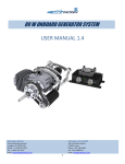
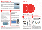
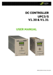
80 W ONBOARD GENERATOR SYSTEM USER MANUAL 1.3 UAV Factory USA LLC. 50 South Buckhout Street, Irvington, NY 10533 USA Phone: +1 (914) 591 3070 Fax: +1 (914) 591 3715 Email: [email protected] UAV Factory LTD. EUROPE 24A-52 Ganibu Dambis, LV1005, Latvia Phone: +371 29119398 Fax: +371 63048747 Email: [email protected] 1 1. Description Onboard Generator system consists of a Generator Power Unit (GPU), belt driven industrial-grade coreless generator, mounts and wiring necessary for installation on 3W 28i pusher engine. System was specifically developed to be used with UAV Factory's Penguin B UAV, but can also be used in other applications. GPU is designed to provide onboard dual voltage regulated power supply of 6 and 12 Volts. Despite small size, GPU offers outstanding efficiency as well as unique features such as the ability to monitor load, battery current, engine rpm, generator and battery voltage through serial communication. All power distribution parameters can be transmitted to the UAV ground control station and monitored during the flight. Integrated Lithium Polymer charger is used for the backup battery, which is switched on during the pre-flight checks, low engine speed or in the event of the engine failure. GPU is packed in a sealed aluminum enclosure and fitted with the high-end industrial push-pull connectors. Please refer to Figure 1 for a view of installed onboard generator system. Figure 1 80W onboard generator system installed in Penguin B UAV UAV Factory USA LLC. 50 South Buckhout Street, Irvington, NY 10533 USA Phone: +1 (914) 591 3070 Fax: +1 (914) 591 3715 Email: [email protected] UAV Factory LTD. EUROPE 24A-52 Ganibu Dambis, LV1005, Latvia Phone: +371 29119398 Fax: +371 63048747 Email: [email protected] 2 2. Key Features Light weight, small and efficient Up to 80 W continuous load power1 6 V and 12 V output Peak load current up to 10 A Short circuit protection Battery backup connection 3 cell Li-Poly integrated charger External power connection Integrated current sensors Serial connection IP 64 housing, IP 68 on request UAV Factory USA LLC. 50 South Buckhout Street, Irvington, NY 10533 USA Phone: +1 (914) 591 3070 Fax: +1 (914) 591 3715 Email: [email protected] UAV Factory LTD. EUROPE 24A-52 Ganibu Dambis, LV1005, Latvia Phone: +371 29119398 Fax: +371 63048747 Email: [email protected] 3 3. Specifications Electrical Specifications Generator voltage range External power supply voltage range Battery Type Battery Voltage Maximum battery charging current Maximum continuous generator current Maximum continuous battery current Maximum continuous external power current Output voltage Output voltage accuracy Maximum output voltage ripple 1,2 Continuous load current, 6 Volt output 1,2 Continuous load current, 12 Volt output Maximum GPU efficiency Maximum complete system efficiency Maximum peak load current No load GPU current Tachometer range Tachometer accuracy Current sensor range Current sensor accuracy Voltage sensor accuracy Serial Communication 13 – 35 V 13 – 50 V 3 cells, Lithium Polymer 12.6 V 2A 3.5 A 8A 8A 6 V and 12 V 0.2 V 50 mV@6V 50 mV@12V 5A 5A 90 % 75 % 10 A for 10 seconds 110 mA 1000-9000 rpm 200 rpm 0 to 10 A 0.2 A 0.1 V 5V TTL Mechanical Specifications Engine speed GPU Dimensions GPU Weight Complete Onboard Generator System weight Maximum GPU enclosure temperature Environmental protection Operating temperature Electrical connectors 1 1500 – 8500 RPM 59.4 x 115.8 x 32.4 mm ~190 grams ~500 grams 70°C IP 64 standard, IP 68 on request - 40°C to +50°C ² Fischer 104 Series push-pull connector Generator continuous current must not exceed 3.5 A ² Enclosure temperature must not exceed 70 °C , additional cooling may be required UAV Factory USA LLC. 50 South Buckhout Street, Irvington, NY 10533 USA Phone: +1 (914) 591 3070 Fax: +1 (914) 591 3715 Email: [email protected] UAV Factory LTD. EUROPE 24A-52 Ganibu Dambis, LV1005, Latvia Phone: +371 29119398 Fax: +371 63048747 Email: [email protected] 4 Figure 2 GPU dimensions in millimeters Figure 3 General view of generator assembly UAV Factory USA LLC. 50 South Buckhout Street, Irvington, NY 10533 USA Phone: +1 (914) 591 3070 Fax: +1 (914) 591 3715 Email: [email protected] UAV Factory LTD. EUROPE 24A-52 Ganibu Dambis, LV1005, Latvia Phone: +371 29119398 Fax: +371 63048747 Email: [email protected] 5 4. Performance The GPU performance graphs are presented below. Efficiency for the 6 V output against the input voltage is shown in Figure 4, efficiency for 12 V output is shown in Figure 5. Generator performance graphs are presented in Figure 6 and Figure 7. Please refer to Figure 7 for generator operation regime- in case of generator voltage drop below 13 Volts, GPU uses the backup battery for the power source. The continuous generator system operation regime is shown as the blue area; the battery operation regime is shown with the green area. The short term operation area can only be used for a short duration power peaks. The maximum continuous power of the system is dependent on the engine speed, ambient temperature and the ability to dissipate heat generated by the GPU. At no circumstances operating GPU enclosure temperature should reach 70° C. Load current 5 A Figure 4 Efficiency at 6 Volt output versus input voltage UAV Factory USA LLC. 50 South Buckhout Street, Irvington, NY 10533 USA Phone: +1 (914) 591 3070 Fax: +1 (914) 591 3715 Email: [email protected] UAV Factory LTD. EUROPE 24A-52 Ganibu Dambis, LV1005, Latvia Phone: +371 29119398 Fax: +371 63048747 Email: [email protected] 6 Load current 5 A Figure 5Efficiency at 12 Volt output vs input voltage Figure 6 Generated voltage against engine speed, measured at the generator output terminals UAV Factory USA LLC. 50 South Buckhout Street, Irvington, NY 10533 USA Phone: +1 (914) 591 3070 Fax: +1 (914) 591 3715 Email: [email protected] UAV Factory LTD. EUROPE 24A-52 Ganibu Dambis, LV1005, Latvia Phone: +371 29119398 Fax: +371 63048747 Email: [email protected] 7 Short term operation Battery operation Continuous generator operation Figure 7 Recommended continuous system load power 5. Onboard generator system operation At approximately 4000 rpm the voltage generated is less than 13 V, which means that the onboard battery will be used for powering the unmanned aircraft system. This is not a problem, since aircraft do not generally fly at low idle settings for extended periods of time and the power requirements can be met by the adequate-sized onboard battery. The onboard battery capacity needs to be calculated, depending on the actual mission profile of the UAV, taking into account possible aircraft descend time as well as desired pre-flight operation time- please see Section 7 for more details on battery capacity estimation. Please use adequate safety factor for your battery capacity estimation results. UAV Factory USA LLC. 50 South Buckhout Street, Irvington, NY 10533 USA Phone: +1 (914) 591 3070 Fax: +1 (914) 591 3715 Email: [email protected] UAV Factory LTD. EUROPE 24A-52 Ganibu Dambis, LV1005, Latvia Phone: +371 29119398 Fax: +371 63048747 Email: [email protected] 8 6. Short circuit protection The GPU has integrated short circuit protection for avoiding the regulator damage in case of a short circuit. In case multiple loads are used on the same voltage line, it is highly recommended to use fuses- this will allow the GPU to operate in the event of load short circuit. Please see Figure 8for a diagram of fuse installation. As an example, fuses can be installed before the payload, rf-transmitters as well as before the individual servos. Figure 8 Fuse installation 7. Battery backup External battery provides power supply to the onboard system in case the input voltage drops below the battery voltage. This may occur because of several reasons: a) During engine idle, when generator provides insufficient voltage at the given load b) During pre-flight preparation, when the engine is not operating and the external power supply is not connected c) During mechanical generator failure d) During engine failure UAV Factory USA LLC. 50 South Buckhout Street, Irvington, NY 10533 USA Phone: +1 (914) 591 3070 Fax: +1 (914) 591 3715 Email: [email protected] UAV Factory LTD. EUROPE 24A-52 Ganibu Dambis, LV1005, Latvia Phone: +371 29119398 Fax: +371 63048747 Email: [email protected] 9 Integrators should use the following formula to calculate approximate battery capacity for their UAV configuration: Battery capacity (Ah) = operation time (h) average load power (W) / battery voltage (V) / 0.8 Where operation time is desired operation time, battery voltage typically is 11.1 V and 0.8 is regulator typical efficiency. Do not use other type of battery except Lithium Polymer, 3 cell batteries. Maximum battery current should not exceed 8A. When battery voltage is less than 12.6 V the charger charges the battery with current of <= 2 A. It is recommended to connect battery to the system through a switch with current rating not less than 10 A. When the battery source is used, GPU is not producing exactly 12 volt power output, please see Figure 9 for details. The battery voltage and output voltage difference is approximately 0.4V. Please note that GPU cannot provide 12 V voltage if battery voltage is less than 12.4 V. 12 Volt output 6 Volt output Figure 9 Output voltage in battery source mode 8. External Power Supply External power supply can be used as a power source when the engine is no operating. This is especially useful for laboratory environment testing, during set-ups, during pre-flight checks on field as well as for charging the onboard battery. The input voltage should be in the range of 13-50 Volts. UAV Factory USA LLC. 50 South Buckhout Street, Irvington, NY 10533 USA Phone: +1 (914) 591 3070 Fax: +1 (914) 591 3715 Email: [email protected] UAV Factory LTD. EUROPE 24A-52 Ganibu Dambis, LV1005, Latvia Phone: +371 29119398 Fax: +371 63048747 Email: [email protected] 10 9. Connector Description GPU enclosure has two electrical connectors - J1 and J2, as seen on Figure 10. Pinout of J1 connector is shown in Figure 11 and pinout for J2 is shown in Figure 12. The layout of the onboard generator system is shown in Figure 13; please use Table 1 for wiring description during integration procedure. Figure 10 Input, Output connectors and status LEDs Red mark Serial GND Serial Tx + 6 V out + 12 V out GND Figure 11 Connector J1 description UAV Factory USA LLC. 50 South Buckhout Street, Irvington, NY 10533 USA Phone: +1 (914) 591 3070 Fax: +1 (914) 591 3715 Email: [email protected] UAV Factory LTD. EUROPE 24A-52 Ganibu Dambis, LV1005, Latvia Phone: +371 29119398 Fax: +371 63048747 Email: [email protected] 11 Red mark Generator + Generator GND RPM sensor Battery + External power + GND Figure 12 Connector J2 description Ignition power 6 V HV Ignition system J1 6 V out GPU RPM sensor 12 V out Generator Serial Tx J2 Battery External power Figure 13 Onboard generator system wiring diagram UAV Factory USA LLC. 50 South Buckhout Street, Irvington, NY 10533 USA Phone: +1 (914) 591 3070 Fax: +1 (914) 591 3715 Email: [email protected] UAV Factory LTD. EUROPE 24A-52 Ganibu Dambis, LV1005, Latvia Phone: +371 29119398 Fax: +371 63048747 Email: [email protected] 12 Table 1 Wiring description Cable name Wire reference Color Label External power Positive Ground Positive Ground Positive Ground Serial Tx Serial Ground Positive Ground Red Black Red Black Red Black Green Black Red Black EXT GND BAT GND 12 V GND Serial TX Serial GND 6V GND Battery 12 V out 6 V out 10. LED Indication Four indication LEDs are located on the front side of the GPU, see Figure 10 for reference. The main purpose of LEDs is to facilitate set-up procedure, simplify pre-flight checks as well as to provide clear identification of the battery status before the flight. The following LED operation is implemented in the GPU: 6 V – green LED indicates 6 V voltage presence. 12 V – green LED indicates 12 V voltage presence. BAT – green LED indicates that battery is supplying the system. When LED is off the generator or external power is supplying the system. CHRG – red LED indicates battery charging. When LED is flashing the battery voltage is low and needs recharging- please connect external power supply for recharging the battery. UAV Factory USA LLC. 50 South Buckhout Street, Irvington, NY 10533 USA Phone: +1 (914) 591 3070 Fax: +1 (914) 591 3715 Email: [email protected] UAV Factory LTD. EUROPE 24A-52 Ganibu Dambis, LV1005, Latvia Phone: +371 29119398 Fax: +371 63048747 Email: [email protected] 13 11. Serial communication (Firmware V1.1) Serial communication allows monitoring system variables such as: generator and battery voltage, battery and load currents, total system power and RPM value. Serial protocol uses 84 bytes packet and send it two times per second. Figure 14 shows the output string format. Variables are separated with 3 spaces. The output string example is: Rpm=3400 Vgen=27.3 Vbatt=11.82 Ibatt=-1.3 I6v=1.2 I12v=0.8 Pout=16.8 \r\n Rpm – rpm value Vgen – generated voltage Vbatt – battery voltage Ibatt – battery current (negative value for charging) I6v – load current at 6 V line I12v – load current at 12 V line Pout – total output power Serial communication settings: Baud rate 9600 Bits 8 No parity Important: GPU serial connection uses 5V TTL communication. B00 B01 B02 B03 B04 B05 B06 R p m = B17 B18 B19 B20 B21 B22 B23 space space space V B07 B08 B09 B10 B11 B12 B13 B14 B15 space space space V g e n = B24 B25 B26 B27 B28 B29 B30 B31 B32 b a t t = UAV Factory USA LLC. 50 South Buckhout Street, Irvington, NY 10533 USA Phone: +1 (914) 591 3070 Fax: +1 (914) 591 3715 Email: [email protected] UAV Factory LTD. EUROPE 24A-52 Ganibu Dambis, LV1005, Latvia Phone: +371 29119398 Fax: +371 63048747 Email: [email protected] 14 B16 B33 B34 B35 B36 B37 B38 B39 B40 B41 B42 B43 B44 B45 B46 space space space I b a t t = B51 B52 B53 B54 B55 B56 B57 B58 B59 B60 B61 B62 B63 I 6 v = space space space I 1 B68 B69 B70 B71 B72 B73 B74 B75 B76 B77 B78 B79 space space space P o u t = B47 B48 B49 B50 space space space B64 B65 B66 B67 2 v = B80 B81 B82 B83 \r \n Figure 14 Output string format UAV Factory USA LLC. 50 South Buckhout Street, Irvington, NY 10533 USA Phone: +1 (914) 591 3070 Fax: +1 (914) 591 3715 Email: [email protected] UAV Factory LTD. EUROPE 24A-52 Ganibu Dambis, LV1005, Latvia Phone: +371 29119398 Fax: +371 63048747 Email: [email protected] 15 12. Order Information GS80U – Penguin B generator upgrade kit (battery is not included) GPU Accessories Item Order code Qty FISCHER cable plug for J1 S104A056 1 FISCHER cable plug for J2 S104Z056 1 Cable set with plug for J1, 50 cm SJ105 1 Cable set with plug for J2, 50 cm SJ205 1 Cable set with plug for J1, 100 cm SJ110 1 Cable set with plug for J2, 100 cm SJ210 1 History: Manual Version 1.0 1.1 1.2 1.3 Description User Manual V1.0 created Serial Communication updated to Firmware 1.1, all generator systems with S/N GPU0008 and up have Firmware 1.1 Table 1 and Figure 14 revision Company information updated. Images updated. UAV Factory USA LLC. 50 South Buckhout Street, Irvington, NY 10533 USA Phone: +1 (914) 591 3070 Fax: +1 (914) 591 3715 Email: [email protected] Date 29.07.2011 Edited by A.Guks A.Guks 7.11.2011 13.12.2011 A.Guks K.Popiks UAV Factory LTD. EUROPE 24A-52 Ganibu Dambis, LV1005, Latvia Phone: +371 29119398 Fax: +371 63048747 Email: [email protected] 16