1
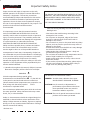
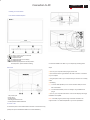
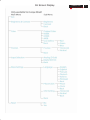
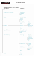
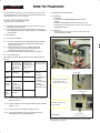
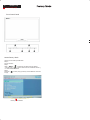
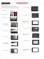
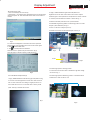
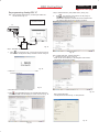
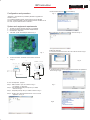
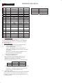
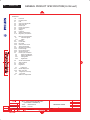
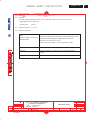
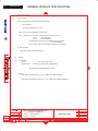
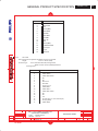
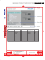
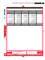
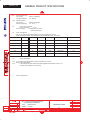
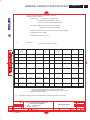
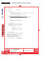
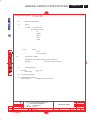
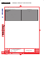
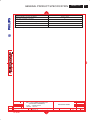
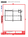
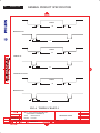
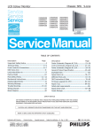
DDC Instructions
25
200WP7 LCD
Go to cover page
Re-programming Digital DDC IC
Step 3: Modify DDC data (verify EDID version, week, year)
Step 1: After initialize alignment box, connecting all cables and
box as shown in Fig. 24
1.
1=DVI connector
2=D-SUB connector
3=Power Plug
Click
(new function) icon from the tool bar, bring up
Step 1 of 9 as shown in Fig. 28 .
EDID45 DDC application provides the function selection and
text change (select & fill out) from Step 1 to Step 9.
To Printer
port
To Printer
port
DC 8~12VDC 8~12V
DC8~12V
8~12V
DC
To Monitor
ToTo
Monitor
D-sub/DVI cable
Monitor
To Monitor
D-sub/DVI
cable
D-sub/DVI
cable
D-sub cable
Power
indicator
3
Power
indicator
To PC
To Monitor
Printer
Port
Fig.24
Step 2: Read DDC data from monitor
1.
Click
icon as shown in Fig. 25 from the tool bar to bring up
the Channels "Configuration Setup" windows as shown in Fig. 26.
Fig. 28
Step 4: Modify DDC data (Monitor Serial No.)
1. Click Next , bring up Fig. 29. Then select Digital Signal as below
Fig. 25
2. Select the DDC2Bi as the communication channel.
As shown in Fig. 26.
Fig. 26
3. Click OK button to confirm your selection.
4. Click
icon (Read EDID function) to read DDC EDID data from
monitor. The EDID codes will display on screen as shown in Fig. 27.
To Printer port
Fig. 27
Fig. 29
2. Click Next to step7, bring up Fig. 30.
- Serial number can be filled up or be changed at this moment.
- Click Finish to exit the Step window.
Fig. 30