1
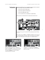
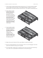
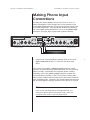
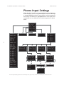
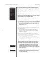
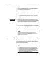
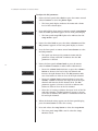
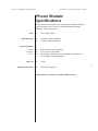
Installation Instructions
& Release Notes
Nº326S
Preamplifier
Phono Modules
Important Safety Instructions
1. Read these instructions
2. Keep these instructions.
3. Heed all warnings.
4. Follow all instructions.
5. Do not use this apparatus near water.
6. Clean only with a dry cloth.
7. Do not block ventilation openings. Install in accordance with the manufacturer’s instructions.
8. Do not install near any heat sources such as radiators, heat registers, stoves, or another apparatus
that produces heat.
9. Do not defeat the safety purpose of the polarized or grounding-type plug. A polarized plug has
two blades with one wider than the other. A grounding-type plug has two blades and a third
grounding prong. The wide blade or third prong is provided for safety. If the provided plug
does not fit into the outlet, consult an electrician for replacement of the obsolete outlet.
10. Protect the power cord from being walked on or pinched, particularly at plugs, convenience
receptacles, or the point where it exits from the apparatus.
11. Only use attachments and accessories specified by the manufacturer.
ii
12.
Use only with the cart, stand, tripod, bracket, or table specified by the manufacturer
or sold with the apparatus. When a cart is used, use caution when moving the
cart/apparatus combination to avoid injury or tip over.
13. Unplug this apparatus during lightning storms or when unused for long periods of time.
14. Refer all servicing to qualified service personnel. Servicing is required when the apparatus has
been damaged in any way, such as when the power cord or plug has been damaged; liquid has
been spilled or objects have fallen into the apparatus; or the apparatus has been exposed to
rain or moisture, does not operate normally, or has been dropped.
15. No naked flame sources, such as candles, should be placed on the apparatus.
16. The power cord is intended to be the safety disconnect device for this apparatus. Ready access
to the power cord should be maintained at all times.
17.
Terminals marked with this symbol may be considered HAZARDOUS LIVE and the
external wiring connected to these terminals requires installation by an INSTRUCTED
PERSON or the use of ready-made leads or cords.
Warning!
To reduce the risk of fire or electric shock, do not expose the apparatus to rain or moisture. Do
not place objects containing liquid, such as vases, on this apparatus.
ESD (Electrostatic Discharge)
Precautions
CAUTION
The following practices minimize possible damage to circuit board assemblies resulting from
electrostatic discharge or improper insertion:
•
Keep circuit board assemblies in their original containers until ready for use.
•
Avoid having plastic, vinyl, or Styrofoam in the work area.
•
Wear an anti-static wrist strap.
•
Discharge personal static before handling circuit board assemblies.
•
Remove and insert circuit board assemblies with care.
•
When removing circuit board assemblies, handle only by non-conductive surfaces. Never
touch open-edge connectors except at a static-free workstation*.
•
Minimize handling of circuit board assemblies.
•
Do not slide circuit board assemblies over any surface.
•
Insert circuit board assemblies with the proper orientation.
•
Use anti-static containers for handling and transporting circuit board assemblies.
iii
FCC Notice
This equipment has been tested and found to comply with the limits for a Class B digital device, pursuant to
part 15 of the FCC Rules. These limits are designed to provide reasonable protection against harmful interference in a residential installation. This equipment generates, uses, and can radiate radio frequency energy and,
if not installed and used in accordance with the instructions, may cause harmful interference to radio communications. However, there is no guarantee that interference will not occur in a particular installation. If
this equipment does cause harmful interference to radio or television reception, which can be determined by
turning the equipment off and on, the user is encouraged to try to correct the interference by one or more of
the following measures:
•
Reorient or relocate the receiving antenna.
•
Increase the separation between the equipment and the receiver.
•
Connect the equipment into an outlet on a circuit different from that to which the receiver is connected.
•
Consult an authorized Mark Levinson dealer or an experienced radio/TV technician for help.
Caution!
Changes or modifications not expressly approved by the party responsible for compliance could
void the user’s authority to operate the equipment.
iv
Canada
This Class B digital apparatus complies with Canadian ICES-003.
Cet appareil numérique de la classe B est conforme à la norme NMB-003 du Canada.
3 Oak Park
Bedford, MA 01730-1413 USA
Telephone:
781-280-0300
Fax:
781-280-0490
www.marklevinson.com
Customer Service
Telephone:
781-280-0300
Sales Fax:
781-280-0495
Service Fax:
781-280-0499
Product Shipments
16 Progress Road
Billerica, MA 01821-5730 USA
Part No. 070-16659 | Rev 0 | 06/04
“Mark Levinson” and the Mark Levinson logo are registered trademarks of
Harman International Industries. U.S. patent numbers and other worldwide
patents issued and pending.
“Madrigal Audio Laboratories” and the Madrigal Audio Laboratories logo are
registered trademarks of Harman International Industries. U.S. patent numbers
and other worldwide patents issued and pending.
©2004 Harman Specialty Group. All rights reserved.
This document should not be construed as a commitment on the part of
Harman Specialty Group. The information it contains is
subject to change without notice. Harman Specialty Group assumes no
responsibility for errors that may appear within this document.
Nº326S Preamplifier Phono Modules
Installation Instructions & Release Notes
Table of Contents
Documentation Conventions . . . . . . . . . . . . . . . . . . . . . . . . .vi
Special Design Features . . . . . . . . . . . . . . . . . . . . . . . . . . . . .1
Unpacking . . . . . . . . . . . . . . . . . . . . . . . . . . . . . . . . . . . . . .2
Configuring & Installing the Phono Modules . . . . . . . . . . . . . .2
Configuration Instructions • Installation Instructions
Making Phono Input Connections . . . . . . . . . . . . . . . . . . . . .9
Phono Input Settings . . . . . . . . . . . . . . . . . . . . . . . . . . . . .10
Name • Bal
Phono Module Specifications . . . . . . . . . . . . . . . . . . . . . . . .15
Notes . . . . . . . . . . . . . . . . . . . . . . . . . . . . . . . . . . . . . . . . .16
v
Installation Instructions & Release Notes
Mark Levinson
Documentation
Conventions
This document contains hardware installation instructions and
software release notes for the Nº326S Preamplifier Phono Modules.
Refer to the Nº326S Preamplifier Owner’s Manual for general safety, installation, and operation instructions.
Appears on the component to indicate the
presence of uninsulated, dangerous voltages
inside the enclosure – voltages that may be
sufficient to constitute a risk of shock.
Appears on the component to indicate
important operation and maintenance
instructions included in the accompanying
documentation.
Appears on the component to indicate
compliance of with the EMC (Electromagnetic
Compatibility) and LVD (Low-voltage
Directive) standards of the European
Community.
vi
Calls attention to an ESD (electrostatic
discharge) procedure, practice, condition, or
the like that, if not correctly performed or
adhered to, could result in damage to circuit
board assemblies.
WARNING
Calls attention to a procedure, practice,
condition, or the like that, if not correctly
performed or adhered to, could result in
personal injuries or death.
CAUTION
Calls attention to a procedure, practice,
condition, or the like that, if not correctly
performed or adhered to, could result in
damage or destruction to part or all of the
component.
Note
Calls attention to information that is
essential to highlight.
Nº326S Preamplifier Phono Modules
Installation Instructions & Release Notes
Special Design Features
•
Seamless Integration
When the phono modules are installed, the stereo input
connector labeled 7 becomes the phono input connector,
accepting input signals from most phono cartridges. As a result,
the phono modules benefit from all the high-performance
power supply and noise suppression features designed into the
Nº326S, allowing them to deliver exceptional sound quality.
Each phono module relies on the same low-noise power supply
as the main audio circuits in addition to its own local, lownoise, high-speed voltage regulators.
•
Flexible Configuration
Multiple loading and input gain options make the phono
modules compatible with most phono cartridges, including
moving-coil, moving-magnet, high-output, and low-output
designs. Three adjustable jumpers provide 200Ω or 47kΩ
resistive loading; 0 or 10nF capacitive loading; and 40 or
60dB input gain. Convenient gold-plated, solder-less screw
terminals accommodate custom loading.
•
Balanced Design
Available on a proprietary Mark Levinson-designed stereo RCA
connector, the phono input provides the same common
mode noise rejection benefits as a balanced XLR connector.
The input gain stage produces a symmetrical pair of opposite
polarity signals, based solely on voltage differences present at
the input. Each balanced signal follows the same signal path,
including identical RIAA equalization.
•
Instrumentation Amplifier Stage
Gain is distributed over two stages, allowing ample bandwidth
and open-loop gain for superior performance – even at the
60dB input gain required for moving-coil phono cartridges.
Introduced with the Nº38, the instrumentation amplifier stage
resolves tiny electrical signals from potentially noisy
environments. This method offers high common mode noise
rejection without the limitations of transformer-based designs.
•
Precise RIAA Equalization
A balanced pair of RIAA equalization circuits follows the input
gain stages. These circuits include a filter constructed with
0.5% non-inductive metal-film resistors and 2.5% stacked-film
capacitors as well as a subsonic filter below 10Hz for
uncompromised RIAA curve accuracy.
•
Arlon Circuit Boards
Arlon® circuit boards respond more quickly to transient signals in both the high- and low-frequency regions. Arlon also
presents a deeper imaging that reveals more of the subtle
1
Installation Instructions & Release Notes
Mark Levinson
nuances of a recording, imparts a more engaging texture to
the high frequencies, and presents more of the ambience of a
recording. All of these properties work together to yield a
sonic signature that is wider, deeper, warmer, and clearly superior.
Unpacking
CAUTION
FOLLOW PRESCRIBED ESD PRECAUTIONS (page iii).
When unpacking the phono modules:
•
Save all packing materials for possible future shipping needs.
•
Inspect the phono modules for signs of damage during shipment. If damage is discovered, contact an authorized Mark
Levinson dealer for assistance making the appropriate claims.
•
Locate and remove all items from the packing carton. Contact
an authorized Mark Levinson dealer if the packing carton does
not include all of the items listed in the table below.
2
Item
Quantity
Nº326S Phono Modules
2
Anti-static wrist strap
1
1/8-inch hex-key
1
Flat-blade screwdriver
1
Configuring & Installing
the Phono Modules
The phono modules require special care and handling during
configuration and installation to ensure optimal performance. Pay
particular attention to precautions that appear in this section, as
well as to the Important Safety Instructions (page ii) and ESD
Precautions (page iii). Damage caused during configuration or
installation may void the manufacturer’s warranty and/or
standard repair policies.
NOTE: Nº326S phono modules may be used with the Nº320S
preamplifier without modification.
Nº326S Preamplifier Phono Modules
Configuration
Instructions
Installation Instructions & Release Notes
The phono modules must be optimized to work with the associated
phono cartridge. Each phono module includes:
•
1 adjustable resistive load jumper
•
1 adjustable capacitive load jumper
•
1 adjustable input gain jumper
•
2 screw terminals that accommodate custom loads
These features are identified in the illustration shown below.
1 2 3
RL =47K RL =200
C L =0nF C L=10nF
G=40db G=60db
JUMPER SETTINGS
CLOSED
OPEN
4
CUSTOM
TERMINATION
No.326S PHONO
P10
3
The numbered items in the phono module illustration shown above correspond with the
numbered items that begin on the next page. The left and right-channel phono modules
are identical.
Each jumper can be OPEN or CLOSED, depending on the needs of
the associated phono cartridge. Select one setting for each jumper.
Refer to the illustrations shown below for recommendations.
CUSTOM
TERMINATION
OPEN
CUSTOM
TERMINATION
JUMPER SETTINGS
CLOSED
When the phono modules are shipped, all
jumpers are CLOSED as shown in the illustration
above. In general, it is recommended to leave
all jumpers CLOSED for most low-output,
moving-coil phono cartridges.
P10
P10
RL =47K RL =200
C L =0nF C L=10nF
G=40db G=60db
OPEN
JUMPER SETTINGS
CLOSED
RL =47K RL =200
C L =0nF C L=10nF
G=40db G=60db
In general, it is recommended to OPEN all
jumpers for most high-output, moving-magnet
phono cartridges.
Installation Instructions & Release Notes
Mark Levinson
1. Resistive Load (RL) Jumper
Moving-coil phono cartridges often benefit from a low-value
resistor termination.
•
Leave the resistive load jumper CLOSED to place a 200Ω
resistor load on the phono input.
•
OPEN the resistive load jumper to place a 47kΩ resistor
load on the phono input.
2. Capacitive Load (CL) Jumper
Low-impedance moving-coil phono cartridges often benefit
from a capacitor termination.
•
Leave the capacitive load jumper CLOSED to place a
10nF capacitor load on the phono input.
•
OPEN the capacitive load jumper to place no capacitor
load on the phono input.
Note
•
When both the capacitive and resistive load jumpers
are OPEN, custom loads are in parallel with the 47KΩ
input resistor. This parallel combination becomes more
significant as custom loads exceed 5KΩ in value. Use
the following formula if an exact termination value is
desired: [RL=1/(1/custom load+1/47KΩ)].
•
Contact the phono cartridge manufacturer for specific
capacitive and resistive loading recommendations.
4
3. Input Gain (G) Jumper
Low-output (<5mV) phono cartridges often benefit from more
input gain. High-output (>5mV) phono cartridges often benefit
from less input gain.
•
Leave the input gain jumper CLOSED to place 60dB of
gain on the phono input.
•
OPEN the input gain jumper to place 40dB of gain on the
phono input.
4. Custom Load Screw Terminals
•
Fasten the desired value resistor and/or capacitor to the screw
terminals to place a custom load on the phono input.
•
In some cases, manufacturers recommend resistive loads
other than 200Ω or 47kΩ. The screw terminals accommodate
custom loads below 47kΩ.
Nº326S Preamplifier Phono Modules
Installation
Instructions
Installation Instructions & Release Notes
The following materials are needed to install the phono modules:
Item
Quantity
Nº326S Preamplifier
1
Nº326S phono modules
2
Anti-static wrist strap
1
1/8-inch hex-key
1
Flat-blade screwdriver
1
Note
The phono modules must be configured BEFORE installation.
WARNING
THESE SERVICE INSTRUCTIONS ARE ONLY INTENDED
FOR USE BY QUALIFIED PERSONNEL. DO NOT PERFORM ANY SERVICING UNLESS QUALIFIED TO DO SO.
REFER TO THE IMPORTANT SAFETY INSTRUCTIONS
(PAGE ii) PRIOR TO PERFORMING ANY SERVICE.
CAUTION
•
NEVER MAKE OR BREAK CONNECTIONS TO THE
Nº326S UNLESS IT AND ALL ASSOCIATED
COMPONENTS ARE POWERED OFF AND
DISCONNECTED FROM ELECTRICAL OUTLETS.
•
DISCONNECT THE POWER CORD FROM BOTH THE
Nº326S AND THE ELECTRICAL OUTLET BEFORE
INSTALLING THE PHONO MODULES.
Before installing the phono modules:
•
Power off the Nº326S and all associated components.
•
Disconnect the power cord from the ~ac input connector
AND the electrical outlet.
•
Disconnect the Nº326S from all associated components.
5
Installation Instructions & Release Notes
Mark Levinson
To install the phono modules:
1. Place the Nº326S upside-down on a flat, level surface such as a
table or workbench. Do not place the Nº326S on a surface that
is unstable.
Note
Perform these installation instructions at a static-free
workstation to avoid damaging circuit boards. Damage
resulting from failure to work at a static-free workstation
may void the manufacturer’s warranty and/or standard
repair policies.
2. Use the provided 1/8-inch hex-key to remove the four screws
that secure the feet and the top cover. These screws are identified in the illustration shown below (left).
3. Place the Nº326S upright on the work surface. Take care to
avoid “dropping” the Nº326S on the work surface once the
feet are removed.
4. Remove the top cover from the Nº326S, gently sliding it
toward the rear panel as shown in illustration below (right).
6
5. Put on the provided anti-static wrist strap.
6. Remove the phono modules from their ESD protective bags.
Screws
Nº326S Preamplifier Phono Modules
Installation Instructions & Release Notes
7. Refer to illustrations shown below to locate the following:
A. Phono module insertion slots
B. Phono module mounting terminals
C. Location P300 (plug)
D. Location P500 (plug)
E. Location P10 (socket)
F.
Phono module mounting bracket and screw
CUSTOM
TERMINATION
E
OPEN
P10
F
RL =47K RL =200
C L =0nF C L=10nF
G=40db G=60db
No.326S PHONO
A
JUMPER SETTINGS
CLOSED
B
D
C
The lettered items in the illustrations shown above correspond with the lettered items listed in step 7 (above) and referenced in steps 8,
9, 10, and 11.
8. Gently slide one of the phono
modules into the left-most
insertion slot (A) as shown in
the illustration to the right.
The socket at location P10 (E)
on the phono module will
connect with the plug at
location P500 (D) on the
main circuit board, and the
phono module mounting
bracket (F) will align with the
mounting terminal (B) on the
main circuit board.
7
Installation Instructions & Release Notes
Mark Levinson
9. Align the phono module mounting bracket mounting screw (F) with the mounting terminal
(B) on the main circuit board. Then, use the supplied flat-blade screwdriver to secure the
phono module to the main circuit board. Take care not to “over-tighten” the mounting screw.
10. Gently slide the second
phono module into the
right-most insertion slot
(A) as shown in the
illustration to the right.
The socket at location P10
(E) on the phono module
will connect with the
plug at location P300 (C)
on the main circuit board,
and the phono module
mounting bracket (F) will
align with the mounting
terminal (B) on the main
circuit board.
8
11. Align the phono module
mounting bracket mounting screw (F) with the
mounting terminal (B) on
the main circuit board.
Then, use the
supplied flat-blade
screwdriver to secure
the phono module to the
main circuit board. Take
care not to “over-tighten”
the mounting screw.
12. Replace the top cover from the Nº326S, gently sliding it toward the front panel.
13. Place the Nº326S upside-down on the work surface. Take care to avoid “dropping” the Nº326S
on the work surface once the top cover is replaced.
14. Use the provided 1/8-inch hex-key to replace the four screws that secure the feet and the top
cover. These screws are identified in the illustrations at the bottom of page 6.
Nº326S Preamplifier Phono Modules
Installation Instructions & Release Notes
Making Phono Input
Connections
Installing the phono modules allows the Nº326S to serve as a
phono preamplifier. When shipped the Nº326S includes seven
stereo input connectors that accept line-level input signals from
associated components. Once the phono modules are installed,
the stereo input connector labeled 7 serves as the phono input
connector, accepting input signals from a phono cartridge.
MARK LEVINSON
PREAMPLIFIER Nº326S
S/N
RIGHT CHANNEL
record outputs
communication
RS-232
record outputs
trigger ir
output input
Made in the U.S.A.
~ac mains
LEFT CHANNEL
inputs
main outputs
main outputs
inputs
2
1
slave in
1
2
5
4
phono
ground
1
2
3
4
5
6
7
7
6
3
2
1
2
1
Associated Phono Cartridge
To connect the Nº326S to a phono cartridge:
•
Connect the associated phono cartridge cable to the stereo
input connectors labeled 7 as shown in the illustration
above.
The Nº326S also includes a phono ground connector, which
provides an earth-reference ground connection for the associated
phono cartridge. Connecting the associated phono cartridge
grounding wire to the phono ground connector grounds the
associated phono cartridge to the Nº326S chassis, which sometimes reduces audible hum and other noise that results from multiple grounding paths. Otherwise, the ground connection between
the associated phono cartridge and the Nº326S chassis is isolated.
Note
Listen to the associated phono cartridge both with and
without the phono ground connection. Then, select the
connection that results in the best performance.
9
Installation Instructions & Release Notes
Mark Levinson
Phono Input Settings
When the phono modules are not installed, the stereo input connector labeled 7 serves as the phono input connector. This input
is renamed PHONO within the setup menu, and new parameters
and settings are added to its Set Inputs menu. Other inputs and
setup menus are not affected. The revised setup menu is shown
below.
No326S Setup
Set Inputs
Teach IR
Mute = -20.0
MaxVol= 80.0
Trig.= 12v,L
Sw 1.00 B.18
10
VOLUME UP
VOLUME DOWN
SELECT NEXT
SELECT PREV
INTENSITY
MUTE KEY
MONO KEY
POLARITY KEY
STANDBY KEY
ENTER KEY
SETUP KEY
BALANCE KEY
EXIT STANDBY
GO STANDBY
GO INPUT 1
GO INPUT 2
GO INPUT 3
GO INPUT 4
GO INPUT 5
GO INPUT 6
GO INPUT 7
GO MUTE
GO UNMUTE
GO BALANCE
EXIT BALANCE
DISPLAY OFF
DISPLAY DIM
DISPLAY HALF
DISPLAY FULL
-80.0 to -10.0
40.0 to 80.0
12v,L
5v,P
Set
Set
Set
Set
Set
Set
Set
Name=INPUT 1
Gain= +6 dB
Offset= 0.0
Rec.Out=NONE
Name=INPUT 2
Gain= +6 dB
Offset= 0.0
Rec.Out=NONE
Name=INPUT 3
Gain= +6 dB
Offset= 0.0
Rec.Out=NONE
Name=INPUT 4
Gain= +12 dB
Offset= 0.0
Rec.Out=NONE
Input
Input
Input
Input
Input
Input
Phono
1
2
3
4
5
6
7
Name=INPUT 5
Gain= +12 dB
Offset= 0.0
Rec.Out=NONE
Name=INPUT 6
Gain= +12 dB
Offset= 0.0
Rec.Out=NONE
Name= PHONO
Gain= +12 dB
Offset= 0.0
Bal= <-0.0->
Rec.Out=NONE
+0 dB
+6 dB
+12dB
+18dB
-20.0 to +20.0
<-6.0 to 6.0->
NONE
#1
#2
BOTH
The front panel display provides one-line viewing of the setup menus shown here, indicating the current menu item.
Nº326S Preamplifier Phono Modules
Installation Instructions & Release Notes
The table below indicates all Set Inputs menu parameters available
for the phono input.
Default
Parameter
Setting
Possible
Settings
Name
PHONO
PHONO, PH/MC, unused
Gain*
+12dB
+0dB, +6dB, +12dB, +18dB
Offset*
0.0dB
–20.0 to +20.0dB
Bal
0.0
0.0 to 6.0 (left or right)
Rec.Out*
NONE
NONE, #1, #2, BOTH
*
Name
PHONO, PH/MC, unused
Custom Names List
PHONO
PH/MC
unused
These parameters continue to function as described in the Nº326S Owner’s Manual.
Determines the name of the phono input connector (7). The
factory-default input name is PHONO. Two methods are available
for customizing input names: the custom names list and the
character list.
When the phono modules are not installed, the phono input
does not have access to the same custom input names as the other
stereo inputs. The custom names list shown at the left provides
convenient access to the three custom input names available for
the phono input. The table below indicates the intended use of
these custom input names.
Custom Name
Description
PHONO
Indicates that the phono input connector is
associated with a moving-magnet phono
cartridge.
PH/MC
Indicates that the phono input connector is
associated with a moving-coil phono
cartridge.
Unused
Indicates that the phono input connector is
not in use, removing it from select knob or
select ± button scrolling.
11
Installation Instructions & Release Notes
Character List
A
D
G
J
M
P
S
V
Y
1
7
+
(
a
d
g
j
m
p
s
v
y
2
8
–
)
B
E
H
K
N
Q
T
W
Z
3
9
.
,
b
e
h
k
n
q
t
w
z
4
&
/
_
C
F
I
L
O
R
U
X
_
5
‘
:
c
f
i
l
o
r
u
x
0
6
*
?
Mark Levinson
When the phono modules are installed, the phono input has
access to the same character list as the other stereo inputs. This
character list is shown at the left. A custom input name entered
with the character list replaces the PH/MC name on the custom
names list. In other words, the character list is only available
when the PH/MC custom name is selected.
To change the name of phono input:
1. Rotate the front panel select knob or press the remote control
select ± buttons to select the phono input.
•
The front panel display indicates the name and volume
level of the selected input.
2. Press and hold the front panel or remote control setup button
until the Name parameter appears on the front panel display.
•
The front panel setup LED lights red to indicate that the
setup menu is open.
3. Press the front panel or remote control enter button to select
the Name parameter.
•
12
The equal sign between the parameter name and the
parameter setting will blink to indicate that the Name
parameter is selected.
4. Rotate the front panel volume knob or press the remote
control volume ± buttons to scroll through all custom input
names included on the custom names list.
•
When the PH/MC name appears on the front panel
display, the name will blink as shown at the left to indicate
that the character list is available.
5. When the desired custom input name appears on the front
panel display, press the enter button to select this custom
input name.
•
If the PHONO or unused input name was selected, the
SAVING DATA message will appear on the front panel
display as shown to the left to indicate that the new input
name is being saved.
•
If the PH/MC input name was selected, the first character
in the input name (“P”) will blink as shown to the left to
indicate that a new custom input name can be entered
with the character list.
SAVING DATA
Name=_H/MC
Nº326S Preamplifier Phono Modules
Installation Instructions & Release Notes
6. Rotate the volume knob or press the volume ± buttons to
scroll through all available characters.
7. When the desired character appears on the front panel display,
press the enter button to select this character. The cursor will
automatically advance to the next character space.
•
SAVING DATA
Custom input names can consist of up to 7 characters,
including letters, numbers, punctuation marks, and blank
spaces.
8. Repeat steps 6 and 7 until all seven characters have been
entered. When the seventh character is selected, the SAVING
DATA message will appear on the front panel display as
shown at the left to indicate that the new input name is being
saved.
9. Press and release the setup button to close the setup menu.
•
The front panel setup LED is not lit when the setup
menu is closed.
13
Note
The factory-default input name must be restored one
character at a time using the character list (unless factorydefault settings are restored).
Bal
0.0 to 6.0 (left or right)
Controls the left-to-right channel balance of the phono input
connector. In some cases, phono cartridges introduce slight level
differences between the left and right channels. Adjustable in
0.1dB increments between 0.0 and 6.0dB, the Bal parameter can
be used to compensate for these differences, ensuring optimal
stereo balance between channels.
Note
•
The Bal parameter does not affect record output levels.
•
The Bal parameter affects only the phono input connector.
It should not be confused with the Balance control,
which affects all inputs, adjusting the left-to-right channel
balance of the main output connectors.
Installation Instructions & Release Notes
Mark Levinson
To adjust the Bal parameter:
PHONO
(7)
1. Rotate the front panel select knob or press the remote control
select ± buttons to select the phono input.
•
Name= PHONO
2. Press and hold the front panel or remote control setup button
until the Name parameter appears on the front panel display.
•
Bal= <-0.0->
The front panel display indicates the name and volume
level of the selected input.
The front panel setup LED lights red to indicate that the
setup menu is open.
3. Rotate the select knob or press the select ± buttons until the
Bal parameter appears on the front panel display as shown.
4. Press the front panel or remote control enter button to select
the Bal parameter.
•
The equal sign between the parameter name and the
parameter setting will blink to indicate that the Bal
parameter is selected.
5. Rotate the front panel volume knob or press the remote
control volume ± buttons to make balance adjustments:
14
•
Rotate the volume knob clockwise or press the volume +
button to decrease the level of the left channel and
increase the right-channel level. The Bal parameter indicates that balance is offset in favor of the right channel.
•
Rotate the volume knob counterclockwise or press the
volume – button to decrease the input level of the right
channel and increase the left-channel level. The Bal
parameter appears as shown to the left to indicate that
balance is offset in favor of the left channel.
•
Select the 0.0 setting to balance the input levels of the left
and right channels. The Bal parameter appears as shown
to the left to indicate that balance is centered between the
left and right channels.
Bal= 6.0--->
Bal= <---6.0
Bal= <-0.0->
6. When the desired setting appears on the front panel display,
press the enter button to select this setting.
7. Press and release the setup button to close the setup menu.
•
The front panel setup LED is not lit when the setup
menu is closed.
Nº326S Preamplifier Phono Modules
Installation Instructions & Release Notes
Phono Module
Specifications
Unless otherwise specified, these specifications indicate nominal
values measured over a 20Hz to 20kHz bandwidth through
balanced (XLR) connections.
Gain
•
40 or 60dB @ 1kHz
Input Overload
•
•
>100mV @ 1kHz, 40dB gain
200Ω or 47kΩ (user-selectable)
Custom
•
•
•
THD + N
•
<0.02%
Frequency Response
•
±1dB (RIAA response)
>10mV @ 1kHz, 60dB gain
Input Impedance
Resistive
Capacitive
0 or 10nF (user-selectable)
Gold-plated, solder-less screw terminals are available for
user-installed load terminations.
15
Specifications are subject to change without notice.
Installation Instructions & Release Notes
Notes
16
Mark Levinson
Nº326S Preamplifier Phono Modules
Installation Instructions & Release Notes
Notes
17
Installation Instructions & Release Notes
Notes
18
Mark Levinson
3 Oak Park, Bedford, MA, 01730-1413 USA | Telephone: 781-280-0300 | Fax: 781-280-0490 | www.marklevinson.com
Customer Service: Telephone: 781-280-0300 | Sales Fax: 781-280-0495 | Service Fax: 781-280-0499
Product Shipments: 16 Progress Road, Billerica, MA 01821-5730 USA
Part No. 070-16659 | Rev 0 | 06/04