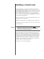
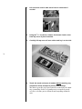
1
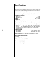
Owner’s Manual
Nº32
Reference
Phono Modules
R
Madrigal Audio Laboratories
WARNING: TO REDUCE THE RISK OF FIRE OR ELECTRIC SHOCK, DO
NOT EXPOSE THIS APPLIANCE TO RAIN OR MOISTURE.
CAUTION
RISK OF ELECTRIC SHOCK
DO NOT OPEN
CAUTION: TO REDUCE THE RISK OF ELECTRICAL SHOCK, DO
NOT REMOVE COVER. NO USER-SERVICEABLE PARTS INSIDE.
REFER SERVICING TO QUALIFIED PERSONNEL.
The lightning flash with arrowhead symbol, within an equilateral triangle, is intended to alert
the user to the presence of uninsulated “dangerous voltage” within the product’s enclosure that
may be of sufficient magnitude to constitute a risk of electric shock to persons.
The exclamation point within an equilateral triangle is intended to alert the user to the presence
of important operating and maintenance (servicing) instructions in the literature accompanying
the appliance.
Marking by the “CE” symbol (shown left) indicates compliance of this device with the EMC
(Electromagnetic Compatibility) and LVD (Low Voltage Directive) standards of the European
Community.
NOTICE
This equipment has been tested and found to comply with the limits for a Class B digital device, pursuant to
Part 15 of the FCC Rules. These limits are designed to provide reasonable protection against harmful
interference in a residential installation. This equipment generates, uses and can radiate radio frequency
energy and, if not installed and used in accordance with the instructions, may cause harmful interference to
radio communications. However, there is no guarantee that interference will not occur in a particular
installation. If this equipment does cause interference to radio or television reception, which can be
determined by turning the equipment on and off, the user is encouraged to try to correct the interference by
one or more of the following measures:
•
•
•
•
Reorient or relocate the receiving antenna;
Increase the separation between the equipment and the receiver;
Connect the equipment into an outlet on a circuit different from that to which the receiver is connected;
Consult the dealer or an experienced radio/TV technician for help.
CAUTION: Changes or modifications to this equipment not expressly approved by the manufacturer could
void the user’s authority to operate the equipment.
The information contained in the manual is subject to change without notice. The most current version of this
manual will be posted on our web site at http://www.madrigal.com.
Important Safety Instructions
Please read all instructions and precautions carefully and completely before operating your Mark
Levinson® preamplifier.
1. ALWAYS disconnect your entire system from the AC mains before connecting or disconnecting any cables, or when cleaning any component.
2. This product must be terminated with a three-conductor AC mains power cord which
includes an earth ground connection. To prevent shock hazard, all three connections
must ALWAYS be used.
3. AC extension cords are not recommended for use with this product.
4. NEVER use flammable or combustible chemicals for cleaning audio components.
5. NEVER operate this product with any covers removed.
6. NEVER wet the inside of this product with any liquid.
7. NEVER pour or spill liquids directly onto this unit.
8. NEVER block air flow through ventilation slots or heatsinks.
9. NEVER bypass any fuse.
10. NEVER replace any fuse with a value or type other than those specified.
11. NEVER attempt to repair this product. If a problem occurs, contact your Mark
Levinson® retailer.
12. NEVER expose this product to extremely high or low temperatures.
13. NEVER operate this product in an explosive atmosphere.
14. ALWAYS keep electrical equipment out of the reach of children.
15. ALWAYS unplug sensitive electronic equipment during lightning storms.
From all of us at Madrigal Audio Laboratories, thank you for choosing the Mark
Levinson Nº32 Reference Phono Preamplifier Modules.
4
A great deal of effort went into the design and construction of these precision
devices. Used properly, they will give you many years of enjoyment.
Table of Contents
Special Design Features of the Nº32 Reference Preamplifier ....... 6
modular approach .............................................................................. 6
input connections .............................................................................. 6
input loading network ........................................................................ 6
ac regenerated power supply ............................................................. 7
fully balanced design .......................................................................... 7
instrumentation amplifier topology ..................................................... 8
high accuracy RIAA equalization ......................................................... 9
DC servo stabilized ............................................................................. 9
component selection .......................................................................... 9
Unpacking .............................................................................. 10
unpacking ........................................................................................ 10
Operating Voltage ................................................................... 11
Warm up & break-in period ............................................................... 11
Installing the Nº32 Reference Phono Preamplifier Modules ...... 12
material needed ............................................................................... 13
installation procedure ....................................................................... 13
Customizing Your Nº32 ........................................................... 19
setup overview ................................................................................. 19
the menu system .............................................................................. 19
configuring phono inputs ................................................................. 20
naming a phono input ..................................................................... 21
setting the phono gain ..................................................................... 21
setting (line) gain ............................................................................. 22
setting the offset .............................................................................. 22
setting the balance ........................................................................... 23
setting the 20 Hz filter ...................................................................... 23
setting the resistive load ................................................................... 23
setting the capacitive load ................................................................ 24
Installing a Custom Load ......................................................... 25
Care and Maintenance ............................................................. 29
U.S. and Canadian Warranty .................................................... 30
90-day limited warranty .................................................................... 30
five year extended warranty ............................................................. 30
Obtaining Service .................................................................... 31
Specifications .......................................................................... 32
Installation Notes .................................................................... 33
5
Special Design Features of the
Nº32 Reference Preamplifier
modular approach
The Nº32 Reference Preamplifier and Reference Phono Preamplifier
Modules were designed together. All the high performance power supply, extensive control and high isolation input circuitry that characterizes the Nº32 Reference Preamplifier allows the purpose-built phono
modules to perform at a extraordinarily high level.
Each channel of the Nº32 reference phono preamplifier is a removable
module. Each module is shielded in a metal box, not simply for mechanical handling, but for the extraordinary noise shielding properties
that only a fully enclosed Mu-metal case can provide.
input connections
The phono preamp has input connections for two phono sources.
These inputs benefit from Madrigal’s “virtually unplugged” input
switching topology, where ground as well as hot connections of
unselected inputs are broken to eliminate ground current flow between
components. Shorting the unselected signal insures superb isolation
between phono inputs. Low level phono signals pass through only the
highest-grade Madrigal RCA connector or Swiss-made Neutrik XLR
connector; hermetically-sealed, rhodium-contact reed relays; and a
Teflon-insulated flat conductor interconnect cable before reaching the
active preamplifier circuitry.
input loading network
Optimum input loading for your phono cartridge is essential to achieving the performance your cartridge manufacturer intended. The Nº32
reference phono preamplifier makes getting the most from your phono
system more convenient (and more likely) than ever. A network of resistor and capacitor terminations, switched by the same reed relays as
above (specifically optimized for ultra-low signals), gives a full range of
loading options that are accessible from both the Nº32 front panel and
its remote control.
6
Available resistor load values are 3.3Ω, 5Ω, 7.7Ω, 10Ω, 33Ω, 50Ω, 77Ω,
100Ω, 330Ω and 47kΩ.
Available capacitor loads values are 0pF, 50pF, 100pF, 150pF, 200pF,
250pF, 300pF, 350pF and .01uF.
All the provided load termination components are the highest quality,
plate-style, thin film resistors or polypropylene film capacitors. In addi-
tion, optional custom termination is provided via a pair of gold-plated
terminal posts within each phono module. No soldering is necessary
when using these binding posts.
ac regenerated
power supply
The foundation upon which any audio component is built is the power
supply. Without an extremely clean, noise-free power supply, no audio
circuit can live up to its potential.
Unfortunately, we live in a world in which the quality of AC mains
power is increasingly in question. The modern conveniences upon
which we have become so dependent introduce line noise, spikes, and
various other irregularities. Everything from refrigerators to televisions
and computers inject their peculiar contaminations back onto the AC
line, making it increasingly difficult for a high performance audio component to live up to its potential.
In the Nº32, we solve this problem by becoming our own power utility.
Strange as this sounds, it is effectively true. There are two independent,
unusually high quality power supplies dedicated to the two audio channels. The DC power from these supplies is then used to power a special
power amplifier that is fully optimized for reproducing only one frequency: 400 Hz. This extremely pure 400 sine wave is then rectified, filtered, and regulated again to create extraordinarily pure DC power for
the use of the critical preamplifier circuits.
By creating our own dedicated 400 Hz AC power and then using that to
create “second generation” DC power for the audio circuitry, we keep
the contamination of the modern electrical grid at a safe distance from
the sensitive audio circuits we look to for our musical enjoyment.
The phono preamp modules use the same AC-regenerated power supply used by the rest of the Nº32 reference preamp. By designing the
preamp module inside the Nº32 preamp, we were able to integrate
power, ground and signal distribution with the line level preamplifier
as if the phono preamplifier was simply another stage of the overall
preamplifier circuitry.
Locally, a discrete, high-performance regulator provides each module
with a fast-response, low noise ±15 supply voltage. A multilayer Arlon
25N printed circuit board with extensive ground and power plane construction carries the regulated power to the active circuitry.
fully balanced design
Fully balanced circuitry is more than a tradition at Madrigal. The performance advantages are as clear on the test bench as they are in the listening room. Logic dictated that we offer the best performance avail-
7
able from our balanced circuitry by including a balanced XLR input
connector version of the phono preamplifier modules.
No32 XLR phono module
recommended wiring
NC
1
2
LEFT +
3
LEFT -
TONE ARM GROUND
NC
1
2
3
RIGHT +
RIGHT -
Combined with a shielded, twisted pair cable from cartridge to preamp,
the XLR input phono preamp offers the ultimate in noise rejection and
low level signal resolultion. (An RCA-equipped version is also available
for wider compatibility with existing phono cables.)
8
Madrigal uses a fully balanced implementation in its phono preamplifier. The gain stage produces a perfectly symmetrical pair of oppositepolarity signals, based solely on the difference voltage appearing at the
amplifier input. Each half of the balanced signal sees identical signal
path and circuitry from input to output. The RIAA equalization stage
and even the DC servo is duplicated for each signal half. (A single resistor change on the input amplifier would let each channel operate as a
stereo pair of phono preamplifiers.)
The balanced output signal from the phono preamp is received on the
Nº32 audio input selector board with the same treatment as a line level
balanced input.
instrumentation
amplifier topology
The classic method of resolving tiny electrical signals from potentially
noisy environments is called an “instrumentation amplifier.” The fully
balanced, input to output instrumentation amp—first pioneered in the
high end audio business in the Nº38 family of line-level preamplifiers—is the ideal foundation on which to build a high performance
phono preamp.
The industry’s lowest noise amplifiers implement the input side of the
phono circuit. Gain is distributed over two stages with ample band-
width and open loop gain to provide uncompromised performance
even at the 60db of gain required by a moving coil preamplifier. The
instrumentation amplifier stage offers high common mode rejection, a
noise-cancellation feature usually limited to transformer-based designs,
while avoiding the serious limitations of those same designs.
high accuracy
RIAA equalization
A balanced pair of active RIAA equalization circuits follows the gain
stages. The filter is built with 0.1%, plate style (non-inductive), thin
film resistors and 1%, stacked film, polypropylene capacitors. This
yields less than 0.1db deviation from the ideal RIAA curve. The user
may switch an additional 20Hz high pass filter into the circuit. This filter effectively removes the subsonic noise common to many turntable
configurations. The filter conforms to the RIAA/IEC phono equalization curve.
DC servo stabilized
Any potential for DC output from the phono preamp is nulled out by
an active DC servo. The servo is implemented with low noise, high performance op-amps and film capacitors.
component selection
As with the rest of the components in the Nº32, the selection process
involved many hours of controlled listening tests above and beyond the
usual measurements and lab work. Some examples of the selections include:
• Signal path resistors are 0.1% tolerance, non-inductive (platestyle), thin-film parts.
• Signal path capacitors are also non-inductive (stacked construction), either polypropylene or polyester in parallel polypropylene
film caps.
• The preamp circuit board is four layer, Arlon™ N25 (an ultra
high speed, low loss material) construction.
• Even non-signal path parts are film resistors and caps for best
long-term stability.
• Low level signal interconnect is a flat conductor, Teflon™ insulated balanced cable, soldered at both ends.
• Low level signal relays are a rhodium contact, hermeticallysealed reed type, optimized for ultra-low signal levels.
• The entire module is fully enclosed in a conetic mu-metal shield
box for ultimate low frequency noise isolation.
9
Unpacking
Warning!
Do not attempt to use your Nº32 Reference Phono
modules unless your Nº32 Controller is using version
1.03 (or greater) of its operating software. Prior to
installation, check your software by pressing Setup and
turning the Select knob one click to the left, and
reading the resulting display.
If you need new software, please contact your
authorized Mark Levinson dealer.
unpacking
10
Unpack your Nº32 Reference Phono Preamplifier modules and keep all
packing materials for future transport. Locate and remove all accessory
items from the shipping carton. Accessories include:
1
1
1
1
2
wrist strap for ESD protection
5⁄32" hex key
7⁄64" hex driver
5⁄64" hex driver
10-32 socket head cap screws
You will also need the 3⁄32" hex driver that came with your Nº32 Reference Preamplifier in order to open the main Preamplifier unit.
Operating Voltage
The Nº32 Reference Preamplifier is set at the factory (internally) for
100V, 120V, 230V, 220V, or 240V AC mains operation @ 50 or 60Hz.
(230V/50Hz only in European Union countries, in compliance with CE
regulations.) This voltage setting cannot be changed by the user.
Make sure that the label near the AC receptacle of the Nº32 Controller
indicates the correct AC operating voltage for your location.
If the voltage indicated on your Nº32 Controller is incorrect, or if you
wish to change the AC operating voltage of your Nº32 as the result of
moving to a different country than the one in which you purchased
your preamplifier, see your Mark Levinson dealer.
The Nº32 is easily powered by a normal 15-ampere AC mains line. If
other devices are also powered from the same AC line, their additional
power consumption should be taken into account.
Caution!
Warm up &
break-in period
It is extremely important that all components in your
system be properly grounded. Do not defeat a threeprong AC cords with “ground-lifter” or “cheater”
adaptors, as doing so may allow dangerous voltages to
build up between components. The presence of these
voltages would pose a threat to both your person and
your equipment.
Although your Mark Levinson Nº32 Reference Preamplifier delivers
outstanding performance straight out of the box, you should expect to
hear it continue to improve as it reaches its normal operating temperatures and its various components “break-in.” It has been our experience
that the greatest changes occur within the first 25-50 hours, but that
the preamplifier will continue to improve in sound quality for about
300 hours, after which time it remains quite constant.
The only exception to this rule is if power is removed from the unit, allowing it to cool down. In this case you should expect a brief warm-up
period before the preamplifier’s sound quality is at its best. (Fortunately, you do not have to repeat the full 300-hour break-in period.)
11
Installing the Nº32 Reference
Phono Preamplifier Modules
Important!
Installation of the Nº32 Reference Phono Preampllifier
Modules should be done by a qualified and authorized
Mark Levinson dealer. The following description is
provided for your reference (and that of the dealer).
Failure to observe proper ESD (electrostatic discharge)
procedures may result in damage the preamplifier.
The optional Nº32 phono preamplifier modules may be installed inside
of the Nº32 preamplifier for seamless integration of a phonograph into
an audio system built around the Nº32. These modules are available
equipped either with XLR or the more common RCA connectors. The
following instructions apply to either version.
12
Warning!
Do not attempt to use your Nº32 Reference Phono
modules unless your Nº32 Controller is using version
1.04 (or greater) of its operating software.
Prior to installation, check your software by pressing setup and turning the select knob one click to the left. Read the number on the right
side of the resulting display. It should be at least 1.04.
If you need new software, please contact your authorized Mark
Levinson dealer or distributor. Install this software before continuing
with the phono module installation.
Warning:
Before continuing, turn off the Nº32 Controller, and
remove the DC power cables from the Nº32
Preamplifier. Once the Preamplifier top cover has been
removed, please use the supplied wrist strap between
you and the chassis of the Nº32 Preamplifier (not the
Controller) to prevent ESD damage.
material needed
The following materials and tools are needed to perform the installation of the Nº32 Phono modules into the Nº32 Preamplifier:
1 – Nº32 reference preamplifier
1 – pair Nº32 phono preamp modules
1 – wrist strap for ESD protection
1 – 3⁄32" hex driver
1 – 5⁄64" hex driver
1 – 5⁄32" hex key
2 – 10-32 socket head cap screws
installation procedure
Carefully perform the following procedure after having read it through
at least once from start to finish; taking it one step at a time should
make it quite simple. Photographs are provided along the way for reference.
Note that if you intend to use the custom loading binding posts, you
will have to remove and reinstall the phono modules. If by chance you
know exactly what loading resistor you would like to use, you may
want to jump ahead to Installing a Custom Load, later in the manual,
and return to this section afterward. (Most people will find the standard assortment of loading options quite comprehensive.)
13
1.
Place the Nº32 reference preamp on suitable work area
Ideally, the work area itself should be grounded and static-free. It
should also be clear of small parts and other items that might get
in the way. Have a separate area prepared ahead of time for laying
out the disassembled parts during the procedure. (A soft towel
laid on a table works well to keep screws from rolling off onto the
floor.)
2.
Remove DC power cables from the Nº32 Preamplifier
There is no need to disconnect the Nº32 Controller from the AC
mains, although there is no real harm in doing so, either. either
way, however, you must disconnect the DC power cables between
the Controller and the Preamplifier, allowing the Preamplifier to
“float” with respect to ground.
3.
Remove the two screws from rear bottom of Nº32 Preamplifier top cover that hold it in place (using the 3⁄32” hex key
supplied with the Nº32).
These are located at the bottom outside corners of the rear panel.
14
4.
Slide top cover back slightly then up and off.
Once you have slid the cover back approximately one-half inch
(or about a centimeter), the cover can be lifted straight up and off.
Note that you must clear the “key” in the front center of the top
cover that fits into the front panel before you can lift the cover up.
5.
Peel off the protective film covering the copper strip on the
end of the wrist strap, and attach it so that the copper strip
contacts the chassis of the Nº32; wrap the other end
around your wrist.
Grounding yourself to the chassis on which you are working, using a conductive ESD wrist strap, ensures that no voltage can
build up between you and and part of the chassis. This is important since the chassis includes some components that are sensitive
to electrostatic discharges (ESD). (Had you connected this wrist
strap earlier, it could have gotten in the way when trying to remove
the top cover.)
6.
Remove the four bottom screws from phono option cover
plates on rear of Nº32 Preamplifier (7⁄64” hex)
Save these screws in a safe place, as you will need them again once
the phono modules are in place.
(resulting in…)
7.
Make sure cables on top of phono preamp modules have
connector ends in holes in top cover.
The ribbon cables on the top of the phono modules should have
their ends tucked into the slots near the end of the module, as
shown below:
15
this
Warning:
, not
The cables must lie flat against phono preamp top
cover to slide in to Nº32 preamp.
8.
Gently slide the left phono preamp module into the opening in the left channel of the Nº32 preamp. Repeat for right
channel.
16
Do not force! The phono preamp modules should slide in easily.
If a phono preamp module does not slide in easily, remove it and
repeat step 7.
9.
Reinstall the four screws that were removed from phono
option cover plate (7⁄64” hex key)
Please take care to avoid cross-threading these relatively small
screws.
10. Install two 10-32 socket head cap screws into floor of Nº32
Preamplifier, through the mounting tabs in the phono
preamp modules. (5⁄32” hex key)
These are the relatively heavy-duty screws that were supplied with
your Nº32 phono modules. The floor of the Nº32 has threaded
inserts waiting to accept these screws.
11. Carefully lift connector ends of cables out of holes in phono
preamp top cover.
Being careful to avoid catching the connectors on the edges of the
slots in which they have been sitting during installation, set the
unattached ends of the ribbons cable free as shown below.
17
12. Plug all four cables from phono preamp modules into their
respective sockets on upper circuit board inside Nº32
Preamplifier.
Note that the connector will “click” when fully seated.
(all four connections)
(closeup)
13. Remove your ESD wrist strap from the chassi and from your
wrist.
It would hinder your replacing the top cover, next.
14. Replace Nº32 preamp top cover and screws (3⁄32” hex key)
18
When replacing the top cover, note the guide pins at the bottom
edges as well as the top “key” you noticed before. All three must be
lined up before you slide the top cover forward, flush with the
front panel.
15. Reconnect the DC interface cables and restore power to the
Controller (if you powered it down earlier)
Congratulations! The new phono inputs will automatically appear as available input selections.
Customizing Your Nº32
setup overview
The Nº32 Preamplifier has many provisions for custom-tailoring the
system’s operation to match your preferences. The method for modifying any of these settings is to:
• press the setup button on either the front panel or the remote control to enter the setup mode, accessing the Nº32’s
menu system;
• navigate among different menu items using the select
knob or the remote control’s select buttons;
• change the value of the selected menu item using either
the volume knob or volume +/– buttons on the remote.
• move down a level within a menu, or save the change by
pressing enter on either the front panel or the remote control. (You can avoid saving an unwanted change by leaving
the menu without pressing enter, by pressing setup instead.)
This four-step process gives you extensive control over a wide variety of
setup options, and provides positive feedback that your changes have
19
been accepted and saved for future use.
the menu system
The complete Nº32 Setup menu is shown below for your reference:
No32 Setup
Set Inputs
Set Input 1
Name=INPUT 1
Gain= +6 dB
Offset= 0.0
Rec.Out=NONE
Set Input 2
(repeats previous menu)
Set Input 3
(repeats previous menu)
Set Input 4
(repeats previous menu, with +12 dB gain)
Set Input 5
(repeats previous menu)
Set Input 6
(repeats previous menu)
Set Input 7
(repeats previous menu)
Set Input 8
(repeats previous menu)
(continued next page)
Set Phono 1
Name= PH/MC 1
Ph Gain= +60
Gain= +12 dB
Offset= 0.0
Bal= <-0.0->
20Hz HPF=ON
R Load=100
C Load=.01uF
Set Phono 2
Name= PH/MM 2
Ph Gain= +40
Gain= +12 dB
Offset= 0.0
Bal= <-0.0->
20Hz HPF=ON
R Load=47k
C Load=100pF
Teach IR
Mute = -20.0
MaxVol= 80.0
Trig.= 12v,L
Sw 1.07 1.02 (the software version numbers)
The Nº32’s extensive menu system allows you to customize the way the
preamplifier operates, to better suit the needs of your system and your
personal preferences. We will review the following information in more
detail in the coming pages, on an item-by-item basis. (Don’t worry, it
isn’t really as complicated as it seems when you take it one step at a time.)
20
configuring
phono inputs
Configuring your phono inputs is quite similar to configuring line level
inputs, with the exception that there are several more items that may be
set, including the “Ph Gain” of the phono preamplifier (as distinct from
the Gain of the line level preamplifier), the phono loading, and even a
balance offset that is unique to each phono input, to compensate for
the small errors common in phono cartridges. Each phono input may
be customized in the following ways:
• Name— the name of the input shown in the front panel’s
display when the input is selected.
• Phono Gain— the amount of gain provided for within
the phono preamplifier module itself, generally 40 dB for
moving magnet cartridges and 60 dB for moving coils.
• (Line) Gain— the amount of gain used in the line-level
portion of the preamplifier for that particular input, 0 dB
(attenuation only), +6 dB, +12 dB, or +18 dB; set after the
phono gain is established, and used to optimize the match
•
•
•
•
•
between the output level of a given source and the
preamplifier’s gain structure.
Offset— automatic volume adjustments implemented
whenever switching to this particular input, used to ensure
that all sources play back at the same volume, even when
their outputs may be quite different; the range is ±20.0 dB
in 0.1 dB increments.
Balance— unique to phono inputs, this is used to correct
for the seemingly inevitable small imbalances seen in all
almost cartridges.
20 Hz High Pass Filter— sometimes called an “infrasonic” or a “subsonic” filter; used to minimize noise below
20Hz found in most turntable/tonearm/cartridge systems.
It may be switched on or off independently for each input.
Resistive Loading— the “termination” provided by the
phono preamplifier to the turntable’s phono signal. Different moving coil cartridge designs require different values
for optimum performance.
Capacitive Loading— the “termination” provided by the
phono preamplifier to the turntable’s phono signal. Different moving magnet cartridge designs require different values for optimum performance.
21
naming a phono input
The Name for the phono inputs may be either PHONO, or a custom
name (chosen one letter at a time, and indicated by the flashing underlines alternating with the current custom name), or UNUSED for an
unused input connector. (Recall that setting an input as UNUSED removes it from the rotation of inputs shown when you turn the select
knob during day-to-day operation.)
You may use custom names with the phono inputs, just as you would
with any other input. By default, Phono 1 is custom-named PH/MC 1
and its setting are appropriate for most moving coil cartridges; Phono
2 is custom-named PH/MM 2 and its settings are appropriate for most
moving magnet cartridges. All these settings may be changed to suit the
needs of your system.
setting the phono gain
Ph Gain refers to the gain of the phono preamp. You may select either
40 dB for moving magnet cartridges and high output moving coils, or
60 dB for low output moving coils. Note that there is no additional
gain stage for the 60 dB setting; rather, the gain of the overall phono
circuitry is changed by switching precision resistor values in key locations of the circuit.
The Ph Gain selection should be made prior to the gain adjustment
outlined below, as appropriate for your cartridge type. Otherwise you
may end up attempting to for an incorrect phono setting from within
the line level portion of the preamplifier.
setting (line) gain
Each input in the Nº32 can be set for one of four gain settings: 0 dB, 6
dB, 12 dB, or 18 dB. This setting is available for both line level and
phono sources for the simple reason that the outputs of the phono
preamp modules are, in fact, line-level signals.
The concept is to use as much gain as an individual source may require
in order to drive the power amplifier to adequate levels, without introducing unnecessary gain that might result in a distorted signal.
In the past, the Mark Levinson Nº26 and Nº26S preamplifiers offered a
single gain adjustment to effect this change globally; now, for the first
time, this setting can be optimized for each individual input. This helps
to make the Nº32 behave as though each input had the preamplifier “all
to itself.”
The factory settings for gain are usually fine. However, should you hear
distortion (indicating an overly high input signal), you may want to reduce the gain on that input by 6 dB or more.
22
Similarly, if you have an unusually quiet source, try adding additional
gain before trimming the volume with the input offset adjustment.
Otherwise, you may find that you cannot turn up the quiet source as
far as it needs to go.
setting the offset
Once you are satisfied that the phono and line gain settings are appropriate to your sources (and remember, the factory defaults are usually
fine), you may also adjust for any small differences between the volumes of various sources by programming in a volume offset. For example, if you notice that your phono seems several decibels louder
than all your other source components, you can have the Nº32 automatically turn the volume down by a certain amount when you switch
to the phono. (It will also turn the volume back up by the same amount
when leaving that input.)
To set the input offset, navigate to the Offset= item in the menu, press
enter to edit the item, and make the change with the volume knob (or
use the volume buttons on the remote). You can listen to the changes as
they are being made, making it easier to get the setting you want. For
more detailed information on how to navigate to this item, see the
point-by-point description under changing input names.
setting the balance
setting the 20 Hz filter
The balance (Bal) setting is unique to the phono preamplifier, and
should be used to compensate for the small imbalances found in most
cartridges. The best way to do this is to play a monophonic recording
in normal stereo, centering the image between your speakers with the
balance control. Once you know the correct balance offset for a particular cartridge, simply enter this number in that cartridge’s phono
setup, and the change will be made for you, automatically, whenever
you listen to that cartridge. Normal balance will be restored when you
switch away from the phono cartridge. Separate balance settings may
be saved for Phono 1 and for Phono 2.
20Hz HPF is a 20 Hz high pass filter, sometimes called either an “infrasonic” or a “subsonic” filter. It is designed to reduce turntable rumble
and the cartridge/arm resonances which can often be stimulated by
even small warps in the record as it turns. You may either turn it on or
off, depending on whether it seems needed for a particular cartridge/
arm combination.
One way to determine this is to play a quiet passage of a recording at a
relatively high level with your speaker grilles off. Watch your woofers. If
they are moving in and out noticeably without there being a clearly
correlated low bass sound, you should probably engage the 20Hz HPF.
Otherwise, you are wasting both amplifier power and woofer excursion 23
on something you cannot hear directly; the indirect effect of modulating the woofer’s output with non-musical, sub-20 Hz information can
only be deleterious to the performance of the system.
setting the resistive load
R Load refers to the resistive load the phono preamplifier presents to
the cartridge. (Of course, any resistance in the phono cables is beyond the
preamp’s control and would be added to this figure.) The optimal value is
normally 47kΩ for moving magnet (MM) cartridges, and can range
from about 3Ω to 47kΩ for moving coils (MC).
Specifically, we include precision resistor values of 3.3Ω, 5.0Ω, 7.7Ω,
10Ω, 33Ω, 50Ω, 77Ω, 100Ω, 330Ω, and 47kΩ, plus a set of gold-plated
terminals that may be used for accessing some “other,” custom value of
your choice. You would do so by placing a precision resistor across
these terminals located inside each of the phono modules, tightening
the screws down, and then selecting other in the R Load menu item.
The best choice for resistive loading is whatever sounds the best with
your MC cartridge—you cannot damage a cartridge by playing at the
“wrong” resistance. With the Nº32, for the first time, you can make this
determination in real time, from your listening position, using the remote control to access this menu item.
setting the
capacitive load
C Load refers to the capacitive load the phono preamplifier presents to
the cartridge. (Of course, any capacitance in the phono cables is beyond
the preamp’s control and should be added to this figure.) This number is
normally 0.01µ F for moving coil (MC) cartridges, and can range from
about 0pF to 350pF for moving magnets (MM).
Specifically, we include precision capacitor values of 0pF (“picoFarad”), 50pF, 100pF, 150pF, 200pF, 250pF, 300pF, 350pF, plus 0.01 µF
(“micro-Farad”).
The best choice for capacitive loading is whatever sounds the best with
your MM cartridge—you cannot damage a cartridge by playing at the
“wrong” capacitance. With the Nº32, for the first time, you can make
this determination in real time, from your listening position, using the
remote control to access this menu item.
24
Installing a Custom Load
A pair of gold plated screw terminals is available inside each of the
Nº32 phono preamplifier modules. It may be used to install a “custom”
resistor for phono cartridge loading, in the case where a value is desired
that not available from the existing set (3.3Ω, 5Ω, 7.7Ω, 10Ω, 33Ω,
50Ω, 77Ω, 100Ω, 330Ω or 47kΩ). These user input load terminals are
only accessible with the phono modules removed from the Nº32, since
they are internal to those modules.
Note: the user-installed resistor is electrically in parallel with 47kΩ. The
actual impedance at the input will be:
(47000Ω times your resistor value)÷(47000Ω plus your resistor value).
This distinction is usually not significant when your resistor value is below
a few thousand ohms.
Warning:
Touch the metal enclosure of the module before
touching any component within the module to prevent
ESD (electrostatic discharge) damage.
If your phono modules are already installed in your Nº32, you will
need to remove them before you can access the custom-loading terminals. Please see the instructions for Installing the Nº32 Reference Phono
Preamplifier Modules earlier in this manual to see how these modules
are installed and removed; removal is essentially the reverse order of
installation, except that you must always be ESD-protected and have a
reasonable work area in which to do the work.
To install user-selected, custom input loads:
25
1.
Lift connector end of cable out of hole in shield box if
needed.
2.
Using the 5⁄64" hex driver, remove four button head screws
from top cover of phono module.
3.
Carefully lift top cover off over cables and lay it to the side.
4.
Touch the metal enclosure of module before touching any
component inside module to prevent ESD damage.
26
You must repeat this step if you so much as walk across the room
to get something. In fact, it is good practice to touch the metal
case first, each time you are about to touch anything within the
unit.
5.
Loosen each gold thumb screw a few turns.
You do not have to remove the thumbscrews—just loosen them
enough to slide the leads of your resistor in the gap.
6.
Place the leads of resistor between thumb screws and terminal posts.
7.
Tighten thumb screws firmly.
The result should look something like the photo below (although
your resistor may well look different).
27
8.
Trim lead if necessary to avoid contact with other components.
Be careful to keep the trimmed lead wires from falling into the
phono module.
9.
Guide cables through holes and replace top cover.
28
10. Re-install top cover screws.
Be careful not to cross thread these relatively small screws.
11. Put cable ends back into holes in top cover and reinstall as
per the instructions in Installing the Nº32 Reference Phono
Preamplifier Modules, earlier in this manual.
You may now access your custom value by selecting “other” in the
phono loading menu.
Care and Maintenance
To remove dust from the external cabinet of the Nº32, use a feather
duster. To remove dirt and fingerprints, we recommend isopropyl alcohol and a soft cloth. Apply the alcohol to the cloth first and then lightly
clean the surface of the Nº32, going with the grain of the brushed aluminum.
No maintenance of the internally-mounted phono modules is normally required.
Warning!
At no time should liquid cleaners be applied directly to
the Nº32, as direct application of liquids may result in
damage to electronic components within the unit.
29
U.S. and Canadian Warranty
30
90-day limited warranty
This Mark Levinson® product is warranted to be free from defects in
material and workmanship under normal use for a period of ninety
(90) days from the date of purchase. To extend the warranty of this
Mark Levinson product, return the warranty registration card along
with a copy of the original receipt of purchase to Madrigal Audio Laboratories, Inc., P. O. Box 781, Middletown, CT 06457.
five year
extended warranty
The extended warranty for this Mark Levinson product is five (5) years
from the date of purchase. During the warranty period, any Mark
Levinson component exhibiting defects in materials and/or workmanship will be repaired or replaced, at our option, without charge for either parts or labor, at our factory. The warranty will not apply to any
Mark Levinson component that has been misused, abused or altered.
Any Mark Levinson component not performing satisfactorily may be
returned to the factory for evaluation. Return authorization must first
be obtained by either calling or writing the factory prior to shipping
the component. The factory will pay for return shipping charges only
in the event that the component is found to be defective as above mentioned. There are other stipulations that may apply to shipping charges.
There is no other express warranty on this component. Neither this
warranty nor any other warranty, express or implied, including any implied warranties of merchantability or fitness, shall extend beyond the
warranty period. No responsibility is assumed for any incidental or
consequential damages. Some states do not allow limitations on how
long an implied warranty lasts and other states do not allow the exclusion or limitation of incidental or consequential damages, so that the
above limitation or exclusion may not apply to you.
This warranty gives you specific legal rights, and you may also have
other rights which vary from state to state. This warranty is applicable
in the United States and Canada only. Outside of the U.S. and Canada,
please contact your local, authorized Mark Levinson distributor for
warranty and service information.
Obtaining Service
We take␣ great pride in our dealers. Experience, dedication, and integrity
make these professionals ideally suited to assist with our customers’
service needs.
If your Mark Levinson component must be serviced, please contact
your dealer. Your dealer will then decide whether the problem can be
remedied locally, or whether to contact Madrigal for further service information or parts, or to obtain a Return Authorization. The Madrigal
Technical Services Department works closely with your dealer to solve
your service needs expediently.
Important!
Return authorization must be obtained from Madrigal’s
Technical Services Department BEFORE a unit is
shipped for service.
It is extremely important that information about a problem be explicit
and complete. A specific, comprehensive description of the problem
helps your dealer and the Madrigal Technical Services Department locate and repair the difficulty as quickly as possible.
A copy of the original bill of sale will serve to verify warranty status. Please
include it with the unit when it is brought in for warranty service.
Warning!
All returned units must be properly packaged
(preferably in their original packing material), and the
proper return authorization numbers must be marked
on the outer carton for identification. If the packaging
to protect the unit is, in our opinion or that of our
dealer, inadequate to protect the unit, we reserve the
right to repackage it for return shipment at the owner’s
expense. Neither Madrigal nor your dealer can be
responsible for shipping damage due to improper (that
is, non-original) packaging.
Your dealer can order a new set of shipping materials for you if you
need to ship your component and no longer have the original materials. There will be a charge for this service. We strongly recommend saving all packing materials in case you need to ship your unit.
31
Specifications
The correlation between published specifications and sonic quality is unreliable. A list
of numbers reveals virtually nothing. All technical measurements must be subject to
qualitative as well as quantitative interpretation.
Measurements of the Nº32 yield excellent results by any standards. However, only
those specifications that apply to its actual operation are included here.
■
Frequency response:
±0.1 dB
+0.1, -0.3 dB
either 40 or 60 dB
RIAA response
RIAA/IEC response
■
■
Gain:
THD + N:
2V out, 1 kHz test signal, 80 kHz measurement bandwidth
less than 0.008%
■
Residual noise
ref to output w/500µV, 1 kHz at input, unweighted:
-69 dB
■ Input connectors:
2x Madrigal RCA per channel,
32
or 2x Neutrik XLR per channel
(user selectable)
Resistive:
3.3Ω, 5Ω, 7.7Ω, 10Ω, 33Ω, 50Ω, 77Ω, 100Ω, 330Ω, 47kΩ
Capacitive:
0pF, 50pF, 100pF, 150pF, 200pF, 250pF, 300pF, 350pF, 0.01µF
Gold-plated, solderless terminals are available for user-installed load value,
inside phono module.
■
Input impedance:
■
Input overload:
1kHz, 60 dB gain:
1kHz, 40 dB gain:
16mV on XLR, 8mV on RCA
160mV on XLR, 80mV on RCA
For more information, see your Mark Levinson dealer, or contact:
Madrigal Audio Laboratories, Inc.
P. O. Box 781
2081 South Main Street
Middletown, Connecticut 06457 USA
phone
fax
internet
(860) 346-0896
(860) 346-1540
www.madrigal.com
Installation Notes
33
Madrigal Audio Laboratories, Inc.
2081 South Main Street, P.O. Box 781
Middletown, Connecticut 06457 USA
Telephone: (860) 346-0896
Fax: (860) 346-1540
www.madrigal.com
R
MADRIGAL AUDIO LABORATORIES
is a registered trademark of Madrigal Audio Laboratories, Inc.
a Harman International company
630357
© 3/1999 Madrigal Audio Laboratories, Inc. All rights reserved.
Printed in U.S.A.