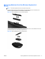
1
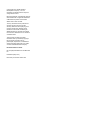
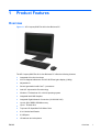
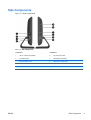
Hardware Reference Guide
HP Compaq 8200 Elite All-in-One Business PC
© Copyright 2011 Hewlett-Packard
Development Company, L.P. The
information contained herein is subject to
change without notice.
Microsoft, Windows, and Windows Vista are
either trademarks or registered trademarks
of Microsoft Corporation in the United
States and/or other countries.
The only warranties for HP products and
services are set forth in the express
warranty statements accompanying such
products and services. Nothing herein
should be construed as constituting an
additional warranty. HP shall not be liable
for technical or editorial errors or omissions
contained herein.
This document contains proprietary
information that is protected by copyright.
No part of this document may be
photocopied, reproduced, or translated to
another language without the prior written
consent of Hewlett-Packard Company.
Hardware Reference Guide
HP Compaq 8200 Elite All-in-One Business
PC
First Edition (May 2011)
Document part number: 656771-001
About This Book
This guide provides basic information for upgrading this computer model.
WARNING! Text set off in this manner indicates that failure to follow directions could result in bodily
harm or loss of life.
CAUTION: Text set off in this manner indicates that failure to follow directions could result in
damage to equipment or loss of information.
NOTE:
ENWW
Text set off in this manner provides important supplemental information.
iii
iv
About This Book
ENWW
Table of contents
1 Product Features ............................................................................................................................................ 1
Overview .............................................................................................................................................. 1
Front Components ................................................................................................................................ 2
Side Components ................................................................................................................................. 3
Rear Components ................................................................................................................................ 4
Keyboard Features ............................................................................................................................... 4
Adjusting Tilt ......................................................................................................................................... 5
2 Hardware Repair and Upgrade ...................................................................................................................... 6
Warnings and Cautions ........................................................................................................................ 6
Additional Information ........................................................................................................................... 6
Connecting Power ................................................................................................................................ 7
Removing and Installing Memory ......................................................................................................... 7
Replacing the Hard Drive ................................................................................................................... 12
Installing a Security Lock .................................................................................................................... 18
Synchronizing the Optional Wireless Keyboard or Mouse ................................................................. 19
Removing Batteries from the Wireless Keyboard or Mouse ............................................................... 21
Appendix A Electrostatic Discharge .............................................................................................................. 22
Preventing Electrostatic Damage ....................................................................................................... 22
Grounding Methods ............................................................................................................................ 22
Appendix B Computer Operating Guidelines, Routine Care and Shipping Preparation .......................... 23
Computer Operating Guidelines and Routine Care ............................................................................ 23
Optical Drive Precautions ................................................................................................................... 24
Shipping Preparation .......................................................................................................................... 24
Index ................................................................................................................................................................... 25
ENWW
v
vi
ENWW
1
Product Features
Overview
Figure 1-1 HP Compaq 8200 Elite All-in-One Business PC
The HP Compaq 8200 Elite All-In One Business PC offers the following features:
ENWW
●
Integrated All-in-One form factor
●
23-inch diagonal widescreen Full HD WLED anti-glare display (1080p)
●
Adjustable tilt
●
Second generation Intel® Core™ i processors
●
Intel Q67 chipset with vPro technology
●
Windows 7 Professional 32- or 64-bit operating system
●
Integrated Intel® HD Graphics
●
Integrated Gigabit Network Connection (10/100/1000 NIC)
●
Up to 8 GB of DDR3 SDRAM memory
●
Up to 1 TB hard drive
●
Tray-load HP SuperMulti DVD Writer Drive
●
6-in-1 Media Card Reader
●
6 USB ports
●
HD webcam and microphone
Overview
1
●
Optional wireless LAN
●
Premium stereo speakers
●
TPM 1.2-compliant embedded security chip
●
Removable panels on the back of the chassis allow users or technicians to easily and efficiently
service the PC
●
Face Recognition for HP ProtectTools software with auto-login capabilities
●
ENERGY STAR® qualified, EPEAT® Silver registered, and offers 89-percent energy-efficient
power
●
Choice of wired or wireless keyboard and mouse
Front Components
Figure 1-2 Front Components
Table 1-1 Front Components
2
Component
Component
1
Webcam
4
Power button and LED
2
Single microphone array
5
High-performance stereo speakers
3
23-inch diagonal 16:9 widescreen LED-backlit full HD
LCD display
Chapter 1 Product Features
ENWW
Side Components
Figure 1-3 Side Components
Table 1-2 Side Components
ENWW
Component
Component
1
HP 6-in-1 Media Card Reader
6
Tray-load optical drive
2
(2) USB 2.0 ports
7
Optical drive eject button
3
Microphone/line in jack
8
Brightness increase button
4
Headphone jack
9
Brightness decrease button
5
Optical drive activity LED
10
Hard drive activity LED
Side Components
3
Rear Components
Figure 1-4 Rear Components
Table 1-3 Rear Components
Component
Component
1
Drive access panel
7
Security lock slot
2
Center access panel
8
Power connector with LED indicator
3
Memory access panel
9
RJ-45 Gigabit Ethernet port
4
Optical drive location
10
Stereo audio line out
5
Hard drive location
11
(4) USB 2.0 ports
6
Memory location
Keyboard Features
Figure 1-5 Keyboard Features
4
Chapter 1 Product Features
ENWW
Table 1-4 Keyboard Features
Component
Component
1
Sleep
5
Fast Forward
2
Fast Reverse
6
Mute Volume
3
Play/Pause
7
Decrease Volume
4
Stop
8
Increase Volume
Adjusting Tilt
Tilt the computer forward up to 5 degrees or backward up to 20 degrees to set it to a comfortable eye
level.
Figure 1-6 Adjusting Tilt
ENWW
Adjusting Tilt
5
2
Hardware Repair and Upgrade
Warnings and Cautions
Before performing upgrades be sure to carefully read all of the applicable instructions, cautions, and
warnings in this guide.
WARNING! To reduce the risk of personal injury from electrical shock, hot surfaces, or fire:
Disconnect the power cord from the wall outlet and allow the internal system components to cool
before touching.
Do not plug telecommunications or telephone connectors into the network interface controller (NIC)
receptacles.
Do not disable the power cord grounding plug. The grounding plug is an important safety feature.
Plug the power cord in a grounded (earthed) outlet that is easily accessible at all times.
For your safety, do not place anything on power cords or cables. Arrange them so that no one may
accidentally step on or trip over them. Do not pull on a cord or cable. When unplugging from the
electrical outlet, grasp the cord by the plug.
To reduce the risk of serious injury, read the Safety & Comfort Guide. It describes proper workstation,
setup, posture, and health and work habits for computer users, and provides important electrical and
mechanical safety information. This guide is located on the Web at http://www.hp.com/ergo.
WARNING! Computers that are inappropriately situated on dressers, bookcases, shelves, desks,
speakers, chests, or carts may fall over and cause personal injury.
Care should be taken to route all cords and cables connected to the computer so that they can not be
pulled, grabbed, or tripped over.
WARNING! Energized and moving parts inside.
Disconnect power to the equipment before removing any access panels.
Replace and secure all access panels before re-energizing the equipment.
CAUTION: Static electricity can damage the electrical components of the computer or optional
equipment. Before beginning these procedures, ensure that you are discharged of static electricity by
briefly touching a grounded metal object. See Electrostatic Discharge on page 22 for more
information.
When the computer is plugged into an AC power source, voltage is always applied to the system
board. You must disconnect the power cord from the power source before opening the computer to
prevent damage to internal components.
Additional Information
For more information on removing and replacing hardware components, the Computer Setup utility,
and troubleshooting, refer to the Maintenance and Service Guide (available in English only) for your
computer model at http://www.hp.com.
6
Chapter 2 Hardware Repair and Upgrade
ENWW
Connecting Power
1.
Plug the power cord into the power connection on the rear of the computer (1).
2.
Plug the three-pronged power plug into the power brick (2) and a power outlet (3).
Figure 2-1 Connecting Power
3.
Plug all peripheral cables into the appropriate ports as needed.
4.
Press the power button on the front of the computer to turn it on.
Removing and Installing Memory
The computer comes with double data rate 3 synchronous dynamic random access memory (DDR3SDRAM) small outline dual inline memory modules (SODIMMs).
The memory sockets on the system board can be populated with up to two industry-standard
SODIMMs. These memory sockets are populated with at least one preinstalled SODIMM. To achieve
the maximum memory support, you can populate the system board with up to 8 GB of memory.
For proper system operation, the SODIMMs must be:
●
industry-standard 204-pin
●
unbuffered non-ECC PC3-10600 DDR3-1333 MHz-compliant
●
1.5 volt DDR3-SDRAM SODIMMs
The DDR3-SDRAM SODIMMs must also:
ENWW
●
support CAS latency 9 DDR3 1333 MHz (9-9-9 timing)
●
contain the mandatory Joint Electronic Device Engineering Council (JEDEC) specification
Connecting Power
7
In addition, the computer supports:
●
512-Mbit, 1-Gbit, and 2-Gbit non-ECC memory technologies
●
single-sided and double-sided SODIMMS
●
SODIMMs constructed with x8 and x16 devices; SODIMMs constructed with x4 SDRAM are not
supported
NOTE:
The system will not operate properly if you install unsupported SODIMMs.
There are two memory sockets on the system board located behind the memory access panel. To
remove or install memory modules:
1.
Remove/disengage any security devices that prohibit opening the computer.
2.
Remove all removable media, such as compact discs or USB flash drives, from the computer.
3.
Turn off the computer properly through the operating system, then turn off any external devices.
4.
Disconnect the power cord from the power outlet and disconnect any external devices.
CAUTION: You must disconnect the power cord and wait approximately 30 seconds for the
power to drain before adding or removing memory modules. Regardless of the power-on state,
voltage is always supplied to the memory modules as long as the computer is plugged into an
active AC outlet. Adding or removing memory modules while voltage is present may cause
irreparable damage to the memory modules or system board.
5.
Place the computer face down on a soft flat surface. HP recommends that you set down a
blanket, towel, or other soft cloth to protect the screen surface from scratches or other damage.
6.
Remove the center access panel by pulling outward on the panel at the slot on the top edge of
the panel.
Figure 2-2 Removing the Center Access Panel
8
Chapter 2 Hardware Repair and Upgrade
ENWW
7.
To remove the memory access panel, pull upward on the two tabs on the inside edge of the
panel (1) and slide the panel off the computer (2).
Figure 2-3 Removing the Memory Access Panel
8.
Pull upward on the two raised tabs on the memory cover and lift the cover off the rear panel.
Figure 2-4 Removing the Memory Cover
ENWW
Removing and Installing Memory
9
9.
To remove a memory module, press outward on the two latches on each side of the SODIMM
(1) then pull the SODIMM out of the socket (2).
Figure 2-5 Removing a Memory Module
10. To install a memory module, slide the SODIMM into the socket at approximately a 30° angle (1)
then press the SODIMM down (2) so that the latches lock it in place.
Figure 2-6 Installing a Memory Module
NOTE: A memory module can be installed in only one way. Match the notch on the module
with the tab on the memory socket.
10
Chapter 2 Hardware Repair and Upgrade
ENWW
11. Press the memory cover back in place. Insert the bottom edge of memory cover into the sheet
metal shielding first then press the top edge of memory cover down. Ensure that all the tabs on
the memory cover are pressed firmly against the sheet metal shielding.
Figure 2-7 Replacing the Memory Cover
12. Place the memory access panel on the rear of the computer so that the edge of the panel is
slightly hanging off the edge of the computer and slide the panel toward the center of the
computer until it snaps in place.
Figure 2-8 Replacing the Memory Access Panel
ENWW
Removing and Installing Memory
11
13. To replace the center access panel, insert the bottom edge of the panel then press down firmly
on each side of the panel working from the bottom to the top so that the panel snaps securely in
place.
Figure 2-9 Replacing the Center Access Panel
14. Lock any security devices that were disengaged when the center access panel was removed.
15. Reconnect the power cord and external devices then turn on the computer. The computer
automatically recognizes the additional memory when you turn on the computer.
Replacing the Hard Drive
The hard drive is located under the drive access panel on the left side of the computer (when viewed
from behind). The drive is secured with one captive screw and is housed in a removable cage.
1.
Remove/disengage any security devices that prohibit opening the computer.
2.
Remove all removable media, such as compact discs or USB flash drives, from the computer.
3.
Turn off the computer properly through the operating system, then turn off any external devices.
4.
Disconnect the power cord from the power outlet and disconnect any external devices.
CAUTION: Regardless of the power-on state, voltage is always present on the system board
as long as the system is plugged into an active AC outlet. You must disconnect the power cord
to avoid damage to the internal components of the computer.
5.
12
Place the computer face down on a soft flat surface. HP recommends that you set down a
blanket, towel, or other soft cloth to protect the screen surface from scratches or other damage.
Chapter 2 Hardware Repair and Upgrade
ENWW
6.
Remove the center access panel by pulling outward on the panel at the slot on the top edge of
the panel.
Figure 2-10 Removing the Center Access Panel
7.
To remove the drive access panel, push downward on the two tabs on the inside edge of the
panel (1) and slide the panel off the computer (2).
Figure 2-11 Removing the Drive Access Panel
ENWW
Replacing the Hard Drive
13
8.
Loosen the captive screw next to the front of the drive that secures the drive to the computer.
You can use either a Torx or slotted screwdriver to loosen the screw.
Figure 2-12 Loosening the Hard Drive Security Screw
9.
Grasp the handle on top of the hard drive cage (1) and slide the cage toward the outer edge of
the computer, then lift the cage out of the computer (2).
Figure 2-13 Removing the Hard Drive Cage
14
Chapter 2 Hardware Repair and Upgrade
ENWW
10. Remove the four mounting screws that secure the drive to the cage. Do not remove the blue
rubber grommets behind each screw. They must stay attached to the cage when installing a new
hard drive.
Figure 2-14 Removing the Hard Drive Mounting Screws
11. Slide the hard drive out of the cage.
Figure 2-15 Removing the Hard Drive from the Cage
ENWW
Replacing the Hard Drive
15
12. Slide the new hard drive into the cage making sure that the connectors on the hard drive are at
the opening of the cage.
Figure 2-16 Sliding the Hard Drive into the Cage
13. Install the four mounting screws that secure the hard drive to the cage. Make sure that the blue
rubber grommets remain attached to the cage behind each screw.
Figure 2-17 Installing the Hard Drive Mounting Screws
16
Chapter 2 Hardware Repair and Upgrade
ENWW
14. Set the hard drive cage down into the bay so that the tabs on the bottom of the cage align with
the slots on the chassis and slide the cage toward the center of the computer (1) so that the
connector on the rear of the drive is securely seated. Rotate the handle on the cage down (2)
and lock it into the clips on top of the cage.
Figure 2-18 Installing the Hard Drive Cage
15. Tighten the captive screw to secure the hard drive cage in place. You can use either a Torx or
slotted screwdriver to tighten the screw.
Figure 2-19 Tightening the Hard Drive Security Screw
ENWW
Replacing the Hard Drive
17
16. Place the drive access panel on the rear of the computer so that the edge of the panel is slightly
hanging off the edge of the computer and slide the panel toward the center of the computer until
it snaps in place.
Figure 2-20 Replacing the Drive Access Panel
17. To replace the center access panel, insert the bottom edge of the panel then press down firmly
on each side of the panel working from the bottom to the top so that the panel snaps securely in
place.
Figure 2-21 Replacing the Center Access Panel
18. Lock any security devices that were disengaged when the center access panel was removed.
19. Reconnect the power cord and external devices then turn on the computer.
Installing a Security Lock
A security lock (sold separately) enables you to secure your computer from theft and unwanted
changes. A security lock is a key lock device that has a wire cable attached. You attach one end of
18
Chapter 2 Hardware Repair and Upgrade
ENWW
the cable to your desk (or other stationary object) and the other to this security slot on the computer.
Secure the security lock with the key.
Figure 2-22 Installing a Security Lock
Synchronizing the Optional Wireless Keyboard or Mouse
The optional wireless keyboard and mouse are easy to set up. Just remove the battery tabs on both
the keyboard and the mouse. Also, make sure the Power switch on the bottom of the mouse is in the
On position (the keyboard does not have a Power switch). Then, turn on the computer. If you have
trouble using the keyboard and mouse, manually synchronize them as described below.
NOTE: For better mouse battery life and performance, avoid using your mouse on a dark or highgloss surface, and turn mouse power off when not in use.
The wireless keyboard and mouse are pre-synchronized to work with your computer. The keyboard
and mouse should work immediately after you first pull the battery tabs to activate the preinstalled
batteries, and then turn on the mouse.
You may need to manually synchronize the wireless keyboard or mouse if they are not functioning.
To synchronize them:
ENWW
1.
Make sure the keyboard and mouse are next to the computer, within 30 cm (1 foot) and away
from interference from other devices.
2.
Turn on the computer.
Synchronizing the Optional Wireless Keyboard or Mouse
19
3.
Insert the wireless receiver into a USB port on the computer.
Figure 2-23 Installing the Wireless Receiver
4.
Make sure the Power switch on the bottom of the mouse is in the On position (1).
5.
Press the Connect button on the bottom of the mouse (2) for fives seconds. The blue activity
LED from the wireless receiver illuminates when the synchronization command has been
received and turns off when synchronization is complete.
6.
Press the Connect button on the bottom of the keyboard (3) for five seconds. The blue activity
LED from the wireless receiver illuminates when the synchronization command has been
received and turns off when synchronization is complete.
Figure 2-24 Synchronizing the Wireless Keyboard and Mouse
NOTE: If the procedure does not work, remove and then re-insert the wireless keyboard and mouse
receiver from the back of the computer and then synchronize the keyboard and mouse again.
20
Chapter 2 Hardware Repair and Upgrade
ENWW
Removing Batteries from the Wireless Keyboard or
Mouse
NOTE:
The wireless keyboard and mouse are optional components.
To remove batteries from the wireless keyboard, remove the battery door on the underside of the
keyboard (1) and lift the batteries out of the battery compartment (2).
Figure 2-25 Removing Batteries from the Wireless Keyboard
To remove batteries from the wireless mouse, remove the battery door on the underside of the mouse
(1) and lift the batteries out of the battery compartment (2).
Figure 2-26 Removing Batteries from the Wireless Mouse
ENWW
Removing Batteries from the Wireless Keyboard or Mouse
21
A
Electrostatic Discharge
A discharge of static electricity from a finger or other conductor may damage system boards or other
static-sensitive devices. This type of damage may reduce the life expectancy of the device.
Preventing Electrostatic Damage
To prevent electrostatic damage, observe the following precautions:
●
Avoid hand contact by transporting and storing products in static-safe containers.
●
Keep electrostatic-sensitive parts in their containers until they arrive at static-free workstations.
●
Place parts on a grounded surface before removing them from their containers.
●
Avoid touching pins, leads, or circuitry.
●
Always be properly grounded when touching a static-sensitive component or assembly.
Grounding Methods
There are several methods for grounding. Use one or more of the following methods when handling
or installing electrostatic-sensitive parts:
●
Use a wrist strap connected by a ground cord to a grounded workstation or computer chassis.
Wrist straps are flexible straps with a minimum of 1 megohm +/- 10 percent resistance in the
ground cords. To provide proper ground, wear the strap snug against the skin.
●
Use heelstraps, toestraps, or bootstraps at standing workstations. Wear the straps on both feet
when standing on conductive floors or dissipating floor mats.
●
Use conductive field service tools.
●
Use a portable field service kit with a folding static-dissipating work mat.
If you do not have any of the suggested equipment for proper grounding, contact an HP authorized
dealer, reseller, or service provider.
NOTE: For more information on static electricity, contact an HP authorized dealer, reseller, or
service provider.
22
Appendix A Electrostatic Discharge
ENWW
B
Computer Operating Guidelines,
Routine Care and Shipping Preparation
Computer Operating Guidelines and Routine Care
Follow these guidelines to properly set up and care for the computer:
ENWW
●
Keep the computer away from excessive moisture, direct sunlight, and extremes of heat and
cold.
●
Operate the computer on a sturdy, level surface. Leave a 10.2-cm (4-inch) clearance on all
vented sides of the computer to permit the required airflow.
●
Never restrict the airflow into the computer by blocking any vents or air intakes.
●
Never operate the computer with any of the access panels removed.
●
Do not place computers so near each other that they are subject to each other’s re-circulated or
preheated air.
●
If the computer is to be operated within a separate enclosure, intake and exhaust ventilation
must be provided on the enclosure, and the same operating guidelines listed above will still
apply.
●
Keep liquids away from the computer and keyboard.
●
Never cover the ventilation slots with any type of material.
●
Install or enable power management functions of the operating system or other software,
including sleep states.
●
When cleaning the computer turn off power to the computer and unplug the power cord before
you do any of the following:
◦
Wipe the exterior of the computer with a soft, damp cloth as needed. Using cleaning
products may discolor or damage the finish.
◦
Do not use cleaners that contain any petroleum based materials such as benzene, thinner,
or any volatile substance to clean the screen or cabinet. These chemicals may damage the
computer.
◦
Wipe the screen with a soft, clean antistatic cloth. For more difficult cleaning situations, use
a 50/50 mix of water and Isopropyl alcohol. Spray the cleaner onto a cloth and use the
damp cloth to gently wipe the screen surface. Never spray the cleaner directly on the
screen surface. It may run behind the bezel and damage the electronics.
◦
Occasionally clean the air vents on all vented sides of the computer. Lint, dust, and other
foreign matter can block the vents and limit the airflow.
Computer Operating Guidelines and Routine Care
23
Optical Drive Precautions
Be sure to observe the following guidelines while operating or cleaning the optical drive.
●
Do not move the drive during operation. This may cause it to malfunction during reading.
●
Avoid exposing the drive to sudden changes in temperature, as condensation may form inside
the unit. If the temperature suddenly changes while the drive is on, wait at least one hour before
you turn off the power. If you operate the unit immediately, it may malfunction while reading.
●
Avoid placing the drive in a location that is subject to high humidity, extreme temperatures,
mechanical vibration, or direct sunlight.
CAUTION: If any object or liquid falls into the drive, immediately unplug the computer and have it
checked by an authorized HP service provider.
Shipping Preparation
Follow these suggestions when preparing to ship the computer:
1.
Back up the hard drive files on PD discs, tape cartridges, CDs, or USB flash drives. Be sure that
the backup media is not exposed to electrical or magnetic impulses while stored or in transit.
NOTE: The hard drive locks automatically when the system power is turned off.
2.
Remove and store all removable media.
3.
Turn off the computer and external devices.
4.
Disconnect the power cord from the electrical outlet, then from the computer.
5.
Disconnect the system components and external devices from their power sources, then from
the computer.
NOTE: Ensure that all boards are seated properly and secured in the board slots before
shipping the computer.
6.
24
Pack the system components and external devices in their original packing boxes or similar
packaging with sufficient packing material to protect them.
Appendix B Computer Operating Guidelines, Routine Care and Shipping Preparation
ENWW
Index
A
additional information
O
optical drive
precautions 24
6
C
components
front 2
rear 4
side 3
computer operating guidelines
P
power
connecting
23
E
electrostatic discharge, preventing
damage 22
F
features
keyboard 4
overview 1
front components 2
H
hard drive
replacing 12
I
installation guidelines 6
installing
hard drive 12
memory 7
security lock 18
7
R
rear components 4
S
security lock location 18
shipping preparation 24
side components 3
specifications
memory 7
synchronizing wireless keyboard
and mouse 19
T
tilt adjustment 5
V
ventilation guidelines 23
W
warnings and cautions 6
K
keyboard
features 4
removing batteries 21
synchronizing wireless 19
M
memory
installing 7
removing 7
specifications 7
mouse
removing batteries 21
synchronizing wireless 19
ENWW
Index
25