1
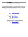
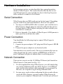
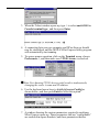
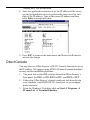
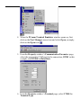
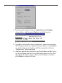
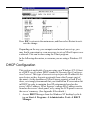
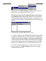
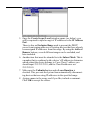
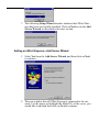
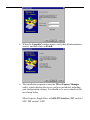
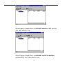
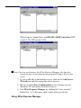
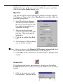
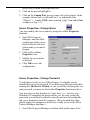
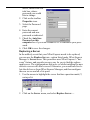
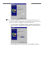
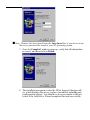
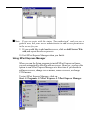
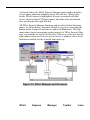
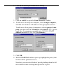
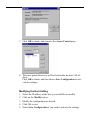
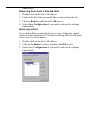
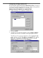
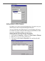
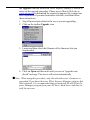
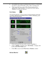
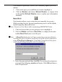
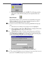
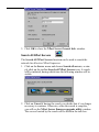
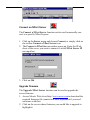
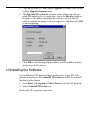
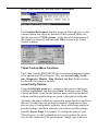
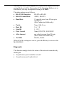
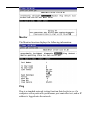
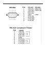
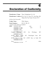
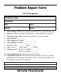
NPort Express User’s Manual First Edition, February 2001 Moxa Technologies Co., Ltd. Tel: +866-2-8919-1230 Fax: +886-2-8919-1231 www.moxa.com [email protected] NPort Express User’s Manual The software described in this manual is furnished under a license agreement and may be used only in accordance with the terms of that agreement. Copyright Notice Copyright 2001 Moxa Technologies Co., Ltd. All rights reserved. Reproduction without permission is prohibited. Trademarks MOXA is a registered trademark of Moxa Technologies Co., Ltd. All other trademarks or registered marks in this manual belong to their respective manufacturers. Disclaimer Information in this document is subject to change without notice and does not represent a commitment on the part of Moxa. Moxa provides this document “as is”, without warranty of any kind, either expressed or implied, including, but not limited to, the particular purpose. Moxa reserves the right to make improvements and/or changes to this manual or the product(s) and/or program(s) described herein at any time. Information provided in this manual is intended to be accurate and reliable. However, Moxa Technologies assumes no responsibility for its use, or for any infringements on the rights of fourth parties which may result from its use. This product could include technical or typographical errors. Changes are periodically made to the information herein; these changes may be incorporated in new editions of the publication. MOXA Internet Services Customer satisfaction is our number one concern. To ensure that customers receive the full benefit of our products, Moxa Internet Services has been set up to provide technical support, driver updates, product information, and user’s manual updates. The following services are provided: E-mail for technical support address: [email protected] FTP site for free driver updates address: or user ID: password: ftp://ftp.moxa.com ftp://ftp.moxa.com.tw ftp your_email_address World Wide Web (WWW) Site for product information address: or http://www.moxa.com http://www.moxa.com.tw 1 Introduction Welcome to Moxa NPort Express, a compact palm-sized communication device that allows you to control serial devices over a TCP/IP based Ethernet. This chapter is an introduction to NPort Express and includes the following sections: q Features q Package Checklist q TCP/IP Description NPort Express provides a data communication solution for connecting Windows and Linux hosts to asynchronous serial devices over a TCP/IP based Ethernet. You may connect your Windows NT/95/98/2000 host to a native RS-232/422/485 serial port, or your PC-based Linux host to a fixed tty port, through a TCP/IP Ethernet. With one asynchronous serial port connection on one end, and a 10/100 Mbps Ethernet connection on the other, NPort Express allows any device that supports primarily the asynchronous communications protocol to attach to a network. NPort Express works like an add-on single-port serial board to your PC server, but with one major advantage— the TCP/IP network. Since the host communicates with the COM port on Nport Express over a TCP/IP network, you are able to control your asynchronous serial device from virtually any location. Although it connects through the virtual link of the Ethernet, the port on NPort Express is recognized as a real COM port by Windows or a fixed tty port by Linux. NPort Express provides both the basic transmit/receive data functions, as well as RTS, CTS, DTR, DSR, and DCD control signals. NPort Express can be used with your existing applications that support serial communication, and comes with a utility program providing a simple step-by-step installation procedure and a maintenance wizard that gives you easy access to your asynchronous device. Features q q q q Compact size—fits in the palm of your hand Auto-detecting 10/100 Mbps Ethernet port 3-in-1 interface supports RS-232/422/485 connections Supports Linux fixed tty drivers q Long range connection through the Internet/Intranet between host and serial port q Supports sharing of the server or ports to multiple hosts q Driver for Windows NT/2000/95/98/ME platforms q Easy configuration and management under Windows NT/2000/95/98/ME q Secured access control to network hosts q Serial connection speed up to 230.4 Kbps Package Checklist q q q q q q One NPort Express NPort Express User's Manual Cross-over 10/100 Mbps Ethernet cable Power Adapter (110V or 230V) Windows NT/2000/95/98/ME device drivers Linux fixed tty device driver TCP/IP Description NPort Express is an Ethernet device that uses IP (Internet Protocol) for communicating over a network. The various protocols supported are ARP, UDP, TCP, ICMP, Telnet/RTelnet, TFTP, and DHCP. Addressing and routing of data blocks over the network are taken care of by IP, whereas TCP (Transmission Control Protocol) helps ensure that data is sent and received error-free. You should be aware of the following basic network terminology before installing and setting up the software for your NPort Express. • Ethernet Address Also referred to as the product’s MAC address, this is a unique 6byte (48-bit) number assigned by the manufacturer. Devices use each other’s MAC address to maintain point-to-point communication over the Internet. • IP Address This is a 4-byte (32-bit) number assigned to a network device for communicating over an Ethernet. Depending on how a device connects to the network (over a LAN, via modem to an ISP’s server, etc.) the IP address may not be fixed. • Port Number A TCP connection or UDP datagram is defined by a destination IP address and port number. It is possible to associate a specific TCP/UDP port number with NPort Express’s serial port. 2 Getting Started Now that you have been introduced to NPort Express's features and specifications, it’s time to install the hardware and get your system up and running. We begin this chapter with a brief explanation of the three general types of operation mode available when using NPort Express. The setup procedure is somewhat different for each operation mode; so first take the time to determine which application best suits your needs. This chapter includes: q Operation Modes • Host-Based Mode • Pair-Connection Mode • Raw-Connection Mode q Hardware Installation • Serial Connection • Power Connection • Network Connection q DIP Switch Settings q IP Address Configuration • Telnet Console • Direct Console • DHCP Configuration Operation Modes NPort Express is an advanced Industrial Serial-to-Ethernet device designed to fit into today's ever-expanding networking world. It extends the usage of traditional COM ports on a PC—an isolated machine with restricted ports—to being able to access ports over a TCP/IP network. Through the nature of networking, you can control your se- rial devices from a distance, either over a LAN, or even over the Internet. In this section, we discuss three types of application—Host-Based Mode, Pair-Connection Mode, and Raw-Connection Mode. Read carefully to determine which application best suits your needs. Host-Based Mode Traditional serial port communication uses a COM port board that slides into one of the slots on the back of your PC. In this case, only the computer containing the board has direct access to the board’s s erial port. With Moxa’s 1-port NPort Express serial device server, communicating with a COM port is much more versatile, since you are now able to access the COM port from a distance, over your company’s LAN, or even over the Internet. Pair-Connection Mode Connecting a serial device to a PC can certainly be accomplished by connecting the serial device directly to one of the PC’s COM ports. This method, however, limits the maximum distance between the PC and serial device to approximately 15 meters. By using two NPort Expresses in tandem, the distance can be extended to half of a kilometer. One NPort Express is connected from its RS-232 port to the COM port of the PC, the serial device is connected to the RS-232 port of the other NPort Express, and then the two NPort Expresses are connected to each other by an Ethernet cable. This mode of operation provides a certain amount of flexibility. The data from the RS-232 port of one NPort Express can be automatically sent to the RS-232 port of the other NPort Express, without the need for an intermediate PC or controller. NPort Express uses its own system software to transport data back and forth between the two devices. Raw-Connection Mode Raw connection mode is used for standard TCP/IP socket programs and provides transparent communication between the network socket program and corresponding asynchronous port. This mode of operation allows the user to easily open the asynchronous serial port and read or write raw data from an Ethernet host to the remote serial device by using an open TCP/IP socket. Hardware Installation In the previous section, we introduced the three general operation modes of NPort Express. This section describes briefly how to connect NPort Express to your serial device, how to hook up the power cable, and how to connect to the Ethernet. Serial Connection NPort Express has one DB9 serial port on the back panel. Depending on your s erial device and serial interfaces, there are two options: 1. You may use a DB9 to DB9 cable to connect your serial device to NPort Express. Simply plug one end of the cable into the port on the back panel of NPort Express and plug the other end into your serial device’s serial port. 2. Refer to Appendix C for details of NPort Express’s DB9 pinouts to make your own serial interface cable. Power Connection You should take the following steps to connect NPort Express’s power adapter. 1. Connect the power adapter’s DC plug into NPort Express’s DC-IN jack. 2. Connect the power adapter to an electrical outlet. Note that there is no on/off switch. The server automatically turns on when plugged into the outlet, and the red PWR light on NPort Express’s top panel will glow to indicate that it is receiving power. Network Connection There are two ways to use the 10/100BaseT Ethernet jack located on NPort Express’s front panel (see Fig. 1-2): 1. For most applications using NPort Express, you will simply plug one end of an Ethernet cable into NPort Express’s 10/100BaseT jack, and the other end into a hub connected to your network. In this case, use a regular straight-through Ethernet cable. 2. In some cases, such as when configuring the drivers and software used with NPort Express, you may connect NPort Express directly to your computer’s Ethernet card. To do this you will need to use a cross-over Ethernet cable, such as the one supplied with your server. The amber Link light will flicker when NPort Express is properly connected to a live Ethernet. DIP Switch Settings The top panel of NPort Express contains a table (shown below) describing DIP switch settings for the serial port. Serial Connection RS-232 ON Console Data OFF Comm. SW1 SW2 SW3 OFF OFF ON ON OFF ON OFF ON Interface Mode RS-232 RS-422 RS-485 by RTS RS-485 ADDC Switch SW1 controls the function of the serial port (ON, or up, for RS-232 Console connection, and down for Data Communication, such as when NPort Express is connected to your serial device). Note that after changing the setting for SW1, you must wait a few seconds for the yellow Ready light to turn off and on, indicating that the function of the serial port has been changed. Switches SW2 and SW3 control the serial port’s Interface Mode. (Note that RTS stands for Ready To Send and ADDC stands for Automatic Data Detection Control.) Keep the following points in mind when setting the DIP switches. • RS-232 Console To use the serial port as a console connection, such as when using the MOXA PComm Terminal Emulator software, set SW1 to ON, SW2 to OFF, and SW3 to OFF. • Telnet Connection Some setup procedures can be carried out through a Telnet connection, during which data is transmitted through NPort Express’s Ethernet port. However, you must set SW1 to OFF to establish a Telnet connection. IP Address Configuration You may choose from two different methods to configure the IP address assigned to your NPort Express. Note that NPort Express is shipped with the IP address set to the following by default: Default IP address: 192.168.127.254 Telnet Console Depending on how your computer and network are configured, you may find it convenient to use network access to set up NPort Express’s IP address. This can be done using the Telnet program. (The figures that follow were generated using a Windows 98 host.) 1. From the Windows 98 desktop click on Start and then select Run. 2. In the Open text input box, type telnet 192.168.127.254 (use the correct IP address if different from the default), and then click OK. 3. When the Telnet window opens up, type 1 to select ansi/vt100 for Console terminal type , and then press Enter. 4. A connection between your computer and NPort Express should now be established, and the MOXA NPort Express utility program will automatically start running. 5. To ensure proper operation, click on the Terminal menu, choose Preferences…, and then make sure VT100 Arrows is checked. .Note: Not choosing VT100 Arrows could result in inadvertently changing the server’s name and IP address. 6. Use the keyboard arrow keys to highlight [serverConfig] as shown below, and then press Enter to select this option. 7. A window showing the various parameters required to configure NPort Express opens up. Those parameters that are “configurable” are enclosed in square brackets, and those parameters that are “display only” are not enclosed. 8. Since our goal in this section is to set the IP address of the server, use the keyboard arrow keys to position the cursor over the first digit of the IP address. Type in the correct IP address and then press Enter to accept this value. 9. Press ESC to return to the main menu, and then select Restart to activate the change. Direct Console You may also use NPort Express’s RS-232 Console function to set up the IP address. We suggest using MOXA PComm Terminal Emulator to carry out the installation procedure. 1. You must first set the DIP switches located on NPort Express’s front panel. Set SW1 to ON, SW2 to OFF, and SW3 to OFF. 2. Either plug NPort Express’s female serial port jack directly into your computer’s male DB9 RS-232 serial port, or use an appropriate converter. 3. From the Windows 98 desktop click on Start à Programs à PComm Lite à Terminal Emulator . 4. When the PComm Terminal Emulator window opens up, first click on the Port Manager menu item and select Open, or simply click on the Open icon . 5. From the Property window’s Communication Parameter page, select the appropriate COM port for the connection, COM1 in this example, and 115200 for Baud Rate. 6. From the Property window’s Terminal page, select VT100 for Terminal Type. 7. Use the keyboard arrow keys to highlight [serverConfig] as shown below, and then press Enter to select this option. 8. A window showing the various parameters required to configure NPort Express opens up. Those parameters that are “configurable” are enclosed in square brackets, and those parameters that are “display only” are not enclosed. 9. Since our goal in this section is to set the IP address of the server, use the keyboard arrow keys to position the cursor over the first digit of the IP address. Type in the correct IP address and then press Enter to accept this value. Press ESC to return to the main menu, and then select Restart to activate the change. Depending on the way your computer and network are set up, you may find it convenient or even necessary to set up NPort Express over a network. This can be done using the Telnet program. In the following discussion, we assume you are using a Windows NT host. DHCP Configuration This section is applicable if you are using your Windows NT 4.0 host as a DHCP server, where DHCP stands for Dynamic Host Configuration Protocol. This type of server is set up to provide IP addresses for new devices as they log onto a network (hence the Dynamic part of the name). As the operation of NPort Express requires a fixed IP address, we strongly recommend that you establish an IP reservation list in DHCP in order to maintain fixed IP assignments based on the server’s MAC address. NPort Express’s unique MAC address can be found on the server’s back panel, or by using the LCD panel to access the server’s memory. (See Appendix B for details.) 1. Access DHCP Manager from the Windows NT desktop by clic king on Start à Programs à Administrative Tools à DHCP Manager. 2. The left side of the DHCP Manager window will show a list of DHCP hosts currently hooked up to the network. Note that before you can make changes to the host’s parameters, there must be a minus sign (-) located to the left of the server name (Local Machine in the example shown below.) If, as shown below, there is a plus sign (+) to the left of the server name, use the left mouse button to click on the name until you see the minus sign appear. 3. You must now define the DHCP server “scope”. A “scope” is simply a range of IP addresses that the server assigns to machines as they log onto the network. Since the assignment is dynamic, the IP address assigned to a particular device can change each time the device logs in. What we will do is use DHCP Manager to set aside a specific IP address that will always be assigned to your NPort Express when it is hooked up to the network. When the device is not hooked up, the reserved IP address is not used. If you have already defined a scope, continue with step 6 below. 4. To get started, click on DHCP Options and then chose Scope from the pull down menu. 5. Once the Create Scope (Local) window opens (see below), you will be required to input a range of IP addresses in the IP Address Pool . There is also an Exclusion Range used to prevent the DHCP server from issuing addresses to existing devices that have already been assigned IP addresses from this range. By using the Add and Remove buttons, several different ranges can be excluded, and later included. 6. Another item that must be attended to is the Subnet Mask. This is a number that is combined with a device’s IP address to determine which subnet the device belongs to. For a Class C address you should input 255.255.255.0, and for Class B addresses use 255.255.0.0. 7. Make sure the Unlimited option under Lease Duration is checked. This prevents the system from automatically disconnecting devices that are using IP addresses in the specified range. 8. Assign a name to the scope, and if you like, include a comment. Click OK to accept the values. 9. A window opens with the question: Activate the new scope now? Click on Yes to activate. At this point we explain how to input a unique IP address reserved exclusively for use by your NPort Express. 10. From the DHCP Manager – (Local) menu bar, click on Scope , and then select Add Reservations. 11. The Client Properties window that opens contains text input boxes for IP Address, Unique Identifier, Client Name, and Client Comment. First, enter the selected IP address, and then locate and enter your NPort Express’s MAC address in the Unique Identifier field. (The MAC address is located on NPort Express’s back panel, or see Appendix B for an explanation of using NPort Express’s LCD buttons to locate the MAC address.) Be sure to enter the same Client Name that was entered in the Name field of the Create Scope - (Local) window (see step 8 above). The Client Comment is optional. At this point you should double-check the MAC address and IP address, and then click OK to accept the values. 12. To check that the numbers just entered are correct, return to the DHCP Manager main window, click on Scope, and then choose Active Leases from the pull down menu. The IP address reserved for your NPort Server light will be displayed in the window that opens up. Check to make sure that it is accurate. 3 Installation and Configur a tion In the previous chapter we explained how to set up NPort Express for use on a network. In this chapter we explain how to configure the server for the particular application you have chosen. We discuss the following topics: q Host Based Mode • Single Host Mode Ø Driver and Software Installation Ø Adding an NPort Express—Add Server Wizard Ø Using Express Manager Ø NPort Express Manager Toolbar Icons • Custom Mode Ø Driver and Software Installation Ø Adding an NPort Express—Add Server Wizard Ø Using NPort Express Manager Ø NPort Express Manager Toolbar Icons Ø Granting Access to Hosts Ø Adding Routes to NPort Express Ø Examples of Internet/Intranet Routing Configuration • Upgrading NPort Express Firmware q Pair-Connection Mode q NPort Server Diagnostic • Configuration • Viewer Status and Diagnose q NPort Server Monitor • Configuring NPort Server Monitor • Save and Load Configuration • Monitor Ø Port Status Ø Refresh Monitor Ø Reset Port Ø Reset Server • Upgrading NPort Server Firmware Host-Based Mode There are two options under Host-Based Mode. Follow the installation instructions under Single Host Mode if you will be accessing NPort Express from just one host. Follow the instructions under Custom Mode for all other Host-Based applications. Single Host Mode Driver and Software Installation 1. Insert the NPort Express disk into either the floppy disk drive or CD ROM drive, depending on the type of disk that was provided. From the Start Menu, choose Run. 2. Type X:\setup in the dialog box, in which X is the appropriate drive letter. 3. The Welcome to NPort Express window opens. Click on Next to continue with the installation. 4. Select the type of application, Single-Host in this case, and then click on Next. 5. In the Select Destination Directory window, click on Next to install NPort Express files in the given default directory, or use the Browse button to enter the name of a different directory. 6. The Installing window opens to indicate that files are being copied to the appropriate folder. 7. The following Setup Wizard window indicates that NPort Manager has been successfully installed. Click on Next to run the Add Server Wizard, as described in the next section. Adding an NPort Express—Add Server Wizard 1. Select Yes from the Add Server Wizard, and then click on Next to continue. 2. The next window lists all NPort Expresses connected to the network. Use the mouse to highlight the Model No. of the server you would like to add and then click on Next to continue. (If you forgot to plug in the your server’s power cord, do so now and then click on Find… to locate the server.) 3. You must choose a COM port number to assign to your NPort Express serial port. Highlight the desired number from the pull down list and then click on Next to continue. 4. Choose and then type a password in both the Server Password and Confirm Password text input boxes, and then click on Next to continue. Check the Auto-Saved box if you would like the password to be saved on your computer. 5. When the Complete! window opens, verify that all information is correct, and then click on Finish. 6. The installation program evokes the NPort Express Manager utility, which displays the server you have just added, including port configuration settings. You should see a screen similar to the one shown below. NPort Express, Single-Host, with RS-232 interface (DIP switch 2 OFF, DIP switch 3 OFF). NPort Express, Single-Host, with RS-422 interface (DIP switch 2 OFF, DIP switch 3 ON). NPort Express, Single-Host, with RS-485 (by RTS) interface (DIP switch 2 ON, DIP switch 3 OFF). NPort Express, Single-Host, with RS-485 (ADDC) interface (DIP switch 2 ON, DIP switch 3 ON). .Note: Forshows easy verification, the NPort Express Manager title bar also the type of installation just performed (Single-Host in this case). 7. If you would like to add another server, click on the Add Server Wizard icon and then repeat the above process. 8. Be sure to select Save Configuration to save settings to your Windows NT host and to the selected server. 9. Exit NPort Express Manager by clicking the “close window” button (the “x” in the upper right corner) when you fin ish. Using NPort Express Manager When you run the Setup program to install NPort Express software, you are automatically asked to add one server. However, you have the option to run NPort Express Manager at a later time if you decide to add more servers, change server names, remove servers, or change COM names. To start NPort Express Manager, click on: Start à Programs à NPort Express à NPort Express Manager. As shown below, the NPort Express Manager main window displays server names and model numbers in the left info box. When a particular NPort Express is highlighted, the port associated with that server, the associated COM port names, and other relevant information, appear in the right info box. All NPort Express Manager functions can be selected from the main menu. Functions related to servers are put under the Server menu, and port functions are under the Port menu. The help menu shows topics concerning various aspects of NPort Express Manager’s operations, as well as on-line help. Moreover, when you use the right mouse button to click on a port or server, a window with a list of functions available for the selected item opens up. Figure 3-1. NPort Express Manager main window, Single-Host mode NPort Express Manager Toolbar Icons The NPort Express Manager toolbar icons also provide an easy way for you to manage your servers. Save all Server Modifications of NPort Express or changes to port configurations must be saved by the OS and the server in order to be activated. Clicking on the toolbar Save all Servers icon will automatically detect any changes and save them in the appropriate places. Add Server If you need to add another NPort Express to your system after the in itial installation, simply click on the toolbar Add Server icon to start the Add Server Wizard, and then follow the instructions given earlier for adding new servers. Restart the system as requested. Delete Server If one of the NPort Expresses originally installed on your system has been moved, or you do not need the server installed on your system anymore, then you can use NPort Express Manager to delete it. First highlight the name of the server you would like to remove, and then click on the toolbar Delete Server icon. Map Port You may use NPort Express Manager to change previously assigned COM names. Click on the toolbar Map Port icon, and then follow the procedure given below: 1. Start NPort Express Manager, and then click on the name of the server, listed in the left info box, whose port number you would like to change. 2. The port on this particular server will be listed in the right info box. Click on the port to highlight it. 3. Click on the toolbar Map Port icon. 4. Select the new COM port name you would like to map to. .Note:boxIt does not matter if the Mapping COM number consecutively check is checked or unchecked since there is only one port. 5. Click OK to finish, and return to the NPort Express Manager main window. Unmap Port If you do not need to use a port any more, you may use the toolbar Unmap Port function to remove it from your Windows NT operating system. 1. Click on the server you would like to modify. The port on that server will be listed in the right info box. 2. Click on the port to highlight it. 3. Click on the Unmap Port icon to remove the selected port. In the example shown here, we deleted Port 1, as indicated by the “ellipses” (…) under COM, and a missing “plug” icon under Port (compare to Fig. 3-1). Server Properties—Change Name You may modify the server name by using the toolbar Properties function. 1. Start NPort Express Manager, and then click on the name of the server, listed in the left info box, whose name you want to change. 2. Click on the toolbar Properties icon. 3. Modify the server name as desired. 4. Click OK to save the configuration. Server Properties—Change Password To add more security to your NPort Express, it is highly recommended that you set a password. If you did not set the password while running the Add Server Wizard, or you would like to change the current password, you may use the toolbar Properties function to do so. You may also use this function to “Auto-Save”, i.e., to have your Windows OS remember the password for you. By auto saving the password, you will not be asked to enter the password when modifying server properties from this computer. (Keep in mind that other people using your computer will also have ready access to the NPort Express Manager functions.) 1. Start NPort Express Manager, and then click on the name of the server, listed in the left info box, whose password you would like to change. 2. Click on the toolbar Properties icon. 3. Select the Password page. 4. Enter the current password and new password as indicated. 5. Check the Auto Save Password on this computer box if you want Windows NT to remember your password. 6. Click OK to save the changes. Replacing a Server In the unlikely event that your NPort Express needs to be replaced, you can use the Replace Server… option listed under NPort Express Manager’s Server menu. This procedure uses NPort Express’s “hotswap” feature, and provides an easy way for you to find the replacement server. The configurations that were set while installing the now defective server will also be saved. Otherwise, you would need to delete the old server from NPort Express Manager, and then configure the new server and all of its ports. 1. Use the mouse to highlight the server that has a question mark (?) on top of it. 2. Click on the Server menu, and select Replace Server…. 3. The Replace Server window that opens up shows a list of servers that have not been configured. The new server can be identified by looking at the serial number. 4. Use the pop up window to confirm the Server. 5. If the new server is password protected, enter the pre-set password when prompted to do so. 6. Click OK to save the current settings to the new server. 7. Click on Save Configuration to activate. .Note:arePrevious configurations, including server name and port settings, retained after going through the above described Replace Server procedure. However, the server password will be set to the one you entered during the replacement procedure, so you will need to start using the new password to access the server. Custom Mode Driver and Software Installation 1. Insert the NPort Server Express disk into either the floppy disk drive or CD ROM drive, depending on the type of disk that was provided. From the Start Menu, choose Run. 2. Type A:\setup in the dialog box if using drive A, and then click OK. (Replace A with the correct drive letter if you are using a different drive.) 3. The setup program prompts you with a welcome message and asks if you want to install NPort Express now. Click on Next. 4. Select the type of application, Custom in this case, and then click on Next. 5. In the Select Destination Directory window that opens up, click on Next to install NPort Express files in the given default direc- tory, or click on Browse, enter the name of a different directory, and then click on Next. 6. A window opens up asking if you would like to run Add Server Wizard now. Follow the instructions, select Yes, and then click on Next. 7. Click Next to start Add Server Wizard. Continue with the instructions in the next section. Adding an NPort Express—Add Server Wizard 1. In the Add Server Wizard window, use the mouse to highlight the server you want to add. Note that Select Existing NPort Servers on the network should be selected. If you forgot to plug in the power cord for your system, do so now and then click on Find… . 2. If the server is at a remote site, you must select Manually Enter the IP address of NPort Server and then click on Next. Enter the server’s IP address in the text input box, and then click on Next to continue. 3. First-time installers jump directly to next step. If the server being set has a password, you will see a password protected screen. If you are the server administrator, select Yes and enter the password. However if you’re NOT the administrator, select No and continue to install ports. .Note:addIf you’re not the administrator, be sure to ask the administrator to you to the access control list of the server. 4. Confirm that the displayed IP address is correct, or key in a dedicated IP address assigned by your LAN administrator. .Note:sultIf with you have a DHCP server on your local network, be sure to conthe DHCP administrator to assign dedicated IP addresses to the server, and to the computers connected to the server. 5. You must choose a COM port number to assign to your NPort Express serial port. Highlight the desired number from the pull down list. 6. Choose and then type in a password. Click on Next to continue. .Note:theRemove the check mark from the Auto-Saved box if you do not want server password be saved to your NT operating system. 7. Once the Complete! window opens up, verify that all information is correct, and then click on Finish. 8. The installation program evokes the NPort Express Manager utility, which displays the server you have just added, including port configuration settings. You should see a screen similar to the one below if the Add Server Wizard completed the task successfully. .Note:general If you see ports with the status ‘Non-authorized’, and you are a user, ask your server administrator to add access permission to the server for you. 9. If you would like to add another server, click on Add Server Wizard, and repeat the above process. 10. Exit NPort Express Manager when you finish. Using NPort Express Manager When you run the Setup program to install NPort Express software, you are automatically asked to add one server. However, you have the option to run NPort Express Manager at a later time if you decide to add more servers, change server names, remove servers, or change COM names. To start NPort Express Manager, click on: Start à Programs à NPort Express à NPort Express Manager. As shown below, the NPort Express Manager main window displays server names and model numbers in the left info box. When a particular NPort Express is highlighted, the port associated with that server, the associated COM port names, and other relevant information, are shown in the right info box. All NPort Express Manager functions can be selected from the main menu. As shown below, functions related to servers are put under the Server menu, and port functions are under the Port menu. The help menu shows topics concerning various aspects of NPort Express Manager’s operations, as well as on-line help. Moreover, when you use the right mouse button to click on a port or server, a window with a list of functions available for the selected item opens up. Figure 4-2. NPort Manager and the menus NPort Express Manager Toolbar Icons The NPort Express Manager toolbar icons also provide an easy way for you to manage your servers. Save all Servers In order to be activated, modifications of NPort Express, or changes to port configurations, must be saved by the NT system or the server. Clicking on the toolbar Save all Servers icon will automatically detect any changes and save them in the appropriate places. Add Server If you need to add another NPort Express to your system after the in itial installation, simply click on the toolbar Add Server icon to start the Add Server Wizard, and then follow the instructions given earlier for adding new servers. Restart the system as requested. Delete Server If one of the NPort Expresses originally installed on your system has been moved, or you do not need the server installed on your system anymore, then you can use NPort Express Manager to delete it. First highlight the name of the server you would like to remove, and then click on the toolbar Delete Server icon. Map Port You may use NPort Express Manager to change previously assigned COM names. Click on the Map Port toolbar, and then take the following steps: 1. Start NPort Express Manager, and then click on the name of the server, listed in the left info box, whose port number you would like to change. 2. The port on this particular server will be listed in the right info box. Click on the port to highlight it. toolbar Map Port icon. 3. Click on the 4. Select the new COM port name you would like to map to. .Note: It does not matter if the Mapping COM number consecutivelycheck box is checked or unchecked. 5. Click OK to finish. Unmap Port If you do not need to use a port any more, you may use the toolbar Unmap Port to remove it from your Windows NT operating system. 1. Click on the server you would like to modify. The port on that server will be listed in the right info box. 2. Click on the port to highlight it. 3. Click on the Unmap Port icon to remove the selected port. In the example shown here, we deleted Port 1, as indicated by the “ellipses” (…) under COM, and a missing “plug” icon under Port. Server Properties—Change Name You can modify the server name by using the toolbar Properties function. 1. Click on the server whose name you want to change. 2. Click on the toolbar Properties icon. 3. Modify the server name as desired. 4. Click OK to save the configuration. Server Properties—Change Password To add more security to your NPort Express, it is highly recommended that you set a password as soon as you complete the installation. If you did not set the password while running Add Server Wizard, or you would like to change the current password, you may use the toolbar Properties function to do so. You may also use this function to “Auto-Save”, i.e., to have Windows NT remember your password for you. By auto saving the password, you will not be asked to enter the password when modifying server properties from this computer. (Keep in mind that other people using your computer will also have ready access to the NPort Express Manager functions.) 1. Click on the server whose password you would like to change. 2. Click on the toolbar Properties icon. 3. Select the Password page. 4. Enter the current password and new password as indicated. 5. Check the Auto Save Password on this computer box if you want Windows NT to remember your password. 6. Click OK to save the changes. Granting Access to Hosts It is possible to assign access permission to hosts to allow them access to the ports on a shared NPort Express. For security reasons, the access control list can only be defined by the server’s administrator. If you have not been granted access, you will see a screen with the message ‘Non-authorized’ for the ports. After running Add Server Wizard and typing in your password showing that you are the administrator, you are granted access to the server you have added. You may go to server properties to check that. How- ever, if you did not enter the correct password, you can still map the ports to your NT, but you will not have access to the ports. You will need to ask your administrator to add your IP address to the access control list of the server to grant you access. If you are not sure of the IP address of the host you want to add, run “ipconfig” from the host’s NT MS-DOS prompt. .Note:empty If you want to allow the ports to be accessed by all users, simply the access control list. To grant access, you must first enter the Access Control Page: 1. Run NPort Express Manager. 2. Click on the server you want to modify. 3. Click on the toolbar Server Properties icon. 4. Select the Access Control tab. 5. The screen will show a list of ports, and two methods of adding permission. When adding access permission, you may either view the access control list by Port, or by IP address. These two approaches also apply to the procedure for adding new hosts. The next two sections describe how to add hosts using both approaches. Configuring Through View by IP Address Using the view access control list by IP address option displays the access control list by giving the server IP addresses. It is clear to see which IP addresses have been granted access to which ports, and which IP addresses are allowed onto the server. Adding Access Permission to One Host If a particular host is permitted access to all ports on a specific server, we recommend that you configure using the view access control list by IP address option. 1. Click on the Access Control tab, and then select the IP address option next to View access control list by: 2. Click on the server you would like to modify. 3. Click on Add IP to open the Grant Access IP window. 4. To add access for only one computer, select a single computer, and then enter the host’s IP address in the appropriate text box. To add access for a group of computers, select a group of computer, and then enter the IP address and netmask. (E.g., for network class C computers, you might enter 192.168.1.0 for IP address and then 255.255.255.0 for netmask.) 5. Click OK. 6. When the Add Port window opens up, highlight the port(s) that the host will be granted access to. Note that you can select blocks of ports by holding down the left mouse button while scrolling through the list of ports. 7. Click OK to finish, and return to the Access Control page. 8. The ports granted access to will be listed under the host’s IP address. Click OK to finish, and then choose Save Configuration to activate the settings. Modifying the Host Setting 1. Select the IP address of the host you would like to modify. 2. Click on the Modify button. 3. Modify the configuration as desired. 4. Click OK to exit. 5. Select Save Configuration if you need to activate the settings immediately. Removing Ports from a Granted Host 1. Double click on the host’s IP address. 2. Click on the Port that you would like to remove from the list. 3. Click on Remove, and then click OK to exit. 4. Select Save Configuration if you need to activate the settings immediately. Removing a Host If you do not allow a particular host to use any of the ports, simply remove the host from the list. Note that removing all hosts will grant server access to all computers. 1. Double click on the host’s IP address. 2. Click on the Remove button, and then click OK to exit. 3. Select Save Configuration if you need to activate the settings immediately. Configuring Through View by Port By choosing the option View access control list by Port, it is easy to see the access permission granted for each port. This viewing option is particularly useful for adding hosts to specific ports. Adding a Host IP Address to a Specific Port 1. Click on the Port you would like to add the host to. 2. Click on Add IP. 3. To add access for only one computer, select a single computer, and then enter the host’s IP address in the appropriate text box. To add access for a group of computers, select a group of computer, and then enter the IP address and netmask. (E.g., for network class C computers, you might enter 192.168.1.0 for IP address, and then 255.255.255.0 for netmask.) 4. Click OK to finish. 5. When the Server Properties window opens up, you can look at the Access Control page to verify that the host was added to the port. 6. Click OK to finish. 7. Select Save Configuration if you need to activate the settings immediately. Modifying Granted Host 1. Click on the port. 2. Click on the IP address you want to change, and then click on Modify. 3. Modify the IP address as needed. 4. Select Save Configuration if you need to activate the settings immediately. .Note:thisThisport.host modification will only be activated for the specific host of Removing Granted Host 1. Click on the port. 2. Click on the IP address of the host to be removed, and then click on Remove. 3. Click OK to finish. 4. Select Save Configuration if you need to activate the settings immediately. Adding Routes to NPort Express To enable access from an Internet/Intranet host, first make sure your NPort Express can be connected through the Internet. You may add routes into NPort Express if your Windows NT host is at a remote site. This section lists the steps you should follow to add new routes, including examples you can refer to. Adding Routes Through Server Properties 1. Select Start à Programs à NPort à NPort Express Manager. 2. Select the server you want to add routes to. 3. Click on the toolbar Server Properties icon, and then the Advanced tab. 4. 5. 6. 7. 8. Click on Add. Enter the Destination, Gateway, Netmask and Metric as needed. Click OK to exit Gateway Settings. Click OK to exit Server Properties. Save Configuration as needed. Modifying Routes 1. Start NPort Manager. 2. Select the server whose routes you want to modify. 3. Select Server Properties from the toolbar, or double click on the server. 4. Click on the Advanced tab. 5. Select the route settings you want to change, and then click on Modify. 6. Click OK to exit Gateway Settings. 7. Save Configuration as needed. Removing Routes 1. Start NPort Express Manager. 2. Select the server whose routes you want to remove. 3. Select Server Properties from the toolbar or double click on the server. 4. Click on the Advanced tab. 5. Select the route setting you would like to remove, and then click on Remove. 6. Click OK to exit Gateway Settings. 7. Save Configuration as needed. Examples of Internet/Intranet Routing Configuration Configuring Router for Internet Connection Some routers have the capability to learn routes automatically. To ensure that your Internet connection will work properly, you can consider adding the routes for those routers without RIP protocol. Figure 5-1 shows you an example of connecting to the Internet through a Router. 203.67.6.10 NT Router 203.67.6.254 TCP/IP NPort Server NPort Lite 203.67.6.253 Serve r Internet Figure 4-3. Scheme for LAN with NPort Express connecting to the Internet. Your route will be: Asynchronous Devices Configuring Routers for one Internet Connection and one Intranet Connection You will need to add two routes to NPort Express for the more complex case in which the server is connected to the Internet and Intranet at the same time. Asynchronous Devices 203.67.6.10 NT Router 203.67.6.254 Router 203.67.6.252 Router 202.65.6 TCP/IP 203.67.6.253 NPort Internet NPort NPort Server Lite Server Serv er Figure 4-4. Scheme for NPort Express connecting to the Intranet or Internet. 21 50 6 32 4 N T R .0 7e 3 .rC o u P tP I/ You will only need to add the first route to NPort Express if the environment is the same as above, except that the server only needs to be accessed by the private network. Configuring Routes through Multiple Routers You should configure NPort Express as follows for the case in which the two subnets reach through the routers. 203.67.6.10 Router 203.67.6.254 NT Router 203.67.6.252 TCP/IP Router 203.67.6.253 N P o r t Router Server NPort Sever Lite NPort Server Figure 4-5. Scheme for NPort Express connecting to multiple routers. 204.5.6.2 Asynchronous Devices 202.65.66.4 202.65.66.5 If only the 202.65.66.0 network is needed to provide access, configure your NPort Express as shown below. Upgrading NPort Express Firmware Upgrade Moxa continually upgrades its driver software and server firmware to keep pace with the ever-expanding world of computing. You can use the Upgrade function located on NPort Express Manager’s toolbar to carry out the upgrade procedure. Please access Moxa's Web site at www.moxa.com to download the required computer file (contact our sales department if you need assistance with this), and then follow these instructions. 1. Stop all port action related to the server you are upgrading. 2. Click on the toolbar Upgrade icon. 3. Locate and then select the filename of the firmware that you downloaded. 4. Click on Open and then wait until you see an “upgrade completed” message. The server will restart automatically. .Note: When using this procedure, only the selected server’s firmware is upgraded. If you know that new NPort Express Manager software has been released, it is recommended that you uninstall the old NPort Express Manager program from your NT host’s hard drive, and then install the new one. 4 Utilities In the previous chapter we explained how to set up NPort Express for use on a network. In this chapter we explain how to configure the server for the particular application you have chosen. We discuss the following topics: q NPort Server Diagnostic • Configuration • Viewer Status and Diagnose q NPort Server Monitor • Configuring NPort Server Monitor • Save and Load Configuration • Monitor q Upgrading NPort Server Firmware NPort Server Diagnostic NPort Server Diagnostic is one of the NPort Express utilities installed along with the driver. NPort Server Diagnostic provides remote self-test functions for NPort Express. It can perform an internal loopback test and external loopback test. In general, you may run Diagnostic to perform internal loopback tests to make sure NPort Express is working properly. The test results can be saved as a text file for a maintenance record, indicating the test date, time, and results. You should refer to Chapter 3 for instructions on how to install the driver. In this section we explain how to configure and use Nport Server Diagnostic. To start NPort Server Diagnostic, click on Start à Programs à NPort Express à NPort Diagnostic. This will open the NPort Server Diagnostics window, from which you can navigate to the different functions provided by this utility. Configuration The first time you run NPort Server Diagnostics, you will need to choose configuration settings by selecting target servers, ports, and diagnostics items. 5. To start the configuration procedure, either click on Diagnose and then choose Config, or just click on the toolbar Config icon. 6. The Diagnostic Config window will open, displaying the tabs Test Object, Test Item, and Communication Parameters. We start with the Test Item tab, which is chosen automatically when the window opens. 7. When the Diagnostic Config window first opens, the Selected NPort Server info box under the Test Object tab is empty. Click on the text box’s pull down button and choose the desired server. If the server you’re looking for is not on the list, click on Search to let the program search the network for all connected NPort Expresses, and then choose the desired server. 8. Press Enter to select. 9. If the NPort Express you chose is password protected, the following window will open. Type in the correct password and then click OK. 10. The server information will now appear in the Selected NPort Server info box. .Note: ClickyoutheaddSearch button before selecting a server from the pull down list if more NPort Expresses after the Diagnostics utility is initiated. Otherwise the new server will not be listed in the pull down list. 11. The check box for ports needing to be tested should be checked (refer to the figure in step 6). For those ports that no longer need to be tested, click inside the checked box to remove the check mark. 12. If you do not need to change any Test Items or Communication Parameters, click OK to return to the NPort Server Diagnostics window. Otherwise continue the configuration process in the next subsections. Test Item Selection Click the Test Item tab in the Diagnostic Config window. The tests that you want to run should be checked. Add or remove check marks as necessary by clicking inside the appropriate check box. ¨ ¨ Internal Test: If this test item is selected an internal test will be done on the RS-232 serial port, and the result (successful or failed) will be displayed when the test is completed. External Test: If this test item is selected, an external test will be done to check that the connection signals for each port are working properly. For the external test, you will need to connect each port to a loopback tester. Refer to Appendix C for the specifications. If you are using Model DE-331, the external loopback test only applies to the RS-422 mode. The items DTRà à DSR and DTRà à DCD are not supported. The items described below which are check marked will be tested. ¨ Tx ν Rx: Displays the test result of tranmitting and receiving data between two ports. ¨ RTS γ CTS: Displays the test result of the RTS and CTS signals between two ports. ¨ DTR γ DSR: Displays the test result of the DTR and DSR ¨ signal between two ports. DTR γ DCD: Displays the test result of the DTR and DCD signal between two ports. Communication Parameters Selection Click on the Communication Parameters tab to set up communication parameters. Set Baud rate, Data bits, Parity, and Stop bits, to the appropriate values. Last Step 13. Click OK in the bottom right corner of the Diagnostic Config window to return to the NPort Server Diagnostics window. All NPort Expresses that are to be tested will be listed in the left info box as shown below. Viewer Status and Diagnose Before starting the testing procedure, you can check the status of your NPort Express. 1. Either click on the Diagnose menu and then choose Server Status, or click on the toolbar Server Status icon to open the NPort Server Status window. The server information displayed is: server name, IP address, model number, serial number, and firmware version. The port information displayed is the COM name (COM3 in the example below), serial port interface, and current port status. 2. Click OK to return to the NPort Server Diagnostics window. 3. To begin testing, either click on the Diagnose menu and then choose Go, or simply click on the toolbar Go icon. . 4. A window containing a warning message opens up. Click OK to proceed with the testing. 5. The Test Status window that opens displays some basic information about the test and test results. Click on View Report to see details about the tests that were done. 6. The report will be displayed in the Test Report info box. Items that tested okay will be marked with a green OK. Error codes are in red. To check error messages with corresponding error codes, choose Error Code Reference under the Help menu in the NPort Server Diagnostics window. If one or more of the test items for a particular server fails, the test object in the To be tested… info box is marked with a red colored Fail. Printing The printing function is included to provide an easy way to print out test reports. 7. Click on the NPort Express shown in the To be tested… info box to determine which testing report to print. 8. Click on File and then choose Print… or simply click on the toolbar printer icon to print out the report. Save This function allows you to save the diagnostic report in a “txt” file for future reference. 1. Click on the test object in the To be tested… info box. 2. Click on File and select Save Report, or click on the toolbar Save Report icon to save the report. 3. You will be prompted to enter a file name in the File name text input box. Click on Save to save the file to disk. Exiting the Program When you have finished all testing and report procedures, click on File and choose Exit, or click the close window button in the upper right hand corner of the NPort Server Diagnostics window. NPort Server Monitor NPort Monitor is one of the NPort Express utilities installed along with the driver. You should refer to Chapter 3 for instructions on how to install the driver. NPort Server Monitor provides a remote port monitoring function for NPort Express. It allows you to obtain useful information about the server, such as Login Name, Login IP Address, DTR, RTS, Tx/Rx Count, and throughput. In this section we explain how to configure and use Nport Monitor. To start NPort Monitor, click on Start à Programs à NPort Express à NPort Monitor . This will open the NPort Server Monitor window, shown below. Configuring NPort Server Monitor The first time you run NPort Monitor you will need to set up the configuration by selecting target servers, target ports, and monitoring items. You will be able to save the configuration for the next time you use it, or go back to NPort Server Monitor to check the monitoring information. Check the Help menu if you have trouble using this program. 1. Click on the Monitor menu and select Configure, or click on the toolbar Configure icon to open the Monitor configuration window. Note the three tabs, Select Port, Select Item, and General, located towards the top of the window. The Select Port tab will be selected by default, and the program will find all NPort Expresses currently connected to the network. 2. From the Server IP Address pull down menu, select the server(s) that you want to monitor. The server information will appear in the Monitoring NPort Server info box. .Note: Click the Search button before selecting a server from the pull down list if you add more NPort Expresses after the Diagnostics utility is initiated. Otherwise the new server will not be listed in the pull down list. 3. The check box for all ports needing to be monitored should be checked (refer to the figure in step 2). For those ports that no longer need monitoring, click inside the checked box to remove the check mark. 4. If you need to delete some servers from the list, highlight the servers to be deleted, and then click on the Delete Server button in the lower left hand corner of the Monitor configuration window. 5. Click on the Select Item tab to open the list of options shown below. This function is provided so that you can select monitoring items according to your need. Items selected will be displayed in the NPort Server Monitor screen. Check or uncheck the boxes as needed. 6. Click the General tab to set up the Sampling interval. Sampling time is the time interval for updating the current data of NPort Express, where the time interval ranges from 1 to 20 seconds. Select a number from the pull-down list to set up the time, and then click OK. 7. After returning to the NPort Server Monitor window, the servers and ports that were selected will be listed in the info box. General information such as Model No., NPort Server Name, OP_mode, NPort Server IP Address, and Port No. will also be displayed. Save and Load Configuration Save Configuration This function is provided so that you can save new or updated configurations for future use. After initiating NPort Monitor, you may choose to either load a saved configuration file, or configure NPort Monitor again. The next section explains how to load a configuration. To save a configuration, do the following: 1. Click on File and choose Save Configuration, or simply click on the toolbar Save Configuration icon. 2. Navigate to the directory where you would like to store the file. 3. Type the desired file name in the File Name text input box, and then click on Save to continue. .Note: The configuration file will be saved in .mnt format. Load Configuration This function is provided so that you can load a configuration file that was previously saved. You may load the desired configuration file when initiating NPort Monitor. To load a saved configuration file, do the following (you may refer to the figure used in the previous subsection): 1. Click on File and choose Load Configuration, or simply click on the toolbar Load Configuration icon. 2. Navigate to the directory that contains the configuration file you would like to load (recall that the file extension is .mnt). 3. Click on the file name, or type the name into the File name text input box. 4. Click on Open to load the selected configuration file. Monitor After a configuration has been set up, or a configuration file has been loaded, NPort Server Monitor will automatically start monitoring servers and ports. You can refer to the figure below for an example of the type of monitoring information that will be displayed. (Check the Help menu to find additional information about using this program.) NPort Server Monitor will use colors to differentiate the current status of server ports. q Black means that the port is currently hooked up to your LAN and is active. q q Red means that the port is currently not accessible. It could either be inactive, removed from the LAN, or have a routing error. Pink means that two or more NPort Expresses have been assigned the same IP address. You must use NPort Express Manager to rectify the situation. Port Status This function displays a status graph for each port being monitored, providing additional information such as TX/RX CPS history, and other relevant information. 1. Click on the port item you wish to check to highlight it. 2. Click on Monitor and then choose Port Status, or simply click on the toolbar Port Status icon. 3. Click OK to return to the NPort Server Monitor window. Refresh Monitor This function is provided to allow you to manually update port information. 1. Click on the port you would like to refresh to highlight it. 2. Click on Monitor and choose Refresh Monitor, or simply click on the toolbar Refresh Monitor icon to update port information manually. Reset Port This function allows you to restart the port manually if necessary. While resetting the port, the port transmission process will be halted, and all temporary data will be lost. .Note: Do not use Port Reset while transmitting IMPORTANT data. 1. Click on the port that you are going to reset to highlight it. 2. Click on Monitor and choose Reset Port, or simply click on the toolbar Reset Port icon to reset the port. .Note: A Reset Port dialog box will open requesting a password before resetting the port if you have previously set up the security password using NPort Express Manager. If you didn’t setup the security password, the following dialog box won’t be displayed. 3. Enter the password and then click OK. If you entered an incorrect password, the following window will open. Click OK and then reenter the password. 4. After reentering the password, click OK. The following window will open to verify that the serial port reset operation has completed. Reset Server This function allows you to restart the server manually if necessary. While resetting the server, the server transmission process will be halted and all remaining data will be cleared. .Note:tion. Do not use Server Reset while transmitting IMPORTANT informa1. Click on the server that you are going to reset to highlight it. 2. Click on Monitor and choose Reset Server, or simply click on the toolbar Reset Server icon to reset the server. .Note: A Reset Server window will open requesting a password before resetting the port if you have previously set up a security password using NPort Express Manager. If you didn’t set up the security password, the following dialog box won’t be displayed. 3. Enter the password if necessary. Otherwise skip Step 3. .Note:password. The system will display an error message if you entered an incorrect Click OK and input the password again. 4. Click OK to reset the server. The following message box will open to verify that the server reset was successfully. Exiting the Program When you have finished, click on File and choose Exit, or click the close window button in the upper right hand corner of the NPort Server Monitor window. Upgrading NPort Server Firmware Moxa continually upgrades its driver software and server firmware to keep pace with the ever-expanding world of computing. You can use the Firmware Utility to carry out the upgrade procedure. Please access Moxa's Web site at http://www.moxa.comto download the required firmware file (contact our sales department if you need assistance with this), and then follow these instructions. 1. To start Firmware Utility, click on Start à Programs à NPort Express à Firmware Utility 2. The Search all NPort Servers window opens, indicating that the program is searching the network for all active NPort Expresses. 3. After completing the search, the NPort Server firmware upgrade utility window opens, listing all NPort Expresses that were found. Toolbar Functions Nport Server General Info The General Info function can be used to display basic information about a specific NPort Express. To apply the function, do the following: 1. Click on the server you would like to obtain information about to highlight it. 2. Click on the Server menu and choose General Info., or simply click on the toolbar General Info. icon. 3. If the server in question is password protected, enter the password in the Enter Server Password text input box. 4. The NPort Server General Info window opens, displaying the Server Name , IP address, Model Number, Serial Number, MAC Address, and Firmware Version. Those attributes that can be modified are displayed in a text input box. 5. Click OK to close the NPort Server General Info. window. Search All NPort Servers The Search All NPort Servers function can be used to search the network for all active NPort Expresses. 1. Click on the Server menu and choose Search all servers, or simply click on the toolbar Search all NPort Servers icon. A search will be initiated, during which time the following window will be visible. 2. Click on Cancel if during the search you decide that it’s no longer necessary to continue. Otherwise, when the search is complete, you will see the NPort Server firmware upgrade utility window. The servers located by the search will be listed in the info box. Connect an NPort Server The Connect a NPort Server function can be used to manually connect to a specific NPort Express. 1. Click on the Server menu and choose Connect, or simply click on the toolbar Connect a NPort Server icon. 2. The Connect a NPort Server window opens up. Enter the IP address of the server you want to connect to in the NPort Server IP text input box. 3. Click on OK. Upgrade firmware The Upgrade NPort Server function can be used to upgrade the server firmware. 1. Access Moxa's Web site at http://www.moxa.comto download the required firmware file (contact our sales department if you need assistance with this). 2. Click on the server whose firmware you would like to upgrade to highlight it. 3. Click on the Tool menu and choose Upgrade, or simply click on the toolbar Upgrade firmware icon. 4. The Upgrade NPort Server window opens. Either type the upgrade file name in the text input box, or use the Browse button to navigate to the folder containing the software, click on the file name to transfer the name to the text input box, and then click OK to start upgrading. 5. Click OK to start the upgrade procedure, and then follow instructions given on the screen. Uninstalling the Software If your Windows NT host no longer needs access to any NPort Expresses, you may use the Uninstall NPort Server utility to uninstall the driver and software. 1. Go to Start à Program à NPort Server from the NT desktop. 2. Select Uninstall NPort Server. Restart the NT system as requested. A A. Telnet Console This appendix contains instructions and illustrations that explain how to use Telnet Console Interface. The following discussion and exa mples were generated by running Telnet from a Windows NT host. Starting Telnet From the Windows NT desktop click on Start and then choose Run. As shown below, type telnet [NPort Express IP address] in the Open text box, and then click OK to begin the Telnet session. (We are assuming that the IP address for this example is 192.168.3.95.) You should see a window requesting the Console terminal type you would like to use. Type 1 for ansi/vt100 and then press Enter. This activates the Telnet Console Interface utility program. In what follows we refer to the screen shown below as the Telnet Console Interface MAIN MENU. Navigating the Telnet Console After activating the Telnet Console, you will need to use the keyboard keys to maneuver about the vt100 screen. The operation is really quite simple. q While in the MAIN MENU, the left/right arrow keys move the cursor between menu headings, and pressing the Enter key activates whichever menu heading is highlighted. q After pressing Enter from the MAIN MENU, the Tab key and up/down arrow keys are used to move between configurable options. The left/right arrow keys are used to “move through” certain configurable settings without actually changing anything. To modify a setting, such as a device name or IP address, both of which have a very large number of possible settings, use the appropriate letter and number keys on the keyboard. The Enter key is used to open a menu containing a small number of options (Yes and No, for example) for configurable settings which have only two or three possible settings. The up/down arrow keys move the cursor between the options, and the Enter key is used to select the option that is highlighted. q The Esc key is used to maneuver backwards. For example, if you have made modifications to the settings listed under the serverConfig menu, press the Esc key to return to the MAIN MENU. When you first activate the Telnet Console Utility’s MAIN MENU, you may find that the arrow keys on your keyboard initially have no effect on the cursor. If that’s the case, first click on Terminal, located on the Telnet menu bar, and then choose Preferences. The Terminal Preferences window opens up, allowing you to select various options that affect the function of the keyboard. Make sure that the box next to VT100 Arrows (in the lower left hand corner of the window) is checked, and then click OK to return to the Telnet Console window. Telnet Console Menu Functions The Telnet Console MAIN MENU has seven menu categories related to the operation of NPort Express. They are: serverConfig, Serial port, Diagnostic, Monitor , Ping, Restart, and Exit. In this section we describe their purpose and use. serverConfig Options Using the left/right arrow keys, maneuver the cursor so that severConfig is highlighted, and then press Enter to display twelve NPort Express attributes. Note that the attribute names are listed in the left column, and the current settings are given to the right of each name. Attributes that can be edited are enclosed in square brackets, and those that can’t be edited are not enclosed in brackets. Furthermore, there are two types of configurable attributes, those with a large number of possible settings, and those with only two or three possible settings. Consider Server Name for example . To change the name of your NPort Express, use the keyboard arrow keys to position the cursor over the first character of the current name. Simply type in the new name, and then use the arrow keys to move to the next configurable setting. As a second example consider Operating Mode . This manual only considers 1-port NPort Expresses, so there are actually three options for this attribute. Using the arrow keys, position the cursor so that the current Operating Mode setting is highlighted. For the example shown below the current setting is Host Based Mode. Press Enter to activate a pop up window displaying the three Operating Mode options (shown below). Use the up/down arrow keys to highlight the desired setting, and then press Enter. The new setting, enclosed in square brackets will appear to the right of Operating Mode. If you find that you chose the wrong setting, simply press Enter again to reactivate the pop-up window, and choose the correct setting. When all of the settings are correct, press the Esc key to return to the MAIN MENU. Serialport Options Starting from the Telnet Console Interface MAIN MENU, use the arrow keys to position the cursor over the Serialport menu, and then press Enter to display the options Port Number, Baud Rate(bps), Parity, Data Bit, Stop Bit, Flow Control, Alive timeout(0-99 min), and Tx FIFO. Note that the above screen applies to a 1-port NPort Express with Operating Mode set to Pair-Connection. If the Operating Mode is set to Host-Based, the only configurable setting is Tx FIFO. The other options are as follows: • RS-422/485 Interface RS-422 or RS-485 • RS-485 Comm.Mode ADDC, BX RTS • Baud Rate • • • • Parity Data Bit Stop Bit Flow Control • Alive timeout • Tx FIFO 15 specific rates from 50 bps up to 230400 bps (Pair-Connection Mode only) None, Odd, Even 5, 6, 7, 8 1, 1.5, 2 None, RTS/CTS, XON/XOFF any value between 0 and 99 min. (Pair-Connection Mode only) Disable, Enable When all of the settings are correct, press the Esc key to return to the MAIN MENU. Diagnostic This function simply checks the status of the network connection by running an • Asynchronous port controller test, and • Asynchronous port loopback test. Monitor The Monitor function displays the following information: Ping Ping is a standard network testing function that checks to see if a computer with a particul Asynchronous port controller test, and ar IP address is logged onto the network. Restart and Exit When you are sure that all of your settings are correct, return to the MAIN MENU, and run Restart. You will be prompted with a warning that your settings are going to be changed. Press Enter to proceed. If you decide to reject all of the modifications which you’ve made, return to the MAIN MENU and run Exit. B B. Cable Pinouts C C. Declaration of Conformity Manufacturer’s Name: Moxa Technologies Co., Ltd. Manufacturer’s Address: Fl.4, No.135, Lane 235, Pao-Chiao Rd., Shing Tien City, Taipei, Taiwan, R.O.C. declares that the product: Product Name: NPort Express Model Numbers: DE-301, DE-331 conforms to the following standards: EMC: EN55022:1994 class EN61000-3-2:1995 class EN61000-3-3:1995 EN55082-1:1997 EN61000-4-2:1995 Contact Discharge 4kV, Air Discharge EN61000-4-3:1995 EN61000-4-4:1995 AC/DC Power supply 1kV, Data/Signal lines EN61000-4-5:1995 AC/DC Line to Line 1kV, AC/DC Line to Earth EN61000-4-6:1995 EN61000-4-8:1993 3A/m at EN61000-4-11:1994 A A 8kV 5kV 2kV 50Hz Problem Report Form NPort Express Customer name: Company: Tel: Fax: Email: Date: Moxa Product: o DE-301 (1 RS-232 port) o DE-331 (1 RS-422/485 port) Interface: o RS-232 o RS-422 o RS-485 (ADDC) o RS-485 (by RTS) Operation mode: o Host-Based mode o Pair-Connection mode Serial Number: ___________ NPort Firmware Version: ________________ NPort Manager Version: ________________ PC Host: Make _________ Model _________ CPU: Speed _____MHz Make ______ Model ____ Ethernet Card : o ISA Card Make __________ o PCI Card Make __________ 10. Your Installation Type: o Single-Host o Custom 11. Problem Description: Please describe the symptoms as clearly as possible, including all error messages. Be complete, since we may need to follow your description to reproduce the symptoms. 1. 2. 3. 4. 5. 6. 7. 8. 9. RETURN PROCEDURE For product repair, exchange, or refund, the customer must: ♦ Provide evidence of original purchase. ♦ Obtain a Product Return Agreement (PRA) from the sales representative or dealer. ♦ Fill out the Problem Report Form (PRF). Include as much detail as possible for a shorter product repair time. ♦ Carefully pack the product in an anti-static package, and send it, pre-paid, to the dealer. The PRA should be visible on the outside of the package, and include a description of the problem, along with the return address and telephone number of a technical contact.