1
Pro Tools | S6 Guide
®
Software Version 1.2
Legal Notices
© 2014 Avid Technology, Inc., ("Avid"), all rights reserved. This guide may not
be duplicated in whole or in part without the written consent of Avid.
003, 192 Digital I/O, 192 I/O, 96 I/O, 96i I/O, Adrenaline, AirSpeed, ALEX,
Alienbrain, AME, AniMatte, Archive, Archive II, Assistant Station, AudioPages,
AudioStation, AutoLoop, AutoSync, Avid, Avid Active, Avid Everywhere, Avid
Advanced Response, Avid DNA, Avid DNxcel, Avid DNxHD, Avid DS Assist
Station, Avid Ignite, Avid Liquid, Avid Media Engine, Avid Media Processor, Avid
MEDIArray, Avid Mojo, Avid Remote Response, Avid Unity, Avid Unity ISIS,
Avid VideoRAID, AvidRAID, AvidShare, AVIDstripe, AVX, Beat Detective,
Beauty Without The Bandwidth, Beyond Reality, BF Essentials, Bomb Factory,
Bruno, C|24, CaptureManager, ChromaCurve, ChromaWheel, Cineractive
Engine, Cineractive Player, Cineractive Viewer, Color Conductor, Command|8,
Control|24, Cosmonaut Voice, CountDown, d2, d3, DAE, D-Command,
D-Control, Deko, DekoCast, D-Fi, D-fx, Digi 002, Digi 003, DigiBase, Digidesign,
Digidesign Audio Engine, Digidesign Development Partners, Digidesign
Intelligent Noise Reduction, Digidesign TDM Bus, DigiLink, DigiMeter,
DigiPanner, DigiProNet, DigiRack, DigiSerial, DigiSnake, DigiSystem, Digital
Choreography, Digital Nonlinear Accelerator, DigiTest, DigiTranslator,
DigiWear, DINR, DNxchange, Do More, DPP-1, D-Show, DSP Manager,
DS-StorageCalc, DV Toolkit, DVD Complete, D-Verb, Eleven, EM, Euphonix,
EUCON, EveryPhase, Expander, ExpertRender, Fairchild, FastBreak, Fast
Track, Film Cutter, FilmScribe, Flexevent, FluidMotion, Frame Chase, FXDeko,
HD Core, HD Process, HDpack, Home-to-Hollywood, HyperSPACE,
HyperSPACE HDCAM, iKnowledge, Impact, Improv, iNEWS, iNEWS Assign,
iNEWS ControlAir, InGame, Instantwrite, Instinct, Intelligent Content
Management, Intelligent Digital Actor Technology, IntelliRender, Intelli-Sat,
Intelli-Sat Broadcasting Recording Manager, InterFX, Interplay, inTONE,
Intraframe, iS Expander, iS9, iS18, iS23, iS36, ISIS, IsoSync, LaunchPad,
LeaderPlus, LFX, Lightning, Link & Sync, ListSync, LKT-200, Lo-Fi,
MachineControl, Magic Mask, Make Anything Hollywood, make manage
move|media, Marquee, MassivePack, MassivePack Pro, Maxim, Mbox, Media
Composer, MediaFlow, MediaLog, MediaMix, Media Reader, Media Recorder,
MEDIArray, MediaServer, MediaShare, MetaFuze, MetaSync, MIDI I/O, Mix
Rack, Moviestar, MultiShell, NaturalMatch, NewsCutter, NewsView,
NewsVision, Nitris, NL3D, NLP, NSDOS, NSWIN, OMF, OMF Interchange,
OMM, OnDVD, Open Media Framework, Open Media Management, Painterly
Effects, Palladium, Personal Q, PET, Podcast Factory, PowerSwap, PRE,
ProControl, ProEncode, Profiler, Pro Tools, Pro Tools|HD, Pro Tools LE, Pro
Tools M-Powered, Pro Transfer, QuickPunch, QuietDrive, Realtime Motion
Synthesis, Recti-Fi, Reel Tape Delay, Reel Tape Flanger, Reel Tape Saturation,
Reprise, Res Rocket Surfer, Reso, RetroLoop, Reverb One, ReVibe,
Revolution, rS9, rS18, RTAS, Salesview, Sci-Fi, Scorch, ScriptSync,
SecureProductionEnvironment, Shape-to-Shape, ShuttleCase, Sibelius,
SimulPlay, SimulRecord, Slightly Rude Compressor, Smack!, Soft SampleCell,
Soft-Clip Limiter, SoundReplacer, SPACE, SPACEShift, SpectraGraph,
SpectraMatte, SteadyGlide, Streamfactory, Streamgenie, StreamRAID,
SubCap, Sundance, Sundance Digital, SurroundScope, Symphony, SYNC HD,
SYNC I/O, Synchronic, SynchroScope, Syntax, TDM FlexCable, TechFlix,
Tel-Ray, Thunder, TimeLiner, Titansync, Titan, TL Aggro, TL AutoPan, TL Drum
Rehab, TL Everyphase, TL Fauxlder, TL In Tune, TL MasterMeter, TL Metro, TL
Space, TL Utilities, tools for storytellers, Transit, TransJammer, Trillium Lane
Labs, TruTouch, UnityRAID, Vari-Fi, Video the Web Way, VideoRAID,
VideoSPACE, VTEM, Work-N-Play, Xdeck, X-Form, and XMON are either
registered trademarks or trademarks of Avid Technology, Inc. in the United
States and/or other countries. The Interplay name is used with the permission
of the Interplay Entertainment Corp. which bears no responsibility for Avid
products. All other trademarks are the property of their respective owners.
Bonjour, the Bonjour logo, and the Bonjour symbol are trademarks of Apple
Computer, Inc.
Thunderbolt and the Thunderbolt logo are trademarks of Intel Corporation in the
U.S. and/or other countries.
Portions of this software are copyright 2009 The FreeType Project
(www.freetype.org). All rights reserved.
This product may include software developed by the OpenSSL Project for use
in the OpenSSL Toolkit (http://www.openssl.org/)
This product may be protected by one or more U.S. and non-U.S. patents.
Details are available at www.avid.com/patents.
Product features, specifications, system requirements, and availability are
subject to change without notice.
Guide Part Number 9329-65439-00 REV A 07/14
Contents
Part I
Introduction
Chapter 1. Introduction . . . . . . . . . . . . . . . . . . . . . . . . . . . . . . . . . . . . . . . . . . . . . . . . . . . . . . . . . . . . . . . . . . . . . . . . . . . . . . 1
System Configurations . . . . . . . . . . . . . . . . . . . . . . . . . . . . . . . . . . . . . . . . . . . . . . . . . . . . . . . . . . . . . . . . . . . . . . . . . . 1
System Requirements and Compatibility . . . . . . . . . . . . . . . . . . . . . . . . . . . . . . . . . . . . . . . . . . . . . . . . . . . . . . . . . . . . . 3
Activation and Registration. . . . . . . . . . . . . . . . . . . . . . . . . . . . . . . . . . . . . . . . . . . . . . . . . . . . . . . . . . . . . . . . . . . . . . . 3
About This Guide. . . . . . . . . . . . . . . . . . . . . . . . . . . . . . . . . . . . . . . . . . . . . . . . . . . . . . . . . . . . . . . . . . . . . . . . . . . . . . 3
About www.avid.com . . . . . . . . . . . . . . . . . . . . . . . . . . . . . . . . . . . . . . . . . . . . . . . . . . . . . . . . . . . . . . . . . . . . . . . . . . . 4
Part II
Getting Started
Chapter 2. Introduction to the Touchscreen . . . . . . . . . . . . . . . . . . . . . . . . . . . . . . . . . . . . . . . . . . . . . . . . . . . . . . . . . . . . . 6
Chapter 3. First Time Setup . . . . . . . . . . . . . . . . . . . . . . . . . . . . . . . . . . . . . . . . . . . . . . . . . . . . . . . . . . . . . . . . . . . . . . . . . . 8
Connecting S6 to a Network . . . . . . . . . . . . . . . . . . . . . . . . . . . . . . . . . . . . . . . . . . . . . . . . . . . . . . . . . . . . . . . . . . . . . . 8
Starting Up and Shutting Down the System . . . . . . . . . . . . . . . . . . . . . . . . . . . . . . . . . . . . . . . . . . . . . . . . . . . . . . . . . . 10
Setting up S6 for the First Time . . . . . . . . . . . . . . . . . . . . . . . . . . . . . . . . . . . . . . . . . . . . . . . . . . . . . . . . . . . . . . . . . . 11
Chapter 4. Master Module Screens . . . . . . . . . . . . . . . . . . . . . . . . . . . . . . . . . . . . . . . . . . . . . . . . . . . . . . . . . . . . . . . . . . . 22
Home Screen . . . . . . . . . . . . . . . . . . . . . . . . . . . . . . . . . . . . . . . . . . . . . . . . . . . . . . . . . . . . . . . . . . . . . . . . . . . . . . . 23
Tracks Screen . . . . . . . . . . . . . . . . . . . . . . . . . . . . . . . . . . . . . . . . . . . . . . . . . . . . . . . . . . . . . . . . . . . . . . . . . . . . . . . 33
Monitoring Screen . . . . . . . . . . . . . . . . . . . . . . . . . . . . . . . . . . . . . . . . . . . . . . . . . . . . . . . . . . . . . . . . . . . . . . . . . . . . 38
Settings Screen . . . . . . . . . . . . . . . . . . . . . . . . . . . . . . . . . . . . . . . . . . . . . . . . . . . . . . . . . . . . . . . . . . . . . . . . . . . . . . 39
Chapter 5. Soft Keys . . . . . . . . . . . . . . . . . . . . . . . . . . . . . . . . . . . . . . . . . . . . . . . . . . . . . . . . . . . . . . . . . . . . . . . . . . . . . . . 43
Quick Start . . . . . . . . . . . . . . . . . . . . . . . . . . . . . . . . . . . . . . . . . . . . . . . . . . . . . . . . . . . . . . . . . . . . . . . . . . . . . . . . . 43
Soft Keys Editor . . . . . . . . . . . . . . . . . . . . . . . . . . . . . . . . . . . . . . . . . . . . . . . . . . . . . . . . . . . . . . . . . . . . . . . . . . . . . 44
Creating Soft Keys. . . . . . . . . . . . . . . . . . . . . . . . . . . . . . . . . . . . . . . . . . . . . . . . . . . . . . . . . . . . . . . . . . . . . . . . . . . . 45
About Modifier Locks . . . . . . . . . . . . . . . . . . . . . . . . . . . . . . . . . . . . . . . . . . . . . . . . . . . . . . . . . . . . . . . . . . . . . . . . . . 51
Part III
Using S6
Chapter 6. Common S6 Tasks . . . . . . . . . . . . . . . . . . . . . . . . . . . . . . . . . . . . . . . . . . . . . . . . . . . . . . . . . . . . . . . . . . . . . . . 53
Nudging and Banking . . . . . . . . . . . . . . . . . . . . . . . . . . . . . . . . . . . . . . . . . . . . . . . . . . . . . . . . . . . . . . . . . . . . . . . . . 53
Selecting Tracks . . . . . . . . . . . . . . . . . . . . . . . . . . . . . . . . . . . . . . . . . . . . . . . . . . . . . . . . . . . . . . . . . . . . . . . . . . . . . 54
Record Enabling Tracks . . . . . . . . . . . . . . . . . . . . . . . . . . . . . . . . . . . . . . . . . . . . . . . . . . . . . . . . . . . . . . . . . . . . . . . . 56
Attentioning Tracks . . . . . . . . . . . . . . . . . . . . . . . . . . . . . . . . . . . . . . . . . . . . . . . . . . . . . . . . . . . . . . . . . . . . . . . . . . . 58
Setting the Track Automation Mode . . . . . . . . . . . . . . . . . . . . . . . . . . . . . . . . . . . . . . . . . . . . . . . . . . . . . . . . . . . . . . . 59
Using the Transport and Jog/Shuttle Controls . . . . . . . . . . . . . . . . . . . . . . . . . . . . . . . . . . . . . . . . . . . . . . . . . . . . . . . . 60
Pro Tools Commands Using the Track Color / Modifier Keys . . . . . . . . . . . . . . . . . . . . . . . . . . . . . . . . . . . . . . . . . . . . . 61
VCA Spill . . . . . . . . . . . . . . . . . . . . . . . . . . . . . . . . . . . . . . . . . . . . . . . . . . . . . . . . . . . . . . . . . . . . . . . . . . . . . . . . . . 63
Editing from the Surface. . . . . . . . . . . . . . . . . . . . . . . . . . . . . . . . . . . . . . . . . . . . . . . . . . . . . . . . . . . . . . . . . . . . . . . . 64
S6 Guide
iii
Chapter 7. Plug-ins and Sends . . . . . . . . . . . . . . . . . . . . . . . . . . . . . . . . . . . . . . . . . . . . . . . . . . . . . . . . . . . . . . . . . . . . . . . 66
Plug-ins . . . . . . . . . . . . . . . . . . . . . . . . . . . . . . . . . . . . . . . . . . . . . . . . . . . . . . . . . . . . . . . . . . . . . . . . . . . . . . . . . . . 66
Sends . . . . . . . . . . . . . . . . . . . . . . . . . . . . . . . . . . . . . . . . . . . . . . . . . . . . . . . . . . . . . . . . . . . . . . . . . . . . . . . . . . . . . 69
Chapter 8. Layouts. . . . . . . . . . . . . . . . . . . . . . . . . . . . . . . . . . . . . . . . . . . . . . . . . . . . . . . . . . . . . . . . . . . . . . . . . . . . . . . . . 71
Layouts Mode versus Banking Mode . . . . . . . . . . . . . . . . . . . . . . . . . . . . . . . . . . . . . . . . . . . . . . . . . . . . . . . . . . . . . . 71
Layouts Screen . . . . . . . . . . . . . . . . . . . . . . . . . . . . . . . . . . . . . . . . . . . . . . . . . . . . . . . . . . . . . . . . . . . . . . . . . . . . . . 72
Creating Layouts . . . . . . . . . . . . . . . . . . . . . . . . . . . . . . . . . . . . . . . . . . . . . . . . . . . . . . . . . . . . . . . . . . . . . . . . . . . . . 73
Recalling Layouts . . . . . . . . . . . . . . . . . . . . . . . . . . . . . . . . . . . . . . . . . . . . . . . . . . . . . . . . . . . . . . . . . . . . . . . . . . . . 75
Renaming, Rearranging, and Deleting Layouts in a Set . . . . . . . . . . . . . . . . . . . . . . . . . . . . . . . . . . . . . . . . . . . . . . . . . 75
Saving and Loading Layout Sets . . . . . . . . . . . . . . . . . . . . . . . . . . . . . . . . . . . . . . . . . . . . . . . . . . . . . . . . . . . . . . . . . 75
Part IV
S6 Modules
Chapter 9. S6 Master Modules . . . . . . . . . . . . . . . . . . . . . . . . . . . . . . . . . . . . . . . . . . . . . . . . . . . . . . . . . . . . . . . . . . . . . . . 77
Master Module . . . . . . . . . . . . . . . . . . . . . . . . . . . . . . . . . . . . . . . . . . . . . . . . . . . . . . . . . . . . . . . . . . . . . . . . . . . . . . 78
Automation Module . . . . . . . . . . . . . . . . . . . . . . . . . . . . . . . . . . . . . . . . . . . . . . . . . . . . . . . . . . . . . . . . . . . . . . . . . . . 86
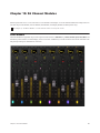
Chapter 10. S6 Channel Modules . . . . . . . . . . . . . . . . . . . . . . . . . . . . . . . . . . . . . . . . . . . . . . . . . . . . . . . . . . . . . . . . . . . . . 90
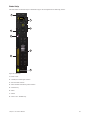
Fader Module . . . . . . . . . . . . . . . . . . . . . . . . . . . . . . . . . . . . . . . . . . . . . . . . . . . . . . . . . . . . . . . . . . . . . . . . . . . . . . . 90
Process Module . . . . . . . . . . . . . . . . . . . . . . . . . . . . . . . . . . . . . . . . . . . . . . . . . . . . . . . . . . . . . . . . . . . . . . . . . . . . . 95
Knob Module . . . . . . . . . . . . . . . . . . . . . . . . . . . . . . . . . . . . . . . . . . . . . . . . . . . . . . . . . . . . . . . . . . . . . . . . . . . . . . . 100
Display Module . . . . . . . . . . . . . . . . . . . . . . . . . . . . . . . . . . . . . . . . . . . . . . . . . . . . . . . . . . . . . . . . . . . . . . . . . . . . . 103
Contents
iv
Part I: Introduction
Chapter 1: Introduction
Pro Tools® | S6 is a professional, modular, ergonomically designed control surface for Pro Tools® | Software and
EUCON™-compatible digital audio workstations (DAWs). S6 uses the EUCON Ethernet protocol to provide fast, reliable data
transmission, and control multiple audio applications at once. S6 is flexible and scalable. Modules can be arranged in many different combinations, and additional modules can be added later to address workflow changes and/or increase the number of strips.
S6 is tightly integrated with all EUCON-compatible DAWs, providing access to many key commands, menu items, and controls
from the S6 control surface. The Master Module and Automation Module each have two Soft Keys sections that offer single-switch
access to automation, editing, session management, and other commands.
S6 provides substantial visual feedback to let you quickly identify tracks and their functions. Each strip inherits its color from the
audio application (if assigned), and module controls light in different colors for each function. The Display Module can display
high-resolution, multichannel colored meters, waveforms, and functions.
S6 offers six types of modules:
Master Module This is the central hub for S6 operations. It uses a touchscreen and other controls to let you select, mute, solo, enable
record and input, and edit track functions. The Master Module displays the Home, Tracks, Monitoring, and Settings Screens. All
S6 configurations must have one Master Module.
Automation Module This module includes Transport Controls, Jog/Shuttle Wheel, Attention Track Fader, and other controls.
Fader Module Each of its eight strips has a motorized fader, meter, navigation and automation switches, Attention key, and display.
Process Module Each of its eight strips has one knob section with multiple function switches.
Knob Module Each of its eight strips has four knob sections.
Display Module each of its eight strips can display metering, waveforms, and functions.
System Configurations
S6 offers two tiers of systems scaled for different installation sizes and requirements:
S6 M10 Built around the M10 Master Module, it is suitable for smaller configurations, accommodates 8 to 24 fader strips per frame,
supports up to two connected workstations, and does not support Display Modules.
S6 M40 Built around the M40 Master Module, it is suitable for larger configurations, more powerful than the S6 M10 system, supports up to eight connected workstations, and supports Display Modules.
Chapter 1: Introduction
1
For the S6 system in Figure 2, “16” refers to the number of fader strips in the system, and “5” refers to the number of knobs per
fader strip.
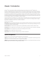
Figure 1 shows two arrangements for an S6 M10 8-5 configuration: One Fader Module (8 strips), one Process Module (1 knob per
strip), and one Knob Module (4 knobs per strip), for a total 5 knobs per strip.
Figure 1. Two 8-strip S6 M10 arrangements
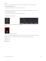
Figure 2 show three arrangements for an S6 M10 16-5 configuration: Two Fader Modules (16 strips), two Process Modules (1 knob
per strip), and two Knob Modules (4 knobs per strip), for a total 5 knobs per strip.
Figure 2. Three 16-strip S6 M10 arrangements with Master Modules to the left, in the center, and to the right of the Channel Modules
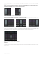
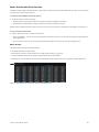
Figure 3 shows one arrangement for an S6 M40 32-9-D configuration: Four Fader Modules (32 strips), four Process Modules (1 knob
per strip), eight Knob Modules (8 knobs per strip), and four Display Modules (D), for a total 9 knobs per strip.
Figure 3. 32-strip S6 M40 arrangement with Display Modules
Options
A number of options are available including Fill Panels, Producers Desk, Keyboard Tray, Script Tray, SpeakerDecks, and VESA
Monitor Mount.
Chapter 1: Introduction
2
System Requirements and Compatibility
S6 Software version 1.2 requires Pro Tools 11.2 or later., and is also compatible with other EUCON™-aware applications.
For a list of supported applications, system requirements, and other compatibility information, visit:
http://www.avid.com/US/products/Avid-S6/tech-specs
Activation and Registration
As soon as you have assembled your S6 system and confirmed a successful hardware installation, activate your S6 system software
on-line. Use the alphanumeric code on the included S6 System Software Activation Card to activate and download all S6 system
software and documentation.
Be sure to Activate your purchase using the Activation card included with the Master Module so you can receive software updates
directly in your Avid account. Check your Avid account for system software updates, Workstation software, and monitor control
software (XMON EUCON software, and Studio Monitor Pro).
Registering
By registering, you become eligible to receive the following:
• Technical support information
• Software update and upgrade notices
• Hardware warranty information
About This Guide
This guide provides a basic overview of S6 features and functionality.
For complete instructions on connecting and configuring your system, see the S6 Installation Guide.
Conventions Used in This Guide
All of our guides use the following conventions to indicate menu choices and key commands:
:
Convention
Action
File > Save
Choose Save from the File menu
Control+N
Hold down the Control key and press the N key
Control-click
Hold down the Control key and click the mouse button
Right-click
Click with the right mouse button
The names of Commands, Options, and Settings that appear on-screen are in a different font.
The names of physical controls on the surface are shown in bold.
The following symbols are used to highlight important information:
User Tips are helpful hints for getting the most from your system.
Important Notices include information that could affect your data or the performance of your system.
Shortcuts show you useful keyboard or mouse shortcuts.
Cross References point to related sections in this guide and other Avid guides.
Chapter 1: Introduction
3
About www.avid.com
The Avid website (www.avid.com) is your best online source for information to help you get the most out of your S6
system. The following are just a few of the services and features available.
Product Registration Register your purchase online.
Support and Downloads Contact Avid Customer Success (technical support); download software updates and the latest online
manuals; browse the Compatibility documents for system requirements; search the online Knowledge Base or join the worldwide
Avid user community on the User Conference.
Training and Education Study on your own using courses available online or find out how you can learn in a classroom setting at
an Avid-certified training center.
Products and Developers Learn about Avid products; download demo software or learn about our Development Partners and their
plug-ins, applications, and hardware.
News and Events Get the latest news from Avid or sign up for an S6 demo.
Chapter 1: Introduction
4
Part II: Getting Started
Chapter 2: Introduction to the Touchscreen
Each S6 system must include a Master Module which, along with the Automation Module, forms the master section of the console.
The Master Module provides knobs, switches, and a touchscreen that let you quickly and intuitively do the following:
• Configure and manage your system
• Navigate through your session’s tracks
• Perform many recording, monitoring, routing, and mixing tasks
This chapter explains the gestures interpreted by the touchscreen.
Tap and Release
Tap the screen briefly and release without moving to select an object, activate its primary function, or toggle a parameter value between its two states. This is equivalent to a single mouse click.
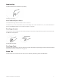
Touch, Hold, and Drag
Touch an object, hold briefly, then drag it to another location.
Touch, hold, and drag an object to a new location
Swipe
Touch and drag quickly left/right/up/down to do the following:
• Scroll the current page
• Move between different Settings pages
• Scroll between parameters in the Function Editor
• Scroll in the Track Matrix, Track Scroller, Meter Scroller, and Function Scroller
Swiping to scroll between pages
Chapter 2: Introduction to the Touchscreen
6
Stop Scrolling
Tap the touchscreen once and release to stop scrolling.
Touching to stop scrolling
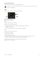
Touch and Hold, then Touch
Touch and hold an object, then touch others to add to a selection.
This makes it easy to select, record enable, mute, and solo multiple tracks in the Track Matrix View, even when Intercancel is selected in Track Selector Options (see “Track Selector Options” on page 36).
Two-Finger Stretch
Touch the screen with two fingers, then move them farther apart. This expands a collapsed Inserts function in the Function Scroller
(if it had two or more plug-ins).
Two-finger pinch and stretch
Two-Finger Pinch
Touch the screen with two fingers, then move them closer together. This collapses expanded plug-in inserts into the Inserts function
in the Function Scroller (if it had two or more plug-ins).
Double Tap
To enter a name for an on-screen item (such as a Layout or a Soft Key), double tap quickly in the Name field.
Chapter 2: Introduction to the Touchscreen
7
Chapter 3: First Time Setup
Connecting S6 to a Network
S6 modules communicate with digital audio workstations over an IP Ethernet network. All S6 modules and one or more workstations must connect to the supplied Ethernet switch.
Each S6 module and workstation requires a valid and unique IP address in the same range. This IP address can be created from either
of the following:
• DHCP (Dynamic Host Configuration Protocol) server in the Master Module
• External, third-party DHCP device, such as a standalone router or corporate network remote server
A Windows workstation name with any of the following characters will not be able to connect to S6: / \ [ ] " : ; |< > + = ,? * _
See http://support.microsoft.com/kb/228275 for more information.
Recommended Setup
Since S6 requires substantial bandwidth, and the network timing between modules is critical, we recommend installing S6 and your
workstation(s) on an isolated network/subnet using the Master Module’s internal DHCP server.
To connect S6 with your workstation(s) using the Master Module’s internal DHCP server:
1
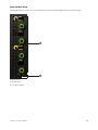
Connect the Master Module from Ethernet port 2 on its back panel to the supplied Ethernet switch.
2
Connect all other S6 modules and workstations to the same Ethernet switch. Do not connect any other equipment to this network.
3
Set your workstation network adapters to: Obtain IP addresses automatically by DHCP (default).
If you must connect your workstation to a Wide Area Network (WAN) to access the Internet or a corporate network, we recommend using a workstation with two Ethernet ports.
To connect your workstation to a WAN:
1
Connect one port to the WAN.
2
Connect the other port to the S6 Ethernet switch.
3
On the workstation that will connect to this S6 system, do one of the following:
• Mac: Click the WSControl icon in the Mac menu bar at the top-right of the screen.
– or –
• Windows: Right-click the WSControl icon in the system tray at the bottom-right of the screen.
WSControl icon in Windows system tray
Chapter 3: First Time Setup
8
4
Select Network Setup.
Setting the Desk ID in the Avid S6 WSControl Network Setup dialog
5
If your workstation has multiple networks attached, make sure the Network Interface selected is the one connected to your S6.
6
If you selected a new Network Interface, click Apply and Relaunch (Mac) or Apply and Restart (Windows) to reboot the workstation and restart WSControl.
See “Configuring Multiple S6 Systems on One Network” on page 15 to learn how to set the Desk ID for S6 and your workstations.
The Master Module internal DHCP Server uses the following default settings:
IP Address
Master Module
192.168.2.1
Host(s)
192.168.2.2 to 192.168.2.253
Default Gateway
192.168.2.254
DNS Gateway
192.168.2.254
Advanced Setup
To use a custom setup, you must have networking experience that may require accessing a WAN using a router, or installing the
entire S6 network as part of a corporate network infrastructure.
If you will use a third-party DHCP device, Avid recommends these routers from Cisco:
• Linksys E3200
• Linksys EA6500
Other routers have not reliably met the timing requirements of the S6 modules.
To connect S6 to a DHCP router or server:
1
Connect the Master Module from Ethernet port 1 on its back panel to the supplied S6 network switch.
2
Connect all other S6 modules to the same switch.
3
Connect the S6 network switch to a LAN port on the third-party DHCP router.
4
Connect your workstation(s) to either the S6 network switch or the LAN ports on the router.
If your workstation has multiple networks attached, make sure the Network Interface selected is the one connected to your S6.
See “Configuring Multiple S6 Systems on One Network” on page 15 to learn how to set the Desk ID for S6 and your workstations.
To connect S6 to a corporate network, consult your IT department for guidance.
Chapter 3: First Time Setup
9
Starting Up and Shutting Down the System
Starting Up the System for the First Time
To start up the system for the first time:
1
Make sure you have connected the S6 Power Strip to a UPS, power conditioner, or other switchable power source.
2
Turn on power to S6 from the power device.
3
When the system is fully started, if the touchscreen displays an End User License Agreement and the following message, you
must install updated software before you can continue:
Welcome to Avid S6
Before continuing, please choose Shut Down and then follow the instructions on the Registration and Activation cards included
in the front of the S6 Installation Guide to register and activate your purchase on-line so that you can download and install important software updates.
4
Shutdown/logout and check your Avid account for the most recent update.
5
Follow the installation directions that accompany the update.
6
Proceed to “Setting up S6 for the First Time” on page 11.
Shutting Down
To shut down the Master Module only:
Navigate the touchscreen to the Settings > About page and touch Shut Down.
To power off the entire system:
1
Shut down the Master Module.
Always shut down the Master Module before powering down the system!
2
Turn off power at the source device supplying power to the S6 Power Strip (UPS, power conditioner or other).
Chapter 3: First Time Setup
10
Setting up S6 for the First Time
You must first assemble and connect your S6 system according to the procedures in the S6 Installation Guide. You must also install
important S6 System Software before configuring the surface. See “Starting Up the System for the First Time” on page 10.
This section shows you how to do the following:
• Configure your S6 surface modules
• Connect S6 to your workstation(s)
• Enable EUCON connectivity in your audio application
Configuring the S6 Surface
After installing, rearranging, or removing modules you must configure your surface using the Master Module Settings > Surface
page.
To configure your S6 surface:
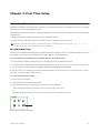
1
Press Home on the Master Module.
Home
Swap
Tracks Monitoring
Settings
WS
Layout
Mode
All
Mon A
App
Type
Flip
Mon B
Home switch on the Master Module
2
Touch Settings at the lower-right of the Home screen to display the Settings screen.
You can also press the Master Module Main Menu switch below Settings.
3
Touch Surface along the top of the Settings screen to open the Surface page.
Top of Settings screen
4
Touch Config at the bottom-left of the Surface screen.
Config, Next, Undo, Cancel, and Done appear at the bottom of the touchscreen during this process. The instructions refer to touching these controls but you can also press their Master Module Main Menu switches below them.
Home
Swap
Config
Config
WS
Layout
Mode
All
Mon A
App
Type
Flip
Mon B
Clear
Main Menu switches
Chapter 3: First Time Setup
C
11
5
Select your Frame Depth.
Select 4 if your frame uses Frame Chassis Small (supports one Knob Module per chassis) and 5 if Frame Chassis Large (supports
two Knob Modules per chassis).
Setting Frame Size in the Settings > Surface page
Helpful instructions appear in the Info area at the bottom of the screen.
6
Select your Frame Width.
Select the number of chassis assembled to form the system Frame.
Chapter 3: First Time Setup
12
7
Touch Next at the bottom-left to continue to the Modules page.
Modules
8
Drag the module stacks to the frame diagram until it matches your physical arrangement of modules. All allowable module combinations are displayed.
• To replace an existing module, drag a new module stack into that slot.
• To remove a module from your frame, drag the empty stack into that slot.
Surface modules in frame
9
Touch Next to continue.
All controls on the surface illuminate. If the controls do not light, check your connections made during installation.
Chapter 3: First Time Setup
13
10
To confirm that the module flashing in the Surface page is connected and correctly positioned, touch or press any physical control
on that module.
Its lights turn off, and the next module flashes. If a module’s lights do not turn off, check your assignments in the Settings > Surface
page. Touch Undo if you touch the wrong module.
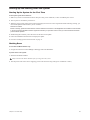
11
When all modules are confirmed, touch Next.
Figure 4 shows all modules confirmed except the Knob Modules on the far right, which are light gray.
Figure 4. Confirming modules
12
If you do not have Display Modules to assign, touch Done to accept the new arrangement and complete the process.
13
Drag each numbered Display Module icon to the frame diagram so it matches the number shown on the physical Display Module.
Figure 5. Assigning Display Modules
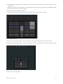
14
When you are done, touch Next.
Chapter 3: First Time Setup
14
15
Touch Done to accept the new arrangement and complete the process.
Figure 6. Finished Surface Arrangement
Configuring Multiple S6 Systems on One Network
Multiple S6 systems can operate on one network, but each S6 system and the workstation that controls it must be able to identify each
other. The Desk ID Surface option lets you assign a unique number for this S6 surface. You then assign that same number to the workstation that will control this S6.
If your installation has just one S6 system on a network, leave the Desk ID set to its default value of 1.
To set a unique Desk ID for this S6:
1
Touch the Local Options icon at the bottom-right of the Surface page. The Surface options open; Desk ID is the only entry.
Local Options
2
Drag the slider to set the desired number, which displays to the right of it.
Chapter 3: First Time Setup
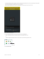
15
The message outlined in yellow in Figure 7 informs you that the Master Module must restart to enact this change. Touching Cancel avoids restarting and leaves Desk ID with its previous setting.
When the Master Module reboots, the previous arrangement is cleared and you must create a new one.
Figure 7. Desk ID Surface parameter
3
On the workstation that will connect to this S6 system, do one of the following:
• Mac: Click the WSControl icon in the Mac menu bar at the top-right of the screen.
– or –
• Windows: Right-click the WSControl icon in the system tray at the bottom-right of the screen.
WSControl icon in Windows system tray
4
Select Network Setup.
Chapter 3: First Time Setup
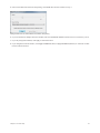
16
5
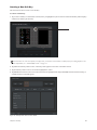
In the Avid S6 WSControl Network Setup dialog, set the Desk ID to the same number as in step 1.
Setting the Desk ID in the Avid S6 WSControl Network Setup dialog
6
If your workstation has multiple networks attached, make sure the Network Interface selected is the one connected to your S6.
7
If you only changed the Desk ID, click Apply to restart WSControl.
8
If you changed the Network Interface, click Apply and Relaunch (Mac) or Apply and Restart (Windows) to reboot the workstation and restart WSControl.
Chapter 3: First Time Setup
17
Connecting S6 to Workstations
In order to control an audio application with S6, you must first install Mac or Windows S6 Workstation software on the desired
computer. Then you connect that workstation to S6 using the Settings > Workstations page.
Multiple workstations can be connected to S6 at once, but only one is attentioned at a time. The attentioned workstation has exclusive access to the S6 surface. A workstation can be selected but not attentioned so you can derive information about the workstation, its applications, and EUCON version. Custom names can be assigned to connected workstations.
Before you can install S6 WSControl Software, you must remove any other EUCON or EuControl software present on the workstation.
To connect a workstation to S6:
1
Press Home on the Master Module.
2
Touch Settings at the lower right of the Home screen, or press its corresponding Main Menu switch.
3
To open the Workstations page, do one of the following:
• Touch Workstations at the top of the Settings screen.
– or –
• Press the WS switch on the Master Module (top-left Navigation Switch).
WS
Layout
Mode
All
Tracks
Type
Flip
L Spill
R Spill
Clear
Clip
WS switch
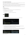
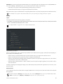
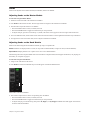
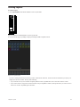
The Workstations screen appears, with the Network column on the left and the Connected column on the right.
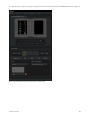
Figure 8. Top of Settings > Workstations page
4
Drag a workstation from the Network list over to a slot in the Connected list.
• The workstation name appears in the Connected slot, flashes as it connects, and then appears solid when it connects.
• The focused application (top-most application on that workstation) is listed on the lower right.
• If a previous workstation was connected to that slot, it is disconnected.
• The workstation is selected and attentioned, which is indicated by an orange (upper half) and blue (lower half) rectangular outline.
• In Figure 9, the workstation in the Connected list is selected and attentioned, and Pro Tools is the focused application.
Figure 9. Connected workstation
Chapter 3: First Time Setup
18
To connect multiple workstations at the same time:
Drag additional workstations from the Network list to the Connected list.
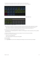
To change the attentioned workstation:
Touch a workstation in the Connected list without a blue outline.
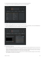
In Figure 10, GW-TEST1-HP is attentioned (blue outline).
To select a workstation to display its information at the bottom of the page:
Touch its entry in the Network list.
In Figure 10, GWMAC-2-Mac-Pro is selected (orange outline).
To enter a custom name for a workstation:
Double-tap the blank area at the top of the Connected box for that workstation, then enter a name using the on-screen keyboard.
1
2
2
3
Figure 10. Attentioned (1) and selected (2) workstations with Info area (3)
Chapter 3: First Time Setup
19
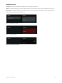
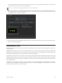
Workstation Status
Connected A connected workstation is indicated by a gray rectangle (see Figure 11).
Offline A connected workstation can become offline if WSControl was shut down properly on that workstation (see Figure 12).
Unreachable A connected workstation can become unreachable if the workstation or WSControl crashed, or the workstation’s
Ethernet cable was disconnected (see Figure 13).
Figure 11. Workstation connected
Figure 12. Workstation offline
Figure 13. Workstation unreachable
Chapter 3: First Time Setup
20
Enabling EUCON Connectivity
You must enable EUCON connectivity in your audio application to work with S6. The following instructions show how to enable
EUCON in Pro Tools.
To enable EUCON connectivity in Pro Tools:
1
Make sure you have connected S6 to your Pro Tools computer via Ethernet as explained in “Connecting S6 to a Network” on
page 8.
2
Launch Pro Tools.
3
Choose Setup > Peripherals, and click the Ethernet Controllers page.
4
Select Enable EUCON.
Pro Tools Setup > Peripherals > Ethernet Controllers
5
Click OK. After a quick scan, S6 is ready to use with Pro Tools. You do not need to configure any other Ethernet Controllers settings.
6
Connect the workstation running Pro Tools to S6. If you did not yet connect it, see “Connecting S6 to Workstations” on page 18.
7
Open a Pro Tools session if one is not already open.
8
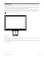
Click in any Pro Tools window to bring it into focus.
9
Verify that the Mix window displays a blue border around each Pro Tools track name.
10
Verify that the S6 displays track names and other relevant session data.
Chapter 3: First Time Setup
21
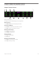
Chapter 4: Master Module Screens
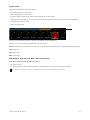
This chapter explains the four Master Module screens:.
Home Screen Lets you select and edit the Attention Track functions. Includes the Track and Meter Scrollers.
Parts of the Home screen may appear blank without an Attention Track assigned.
Tracks Screen Lets you quickly select tracks, attention a track to the Home screen, and enable track record, input, mute, and solo
functions. Displays categorized and color-coded tracks in the Track Matrix (if supported by the audio application).
Monitoring Screen Lets you assign monitor controls.
Settings Screens Let you set up the control surface, manage workstations, create and edit Soft Keys, and set S6 operational Preferences. The About page displays software version information and lets you Logout and Shutdown.
Figure 14. The four Master Module Screens: Home, Tracks, Monitoring, and Settings
To display other Screens from the Home screen:
Touch Tracks, Monitoring, or Settings or press their corresponding Main Menu switches.
To display the Home screen from any other screen:
Press Home (5 on left of Figure 15) on the Master Module.
Chapter 4: Master Module Screens
22
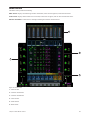
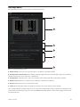
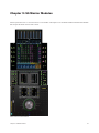
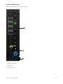
Home Screen
The Home screen provides the following:
Meter Scroller Displays track metering and other information, assists track navigation, and can attention tracks.
Track Scroller Displays status indicators for each track, assists track navigation, and can select and attention tracks.
Attention Track Editor Central area for selecting and editing the Attention Track functions.
1
Sel
Sel
In
In
2
Sel
Sel
In
In
Sel
Sel
In
In
Sel
Sel
In
In
3
4
Home
Swap
Config
5
WS
6
Layout
Mode
All
Mon A
Figure 15. Home screen
1 - Meter Scroller
2 - Attention Track Editor
3 - Attention Track Knobs
4 - Track Scroller
5 - Home Switch
6 - Back Switch
Chapter 4: Master Module Screens
23
Attentioning a Track
One track at a time can be attentioned to the:
• Attention Track Editor in the Home screen on the Master Module.
– and –
• Attention Track Fader on the Automation Module.
To attention a track from the Home screen:
Tap a track in the Track Scroller.
– or –
Tap a track in the Meter Scroller (see “Home Screen Options” on page 32 to set this preference).
To attention a track from the Fader Module:
Press the Attention key on the desired track’s Fader Module strip.
Solo
M
Mute
F
12
6
0
5
10
Attention key on a Fader Module strip
See “Attentioning Tracks” on page 58 for additional ways to attention tracks.
Chapter 4: Master Module Screens
24
The Attention Track Editor
In the Attention Track Editor, you select a function from the Function Scroller to display and edit in the Function Editor using the
Attention Track Knobs. Each function has its own color so their parameters are easy to distinguish.
Figure 16. Attention Track Editor
Function Scroller
The Function Scroller shows the Attention Track functions. You can select one function at a time to edit in the Function Editor.
While the selected function’s parameters take precedence, the Function Editor can display parameters from additional functions,
depending on the number of parameters and a preference setting (see “Home Screen Options” on page 32).
Figure 17. Function Scroller with Pan selected
To select a function from the Function Scroller to edit in the Function Editor:
Touch a function in the Function Scroller.
The selected function has an orange outline.
Chapter 4: Master Module Screens
25
Function Editor
The Function Editor can display eight columns of eight parameters each. The four parameters in the top or bottom half of each column can be assigned to the left or right Attention Track Knobs.
Figure 18. Function Editor
Assigning New Parameters to the Attention Track Knobs
The left and right Attention Track Knobs can each control four parameters, which must be from the same function.
You can assign different function parameters to the left and right Attention Track Knobs (see “Locking the Knobs” on page 28).
To assign a new bank of four parameters to the Attention Track Knobs:
1
Touch a function in the Function Scroller.
2
Touch a group of four parameters in the Function Editor.
Two brackets flash slowly around the selected parameters.
3
Before the brackets stop flashing, touch or turn any Attention Track Knob.
The four selected parameters are assigned to that side’s Attention Track Knobs, and the Function Editor provides the following
visual feedback:
• The parameter name, knob state, and value appear beside each Attention Track Knob.
• A left bracket (green in Figure 18) indicates the controls to its right are assigned to the left Attention Track Knobs.
• A right bracket (purple in Figure 18) indicates the controls to its left are assigned to the right Attention Track Knobs.
Chapter 4: Master Module Screens
26
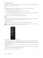
Using the Attention Track Knobs
Each Attention Track Knob section provides a dual-function knob with In and Sel switches. The knob lights when active, and in
certain contexts, it can also be pushed.
1
Sel
2
In
Attention Track Knob (2) with Sel and In switches (1)
In Toggles a parameter in and out, or between two values; it lights when active. The behavior depends on the audio application, and
not every parameter includes In switch functionality.
Sel Toggles the knob function or a secondary parameter value. For example, Sel can toggle Q and Frequency for an EQ plug-in,
or pre- and post-fader for a send.
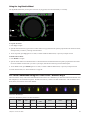
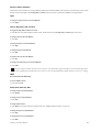
Function Editor Knob Types
Four virtual knob types are used to represent the different kinds of S6 parameters in the Function Editor. Figure 19 shows an EQ
plug-in that demonstrates each type.
1 Typically represents Q but can be used for other parameters that pertain to width. This knob type has two white marks at each end
that move symmetrically as Q changes.
2 Typically represents parametric filter gain but can be used for other parameters that boost and cut level from a center position.
This knob type has an outer ring that moves right or left from the top-center as the parameter boosts or cuts; its white mark shows
the level of boost or cut.
3 This knob type does not have an outer ring, which emphasizes that the white mark denotes position within a range of values not
level.
4 This knob type has an outer ring, which emphasizes that the white mark denotes level not position.
1
2
3
4
Figure 19. Knob types used in the Function Editor
Chapter 4: Master Module Screens
27
Locking the Knobs
When a new function is selected from the Function Scroller, its first parameter bank is assigned to the Attention Track Knobs. You
can prevent this automatic assignment by locking the Attention Track Knobs (left, right, or both sides) to their current parameters
(see Figure 20).
Since locking does not persist when a new track is attentioned, parameters from different tracks cannot be locked to the Attention
Track Knobs.
Figure 20. The right Attention Track Knobs are locked
To lock the Attention Track Knobs:
Touch an unlit Lock icon (above the Attention Track knob indicators in the Function Editor). The Lock icon lights, and selecting
new functions will not change these knob assignments.
To unlock the Attention Track Knobs:
Touch a lit Lock icon. The Lock icon dims, and selecting new functions will change these knob assignments.
If both the left and right Attention Track Knobs are locked, touching blocks of parameters in the Function Editor will not activate
the brackets used for knob reassignment.
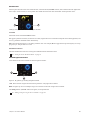
Functions with Additional Editing Features
The EQ, Dyn, Pan, Inserts, and Fader functions have additional features.
EQ, Dyn, and Pan
Drag EQ, Dyn, or Pan down into the Function Editor to display them graphically.
• You can touch Pan and drag its indicator(s) with one or two fingers, depending on the pan format.
• You cannot touch to edit the EQ or Dyn curves, but you can get graphical feedback as you adjust the Attention Track Knobs.
Graphs can be automatically displayed when a parameter is adjusted. For more information, see “Auto Show Function Graph on
Knob Touch” on page 32.
EQ (left), Dyn (center), and Pan (right) graphs in the Function Editor
Chapter 4: Master Module Screens
28
Inserts
Plug-in inserts can collapse into one Inserts function or expand to individual plug-ins in the Function Scroller.
To expand collapsed plug-in inserts:
Use the two-finger stretch gesture anywhere in the Function Scroller.
– or –
Select Inserts from the Function Scroller, and press the Attention Track Knob beside the plug-in you want to edit.
To collapse expanded plug-in inserts:
Use the two-finger pinch gesture anywhere in the Function Scroller.
– or –
Press Back on the Master Module.
Function Scroller with Inserts collapsed (left) and expanded (right)
Fader
Fader function with record and mute enabled
The Fader function shows the fader position of the Attention Track, and provides the following indicators (top to bottom):
Record Lights or flashes red to indicate record enable or record status (depends on audio application)
Input Lights green
Solo Lights yellow
Mute Lights orange
Chapter 4: Master Module Screens
29
Meter Scroller and Track Scroller
The Meter Scroller displays detailed metering, and the Track Scroller provides status information for each track. You can attention
a track from the Track or Meter Scroller.
To scroll the Track and Meter Scrollers by swiping:
Swipe the meters or tracks horizontally.
• Swiping scrolls at a speed proportional to the speed swiped, then gradually slows down.
• Touching while scrolling stops scrolling at that point, but does not attention the track.
Both the Track and Meter Scrollers use the Universe View. The Universe bar is the rectangular scroll indicator (see Figure 22).
To scroll using the Universe View:
Touch in the Universe View to scroll to that location.
• In the Track Scroller, you can touch a colored indicator in the Universe View to scroll to that track group (if supported by the
audio application).
• The size of the Universe bar is inversely proportional to the number of tracks in the focused audio application.
Meter Scroller
The Meter Scroller uses the following indicators:
• The Attention Track has a blue outline.
• Selected tracks can have an orange outline (see “Home Screen Options” on page 32).
• A selected Attention Track has an orange (top half) and blue (lower half) outline.
• Tracks that are record enabled or are actively recording flash or light solid red in Pro Tools (depends on audio application).
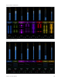
Figure 21. Meter Scroller with Universe bar; Audio 6 is the Attention Track
Chapter 4: Master Module Screens
30
Track Scroller
The Track Scroller uses the following indicators:
• The Attention Track has a blue outline.
• Selected tracks have an orange outline.
• A selected Attention Track has an orange (top half) and blue (lower half) outline.
• Tracks that are record enabled or are actively recording flash or light solid red in Pro Tools (depends on audio application).
• Each track has a small level meter.
• Tracks dim when muted.
Figure 22. Track Scroller with Universe bar; Bass is record enabled, muted, and attentioned
The top of each track provides the following indicators (left to right):
Record Tracks that are record enabled or are actively recording flash or light solid red in Pro Tools (depends on audio application).
Input Lights green
Solo Lights yellow
Mute Lights orange
Attentioning a Track From the Meter and Track Scrollers
To attention a track from the Meter and Track Scrollers:
• Tap a track or meter.
The track is assigned to the Attention Track Editor and the Attention Track Fader on the Automation Module.
See “Home Screen Options” on page 32 to enable parameters that interact with the Meter Scroller.
Chapter 4: Master Module Screens
31
Home Screen Options
To open the Home Screen Options:
Touch the Local Options icon on the bottom-right of the Home screen.
To close the Home Screen Options:
Touch the Local Options icon again or touch outside the Home Screen Options page.
Home Screen Options with Local Options icon on the right
Attention Tracks from Meter Scroller
This option toggles whether or not a track can be attentioned from the Meter Scroller.
Display Selection/Attentioned Track Border on Meter Scroller
This option lets you toggle whether or not selected and attentioned tracks are outlined in the Meter Scroller.
Track Scroller Follows Attentioned Track
The Track Scroller shows the Attention Track at its left border.
Link Meter Scroller to Track Scroller
Scrolling the Track Scroller scrolls the Meter Scroller so they show the same track, and vice versa.
Knob View
All Functions
The Function Editor displays all functions. Swiping the Function Editor horizontally scrolls to other functions.
Selected Function
The Function Editor displays just the selected function.
Auto Show Function Graph on Knob Touch
When enabled, adjusting a function that has a graph display automatically displays the graph in the Home screen, temporarily replacing the current view. The graph display disappears after you let go of the knob.
Chapter 4: Master Module Screens
32
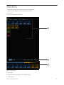
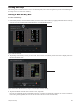
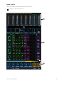
Tracks Screen
The Tracks screen lets you:
• Display different track types (if supported by your audio application).
• Attention tracks to the Home screen and Attention Track Fader.
• Select tracks.
• Enable record, input, solo, and mute.
1
2
3
Figure 23. Tracks screen
1 - Track Matrix
2 - Attention, Select, Record, Input, Solo, and Mute controls
3 - Track Scroller
Chapter 4: Master Module Screens
33
Displaying Tracks
If your audio application supports track types, you can choose which types to display in the Track Matrix.
To change the track type displayed:
Touch a different track type from the tabs at the top of the Tracks screen.
– or –
Swipe the Track Matrix horizontally to scroll between track types.
If your audio application also supports track colors, these are two powerful methods by which to differentiate and locate tracks.
For example, Figure 23 shows All, Audio, Instrument, Aux, and Master track types for Pro Tools.
Track Matrix Controls
The Attention, Select, Record, Input, Solo, and Mute controls (2 in Figure 23) are exclusive: One is always active, and only one can
be active at a time.
Attention
To attention a track:
Touch Attention, then touch a track.
• The display changes to the Home screen unless Auto-Bank to Attentioned Track is selected (see “Surface” on page 39).
• This track is assigned to the Attention Track Editor and the Automation Module’s Attention Track Fader.
• The Attention Track has a blue outline in the Track Matrix, Track Scroller, and Meter Scroller.
A selected Attention Track has an orange (top half) and blue (lower half) outline.
Select, Record, Solo, Input, and Mute
To select tracks or enable them for recording, input, mute, or solo:
1
Touch Select, Record, Solo, Input, or Mute to enable that control.
2
Touch one or more tracks.
3
Touch a selected or enabled track to deselect or disable it.
To quickly select or enable multiple tracks:
1
Touch Select, Record, Solo, Input, or Mute to enable that control.
2
Do one of the following:
Touch and hold a track, then touch others to add to the group.
– or –
Touch a track and drag over a row or column.
See “Channel Selection Mode” on page 36.
Selected tracks have an orange outline in the Track Matrix, Track Scroller, and Meter Scroller (see “Home Screen Options” on
page 32).
Chapter 4: Master Module Screens
34
When tracks are record enabled:
• They are armed for recording.
• Rec flashes red on their Fader Module strips.
• Tracks that are record enabled flash red in Pro Tools (depends on audio application).
• Fader in the Function Scroller and entire track in the Meter Scroller flash red in Pro Tools.
Pro Tools indicators that flash red when record enabled, light solid red during recording.
Record indications are controlled by each audio application.
When tracks are enabled for input monitoring:
• Their track audio is routed directly from input to output, bypassing track plug-ins and functions.
• Input lights on their Fader Module strips.
• Their track Input indicators light green in the Track Matrix, Track Scroller, and Fader in the Function Scroller.
When tracks are soloed:
• Those tracks are audible, all others are muted.
• Solo lights yellow on Fader Module strips with soloed tracks, and Mute lights orange on other strips.
• The track Solo indicator lights yellow in the Track Matrix, Track Scroller, and Fader in the Function Scroller.
When tracks are muted:
• Mute lights orange on their Fader Module strips.
• The Mute indicator lights orange and the track dims in the Track Matrix, Track Scroller, and Fader in the Function Scroller.
Clear
Touch Clear to clear any tracks that have been enabled for record or input, muted, or soloed. This control appears only when Record,
Input, Solo, or Mute is selected.
Track Scroller
See “Track Scroller” on page 31 to learn about its displays and behavior. Note that attentioning a track from the Track Scroller in
the Tracks screen keeps the display on the Tracks screen.
Chapter 4: Master Module Screens
35
Track Selector Options
Figure 24. Track Scroller with Local Options icon at far right
To display the Track Selector Options:
Touch the Local Options icon at the lower right of the Tracks screen.
To close the Track Selector Options:
Touch the Local Options icon again or touch outside Track Selector Options.
Track Selector Options
Channel Selection Mode
Channel Selection Mode offers Sum and Intercancel functionality:
Sum Each selected track is added to the existing selection(s). Selecting a selected track deselects it.
Intercancel Each selected track replaces the previous selection. Selecting a selected track does not deselect it. In Intercancel mode,
you can select multiple tracks by touching and holding a track while touching others.
Solo Switch
Solo functions are implemented by the audio application.
Solo Switch offers Intercancel and Sum functionality:
Sum Each soloed track is added to the existing selection.
Intercancel Each soloed track replaces currently soloed track(s).
Chapter 4: Master Module Screens
36
Position
This determines which track to display at the top-left of the Tracks screen.
Always Start With Channel 1 on All Page Displays track 1 at top left in the Track Matrix.
Last Position of Track Selector Displays the Track Matrix as it appeared most recently.
Attentioned Track Displays the attentioned track at the top-left of the Track Matrix.
Display Breaks On Track Color
When selected, tracks with assigned colors appear on their own line.
Auto-Bank to Attentioned Track
When selected, each track attentioned automatically banks the surface so the track appears on the right-most strip if the Automation
Module is to the right of the Fader Module(s). The track appears on strip 1 if the Automation Module is to the left of the Fader
Module(s). The display remains on the Tracks screen.
Show Home Screen on Track Attention
When selected, attentioning a track in the Tracks screen automatically displays that track in the Home screen. When unselected, the
Home screen is not automatically displayed when a track is attentioned in the Tracks screen.
Chapter 4: Master Module Screens
37
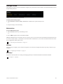
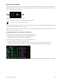
Monitoring Screen
To display the Monitoring screen, do one of the following:
From the Home screen, touch Monitoring or press its corresponding Main Menu switch on the Master Module.
– or –
Press the lower-right Setup switch on the Master Module.
The Monitoring screen can be locked to the current audio application using the Setup switch on the Master Module (see “Monitor
Select Controls and Display” on page 85).
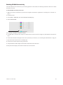
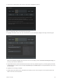
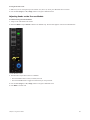
Figure 25. Monitoring screen with Sources on and off
Source Select and other choices are determined by the focused monitoring application (whether XMON EUCON, or Studio Monitor Pro 2).
To toggle a Source on and off:
In the Source row, touch the rectangular area below the source name.
Blue sources are on, dimmed sources are off. In Figure 25 CD1, FX, Main, and Foley are on.
Chapter 4: Master Module Screens
38
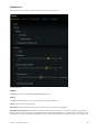
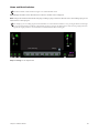
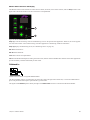
Settings Screen
The Settings screen lets you connect workstations, configure your system, add or remove modules, create and edit Soft Keys, and set
S6 operational preferences.
Settings screen with Preferences page selected
To display different Settings pages:
Touch Workstations, Surface, Softkeys, Preferences, or About at the top of the Settings screen.
– or –
Swipe the Settings screen horizontally.
Workstations
To open the Workstations page:
Touch Workstations at the top of the Settings screen.
– or –
Press the WS navigation switch on the Master Module.
Multiple workstations can be connected to S6 at once, but only one is attentioned at a time. The attentioned workstation has exclusive access to the S6 surface. A workstation can be selected but not attentioned so you can derive information about the workstation, its applications, and EUCON version.
See “Connecting S6 to Workstations” on page 18.
Surface
This page lets you configure your S6 surface arrangement. You will need to configure the surface only when you first set up or
modify S6.
See “Configuring the S6 Surface” on page 11.
Soft Keys
S6 provides a Soft Key Editor for creating and managing Soft Keys on the Master Module and Automation Module.
See Chapter 5, “Soft Keys.”
Chapter 4: Master Module Screens
39
Preferences
This page lets you set global S6 surface, workstation, and transport preferences.
Surface preferences
Surface
The Surface section contains Banking and Brightness parameters.
Banking
Two Mode buttons determine how the surface responds to banking commands.
8 Strips The system banks by eight strips.
Whole Surface The system banks by the number of fader strips in the current S6 arrangement.
Auto-Bank to Selected Track When selected, selecting a track (in the Tracks screen, or on-screen in the DAW) automatically
banks the surface so that track appears on the right-most strip if the Automation Module is to the right of the Fader Module(s). The
track appears on strip 1 if the Automation Module is to the left of the Fader Module(s). The display remains on the Tracks screen.
Chapter 4: Master Module Screens
40
Brightness
These settings manage the brightness of various S6 components, and can help save energy.
Auto When selected, light sensors at the top of the Master Module measure ambient illumination to set appropriate brightness
levels for the OLED, LED, Display Module, and touchscreen.
Touchscreen Touch and drag the slider to set the desired brightness.
OLED, LED, Display Module Touch and drag the slider to set their desired brightness.
Console Timeout Touch and drag the slider to set the desired time for displays to sleep when the system is inactive.
Soft Key LEDs Enabled When selected, LEDs in Soft Key switches on the Master and Automation Module light when enabled/ac-
tive. When unselected, Soft Key LEDs remain unlit regardless of their active or inactive state.
Workstation
General
These features may not be implemented by all audio applications, so consult your documentation.
Workstation Follows Knob Set Changes The workstation displays the controls selected on the Knob Module or Process Module.
Open Plug-ins on Workstation When Editing Opens plug-in windows on the workstation when editing a plug-in on the surface.
Close Plug-ins on Workstation When No Longer Editing Closes plug-in windows when another function is selected on the surface.
Workstation preferences
Solo
Solo modes are implemented differently by each audio application.
In Pro Tools, Solo Mode has three settings:
Solo In Place Mutes all tracks except the soloed track(s).
After-Fader Listen Solo signal is derived after the fader (AFL).
Pre-Fader Listen Solo signal is derived before the fader (PFL).
Chapter 4: Master Module Screens
41
KVM Switch S6 can be used with specific KVM switches to let a single display follow S6 workstation focus. In the KVM Switch section of the S6 Settings > Preferences screen, you can enable serial control of either of the following:
• Gefen (http://www.gefen.com/kvm/dproductlisting.jsp?listingCategory=Switchers)
• Guntermann and Drunck (http://www.gdsys.de/en/products/kvm-switches/)
When either of these options is enabled and the corresponding KVM switch is connected, the display follows S6 Workstation focus.
If your KVM does not respond, contact Avid Customer Service for help with specific settings that may be required.
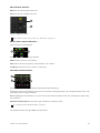
Display
Layout
The Display Module has the following display layout options:
• Large Meters, Large Waveforms, Meters and Waveforms, Meters and Function, Waveforms and Function, Waveforms and Dual
Function, and Waveforms and Dual Function + Route.
See “Display Module” on page 103 to view examples of display layout.
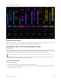
Display Module layout options
When any Function display mode is enabled, Display Modules show different functions, graphs, and knobs/values depending on
the strip and its associated display state.
• When a function is selected that doesn't have a graph associated with it, up to eight encoder knobs are shown.
• When a selected function has a graph (such as EQ), it is displayed simultaneously.
• When any of the Dual Function display modes is enabled, the Function view splits into an upper and lower view. The currently
selected function is shown above, and Pan below.
• When Waveforms and Dual Function + Route is enabled, the current input and output assignments for each track are shown
below the functions.
Touching or adjusting a knob changes the display to the value for that knob (it switches back to parameter view as soon as you release the control).
Waveform Zoom
You can adjust the zoom of waveforms shown on Display Modules from 1 second up to 60 seconds. Waveform Zoom be adjusted
during playback.
On the Master Module, the Display 1 switch zooms out by 10 seconds, and Display 2 zooms in 10 seconds. Hold the Master Module Shift switch while pressing Display 1 or Display 2 to zoom out or in 1 second, respectively.
Chapter 4: Master Module Screens
42
Chapter 5: Soft Keys
S6 provides a Soft Key Editor in the Settings screen for creating and managing Soft Keys on the Master Module and Automation
Module. You can add, delete, rename and color Soft Keys. EUCON commands and page jumps can be assigned to each Soft Key.
Full-color icons can be assigned to both the active and inactive states, and background colors and names can be changed.
Keyboard commands (shortcuts), multi-EUCON commands, and multi-DAW macros are not supported.
Quick Start
To get started using the Soft Key Editor,
To get to the Soft Keys page, do the following:
1
Press the Settings switch in the Master Module Navigation switch section.
2
Tap Soft Keys at the top of the screen.
3
Use the Help Text instructions at the bottom of the default Soft Key Editor page (see Figure 26 on page 44).
4
For step-by-step instructions to create a new Soft Key, see “Creating Soft Keys” on page 45.
Chapter 5: Soft Keys
43
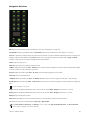
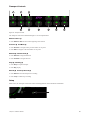
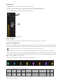
Soft Keys Editor
The default Soft Keys Editor screen provides the following main sections.
A
B
C
D
E
F
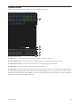
Figure 26. Soft Key Editor default screen
A – Module Selector Touch to choose to target Soft Keys on the Master or Automation Module
B – Soft Key Banks and Commands Displays Soft Key banks and assignments on the selected module, and provides commands to
edit bank name and color, Insert, Add, Clear, or Delete banks.
C – Soft Key Editor Command to Insert, Add, Clear, and Delete Soft Key blocks that make up the Soft Key definition.
D – Modifier Locks Modifier keys to define and access additional commands from a Soft Key.
E – Help Text Instructions for how to use the Soft Key Editor.
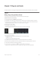
F – Factory Reset the Soft Key Editor to its default set of Soft Keys (any custom Soft Keys will be deleted).
Once you begin editing or creating Soft Keys, the lower section of the Soft Key Editor changes to different views depending on the
current task. To exit the Soft Keys page at any time, press Home on the Master Module or select another Settings screen from the
top of the touchscreen.
Chapter 5: Soft Keys
44
Creating Soft Keys
This section gives an example of how to create a new Soft Key bank, how to define navigation keys for the new bank, and gives
an example of how to create a new Soft Key.
Creating a New Soft Key Bank
To create a new Soft Key:
1
In the Soft Key Editor, select the module on which you want to create a new Soft Key by tapping the Module Selector at the top
of the page and choosing Automation Module Soft Keys, or Master Module Soft Keys.
Figure 27. Module Selector
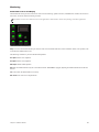
2
Tap the image of the Soft Key screen you want to edit. The selected set is outlined in yellow and its name is displayed below in
the Bank commands section.
Figure 28. Automation Module Soft Keys, Right set, selected (Add command, below)
3
Tap Add in the Bank commands section to create a new, empty bank.
New banks are added after the last existing Bank in that set. New banks are automatically numbered. (To create a new bank between existing banks, tap Insert; the new bank will be inserted after the currently selected bank.)
Chapter 5: Soft Keys
45
4
Name the bank and choose a text color by doing the following:
• Double-tap the name field (to the left of the Color Picker) and enter a name for the bank using the on-screen touch keyboard.
Tap Enter close the on-screen keyboard.
• Tap the Color Picker and tap to select a color for the bank name text. Tap Done (or tap anywhere outside the Color Picker) to
close it and return to the Soft Key Editor.
Figure 29. Naming a new Soft Key bank
Adding Navigation Keys to a Bank
Navigation keys use the Page commands to navigate among banks of Soft Keys. In this example, we will define keys to navigate
to the previous and next page of banks.
To add navigation keys to a bank:
1
In the three keys across the bottom of the bank, tap to select the left key as shown in Figure 30.
Figure 30. Selecting a key for page navigation
2
Tap Add in the Soft Key Editor section.
Chapter 5: Soft Keys
46
3
Tap the newly created Soft Key block to select it (the block is highlighted in yellow).
Figure 31. Soft Key Editor after a command block has been added
4
Tap Page at the Bottom of the screen. The command block you just added displays Page, and the Page commands appear.
Figure 32. Page commands
Make sure the Section to Change selector shows the correct set of Soft Keys (such as Automation Module Right Soft Keys). If
necessary, tap and choose a different set.
5
Tap the Action selector and choose the desired action (for the “left” key selected in Figure 30, you would typically choose Go
to Previous Page). If instead you choose Jump to Specified Page, the Available Pages list to the right illuminates; tap to select
the desired page.
6
Tap Done to close the Page commands.
7
Double-tap the name field and enter a text label for the Soft Key (such as “Left”) using the on-screen touch keyboard. Tap
Enter to close the on-screen keyboard.
Chapter 5: Soft Keys
47
8
Repeat the previous steps for the “right” navigation key of the new bank, defining it to Go to Next Page as shown in Figure 33.
Figure 33. Left and Right navigation keys defined for a Soft Key bank
Chapter 5: Soft Keys
48
Creating a New Soft Key
This section shows how to create a new Soft Key.
To create a new Soft Key:
1
Tap to select a Soft Key in a bank. When selected, the key is highlighted in yellow. The lower half of the Soft Key Editor displays
commends for defining the Soft Key.
Figure 34. A selected Soft Key
You do not have to create new Soft Keys in empty slots, you can also create them in secondary layers for existing Soft Keys. For
more information, see “About Modifier Locks” on page 51.
2
Tap Add in the Soft Key Editor section. A Soft Key block appears in the center of the Editor section.
3
Tap the Soft Key block to select it. It becomes highlighted in yellow.
4
Tap EUCON at the bottom of the screen. The block becomes highlighted and displays EUCON, and the hierarchical listing of
available EUCON commands appears.
Figure 35. Soft Key Editor with one block added
Chapter 5: Soft Keys
49
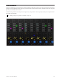
5
Use the hierarchical EUCON command lists to navigate to and select the desired command.
For example, scroll to and then tap Window Menu, then scroll to and tap Big Counter.
Figure 36. Selecting Big Counter
6
Tap Done (or tap the Soft Key block) to close the EUCON command menus.
7
Tap Text/Icon Display Mode and select how you want text and/or icons displayed for the Soft Key. Choices include Not Used (no
text or icon), Icon Only, and other options for Soft Key text and icon appearance.
Figure 37. Text/Icon Display Modes
8
Under State, do the following:
• Tap the Inactive/Active selector to choose which state you want to define first. (Some commands only have an inactive state.)
• Tap the Icon display (it will be blank for newly created Soft Keys), then use the displayed library to choose an icon for the current state. The Icon palette can be filtered to show All icons or Pro Tools icons, and can be scrolled up, down, left, and right.
Tap Done (or tap outside the Icon palette) to close it and return to the Soft Key Editor.
• Double-tap the text field (directly below the Icon display) and enter a text label for the Soft Key using the on-screen touch keyboard. Tap Enter to close the on-screen keyboard.
Chapter 5: Soft Keys
50
• Tap the Color Picker and tap to select a color for the text to appear in the currently selected state. Tap Done (or tap outside the
Color Picker) to close it and return to the Soft Key Editor.
You can save custom colors by dragging the modified color box onto the palette.
• Repeat for the other state (if you defined display characteristics for the Inactive state, now choose Active and choose an icon,
enter a name and choose a color). In the example Soft Key we created for the Big Counter, we defined text for the Active state
as “Hide Big Counter” as shown in Figure 38.
Figure 38. Active state example
9
To exit the Soft Keys page, press Tracks on the Master Module, or select another Settings screen from the top of the touchscreen.
Soft Keys are saved automatically.
About Modifier Locks
New Soft Keys do not need to be created in new banks or empty Soft Keys, they can also be created in modifier-driven layers for
existing Soft Keys.
The Modifier Locks section lets you “lock” the available modifier keys on (pressed) to create Soft Keys that become available while
a modifier key is pressed. This lets you create new Soft Keys in the same position as an existing Soft Key but which only becomes
available when holding down the associated modifier switch on the Fader Module.
For example, in the previous section we defined a new Soft Key to show and hide the Pro Tools Big Counter window. To have an
additional window display choice (such as Track Arming) available on that same Soft Key, and in the same Soft Key bank, tap Shift
in the Modifier Locks section (a check appears indicating it is locked on), then select and define the Soft Key to open and close the
Track Arming window.
Once defined, you can toggle the Soft Key view between modifier “layers” by holding down the associated modifier. For example,
in default view our new bank shows our Big Counter Soft Key on key 1. Holding down Shift on the Fader Module shows our Track
Arming command on the same key, in the same bank.
Chapter 5: Soft Keys
51
Part III: Using S6
Chapter 6: Common S6 Tasks
This chapter shows you how to perform the following tasks using S6:
• Nudge and bank tracks
• Select tracks
• Record enable tracks
• Attention a track
• Set track automation modes
• Use Jog, Shuttle, and other Transport Controls
Nudging and Banking
Several keys on the Master Module Navigation section nudge and bank channels assigned to the surface.
For additional ways to arrange tracks on the surface, see Chapter 8, “Layouts.”
L Spill
R Spill
Clear
Clip
1
Mixer
Close
Clear
Solo
2
3
Home
End
Display 1
4
Display 2
Settings
Sel
In
Shift
5
Config
Figure 39. Nudge left (1), Nudge right (2), Bank left (3), Bank right (4), and Shift (5) switches
Nudge
To nudge left by one track:
Press ◄/Mixer.
To nudge right by one track:
Press ►/Close.
Chapter 6: Common S6 Tasks
53
Bank
The number of tracks to bank and other useful options are set in the Settings > Preferences page (see “Banking” on page 40).
To bank left:
Press ◄◄/Home.
To bank right:
Press ►►/End.
The following commands refer to the Shift Navigation Switch (5 in Figure 39), not the Shift key on the Fader Module or computer
keyboard.
To bank so the first track appears on the first (left-most) strip in the current S6 arrangement:
Press Shift + ◄◄/Home.
To bank so the last track displays on the last (right-most) strip in the current S6 arrangement:
Press Shift + ►►/End.
Selecting Tracks
You can select tracks from the Fader Module and the Master Module. Selected tracks have an orange outline in the Track Scroller
and Track Matrix.
Sum and Intercancel modes affect track selection on the Fader Module and Track Matrix. See “Channel Selection Mode” on
page 36 for more information.
Selecting Tracks Using the Fader Module
The steps in this section refer to the Fader Module Shift and Ctrl Track Color / Modifier keys at the bottom of Fader Module strips
1 and 2, respectively. These keys help execute Pro Tools commands only, and they are equivalent to their QWERTY counterparts.
Fader Module Shift and Ctrl keys
To select a single track from the Fader Module:
Press Select on the desired strip.
Select
M S
Swap
Menu
LG
Solo
M
Mute
F
Fader Module Select switch
Chapter 6: Common S6 Tasks
54
To select sequential tracks on the Fader Module:
1
Press Select on the desired track.
2
Press Shift + Select on the last track.
To select multiple discontiguous tracks:
1
Press Select on the desired track.
2
Do one of the following:
• In Sum mode, press Select on additional tracks.
• In Intercancel mode, press Command + Select (Mac) or Ctrl + Select (Windows) on additional tracks.
To select all Pro Tools tracks on the surface:
Hold down Option (Mac) or Alt (Windows), and press Select on any track.
Selecting Tracks Using the Master Module
To select tracks using the Master Module:
1
Display the Tracks screen by touching Tracks or pressing its switch at the bottom of the Home screen.
2
Touch Select.
Select tab on the Tracks screen
3
Touch a track in the Track Matrix to select it.
Track Matrix
4
To select multiple tracks, do one of the following:
• In Sum mode, touch additional tracks to select them.
• In Intercancel mode, touch and hold a track and touch additional tracks to select them (also works in Sum mode).
Chapter 6: Common S6 Tasks
55
Record Enabling Tracks
To record in an audio application, the track must be record enabled and the Transport must be armed for recording.
The following flash red when a track is record enabled:
• Rec switch on that Fader Module strip.
• Recording indicator in the Track Matrix, Track Scroller, and Fader in Function Scroller.
• The entire track in the Track and Meter Scrollers.
The indicators that flash red when record enabled light solid red during recording.
To arm the Transport for recording:
On the Automation Module, press Record on the Transport.
You can record enable tracks using the Fader Module and the Master Module.
Record Enabling Tracks Using the Fader Module
The steps below refer to the Fader Module Shift and Ctrl Track Color / Modifier keys at the bottom of Fader Module strips 1 and
2, respectively. These keys help execute Pro Tools commands only, and they are equivalent to their QWERTY counterparts.
To record enable tracks from the Fader Module:
Press Rec on the desired tracks.
To disable a record-enabled track from the Fader Module:
Press a red flashing Rec switch.
Select
M S
Swap
Menu
LG
Solo
M
Mute
F
Fader Module record switch
To record enable contiguous tracks from the Fader Module:
1
Press Rec on the first track.
2
Hold down Shift and press Rec on another strip.
To record enable all Pro Tools tracks on the surface:
Hold down Option (Mac) or Alt (Windows), and press Rec on any track.
To record enable all selected Pro Tools tracks on the surface:
Hold down Option + Shift (Mac) or Alt + Shift (Windows), and press Rec on any track.
If the track you pressed Rec on was not selected, it is still record enabled.
Chapter 6: Common S6 Tasks
56
Record Enabling Tracks Using the Master Module
To record enable tracks using the Master Module:
1
To display the Tracks screen, touch Tracks at the bottom of the Home screen.
2
Touch Record (above the Track Scroller).
Record tab in the Tracks screen
3
Touch the desired tracks in the Track Matrix.
Track Matrix with tracks enabled for recording
To disable a record-enabled track using the Master Module:
1
Touch Record.
2
Touch a record-enabled track.
To disable all record-enabled tracks using the Master Module:
1
Touch Record.
2
Touch Clear.
Chapter 6: Common S6 Tasks
57
Attentioning Tracks
You can display, edit, and control the Attention Track using the Attention Track Editor (Home screen) and Attention Track Fader
(Automation Module).
To attention a track from the Fader Module:
Press the desired track’s Attention key on the Fader Module.
Solo
M
Mute
F
12
Attention key on Fader Module strip
To attention a track from the Home screen on the Master Module:
Tap a track in the Track Scroller.
– or –
Tap a track in the Meter Scroller (see “Home Screen Options” on page 32 to set this preference).
To attention a track from the Tracks screen on the Master Module:
1
Navigate to the Tracks screen by touching Tracks at the bottom of the Home screen.
2
Select Attention.
Attention tab in the Tracks screen
3
Tap a track in the Track Matrix or the Track Scroller.
Track Matrix
If the track is also selected, it has a two-color outline: orange (upper half) and blue (lower half).
Chapter 6: Common S6 Tasks
58
Setting the Track Automation Mode
To set the track automation mode:
On a Fader Module, press F on the desired strip repeatedly to cycle through the automation modes. While writing in Latch mode,
press F to Auto Match out.
To toggle Trim Automation on and off:
On a Fader Module, press M.
This table provides the automation modes for any S6 knob or switch with automation LEDs.
0 = unlit
1 = lit
* = flashes
Automation Mode
Red LED
Green LED
Off
0
0
Read
0
1
Touch
1
0
Latch
1
0
Touch/Latch
1
0
Write
1
0
Preview
0
*
Off + T
0
1
Read + T
0
1
Touch + T
1
1
Latch + T
1
1
Touch/Latch + T
1
1
Write + T
1
1
The red LED flashes while writing automation.
The green LED flashes in Preview mode.
Chapter 6: Common S6 Tasks
59
Using the Transport and Jog/Shuttle Controls
The Automation Module provides a Transport section and Jog/Shuttle Wheel.
Using the Transport Controls
1
2
Setup
3
BACK +
R MODE
BACK
LOC
LOOP
4
5
6
7
8
9
Figure 40. Transport controls
The Transport controls not identified in Figure 40 are not implemented.
Return to Zero (1)
Press Return to Zero to return to the beginning of the session.
Previous (2) and Next (3)
Press Previous to navigate to the previous marker or cue point.
Press Next to navigate to the next marker or cue point.
Rewind (4) and Forward (5)
Press Rewind to navigate backward.
Press Forward to navigate forward.
Stop (6) and Play (7)
Press Stop to stop the transport.
Press Play to play.
Record (8) and Loop Record (9)
Press Record to arm the transport for recording.
Press Loop to enable loop recording.
Chapter 6: Common S6 Tasks
60
Using the Jog/Shuttle Wheel
The Jog/Shuttle Wheel lets you navigate a session at varying speeds, and zoom horizontally or vertically.
Function
Move Selection
+
-
Scroll Horizonta
Zoom Horizonta
Trim
2
1
Scroll Vertical
Zoom Vertical
Shuttle
Jog
Shift
Jog/Shuttle Wheel with Jog (1) and Shuttle (2) switches
To Jog with the wheel:
1
Press Jog so it lights.
2
Spin the wheel clockwise to jog forward or counterclockwise to jog backward. The speed is proportional to the wheel movement,
and stops when you remove your finger from the wheel.
3
To exit Jog mode, press Jog again so it is unlit, or enable a different Wheel mode, or press any Transport switch.
To Shuttle with the wheel:
1
Press Shuttle so it lights.
2
Spin the wheel clockwise to shuttle forward or counterclockwise to shuttle backward. The speed is proportional to the wheel
movement. Shuttle continues after you remove your finger (and after the wheel stops) at the initiated speed.
3
To exit Shuttle mode, press Shuttle again so it is unlit, or enable a different Wheel mode, or press any Transport switch.
To zoom with the wheel, see “Scroll and Zoom” on page 88.
Pro Tools Commands Using the Track Color / Modifier Keys
This section lists a variety of Pro Tools commands that use the Track Color / Modifier keys at the bottom of the Fader Module. Note
that multiple keys can be held down together. The table lists each key’s function for Mac and Windows. The commands refer to
knobs, faders, and switches on the Fader Module.
Track Color / Modifier keys
Track Color / Modifier Key functions for Mac and Windows
Shift
Ctrl
Opt/Alt
Command/
Win
User 1
User 2
Cancel
OK
Mac
Shift
Control
Option
Command
not implemented
not implemented
Cancel
OK
Windows
Shift
Ctrl
Alt
Win
not implemented
not implemented
Cancel
OK
Chapter 6: Common S6 Tasks
61
To select contiguous tracks:
1
Press Select on a track.
2
Hold down Shift.
3
Press Select on another track.
All tracks in between are selected.
To select non-contiguous tracks:
1
Press Select on a track.
2
Hold down Command (Mac) or Ctrl (Windows).
3
Press Select on another track to add to the selection(s).
To set a parameter to its default value:
Hold down Option (Mac) or Alt (Windows) and touch a fader or knob.
In Pro Tools, you can also press the knob on most functions to reset to default value (without holding down the modifier key).
To toggle sends in or out:
1
Hold down Control + Command (Mac) or Ctrl + Alt (Windows).
2
Press Select on a track displaying a top-level send to toggle it in and out.
To reveal controls in Pro Tools:
1
Hold down Control + Command (Mac) or Ctrl + Win (Windows).
2
Touch a fader or knob to reveal that control in Pro Tools.
To enable or disable plug-in controls for automation:
1
Hold down Control + Option + Command (Mac) or Ctrl + Win + Alt (Windows).
2
Click the mouse on the Plug-In automation enable button in the plug-in’s header.
This toggles the automation status for all controls in that plug-in.
To enable Do to All:
Hold down Option (Mac) or Alt (Windows).
To enable Do to Selected:
Hold down Option + Shift (Mac) or Alt + Shift (Windows).
The following commands apply to all or selected tracks on the surface:
• Select, mute, solo, record, input, and automation modes
• Plug-in bypass, send mute
• Assigning I/O, plug-ins, and sends.
“Clutching” Control
Hold down Control (Mac) or Win (Windows).
This temporarily disables Pro Tools track groups so any operation on a track in a group works only on the individual track.
OK and Cancel
If there is a dialog window open on the Pro Tools DAW, the OK and Cancel switches on the Fader Modules flash. When the dialog
is on the currently focused workstation they flash green; when on a workstation that is not focused, the switches flash orange. Press
OK to confirm or Cancel to cancel the dialog.
Chapter 6: Common S6 Tasks
62
VCA Spill
(Pro Tools Only)
VCA Spill let you quickly expand (or “spill”) VCA slave tracks to adjacent faders.
The M, S, and LG, LED indicators on the Fader Module show whether the track is a Master (M) or Slave (S), and whether it is in
a Group (LG). The Menu switch, along with either switch above the M/S or LG indicators, let you spill and unspill.
Figure 41. Spill controls and indicators when Menu switch is pressed, showing a VCA slave (S indicator LED lit yellow)
To spill VCA tracks:
1
Bank any VCA master to the surface. VCA masters are indicated on the Fader Module by a lit M LED.
To have tracks spill to the immediate left or right of the master section, attention the VCA master first.
2
Press and hold Menu on that strip; The strip OLED shows Spill L and Spill R above the two switches next to Menu (see
Figure 41). If the strip is the first or last strip in the system (left- or right-most), only the one possible choice (spill right or left)
is available.
While still holding Menu, press either adjacent switch to spill VCA slaves to the left or right. The spill occupies as many strips
as necessary, temporarily replacing previously banked tracks.
Even when a VCA is attentioned, use the Menu switch and adjacent L/R switches directly above the Attention Track fader, not the
L Spill or R Spill switches on the Automation Module.
3
To unspill, press the lit Menu switch. You can also unspill by banking, or by recalling a Layout.
Chapter 6: Common S6 Tasks
63
Editing from the Surface
(M40-D (Display Module) Systems with Pro Tools Only)
S6 lets you edit clips using knobs and their Sel and In switches on Knob Modules. You can move a clip, trim the head or tail, adjust
Fade In and Fade Out, and adjust Clip Gain.
Clips are targeted for editing when they reach the playhead on the Display Modules when in any Waveform view as shown in
Figure 42. Resolution of edits and moves using the Sel and In switches is determined by the Pro Tools Nudge value, which can also
be adjusted directly from S6. Edits made by rotating S6 knobs use a fixed value and knob acceleration.
Visual feedback is provided both in the Pro Tools Edit window and on the channel Display Modules by a variety of yellow outlines
depending on the mode.
To move or edit a clip:
1
Make sure Display Modules are configured in one of the available Waveform views. If necessary, go to Settings > Preferences
and select one of these views in the Display Module section.
You can adjust the zoom resolution of the Waveform displays in Settings > Preferences, and quickly zoom out or in using the Display 1 and Display 2 switches on the Master Module. See “Waveform Zoom” on page 42.
2
On a Process Module, press Edit on the strip you want to edit. The Knob Module for that strip displays edit parameters, the number and type of which vary depending on track type as follows:
Audio Tracks Clip Gain, Move, Trim Back, and Trim Front, Fade Out, Fade In, Nudge Amount, Undo and Redo.
Instrument and MID Tracks Move, Trim Back, Trim Front, Nudge Amount, Undo and Redo.
Systems with two Knob Modules available for the strip can access all parameters simultaneously. On other systems, press the lit
> or < switch on the Knob Module to navigate between pages of Edit controls.
You can also enable Expand mode on that strip to see all Edit parameters simultaneously. See “Expand” on page 97.
3
Cue the session so that a clip is in contact with the Display Module playhead. On the Display Module, a yellow border or bracket
appears around any clip that is in contact with the playhead on a strip in Edit mode (see Figure 42).
Once a clip is targeted for editing it will remain the S6 Edit target until another clip on the same track crosses the playhead, or
until you enable Edit mode on a different track.
Figure 42. Indication of a clip targeted for editing
Chapter 6: Common S6 Tasks
64
4
To adjust a value, do either of the following:
• Press the Sel switch next to the knob to increment (increase); press In to decrement (decrease).
• Turn the knob for that parameter clockwise to increment (extend or move later in the timeline), or counterclockwise to decrement (shorten or move earlier in the timeline). Turn slowly for fine adjustment and fast for coarse.
On-screen in the Pro Tools Edit Window, the targeted clip is outlined in yellow as soon as you touch or adjust a knob, or press
an edit switch (see Figure 43). Brackets appear when trimming or adjusting fades.
Figure 43. Pro Tools indication of a clip targeted for editing from S6
Display Module Waveform views only show and edit clips, regardless of the current Pro Tools Track view (for example, you cannot
edit MIDI notes from the surface).
On Display Modules, the waveform or icon shown varies with the edit function being adjusted, as follows:
Clip Gain The waveform gets wider as Clip Gain is increased, and narrower as it is decreased. See “1” in Figure 44.
Move The entire clip remains highlighted and moves later in time (rotate encoder clockwise, or press Sel), or earlier (counter-clockwise, or press In). See “2” in Figure 44.
Trim Back and Trim Front A bracket appears at the tail of the clip (Trim Back) or head of the clip (Trim Front). See “3” in
Figure 44.
Fade In A bracket appears at the head of the clip, and the Fade In length is indicated by a horizontal line that moves as you adjust
the Fade In value. See “4” in Figure 44.
Fade Out A bracket appears at the tail of the clip, while the Fade out length is indicated by a horizontal line that moves as you adjust
the Fade Out value. See “5” in Figure 44.
Nudge Amount The Nudge value increases or decreases as you adjust the value. This Nudge Value is independent from the
Pro Tools Nudge Amount, and is stored with the session. The S6 Nudge value only affects edits made using the S6 Sel and In
switches. Edits made by rotating S6 knobs use a fixed value and knob acceleration.
1
2
3
4
5
Figure 44. Clip editing indicators
5
To Undo or Redo an edit, press the corresponding Sel or In switch.
6
To take a track out of Edit mode, press any other function switch on that strip (such as EQ).
Chapter 6: Common S6 Tasks
65
Chapter 7: Plug-ins and Sends
This chapter explains how to edit plug-ins and adjust Sends from the Master Module, Knob Module, and Process Module.
Plug-ins
Editing a Plug-in Using the Master Module
To edit a plug-in using the Master Module, you must first attention a track with a plug-in.
To attention a track, do one of the following:
From the Fader Module, press Attention on the desired track.
From the Home screen, touch a track in the Track Scroller or Meter Scroller (see “Home Screen Options” on page 32).
From the Tracks screen, touch Attention, and touch a track in the Track Matrix. (Requires that the Track Selector option
Auto-Bank to Attentioned Track is enabled; see “Track Selector Options” on page 36.)
To edit the plug-in the Function Editor:
1
Touch Inserts in the Function Scroller.
The names of plug-ins inserted on the Attention Track appear on the Attention Track Knobs.
Inserts collapsed (left) and expanded (right)
2
Press a knob to enter that plug-in.
For tracks with two or more plug-ins, the following actions occur on the Master Module:
• The Back switch lights.
• The plug-in inserts expand in the Function Scroller.
3
Tap a different bank of four plug-in parameters to select them. Brackets flash slowly around them.
4
Before the brackets stop flashing, touch a left or right Attention Track Knob to assign the parameters to that side.
5
Use the Attention Track Knobs to adjust plug-in parameters.
6
For tracks with two or more plug-ins, press Back on the Master Module to exit the plug-in.
The plug-in inserts collapse back into the Inserts, and plug-in names appear on the Attention Track Knobs.
Chapter 7: Plug-ins and Sends
66
Bypassing Plug-ins on the Master Module
The In buttons next to the Lock icons in the Home page let you bypass plug-in inserts.
Plug-in bypass (In)
• When lit green, inserts are active (not bypassed). Tap either In control to bypasses its currently attentioned plug-in.
• When bypassed, In becomes gray, and so does the name of the bypassed plug-in(s) in the Function Scroller (whether expanded
or collapsed).
• When more than one plug-in is bypassed, In is highlighted in orange and the names of bypassed plug-ins are dimmed in the
Function Scroller. Tap IN again to bypass all plug-ins on the track (their names dim), and tap again to un-bypasses all.
Editing a Plug-in Using the Knob Module
Plug-ins can be edited using the Knob Module in default (per strip) or Expand mode.
Default Parameters are displayed four at a time (on strips with one Knob Module) or eight at a time (two Knob Modules).
Expand Mode Multiple parameters are “spilled” across one or more Knob Modules.
The following instructions explain default mode. For information on Expand mode (which supports all functions, not just plug-ins
and sends), see “Expand” on page 97.
To edit a plug-in using the Knob Module:
1
Press Ins on the Process Module on a track with at least one plug-in.
The plug-in names inserted on this track appear on the knobs.
The rest of these instructions pertain to the Knob Module’s controls.
Inserts switch on Process Module
2
Press ► (if lit) to display additional plug-in names.
3
Press a knob to enter that plug-in.
The plug-in’s first four parameters are assigned to the knobs, and Back lights.
4
Press ◄ or ► to navigate to additional plug-in parameters.
◄, Back, and ► on Knob Module
Chapter 7: Plug-ins and Sends
67
5
6
Use the knobs to adjust plug-in parameters.
On the Process Module, press In next to Ins to toggle all plug-in inserts in and out.
In lights when the inserts are in.
Some parameters use their In switch to toggle in and out, others use it to toggle between different parameters. Each audio application controls their own plug-ins, and some parameters do not include any In switch functionality.
7
To exit the plug-in, press Back or select another Function from the Process Module.
Plug-ins with parametric EQ filters sometimes use the Sel switch to toggle between Frequency and Q.
Editing a Plug-in Using the Process Module
Each strip on the Process Module has one knob section that can be used to edit plug-in parameters.
To edit a plug-in using the Process Module:
1
Assign a track with at least one plug-in to the surface.
2
On this track’s Process Module strip, hold down Back and press Ins.
The name of the first plug-in inserted on this track appears on the knob.
3
To display additional plug-ins, press ►.
4
Press the knob to enter the desired plug-in.
Back and ► light.
5
Navigate to and adjust different parameters.
6
To toggle all plug-in inserts in and out, press In next to Ins on the Process Module.
Some parameters use their In switch to toggle in and out, others use it to toggle between different parameters. Each audio application controls their own plug-ins, and some parameters do not include any In switch functionality.
7
To exit the plug-in, press Back.
Dynamics Graphs
Dynamics plug-in graphs and “bouncing ball” indicators are displayed on the Attention Track screen and on Display Modules. See
“Gain Reduction Meters and Bouncing Ball Dynamics Graph” on page 106.
Chapter 7: Plug-ins and Sends
68
Sends
Sends can be adjusted on the Master Module, Knob Module, and Process Module.
Adjusting Sends on the Master Module
To edit sends using the Master Module:
1
Attention a track with sends to the Attention Track Editor.
2
Press Sends in the Function Scroller. The first eight sends are assigned to the Attention Track Knobs.
3
Turn the knob to adjust the send level. In addition
• Press the knob In switch to mute (or unmute) the send.
• Press the knob Sel switch to toggle the send between pre- and post-fader.
• To adjust send pan, press the Level knob top. L (and R, if the send is stereo) appear in the lower-right of the touchscreen.
4
To access additional sends, touch a bank of four sends in the Function Editor. Left and right brackets flash slowly around them.
5
To assign the four new sends to that side, touch or adjust an Attention Track Knob.
Adjusting Sends on the Knob Module
Sends can be edited using the Knob Module in default (per strip) or Expand mode.
Default Parameters are displayed four at a time (on strips with one Knob Module) or eight at a time (two Knob Modules).
Expand Mode Multiple parameters are “spilled” across one or more Knob Modules.
The following instructions explain default mode. For information on Expand mode (which supports all functions, not just plug-ins
and sends), see “Expand” on page 97.
To edit sends using the Knob Module:
1
Assign a track with sends to the surface.
2
Press Sends on that Process Module strip. The sends appear on the Knob Module knobs.
Sends switch on the Process Module
3
Turn a knob to adjust the level of the corresponding send. In addition
• Press the knob In switch to mute (or unmute) the send.
• Press the knob Sel switch to toggle the send between pre- and post-fader.
• To adjust send pan, press the knob top, then press lit ► (Page >) or ◄ (< Page) until R Pan and L Pan appear on the bottom
encoders of the Knob Module.
Chapter 7: Plug-ins and Sends
69
To navigate to other sends:
1
Make sure you are viewing the top level of Sends view (slots a–d). If not, press Back until slots are shown.
2
Press the lit ► (Page >) or ◄ (< Page) switch to navigate to additional sends.
Adjusting Sends on the Process Module
To edit Sends using the Process Module:
1
Assign a track with Sends to the surface.
2
Hold down Back and press Sends on that Process Module strip. The first Send appears on the Process Module knob.
Process Module controls
3
Turn the knob to adjust this send level. In addition:
• Press the knob In switch to mute (or unmute) the send.
• Press the knob Sel switch to toggle the send between pre- and post-fader.
4
Press the lit ► (Page >) or ◄ (< Page) switch to navigate to additional sends.
5
Press Back to exit this send.
Chapter 7: Plug-ins and Sends
70
Chapter 8: Layouts
S6 supports multi-workstation and multi-DAW track Layouts. Any tracks, from multiple DAWs on any of up to eight connected
workstations, can be placed and arranged on the S6 surface alongside each other simultaneously. (M10 systems support up to two
connected workstations; M40 systems support up to eight.) Up to 96 different Layouts can be stored and recalled from the Master
Module Touchscreen. Layouts are numbered automatically, and can also be named. Layout sets can be saved and loaded to/from
disk for each session, and for transfer and archiving.
Tracks are stored in a Layout using a unique track ID to ensure tracks appear on the correct strips. If a Layout is recalled but S6 can't
match the track ID it will use track name, or (absolute) track number. By storing and matching track ID, name, and/or number you
can create Layouts in session templates that will persist in new sessions.
Layouts Mode versus Banking Mode
Banking Mode is the default on S6, and lets you see the tracks from one DAW across the surface. If there are more tracks than strips,
you can bank (or nudge) to the left or right. In contrast, Layout mode lets you arrange any tracks from any connected DAW on as
many (or as few) strips as you want.
Chapter 8: Layouts
71
Layouts Screen
Figure 45 shows the Layouts screen, which lets you create and store track layouts.
A
B
C
D
E
Figure 45. Layouts screen
A – Tracks Matrix of tracks in the current Track view (All, Audio, Aux, Master, or VCA)
B – Clear and Clear All Layout scroller modes to clear individual tracks or all tracks from the current Layout.
C – Strip Universe scroller Universe view of all strips. Green outline shows currently focused strips.
D – Strip blocks Each block represents an individual strip on the surface.
E – Commands The following choices appear across the bottom of the screen: Tracks (returns to Banking mode); Recall (displays
the Layouts Recall grid; tap Done to return to the previous view); Store (displays the Layout grid where you can select a Layout
slot in which to store the current Layout); Edit (lets you rename, rearrange and delete Layouts); Load (lets you load saved Layouts);
Save (save Layouts to disk for transfer or archiving)
Chapter 8: Layouts
72
Creating Layouts
To create a Layout:
1
Press Layout Mode on the Master Module to enter Layout Mode.
Figure 46. Switches on Master Module to access Layouts mode
2
From the Tracks page, tap Assign to display the Assign Tracks to Layouts controls.
Figure 47. Layouts screen
If you are creating the first Layout, the strip scroller will be blank. Otherwise, tracks from the last recalled Layout (if any) are
displayed in the lower scroller. Do any of the following:
• If you want the new Layout to include completely different tracks, tap Clear All to remove all tracks from the scroller.
• If you want to remove only specific tracks from the new layout tap Clear to enable it, then tap the tracks you want to remove
in the lower scroller. Tap Clear again to disable it.
Chapter 8: Layouts
73
3
Tap Track blocks in the upper track matrix to select the tracks you want in the Layout.
When tracks are selected in the Layouts screen their outlines are green as shown in Figure 48.
Figure 48. Three tracks selected to add to the Layout (green outline)
4
Tap a strip block at the bottom of the screen to place the currently selected track(s) on that strip.
Figure 49. Selected tracks mapped to strips 1–3
When you tap on a strip block, the currently selected tracks are placed on the surface starting on that strip. For example:
• If four tracks are selected and you tap the first (left-most) strip block, the selected tracks are placed on strips 1–4.
• If four tracks are selected and you tap the fifth strip blocks, the selected tracks are placed on strips 5–8.
5
Repeat the previous steps to add and arrange other tracks in the Layout.
To include tracks from a different application or workstation, focus that application and then repeat the previous steps add its
tracks to the Layout.
6
When done, tap Store and then tap in the Layouts grid again to store the current Layout to that block.
7
To name the new layout do the following:
• Double-tap the Layout Name field.
• Enter a name using the on-screen keyboard, then tap Enter.
To exit Layout Mode:
Press Layout Mode. The system returns to Banking mode and displays tracks from the currently focused DAW.
Chapter 8: Layouts
74
Recalling Layouts
To recall a Layout:
1
Press Shift + Layout Mode on the Master Module. The Layout Recall screen appears and S6 enters Layout mode. (Or tap Recall
from either the Tracks or Layout Assign screen.)
Figure 50. Layouts Recall grid
2
In the Layout Recall grid, tap to recall the desired Layout. The surface updates to match the location and order of tracks in the
Layout. Unused strips remain empty.
3
Tap Done to close the Layout Recall grid.
Renaming, Rearranging, and Deleting Layouts in a Set
Once Layouts have been stored, they can be renamed, rearranged within the Layout grid, or deleted from the current Layout set.
To edit a Layout:
1
Go to the Tracks page and tap Layouts at the bottom of the screen (or press its corresponding switch).
2
Tap Edit (or press its corresponding switch).
3
Do any of the following:
• To rename a Layout, tap to select it in the grid, then double tap the Layout Name shown at the bottom of the screen. Enter a
new name, and then tap Done.
• To rearrange Layouts, drag any block to a new position. The block you tap or move is shown with an orange outline, while
the currently recalled Layout is outline in blue.
• To delete a Layout, drag it out of the grid and release it.
4
Tap Done to close the Layouts grid and return to the Layouts screen.
Saving and Loading Layout Sets
Layouts can be saved and loaded to/from disk. Use these features to load Layouts for specific sessions, to transfer Layouts to other
S6 systems, and for archiving. When saving or loading Layouts, all Layouts are saved as a set (you cannot save individual Layouts).
To save Layouts:
1
In the Layouts screen, tap Save.
2
In the dialog that appears, tap in the File Name field to bring up the touch keyboard and enter a name for the Layout set. Close
the touch keyboard by touching Enter.
3
Tap Save. (Or tap Cancel to cancel the operation.)
To load Layouts:
1
In the Layouts screen, tap Load.
2
In the dialog that appears, tap to select the desired set of Layouts, then tap Open.
Chapter 8: Layouts
75
Part IV: S6 Modules
Chapter 9: S6 Master Modules
Each S6 system has master section and channel section modules. This chapter covers the Master Module and Automation Module
that comprise the master section of the console.
Sel
Sel
In
In
Sel
Sel
In
In
Sel
Sel
In
In
Sel
Sel
In
In
Home
Swap
Config
WS
Layout
Mode
All
Mon A
Tracks
Type
Flip
Mon B
L Spill
R Spill
Clear
Clip
Coms
Mixer
Close
Clear
Solo
Talk
Home
End
Setup
Setup
Display 1
Mon
Insert
Display 2
Alt 1
Spkrs
Settings
Sel
Alt 2
Spkrs
In
Setup
Shift
Config
Main
Spkrs
Dim
Cut
Master and Automation Modules
Chapter 9: S6 Master Modules
77
Master Module
This section identifies the hardware features on the Master Module that controls the S6 system. Each S6 system must have one Master
Module, which is usually placed above the Automation Module (if included).
The upper part the Master Module features a 12.1-inch touchscreen with eight adjacent knobs that control virtual knobs on the
screen. The upper part of the Master Module can be tilted to achieve the best viewing angle. The lower part of the Master Module
has two Soft Keys sections, dedicated monitoring controls, and a section to control global system parameters and settings.
10
1
2
2
3
3
7
4
9
5
5
6
8
Figure 51. Master Module controls and displays
1 - Home Screen
2 - Attention Track Knobs
3 - Home (left) and Back (right) switches
4 - Navigation switches
5 - Soft Keys
6 - Soft Keys Navigation switches
7 - Main Menu switches
8 - Studio/Talk controls
9 - Monitoring controls
10 - Talkback mic input
Chapter 9: S6 Master Modules
78
Home Screen
This section identifies the functional entities in the Home screen.
See Chapter 4, “Master Module Screens.”
1
2
3
Figure 52. Home screen with Meter Scroller (1), Attention Track Editor (2), and Track Scroller (3)
Chapter 9: S6 Master Modules
79
Attention Track Knobs
Eight touch-sensitive, dual-function Attention Track Knobs surround the touchscreen. They control Attention Track function parameters in the Home screen and monitor levels in the Monitoring screen. In addition to rotating, the knob can also be pressed in
certain contexts to enter a plug-in or send.
1
Sel
2
In
Attention Track Knob (2) with Sel and In switches (1)
The knob and In switch each have two automation LEDs (red and green).
See “Setting the Track Automation Mode” on page 59.
In Toggles a parameter in and out, or between two values; it lights when active. The behavior depends on the audio application, and
not every parameter includes In switch functionality.
Sel Toggles the knob function or a secondary parameter value. For example, Sel can toggle between Q and Frequency for an EQ
plug-in, or pre- and post-fader for a send.
Assigning Parameters to the Attention Track Knobs
To assign a bank of four parameters to the right or left Attention Track Knobs:
1
Select a a different group of four parameters in the Function Editor.
A bracket flashes slowly around the four selected parameters.
2
Before the bracket stops flashing, touch or turn an Attention Track Knob.
The four new parameters now appear on that knob’s side.
A left bracket (green in Figure 53) indicates the controls to its right are assigned to the left Attention Track Knobs.
A right bracket (purple in Figure 53) indicates the controls to its left are assigned to the right Attention Track Knobs.
Figure 53. Function Editor with brackets indicating which parameters are assigned to left (green) and right (purple) Attention Track Knobs
Chapter 9: S6 Master Modules
80
Home and Back Switches
The Master Module switch labeled 2 in Figure 54 is called the Back switch.
Home Displays the Home screen. Becomes active whenever another screen is displayed.
Back Changes the Attention Track Knobs from plug-in editing to plug-in selection. Becomes active when editing a plug-in on a
track with two or more plug-ins.
For example, if you are editing EQ in the Function Editor on a track that also includes reverb, pressing the Back switch assigns
the top two left Attention Track Knobs to EQ and Reverb plug-in selection; the Back switch is unlit. Pressing a plug-in knob assigns the first eight parameters to the Attention Track Knobs and the Back switch lights.
Sel
Sel
In
In
1
Home
2
Swap
Config
Tracks Monitoring
WS
Layout
Mode
All
Settings
Mon A
Figure 54. Home (1) and Back (2) switches
Swap and Config are not implemented.
Chapter 9: S6 Master Modules
81
Navigation Switches
WS
Layout
Mode
All
Tracks
Type
Flip
L Spill
R Spill
Clear
Clip
Mixer
Close
Clear
Solo
Home
End
Display 1
Display 2
Settings
Sel
In
Shift
Config
Navigation switches
WS Displays the Workstations page on the Settings screen (see “Workstations” on page 39).
Layout Mode Enables Layout Mode. Shift + Layout Mode opens the Layout Recall grid. (See Chapter 8, “Layouts.”)
All Enables All mode, in which pressing any strip Function switch on any Process Module enables that function on all strips. For
example, with All mode enabled pressing Exp (Expand) on any strip places all strips into Expand mode. <Page> and Back
switches on each strip let you navigate through functions and parameters.
Tracks Jumps to Tracks screen.
Clear Clip Clears Clip (over) indicators from the meters.
◄/Mixer Nudges the surface left. Shift + ◄/Mixer opens and closes the audio application’s Mixer window unless the Edit window
is closed, in which case the Edit window opens first.
►/Close Nudges the surface right. Shift + ►/Close closes the audio application’s front window.
Clear Solo Clears all soloed channels.
◄◄/Home Banks the surface left. Shift + ◄◄/Home banks the surface so track 1 appears on fader strip 1 (left-justified).
►►/ End Banks the surface right. Shift + ►►/ End banks the surface so the last track appears on the last fader strip (right-justified).
See also “Banking” on page 40
Display 1 Zooms all Display Module Waveform views out by 10 seconds.Shift + Display 1 zooms out by 1 second.
Display 2 Zooms all Display Module Waveform views in by 10 seconds. Shift + Display 2 zooms in by 1 second.
Settings Jumps to Preferences screens.
Shift Holding this Shift key accesses secondary functions on the Navigation switches as described above.
The following controls are not implemented: Type, Flip, L Spill, R Spill
The Tracks, Display 1, Display 2, and Settings switches replaced the App, Clear Mute, Do to All, and Do to Selected
switches found on original series Master Modules.
Chapter 9: S6 Master Modules
82
Soft Keys Sections
The Master Module provides two Soft Keys sections, each with twelve Soft Keys surrounding its own high resolution TFT display.
Soft Keys navigation switches at the bottom let you move to additional Soft Keys pages.
1
2
Soft Keys section with soft keys (1) and navigation switches (2)
Each Soft Keys section has its has its own Soft Keys pages. You can customize Soft Keys using the Soft Key Editor (see Chapter 5,
“Soft Keys”).
Main Menu Switches
Home
Swap
Config
Tracks Monitoring
Settings
WS
Layout
Mode
All
Mon A
App
Type
Flip
Mon B
Main Menu switches
These context-sensitive switches light when active. The function of any active switch is displayed on the touchscreen directly
above that switch.
Custom Knob Section
This control is not implemented.
Do to All
3
Do to Sel
1
Sel
In
Shift
2
Config
Custom knob section with knob (1), knob automation LEDs (2), and OLED display (3)
Chapter 9: S6 Master Modules
83
Monitoring
Studio/Talk Controls and Display
The Studio/Talk section provides controls for control room monitoring, speaker selection, and talkback. It includes one touch-sensitive knob, an OLED, and the following switches.
The Monitor section can be locked so the current application retains monitor control when focusing on another application.
p
Mon
Insert
Alt 1
Spkrs
Alt 2
Spkrs
Main
Spkrs
Setup
Dim
Cut
Studio/Talk controls and display
Setup Accesses the Studio/Talk Setup to select the source for the Studio/Talk feed, select a folddown matrix, solo speakers, and
set the dim and talkback mic levels.
The following switches let you select Studio/Talk speakers:
Alt 1 Spkrs Selects Alt 1 Speakers.
Alt 2 Spkrs Selects Alt 2 Speakers.
Main Spkrs Selects Main Speakers.
Dim Dims the Studio/Talk level by the current Dim amount. While Dim is engaged, adjusting the Studio/Talk knob sets the dim
amount.
Cut Cuts (mutes) the Studio/Talk level entirely.
Mon Insert This control is not implemented.
Chapter 9: S6 Master Modules
84
Monitor Select Controls and Display
The Monitor Select section includes two touch-sensitive knobs, an OLED, source select switches, and two Setup switches. The
upper knob controls the monitor level; the lower knob is not implemented.
Mon A
Mon B
Coms
1
Setup
Talk
2
Setup
Figure 55. Monitor Select Controls
Setup (1) Locks the monitoring controls and Monitoring screen to the present audio application. When lit, the current applica-
tion will retain monitor control when focusing on another application or attentioning a different workstation.
Setup (2) Displays the Monitoring screen (see “Monitoring Screen” on page 38).
Mon A Selects Monitor A.
Mon B Selects Monitor B.
Coms This control is not implemented.
Talk Dims the Studio/Talk output (according to the Dim Level) and activates the Talkback Mic channels. Some audio applications
provide momentary and latch functionality for this switch.
Talkback In
Talkback In XLR connector on top panel of Master Module
One XLR F (female) input is provided on the top panel, above and to the right of the touchscreen, to connect a Talkback microphone. The placement of this input is optimized for a gooseneck mic.
This signal from Talkback In passes directly through to the Talkback Out connector on the back of the Master Module.
Chapter 9: S6 Master Modules
85
Automation Module
This section identifies the hardware features on the Automation Module.
6
2
2
5
1
3
3
4
8
9
7
Automation Module
1 - Attention Track Fader
2 - Soft Keys Sections
3 - Soft Key Navigation Switches
4 - Jog/Shuttle Wheel
5 - Synchronizer Soft Keys
6 - Time Code and Locate Display
7 - Transport Controls
8 - Numeric Keypad
9 - Setup Switch
Attention Track Fader
The Attention Track Fader provides a fader strip with the same controls and displays as those on the Fader Module, but it is dedicated
to the Attention Track. The colored key at the bottom of the fader denotes track color but does not inherit the Modifier attribute if
that track was attentioned from the Fader Module.
See “Fader Strip” on page 91 for a complete description of the fader strip’s controls and displays.
Chapter 9: S6 Master Modules
86
Soft Keys Sections
The Automation Module provides two Soft Keys sections, each with twelve Soft Keys surrounding its own high resolution TFT display. Soft Keys navigation switches (below the displays) let you display different Soft Keys pages.
1
2
Soft Keys section with Soft Keys (1) and navigation switches (2)
Each Soft Keys section has its has its own Soft Keys pages. You can customize Soft Keys using the Soft Key Editor (see Chapter 5,
“Soft Keys”).
Jog/Shuttle Wheel
The Jog/Shuttle Wheel can be assigned to several functions by enabling one of the mode switches. An LED ring surrounding the
Jog/Shuttle Wheel indicates wheel position and other values, depending on the current function of the wheel.
Function
-
+
Scroll Horizontal
Zoom Horizontal
Trim
7
8
9
4
5
6
1
2
3
0
,
Enter
Move Selection
Scroll Vertical
Zoom Vertical
Shuttle
Jog
1
Shift
Setup
Figure 56. Jog Wheel, mode switches, and Shift key (1)
Move Selection/+, Function/-, and Trim are not implemented.
The following switches determine the function of the Jog/Shuttle Wheel.
Shift
Hold down Shift (1 in Figure 56) to access the secondary (upper) Jog/Shuttle Wheel functions.
Jog and Shuttle
In both Jog and Shuttle modes, rotating the wheel clockwise moves the transport forward, and moving it counterclockwise moves
it backward.
Jog Jog speed is proportional to the wheel movement, and stops when you remove your finger from the wheel.
Shuttle Shuttle speed is proportional to the wheel movement. Shuttle continues after you remove your finger (and after the wheel
stops) at the initiated speed.
Chapter 9: S6 Master Modules
87
Scroll and Zoom
The primary function of both mode switches is zoom, and the secondary function is scroll. Activate Shift to access the secondary
functions.
Zoom Horizontal Rotate the wheel clockwise to zoom in horizontally; rotate counterclockwise to zoom out.
Zoom Vertical Rotate the wheel clockwise to zoom in vertically; rotate counterclockwise to zoom out.
Scroll Horizontal This control is not implemented.
Scroll Vertical This control is not implemented.
Synchronizer Soft Keys
These controls are not implemented.
Mark
Out
Mark
In
Mem
Loc
Trim
Trim
-
Store
Current
Store
Locate
Edit
Recall
Delete
Clear
+
Synchronizer Soft Keys
Time Code and Locate Display
This display shows the absolute time code at the current transport location.
Time Code and Locate display
Numeric Keypad
These controls are not implemented.
l
l
7
8
9
4
5
6
1
2
3
0
,
Enter
Numeric Keypad
Chapter 9: S6 Master Modules
88
Transport Controls
1
2
Setup
3
BACK +
R MODE
BACK
LOC
LOOP
4
5
6
7
8
9
Figure 57. Transport controls
The Transport controls not identified in Figure 57 are not implemented.
Return to Zero (1)
Press Return to Zero to return to the beginning of the session.
Previous (2) and Next (3)
Press Previous to navigate to the previous marker or cue point.
Press Next to navigate to the next marker or cue point.
Rewind (4) and Forward (5)
Press Rewind to navigate backward.
Press Forward to navigate forward.
Stop (6) and Play (7)
Press Stop to stop the transport.
Press Play to play.
Record (8) and Loop Record (9)
Press Record to arm the transport for recording.
Press Loop to enable loop recording.
Setup
When active, the Transport section locks to the focused application on the attentioned workstation.
Zoom Vertical
Shift
Setup
Setup switch
Chapter 9: S6 Master Modules
89
Chapter 10: S6 Channel Modules
Each S6 system has master section and channel section modules. This chapter covers the channel modules that comprise the console fader strips: Fader Module, Process Module, Knob Module, and Display Module (S6 M40 systems only).
See Chapter 9, “S6 Master Modules” to learn about the master section of the console.
Fader Module
The Fader Module has eight fader strips. Each strip has a fader and meters, Attention key, Select, Record, Input, Solo, Mute, and
automation punch switches, an OLED display, and a Track Color / Modifier key to assist execution of Pro Tools commands. The
side panel provides power and Ethernet connectors.
Fader Module
Chapter 10: S6 Channel Modules
90
Fader Strip
The main entities of the fader strip are identified in Figure 58 and explained in the following sections.
1
2
3
4
5
6
7
8
Figure 58. Fader strip
1 - Select switch
2 - OLED, Record and input switches
3 - Solo and mute switches
4 - Fader and mute automation punch switches
5 - Attention key
6 - Fader
7 - Meters
8 - Track Color / Modifier key
Chapter 10: S6 Channel Modules
91
Select and Swap Switches
Select Toggles the selection status of the track and lights when active.
See “Selecting Tracks” on page 54, and “Channel Selection Mode” on page 36 to learn about track selection and modes.
Swap This control is not implemented.
OLED
Displays the track name, number, and record and input indicators.
3
1
2
Input (1) and Record (2) switches, OLED (3)
Record and Input Switches
Input
Toggles the Input Monitor status of the track.
When tracks are enabled for input monitoring:
• The track’s input is routed directly to its output, bypassing track plug-ins and functions.
• The Input switch lights yellow.
• The track Input indicator lights yellow in the Track Scroller and Track Matrix.
Rec
Toggles the record enable status of the track.
When tracks are record enabled:
• They are armed for recording.
• Rec on the Fader Module flashes red.
• Their Recording indicators flash red in the Track Matrix, Track Scroller, and Fader in the Function Scroller.
• Their Fader in the Function Scroller and entire track in the Meter Scroller flash red.
All indicators that flash red when record enabled light solid red during recording.
Menu This control is not implemented.
Chapter 10: S6 Channel Modules
92
Mute and Solo Switches
Mute Mutes the track and lights when active.
Solo Solos the track and lights when active.
1
2
Solo (1) and Mute (2) switches
Solo selection can inter cancel or sum. See “Solo Switch” on page 36.
Master, Slave, and Link Indicators
These controls are not implemented.
1
Menu
M S
LG
3
2
Solo
Master (1) Slave (2) and Link Group (3) indicators
Master Indicates the track is a VCA Master.
Slave Indicates the track is assigned to and controlled by a VCA Master.
Link Group Indicates the track is a member of a link group.
Automation Punch Switches
1
M
M
Mute
2
F
M
Mute
F
M
Mute
F
M
Mute
F
M
Mute
F
M
Mute
F
M
Mute
F
Mute
F
3
M (1) and F (2) Automation Punch (2) switches with Automation Status indicators (3)
F Punches the track out of automation writing when in Latch mode. Pressing F repeatedly cycles through automation modes. The
switch lights red when writing automation.
M Pressing M toggles Trim automation on or off for the currently selected Automation mode. The switch lights red when writing
trim automation.
Automation Indicator LEDs The LEDs to the right of F indicate its automation status.
See “Setting the Track Automation Mode” on page 59.
The automation LEDs to the right of M are not implemented.
Chapter 10: S6 Channel Modules
93
Attention Key
The Attention key is directly above the meters, and lights when active.
To assign a track to the Home screen and the Attention Track Fader on the Automation Module:
1
Press the Attention key on the desired track’s Fader Module strip.
1
2
Attention key (1) and Fader (2) with meter
Fader and Meter
Each strip features a motorized, touch-sensitive 100-mm fader with a dual, 30-segment meter to its left.
Track Color / Modifier Key
The Track Color / Modifier key at the bottom of the fader strip lights in the color of its assigned track. The key’s Modifier function
remains fixed on the Fader Module, even when tracks (and their colors) change. In fact, they remain active when the strip is empty.
The Attention Track Fader does not inherit the Modifier attribute from its Fader Module track.
These keys modify and execute Pro Tools commands with defined keyboard shortcuts (see page 61 for a list of commands).
If there is a dialog window open on the Pro Tools DAW, the OK and Cancel switches on the Fader Modules flash. When the dialog
is on the currently focused workstation they flash green; when on a workstation that is not focused, the switches flash orange. Press
OK to confirm or Cancel to cancel the dialog.
The Mac and PC Track Color / Modifier keys are shown in the figure below.
Track Color / Modifier keys
Track Color / Modifier Key functions for Mac and Windows
Shift
Ctrl
Opt/Win
Command/
Alt
User 1
User 2
Cancel
OK
Mac
Shift
Control
Option
Command
not implemented
not implemented
Cancel
OK
Windows
Shift
Ctrl
Win
Alt
not implemented
not implemented
Cancel
OK
Chapter 10: S6 Channel Modules
94
Process Module
The Process Module lets you assign functions to the Knob Module, toggle them in and out, and control one parameter from its knob
section. The Process Module provides eight strips, each with a knob section, function switches, and other controls. The side panel
provides power and Ethernet connectors.
The default knob parameter is Pan but you can reassign it to any other parameter. This is especially useful if your configuration does
not include a Knob Module.
See “Editing a Plug-in Using the Process Module” on page 68.
Process Module
Chapter 10: S6 Channel Modules
95
Process Module Strip
Each strip provides the following controls and displays.
1
2
3
Figure 59. Process Module strip
1 - Function select switches
2 - Knob section
3 - Navigation switches
Chapter 10: S6 Channel Modules
96
Clear (Reset to Default)
You can quickly reset faders, individual parameters, functions, or entire tracks to their default values using the Clear switch, located at the top of each strip on the Process Module.
To clear:
1
Press Clear on the desired strip. Its LED flashes red, and switches for all functions available to be reset are lit.
2
While Clear is engaged (flashing) do any of the following:
• To reset a fader unity (0 dB on the strip), press F on the Fader Module or touch the fader.
• To reset an individual parameter, press its knob top.
• To reset a function, press the desired function switch in that strip (such as EQ, Dyn, or Pan). Not all functions support Clear.
• To reset an entire strip, press the strip Select switch on the Fader Module.
The parameter or function resets and the Clear switch stops flashing and remains unlit.
Expand
Expand mode maps parameters beyond the current strip, expanding (or “spilling”) EQ, dynamics, or other functions across multiple
controls on Knob Module(s). Expand mode uses Knob Modules in the same chassis as the track.
To enable Expand mode on a strip:
1
Press Exp on the Process Module (see Figure 60). Multiple strips can be in Expand mode simultaneously.
To put all strips into Expand mode simultaneously, press the All switch (on the Master Module) before pressing Expand. The All
switch is latching, so press it again to disable All mode (the switch becomes unlit).
Figure 60. Exp (Expand) switch on the Process Module
The most recently selected strip/function is expanded, and selecting a different function on a strip in Expand mode replaces the
currently expanded function view. When enabled, the Exp switch LED lights orange. Only the currently expanded function LED
is lit in the Process Module, letting you quickly identify what is being viewed. If multiple strips are in Expand mode the inactive
Expand keys light yellow.
2
If more parameters are available than there are controls, the <PAGE> switches light on strip 8; press either to navigate to other
parameters.
• When enabled in a chassis with one or more Knob Modules, Expand mode takes over either or both Knob Modules (depending
on the number and mapping of parameters in the current function).
3
To take a strip out of Expand mode, press its lit Exp switch.
Chapter 10: S6 Channel Modules
97
Function Select Switches
The function select switches let you assign different functions to the Knob Module. One function can be selected at a time, and its
function select switch lights. The Ins, Dyn, EQ, and User functions each have an In switch. (Func is not implemented.)
Input
To assign the Input function to the Knob Module:
Press Input.
Inserts, Dynamics, EQ, and User
To toggle Ins, Dyn, EQ, and User in and out:
Press In next to the desired function select switch. The In switch next to Ins, Dyn, EQ, and User lights when active.
To assign Inserts to the Knob Module:
Press Ins.
To assign Dynamics to the Knob Module:
Press Dyn.
To assign EQ to the Knob Module:
Press EQ.
To assign Inserts to the Knob Module:
Press Ins.
To assign Instrument plug-ins to the Knob Module:
Press User.
If you press an EQ or Dynamics Function select switch for a track without these plug-ins already inserted, some audio applications
can insert a default plug-in automatically. In Pro Tools, you can select EQ and Dynamics defaults in Setup > Preferences > Mixing.
HEAT
(Pro Tools HDX with HEAT Only)
To access HEAT controls:
Press and hold Ins.
Sends, Pan, Edit, Grp, Bus
To assign Sends to the Knob Module:
Press Sends.
To assign Pan to the Knob Module:
Press Pan.
To assign Edit functions:
Press Edit on any strip assigned to an audio track. (See “Editing from the Surface” on page 64.)
To assign Groups to the Knob Module:
Press Grp.
To assign Busses to the Knob Module:
Press Bus.
Chapter 10: S6 Channel Modules
98
Knob Section
Each strip has one knob section with a dual-function, continuous knob, In and Sel switches, and an OLED. The knob lights when
active and, in certain contexts, it can be pushed. The OLED shows the track name and number and the parameter value.
1
2
3
OLED (1), knob (2), and In and Sel switches (3) for the knob
In and Sel
Each knob section includes In and Sel switches.
In Toggles a parameter in and out, or between two values; it lights when active. The behavior depends on the audio application, and
not every parameter includes In switch functionality.
Sel Toggles the knob function or a secondary parameter value. For example, Sel can toggle between Q and Frequency for an EQ
plug-in, or pre- and post-fader for a send.
Automation Indicators
The knob and In switch each have red and green LEDs that indicate automation status.
See “Setting the Track Automation Mode” on page 59.
Knob Navigation Switches
At the bottom of the Process Module are knob navigation switches.
2
1
3
Figure 61. ◄ (1), Back (2), and ► (3) navigation switches
◄ ► These switches navigate between function parameters. They light when available.
Back Navigates up one level and helps assign a new function for the knob. It lights when available.
The Config function (◄ and ► held down together) is not implemented.
See “Editing a Plug-in Using the Process Module” on page 68.
Chapter 10: S6 Channel Modules
99
Knob Module
The Knob Module provides eight strips, each with four identical knob sections and one set of navigation switches. The side panel
provides power and Ethernet connectors.
The Knob Module lets you adjust function parameters, toggle them in and out, and select them for editing operations.
Knob Module
Chapter 10: S6 Channel Modules
100
Knob Module Strip
Each strip has four knob sections, each with a dual-function continuous knob, In and Sel switches, and an OLED display.
1
2
Knob Module strip
1 - Knob Sections
2 - Navigation Switches
Chapter 10: S6 Channel Modules
101
Knob Section
Each Knob Module strip has four knob sections, each with a dual-function, continuous knob, In and Sel switches, and an OLED. The
knob lights when active and, in certain contexts, it can also be pushed. The OLED shows the track name and number and the parameter
value.
1
3
2
OLED (1), knob (2), and In and Sel switches (3) for the knob
In and Sel
Each knob section includes In and Sel switches.
In Toggles a parameter in and out, or between two values; it lights when active. The behavior depends on the audio application, and
not every parameter includes In switch functionality.
Sel Toggles the knob function or a secondary parameter value. For example, Sel can toggle between Q and Frequency for an EQ
plug-in, or pre- and post-fader for a send.
Automation Indicators
The knob and In switch each have red and green LEDs that indicate automation status.
See “Setting the Track Automation Mode” on page 59.
Knob Navigation Switches
At the bottom of the Knob Module are the navigation switches.
2
1
3
Figure 62. ◄ (1), Back (2), and ► (3) navigation switches
◄ ► These switches navigate between groups of four function parameters. They light when available.
Back Navigates up one level. It lights when available.
The Config function (◄ and ► held down together) is not implemented.
See “Editing a Plug-in Using the Knob Module” on page 67.
Chapter 10: S6 Channel Modules
102
Display Module
The Display Module has a TFT display and mounting bracket and can display eight tracks. The underside of the Display Module
has power and Ethernet connectors.
Seven display layouts are available: Large Meters, Large Waveforms, Meters and Waveforms, Meters and Function, Waveforms
and Function, Waveforms and Dual Function, and Waveforms and Dual Function + Route.
Each display layout shows the track name, input, and automation status at the bottom. For Large Waveforms and Waveforms and
Function, a single meter displays the track’s maximum channel level. All other display layouts can show 7.1-channel meters.
See “Display” on page 42 to set the display layout.
Display Module
The USB connectors are used to service and unclaim a Display Module from an S6 system. Do not insert a USB drive for any other
reason unless instructed to do so by an Avid technician.
Examples of available display layouts are shown in Figure 63 and Figure 64 on page 104, Figure 65 and Figure 66 on page 105, and
Figure 67 on page 106.
Chapter 10: S6 Channel Modules
103
Figure 63. Large Meters
Figure 64. Large Waveforms
Chapter 10: S6 Channel Modules
104
Figure 65. Meters and Waveforms
Figure 66. Meters and Function
Chapter 10: S6 Channel Modules
105
Figure 67. Waveforms and Function
Variable Waveform Zoom
When set to any Waveform view, the zoom resolution of all Display Modules can be set between 1 second and 60 seconds in the
Settings > Preferences screen. For more information, see “Waveform Zoom” on page 42.
Gain Reduction Meters and Bouncing Ball Dynamics Graph
(Pro Tools Only)
High resolution Gain Reduction Meters are displayed on Display Modules and the Master Module Home page. Lower resolution
Gain Reduction Meters (green) are displayed on the Fader Module between the two Level Meters. S6 gain reduction meters follow
the metering preference setting in the DAW, letting you choose to see compression, expansion, or a sum of both.
In Pro Tools, choose Setup > Preferences, and click to go the Metering tab. Gain Reduction settings are in the Display section.
Dynamics Graphs with bouncing level ball can be displayed on Display and Master Modules by enabling any of the Function views.
(Not all dynamics plug-ins support graphs or bouncing level ball.)
Unclaiming Display Modules
To unclaim a Display Module:
1
Create a file named “unclaim.txt” and copy it to a FAT-formated USB flash drive.
2
Plug the USB drive into the Display Module you want to unclaim. After a few seconds, the Display Module screen displays a
message that the process is complete.
Chapter 10: S6 Channel Modules
106
Avid
Technical Support (USA)
Product Information
2001 Junipero Serra Boulevard
Daly City, CA 94014-3886 USA
Visit the Online Support Center at
www.avid.com/support
For company and product information,
visit us on the web at www.avid.com