1
EQUIPMENT LOCATION AND HOUSING INSTALLATION
ENTRANCE CAMERA PANEL (VM-300/4T) ENCLOSURE:
A. The entrance panel must not be located in areas of extreme heat or cold where the operating temperature range of 0-50 C might
be exceeded or where it will be subjected to moisture or adverse weather conditions.
B.
The entrance panel must be located away from direct sun exposure. Sufficient light must be provided to illuminate the caller at
night. A minimum of one 40 watt flourescent bulb should be installed above the entrance panel. (For best picture quality, source
of light should be directed to illuminate subjects face.)
C.
The top of housing should be located approximately 66" above the finished floor surface to place the camera opening
approximately 61" above the finished floor.
D.
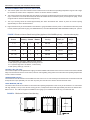
Eight call buttons may be accomodated on the standard 1 gang VM-300/4T entrance panel. If a PO-202I Post Office lock panel
is used, minimum panel size is 2 gang. For additional buttons, consult the ENTRANCE PANEL HOUSING CHART (FIG. 1) below.
FIGURE 1 - Entrance Camera Panel Housing Chart (Applies to VAN-GUARD style only — ask about other styles)
Number of
Buttons
No. of modules
Directory Camera Button
1-8
1.
2.
3.
4.
Flush
Housing
Wall Opening
Width (A)*
Wall Opening
Height
1/2
1
1/2
BB-102
8-1/4"
10-1/4"
12 - 28
1
1
1
BB-103
12-1/4"
10-1/4"
32 - 60
1
1
1
BB-203
12-1/4"
16-1/4"
64 - 120
2
1
2
BB-205
20-1/4"
16-1/4"
124 - 136
3
1
2
BB-206
24-1/4"
16-1/4"
For postal option (PO-202I), additional panel required.
Wall opening height of BB-200 series housing is 16-1/4".
For systems larger than 136 buttons, contact factory.
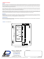
Wall opening width (A)*, see FIG. 2.
CONTROL UNIT (PK-314A) :
The Control Unit (PK-314A Amplifier/Power Supply) should be installed inside the Entrance Panel. If the Control Unit must be installed
away from the Entrance Panel for some reason, observe notes regarding wiring and do not locate where the operating temperatures
of 0-40 C will be exceeded.
TRANSFORMER (PS-250) :
The transformer must be located in an accessible area near a source of 117 VAC and away from extreme heat. The transformer should
be kept at least 3' (but preferably not more than 50') away from the PK-314A. Observe all local electrical codes.
VIDEO MONITOR (VM-104) :
The video monitor must not be located in an area where the operating temperature of 0-40 C may be exceeded or in an environment
with high humidity. The top of the VM-104 housing (IH-357, IH-358) should be located approximately 66" above the finished floor.
Refer to FIG. 3 and VM-104 equipment installation notes (page 7) for installation of IH-357 ring or IH-358 back box.
FIGURE 2 - BB-Series Entrance Panel Housing
16 1/4"
16 1/4"
16 1/4"