1
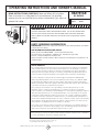
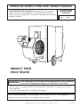
Operating Instructions and Owner’s Manual heatstar BY eNERCO models READ INSTRUCTIONS CAREFULLY: Read and follow all instructions. Place instructions in a safe place for future reference. Do not allow anyone who has not read these instructions to assemble, light, adjust or operate the heater. 4000ID 7000ID INDIRECT FIRED Space HEATER the information in this manual is not followed exactly, a fire or explosion WARNING: Ifmay result causing property damage, personal injury or loss of life. — Do not store or use gasoline or other flammable vapors and liquids in the vicinity of this or any other appliance. —Service must be performed by a qualified service agency. This is a vented space heater. It uses air (oxygen) from the area in which it is used. Adequate combustion air and ventilation must be provided. Refer to page 5. ENERCO GROUP, INC., 4560 W. 160TH ST., CLEVELAND, OHIO 44135 • 800-251-0001 08/08 # xxxxx WARNING: WARNING: YOUR SAFETY IS IMPORTANT TO YOU AND TO OTHERS, SO PLEASE READ THESE INSTRUCTIONS BEFORE YOU OPERATE THIS HEATER. NOT FOR HOME OR RECREATIONAL VEHICLE USE WARNING: GENERAL HAZARD WARNING: FIRE, BURN, INHALATION, AND EXPLOSION HAZARD. KEEP SOLID COMBUSTIBLES, SUCH AS BUILDING MATERIALS, PAPER OR CARDBOARD, A SAFE DISTANCE AWAY FROM THE HEATER AS RECOMMENDED BY THE INSTRUCTIONS NEVER USE THE HEATER IN SPACES WHICH DO OR MAY CONTAIN VOLATILE OR AIRBORNE COMBUSTIBLES, OR PRODUCTS SUCH AS GASOLINE, SOLVENTS, PAINT THINNER, DUST PARTICLES OR UNKNOWN CHEMICALS. FAILURE TO COMPLY WITH THE PRECAUTIONS AND INSTRUCTIONS PROVIDED WITH THIS HEATER, CAN RESULT IN DEATH, SERIOUS BODILY INJURY AND PROPERTY LOSS OR DAMAGE FROM HAZARDS OF FIRE, EXPLOSION, BURN, ASPHYXIATION, CARBON MONOXIDE POISONING, AND/OR ELECTRICAL SHOCK. ONLY PERSONS WHO CAN UNDERSTAND AND FOLLOW THE INSTRUCTIONS SHOULD USE OR SERVICE THIS HEATER. IF YOU NEED ASSISTANCE OR HEATER INFORMATION SUCH AS AN INSTRUCTIONS MANUAL, LABELS, ETC. CONTACT THE MANUFACTURER. WARNING: The State of California requires the following warning: COMBUSTION BY-PRODUCTS PRODUCED WHEN USING THIS PRODUCT CONTAIN CARBON MONOXIDE, A CHEMICAL KNOWN TO THE STATE OF CALIFORNIA TO CAUSE CANCER AND BIRTH DEFECTS (OR OTHER REPRODUCTIVE HARM). Contents WARNING: WARNINGS................................................................................... 2 READ THE INSTRUCTIONS GIVEN IN THIS MANUAL BEFORE USING THE APPLIANCE. SPECIFICATIONS............................................................................ 3 • DO NOT USE GASOLINE, NAPHTHA OR VOLATILE FUELS. instruction for use................................................................. 5 installation.............................................................................. 4 Ventilation................................................................................ 5 • THE ELECTRICAL SYSTEM TO WHICH THE APPLIANCE IS CONNECTED MUST COMPLY WITH ALL SAFETY REGULATIONS IN FORCE. A RESIDUAL CURRENT CIRCUIT BREAKER MUST BE PROVIDED ON THE MAIN DISTRIBUTION BOARD. MAINTENANCE............................................................................. 6 TROUBLESHOOTING..................................................................... 7 wiring diagrams...................................................................... 8 parts list...................................................................................12 • UNPLUG THE HEATER BEFORE ATTEMPTING ANY SERVICE OR MAINTENANCE. • ALWAYS CHECK THE POWER SUPPLY CABLE BEFORE USE. IT MUST NOT BE BENT, CRUSHED, OR ANYWAY DAMAGED. • THE POWER SUPPLY CABLE MUST BE REPLACED ONLY BY QUALIFIED PERSONNEL. • ONLY USE AN ORIGINAL H07RN-F POWER CABLE WITH WATERPROOF PLUG. • DO NOT TOUCH THE EXHAUST GAS OUTLET. DANGER OF BURNS! ENERCO GROUP, INC. |Indirect Fired Portable Heater 2 Operating Instructions and Owner’s Manual • All fire prevention regulations must be adhered to. • The room or building which is being heated must be sufficiently ventilated so that the heater has enough air to function properly. • The heater must be near a chimney or chimney flue and a suitable electric switchboard. • Don’t let animals or children near the heater. • Make sure heater is inspected before each use, and at least annually by a qualified service person. • After use make sure the disconnecting switch is off. When using any type of space heater it is obligatory: not to exceed the maximum level of heat output of the furnace (“TECHNICAL SPECIFICATIONS TABLE”). • To make sure that there is adequate air circulation and air supply to the heater and that nothing is obstructing the aspiration and expulsion of air; movement of air may be obstructed in various ways including placing covers or other objects on the heater or positioning the heater too near a wall or other large object. If the airflow is not adequate, the combustion chamber will overheat and the overheat safety thermostat L1 will turn the burner off and on continuously (“troubleshooting”). Important Before using the heater, read and understand all instructions and follow them carefully. The manufacturer is not responsible for damages to goods or persons due to improper use of units. General Recommendations The heater is designed and approved for use as a construction heater in accordance with Standard ANSI Z83.7 - CGA 2.14. Intended use is the temporary heating of buildings or structures under construction, alteration or repair. Warning CHECK WITH YOUR LOCAL FIRE SAFETY AUTHORITY IF YOU HAVE QUESTIONS ABOUT APPLICATIONS. Here are a few general guidelines which should be followed: • Follow the instructions in this booklet very carefully. • Don’t install the heater in places where there may be a risk of fire or explosion. • Inflammable material should be kept at a safe distance from the heater (Minimum 6 feet). TECHNICAL SPECIFICATIONS Heat input Air flow 4000ID 4000ID 7000id hd7000id [kBTU/h] 400 400 700 700 [cfm] 4.240 4.240 7.420 7.420 [kBTU/h] 340 340 595 595 Oil N”2 Max fuel consumption [LBH] 20.4 20.4 35.8 35.8 Natural gas fuel consumption [CFH] 391.4 391.4 684.9 684.9 Propane fuel consumption [CFH] 157.0 157.0 274.7 274.7 1 1 1 1 Voltage [V] 120 220 220 220 Frequency [Hz] 60 60 60 60 [W] 1.240 1.760 2.120 2.300 [A] 13.5 14.5/5.8 7.0 14.8 [USgalll1] 2.25 GPH 600 B 2.25 GPH 60’ B 3.50 GPH 60’ B Heat output Phase Power supply Electric consumption Diesel burner model Riello 40 F10 Nozzle Gas burner model (nalural gas or propane) Riello 40 F15 3.50 GPH 60’ B Riello 40 G400 Riello 40 G750 Gas supply pressure: natural gas min 4” w.c. max 10” w.c. min 7” w.c. max 14” w.c. Gas supply pressure: propane min 8” w.c. max 13” w.c. min 8” w.c max 14” w.c. Static pressure [lnWC] 0.4 0.8 0.4 0.8 Flue diameter [In] 5.9 5.9 7.9 7.9 [lnWC] 0.05 0.05 0.05 0.05 Compulsory flue draft Maximum air temperature °F 250.0 250.0 250.0 250.0 Dimensions. L x W x H [In] 72x31x43 82x31x43 85x35x53 101x35x53 Weight [Ib] 353 364 550 562 832 (HD Version) ENERCO GROUP, INC. |Indirect Fired Portable Heater 3 Operating Instructions and Owner’s Manual Control Board INSTALLATION Warning The following operations must be carried out by qualified personnel only. Electrical Connections Settings Every space heater is supplied along with the safety and control devices which are indispensable to the correct functioning of the unit. The electric switchboard, burner, the fan thermostat, overheat safety thermostat and the overheat thermostat with manual restart have already been connected. Warning Power supply cord of proper dimension shall be connected to the main switchboard and heater shall be grounded. Electrical grounding shall be in compliance with the National Electrical Code ANSI/NFPA 70 or the CSA C22.1 Canadian Electrical Code, Part I. The following operations must now be carried out: • Plug in the power cord having read the adhesive label which details electricity supply characteristics. • The burner must be connected to the fuel supply (Burner Instruction Manual). • Connect the burner to the electricity supply with the burner plug. • Connect accessories such as the room thermostat or clock to the unit’s electric switchboard with the thermostat plug. Having completed all these operations check carefully that all electrical connections correspond to the wiring diagram. When the heater is first turned on you must check that the fan does not use more current than the maximum permitted limit. Finally, to regulate the burner, follow the instructions in the Burner Instruction Manual. INSTRUCTIONS FOR USE Switching On • Set the control knob (2) in position “0”. • Turn on the disconnecting switch on the electric switchboard. • If the unit is operated manually turn the control knob to . The burner starts up, the combustion chamber heats up and then the fan starts. • If the unit operates automatically set the room thermostat at the desired level and turn the control knob (2) to : the heater will now start and stop automatically. • If the heater doesn’t start after you have completed the above operations consult the Troubleshooting section of this manual. 1 control lamp 2 control knob heat - stop - ventilation only 3 power cord fastener 4 overheat safety thermostat, l1 5 fan thermostat, f 6 limit thermostat with manual restart, l2 7 Thermostat reset switch 8 hour counter 9 overheat thermostats control lamp, l1, l2 10 Fan stop control lamp 11 heated diesel filter plug Turning Off 12 burner plug In manual operation turn control knob (2) to “0” or turn off control in automatic operation. 13 room thermostat plug The burner stops while the fan turns itself on and off until the combustion chamber has completely cooled down. ENERCO GROUP, INC. |Indirect Fired Portable Heater 4 Operating Instructions and Owner’s Manual Ventilation MAINTENANCE The space heater provides heat by releasing and dispersing hot air. An air head is supplied with each unit but it can be replaced by other types of head with two or four openings which allow for flexible tubes in heat distribution. The screws which hold the original outlet in place should be removed and the new outlet should be screwed on in place of the old. Warning The following operations must be carried out by qualified personnel only. Before carrying out any maintenance operation the heater must be disconnected from the mains. Therefore: The new head may be connected to new air ducts if the user wishes to satisfy specific needs. In this case and in particular if the diameter and length of the ducts have been changed or if the number of bends has been modified, air output may vary. Consequently it is very important to check and regulate air output when any modification is made to air heads or air ducts. In all circumstances you must ensure that: • The fan motor does not absorb more current than the maximum permitted limit; • The volume of air flow corresponds to the recommended level. If the heater is equipped with centrifugal fan and if the volume of hot air differs from preset values proceed as follows (Fig. 1): • Stop the machine as instructed above • Turn off the disconnecting switch on the electric switchboard. • Wait until the heater has cooled. Cleaning the Heat Exchanger and the Combustion Chamber For the heater to operate efficiently the heat exchanger and combustion chamber must be cleaned after a period of prolonged use and more frequently if too much soot builds up. Soot builds up when there is not enough chimney draft, when the fuel is of very poor quality, when the burner is regulated incorrectly or when the heater is switched on and off too frequently. If the heater starts vibrating when it is turned on there is probably too much soot. To get at the heat exchanger (1) take off the front panel (3) and then remove the smoke box panel (2) and remove baffle plates (7). To get at the combustion chamber (4) remove the burner (5). Fig. 1 1 4 3 Cleaning the Fan Remove any dirt or extraneous material from the mesh of the aspiration grill (6) and if necessary clean the propeller with an air-suction tool. 2 1 7 3 2 6 1) Remove the aspiration grill which is on fan motor side of the unit. 2) Remove the screws (2) from the motor slide. 3) Remove the belt (1). 4) Loosen the bolts (3). 5) Turn the pulley clockwise and anti-clockwise in order to increase or reduce the volume of air. 6) Tighten the bolts (3). 7) Put back the aspirations grill 8) Repeat operations from (1) to (7) until the correct volume of air flow has been achieved. 5 4 Fig. 3 Cleaning the Burner For the heater to work efficiently the burner must be serviced regularly by an Authorized Service Technician. All cleaning, servicing and regulation operations must be carried out as indicated in the Burner Instruction Manual. Draft The evacuation smoke flues shall be made with steel. Efficient combustion and trouble-free working of the burner depend on efficient flue draft. The unit must be connected to the chimney flue in accordance with current legal regulations and in line with the following guidelines: • The tube which carries the smoke should cover as short a distance as possible and should slant upwards. • There should be no sharp bends in the tubes and the diameter of the tubes must never be reduced. • Every heater must have its own chimney. • Flue draft must at least correspond to the minimum compulsory level in the Technical Specifications. ENERCO GROUP, INC. |Indirect Fired Portable Heater Warning After every type of technical maintenance, please verify that the machine starting regularly. 5 Operating Instructions and Owner’s Manual any propane gas container. Propane gas cylinder shall be in compliance with national standards and shall be arranged to provide for vapor withdrawal from the operating cylinder. TRANSPORTING AND MOVING THE HEATER To move the Jumbo use the front handles and back wheels. The gas shall be turned off at the propane supply cylinder when the heater is not in use. Visually inspect hose assembly prior to each use of the heater. If it is evident there is excessive abrasion or wear, or the hose is cut, it must be replaced prior to the heater being put into operation. After installation, proper instruments or devices shall be used to check and avoid any gas leakage. Gas leakage testing shall be regularly operated. Warning Before moving the unit: • Turn it off as indicated above. • Disconnect electricity by pulling out the plug. Regulation of Combustion - I° Operation Suitable equipment must always be used when moving a unit and the instructions given above must be scrupulously adhered to. After having checked the hermetic seal and of combustion waste products line, heater may be operated for the first time. Warning To perform regulation of combustion correctly, combustion waste products must be analyzed using appropriate instruments: values recommended by actual standards must be reached. Never try to lift the heater manually. Doing so could result in physical injury. The regulation procedure has been on the Burner Instruction Manual; final values of CO2 shall be correspondent to excess air factor of 1.2 (12.5 for gas-oil, 9.7% for G20. 9.6% for G25. 11.7% for G30 and 11.7% for G31) while CO level shall be less than 75 ppm. If heater is connected to propane supply cylinder and it is to be stored indoors, the connection between the propane cylinder and the heater must be disconnected and the cylinder removed from the heater and stored in accordance with Standard for the Storage and Handling of Liquefied Petroleum Gases, ANSI/NFPA 58 and CSA B149.1, Natural gas and Propane Installation Code. Warning Analysis of Combustion Waste Products Never stop the heater by simply turning off the disconnecting switch on the electric switchboard. The electrical supply must only be disconnected when the fan has come to a complete stop. The probes which check the composition of combustion waste products and smoke temperature must be positioned as indicated in Fig. 2. When these tests have been completed the hole which was drilled for the probe must be sealed with a material which is resistant to high temperatures and which ensures that the tube remains airtight. When the control knob is turned to the symbol operates in continuous fan mode. 8 in mm 200 Fig. 2 Connection to Fuel Supply To connect the burner to the fuel supply follow the instructions in the Burner Instruction Manual. The gas burner can use both methane gas or propane. Burners are predisposed at factory to be used with natural gas. If propane shall be used, burners shall be adapted according to the instruction manual of the burner. In case of connection of heater to natural gas,the installation shall conform with local codes, or, in the absence of local code, with the National Fuel Gas Code ANSI Z223.1/NFPA and the Natural Gas and Propane Installation Code, CSA B149.1. In case of connection of heater to propane supply cylinder, the installation shall conform with local codes or, in the absence of local code, with tyhe Standard for the Storage and Handling of Liquefied Petroleum Gases, ANSI/FNPA 548 and the Natural Gas and Propane Installation Code, CSA B149.1. Heater must be located at least 6 ft in the U.S. or 10 ft in Canada from ENERCO GROUP, INC. |Indirect Fired Portable Heater 6 Operating Instructions and Owner’s Manual the heater Troubleshooting Trouble Cause Solution • Check function and positioning of main switch • Check power cord • Faulty electrical supply • Check electrical connections • Check fuses • Wrong positioning of main switch • The heater won’t start • Put main switch in correct position • Check setting of room thermostat • Wrong setting of room thermostat • Check function of room thermostat • Safety device (burner, thermostat L2, fan thermal relay) not restarted after repairs • Press the appropriate restart button: burner (button on control device) thermostat (button (6) fan thermal relay (button (11) • Check fuel flow • Thermostat L1 cuts in (the lamp (9) light up and then it cuts down) • The combustion chamber has overheated • Check position registers, draw - holes, etc. • Remove extraneous material from air ducts and ventilation grills • Thermostat L2 cuts in (Warning lamp (9) lights up) • Excessive combustion chamber over heating • Check as indicated above • If fault persists contact our Service Center • Heater with helicoidal ventilator: remove eventual debris preventing free flow of air on intake and outlet. Check length of air ducts, reduce if excessive. • Thermal relay RM cuts in (Warning light (10) lights up) • Fan motor current absorption is excessive • Heater with centrifugal ventilator: check setting of transmission belt as indicated in chapter (“CONNECTION TO HOT AIR DUCTS”). • Always check that current absorption remains below value indicated on motor manufacturer plate • The burner starts up, the flame doesn’t light up and the restart light on the control device comes on • Burner not working correctly • Press the restart button to turn on the heater. If the same problem arises again call an Authorized Service Technician • Check fuses • No electrical power • Check electrical connections • F thermostat out of order • Check the thermostat, set it and replace it if necessary • Winding of motor burnt or interrupted • Replace the fan motor • Condenser burnt (mod. “M”) • Replace the condenser • Motor bearings blocked • Replace the bearings • Extraneous material on fan blades • Remove extraneous material • Not enough air circulation • Remove obstacles to air circulation • Wrong burner • Call an Authorized Service Technician • The fan doesn’t start up or starts up late • The fan vibrates or makes unusual noise • Not enough heat ENERCO GROUP, INC. |Indirect Fired Portable Heater 7 Operating Instructions and Owner’s Manual Wiring Diagram 4000iD Series Models Drawing Legend m Fan Motor ta Room Thermostat f Fan Thermostat fb Burner Fuse 6 A l1 Overheat Safety Thermostat st Control Lamp l2 Limit Thermostat with Manual Restart sl Overheat Thermostats Control Lamp rv Control Knob | Ventilation Only rf Heated Filter br Burner ENERCO GROUP, INC. |Indirect Fired Portable Heater 8 Operating Instructions and Owner’s Manual Wiring Diagram 4000iD and 7000iD Series Models Drawing Legend ts Fans Thermal Relay sb Fan Stop Control Lamp tm Fans Tele-contactor pb Steckdose Burner Plug c Condenser Motor co Hour-Counter pa Room Thermostat Plug pf Heated Filter Plug re Relay 220V/60Hz rf Heated Filter ENERCO GROUP, INC. |Indirect Fired Portable Heater 9 Operating Instructions and Owner’s Manual 4000ID and 7000ID Series Indirect-Fired Space Heater 17 09 04 06 40 05 A 23 19 03 10 38 26 39 22 21 30 20 31 29 16 25 28 8 46 32 27 26 15 07 18 24 91 10 12 09 A 45 03 02 11 01 41 42 43 44 ENERCO GROUP, INC. |Indirect Fired Portable Heater 10 Operating Instructions and Owner’s Manual 4000ID and 7000ID Series Indirect-Fired Space Heater 56 58 47 50 59 48 64 49 54 57 62 63 48 55 60 56 52 61 51 65 53 64 41 68 67 69 80 70 81 66 71 78 79 83 82 72 75 74 76 77 89 90 107 96 65 84 73 88 91 R 95 85 105 94 101 98 103 100 106 104 93 101 102 99 R 87 97 86 92 Operating Instructions and Owner’s Manual 11 ENERCO GROUP, INC. |Indirect Fired Portable Heater 4000ID/7000ID Series Indirect-Fired Space Heater Parts List no. Stock No. 4000 G01098 • 7000 Description 01 no. Burner support T10602 • Burner plate seal 21 Ox21 Ox5 • G04017-9010 G04174-9010 • Vertical back SX angle steel G01852-9010 • • 25 Vertical back OX angle steel G01746-9010 • • Outlet air panel G04175-9010 G04183-9010 • • Front upper panel G01086-9010 • 26 Lower short angle steel G04184-9010 05 G01826 • G01744-9010 • 04 G01819-9010 Vertical front OX angle steel G01835-9010 Burner panel G04018-9010 • 7000 Description 24 Burner plate seal 250x250x5 • 03 G01834-9010 G01742-9010 02 T10634 4000 23 • G01653 Stock No. G01829-9010 • • • 27 Lower long SX angle steel G01750-9010 • 06 • Inner front upper panel G01235 G01830-9010 • • 28 G01818-9010 • Lower long OX angle steel G01752-9010 07 • Rear upper panel G01716-9001 G01825 • G01822 • 29 • Comb. chamber support • G01754 08 Inner rear upper panel • G01718 G01816-9010 G04185 • 30 • Comb. chamber SX support • G01756 09 Side panel G01720-9010 G01824 • G04186 • 31 • Comb. chamber OX support • G01758 10 Inner side panel G01722 G01814-9010 • • Chimney flange 0150 32 U10101-9010 • • Aluminum joint 38 M20111 • • Washer 12’26x12’44x4 C10535 • 11 G01687-9010 G01813-9010 • Wheel 12’ 300 - 12’ 25 39 • C10545 12 • Wheel 12’ 400 - 12’ 25 Chimney panel G01724-9010 G01821 • • 14 40 M20202 • • Wheel holder 41 02AC550 • • Kit Oil pre-heaters filter 1/4” 42 T20241 • • OR KIToil filter 43 T20242 • • Filter cartridge 44 898012 • • Hoses 45 G04187-9010 • • Flask G04180-3001 • Motor support plate G01728 G01817-9010 • • 15 Bottom panel G01730-9010 G04179-9010 • • 16 Wheel axle G01732-9010 G04039-9010 • 46 • Upper back short angle steel G04181-3001 17 • Front support G01692-9010 18 Chimney flange 0200 • U10103-9010 • G01832-9010 • G04048-9010 • 47 19 Handle G04050-9010 Aluminum joint • 48 C30328 • • Plug 49 M20418 • • Wing nut lock G04189-9010 • Upper front short angle steel G01734-9010 G01831-9010 • • 20 Upper long SX angle steel G01736-9010 G01831-9010 50 • • G04192-9010 21 Upper long OX angle steel G01738-9010 G01833-9010 • • 51 • Flap door G04193-9010 • G04195-9010 22 Vertical front SX angle steel G01740-9010 Casing front panel G04190-9010 • 52 • ENERCO GROUP, INC. |Indirect Fired Portable Heater • Burner casing top cover G04196-9010 12 • Operating Instructions and Owner’s Manual 4000ID/7000ID Series Indirect-Fired Space Heater Parts List no. Stock No. 4000 G04198-9010 • 7000 Description 53 no. G04201-9010 88 • Tank casing lower panel • Chimney cover • 125001 • G04208 • G00218 • • EI. control box 57 E20719-02 • • Electrical components box • • 90 Reinforced frame G01767-9010 58 P30159 • • Bulbs holder 59 C30712 • • Clip G04212-9010 • • 91 Fan panel G01769-9010 60 E50748 • • Thermostat TY95 30/90 °C Campini 61 E50749 • • Thermostat TY95H 120°C Campini P30143 • • 92 Protection grille • P30140 62 E50747 • • Thermostat TY95 0/60 °C Campini 63 E50750 • • Safety thermostat plastic profile 64 C30343 • • Cable protection 12’19 G00220 • E10682-220 • Motor HP 2 220/60 mono 93 E10683-220 C10931 • • Motor HP 3 220/60 mono Sheave 0105 Var. 024 94 65 C10929 EI. control box • C10912 • • Sheave 0105 Var. 028 Sheave 0160 1B 025 95 • 66 • C10904 Electrical components box E20712 Female plug 1” Centrifuge air fan G04211-9010 E20712 • 89 56 Chimney sea 551x248x5 • G04209 G00222 Chimney seal 438x248x5 • G01760 • 55 7000 Description 87 Burner casing DX cover G04205-9010 • G01849 • 54 G04204-9010 T10659 T10635 • G04202-9010 4000 86 Burner casing SX cover G04199-9010 Stock No. • P30142 Sheave 0200 1B 025 • 96 Protection grille 67 E20949 • • Cable fastener PG 13,5 68 E20950 • • Ring nut PG13,5 69 E10419 • • Contactor Wimex KN16-10 V230 70 G04042 • • Plate for electrical components 71 E20301 • • Terminal board 12 el. mmq 10 72 G04041 • • Hour-counter support plate 73 DR205 • • Hour-counter 100 G01998 • • Motor support plate 74 E10109 • • Control knob 101 M10234 • • Screw TE M12x55 75 E11021 • • Red pilot lamp 12’12 V230 102 M10714 • • NutM12 76 E20626 • • Thermostat plug 3P + T M10234 • 77 E20627 • • Plate plug 3P + T 78 E20629 • • Thermostat plug 4P + T G00216 • C30401 • E11235 • • E11236 Capacitor 25 ~F G02000 • Mounting plate on fan case G02001 • Screw TE M12x55 103 M10221 G04213-9005 • • Relay Finder 65.31 AC 81 G04207 • • Relay flange 82 E20639 • • Thermostat plug 4P + T 83 E20665 • • Drain plug G01810 • 84 Screw TE M12x70 • Crankcase G04214-9005 C10917 • Capacitor 50 ~F • 99 • E11120 Seal3x15 98 Plate plug 4P + T 80 • • Belt B43 105 C10923 AN006-1 • • Belt B50 Fan AT 12/12 106 AN007-1 107 E20712 • • Fan AT 15/15 • EI. components box 80x80 Combustion chamber • G01773 85 97 104 79 G00217 • P30141 G01759 • • Baffle plate ENERCO GROUP, INC. |Indirect Fired Portable Heater 13 Operating Instructions and Owner’s Manual Operating Instructions and Owner’s Manual heatstar BY eNERCO models READ INSTRUCTIONS CAREFULLY: Read and follow all instructions. Place instructions in a safe place for future reference. Do not allow anyone who has not read these instructions to assemble, light, adjust or operate the heater. 4000ID 7000ID WARNING: USE ONLY MANUFACTURER’S REPLACEMENT PARTS. USE OF ANY OTHER PARTS COULD CAUSE INJURY OR DEATH. REPLACEMENT PARTS ARE ONLY AVAILABLE DIRECT FROM THE FACTORY AND MUST BE INSTALLED BY A QUALIFIED SERVICE AGENCY. PARTS ORDERING INFORMATION: PURCHASING: Accessories may be purchased at any Mr. Heater/HeatStar local dealer or direct from the factory FOR INFORMATION REGARDING SERVICE Please call Toll-Free 800-251-0001 • www.enerco-mrheater.com Our office hours are 8:30 AM – 5:00 PM, EST, Monday through Friday. Email to: [email protected] Please include the model number, date of purchase, and description of problem in all communication. LIMITED WARRANTY The company warrants this product to be free from imperfections in material or workmanship, under normal and proper use in accordance with instructions of The Company, for a period of one year from the date of delivery to the buyer. The Company, at its option, will repair or replace products returned by the buyer to the factory, transportation prepaid within said one year period and found by the Company to have imperfections in material or workmanship. If a part is damaged or missing, call our Technical Support Department at 800-251-0001. Address any Warranty Claims to the Service Department, Enerco Group, Inc., 4560 W. 160TH ST., Cleveland, Ohio 44135. Include your name, address and telephone number and include details concerning the claim. Also, supply us with the purchase date and the name and address of the dealer from whom you purchased our product. The foregoing is the full extent of the responsibility of the Company. There are no other warranties, express or implied. Specifically there is no warranty of fitness for a particular purpose and there is no warranty of merchantability. In no event shall the Company be liable for delay caused by imperfections, for consequential damages, or for any charges of the expense of any nature incurred without its written consent. The cost of repair or replacement shall be the exclusive remedy for any breach of warranty. There is no warranty against infringement of the like and no implied warranty arising from course of dealing or usage of trade. This warranty will not apply to any product which has been repaired or altered outside of the factory in any respect which in our judgment affects its condition or operation. Some states do not allow the exclusion or limitation of incidental or consequential damages, so the above limitation or exclusion may not apply to you. This Warranty gives you specific legal rights, and you may have other rights which vary from state to state. Enerco Group, Inc. reserves the right to make changes at any time, without notice or obligation, in colors, specifications, accessories, materials and models. ENERCO GROUP, INC., 4560 W. 160TH ST., CLEVELAND, OHIO 44135 • 800-251-0001 Mr. Heater is a registered trademark of Enerco Group, Inc. © 2004, ENERCO GROUP, INC. All rights reserved ENERCO GROUP, INC. |Indirect Fired Portable Heater 14 Operating Instructions and Owner’s Manual 08/08 # xxxxx GUIDE D'UTILISATION ET INSTRUCTIONS DE FONCTIONNEMENT MODÈLES LISEZ SOIGNEUSEMENT LES INSTRUCTIONS. Lisez et observez toutes les instructions. Conservez les instructions pour vous y référer ultérieurement. Interdisez à quiconque n'ayant pas lu les présentes instructions d'assembler, d'allumer, de régler ou de faire fonctionner cet appareil de chauffage. HEATSTAR D'ENERCO 4000ID 7000ID AVERTISSEMENT : N'UTILISEZ QUE LES PIÈCES DE REMPLACEMENT DU FABRICANT. L'UTILISATION D'AUTRES PIÈCES RISQUE DE CAUSER DES BLESSURES OU LA MORT. LES PIÈCES DE REMPLACEMENT NE SONT OFFERTES QUE PAR LE FABRICANT ET DOIVENT ÊTRE INSTALLÉES PAR UNE ENTREPRISE SPÉCIALISÉE. INFORMATIONS SUR LA COMMANDE DE PIÈCES : ACHAT : on peut se procurer des accessoires auprès de tous les détaillants locaux Mr. Heater/HeatStar ou directement du fabricant POUR OBTENIR DES INFORMATIONS SUR LE SERVICE Appelez sans frais au 800-251-0001 • www.enerco-mrheater.com Nos heures d'ouverture sont de 8 h 30 à 17 h HNE, du lundi au vendredi. Adressez vos courriels à : [email protected] Veuillez indiquer le numéro du modèle, la date d'achat et la description du problème dans toutes vos communications avec nous. GARANTIE LIMITÉE L'entreprise garantit ce produit contre tout défaut de matériel ou de main-d'œuvre, dans des conditions d'utilisation normales et adéquates, conformément aux instructions de l'entreprise, pour une période de un an à compter de la date de livraison à l'acheteur. L'entreprise réparera ou remplacera, à sa discrétion, les produits retournés port payé par l'acheteur au fabricant dans la période de un an et jugés par l'entreprise comme présentant des défauts de matériel ou de main-d'œuvre. Si une pièce est endommagée ou manquante, composez le 1 800 251-0001. Adressez toute réclamation relative à la garantie à Service Department, Enerco Group, Inc., 4560 W. 160TH ST., Cleveland, Ohio 44135 États-Unis. Indiquez vos nom, adresse et numéro de téléphone ainsi que les détails de la réclamation. Indiquez-nous également la date d'achat et le nom et l'adresse du détaillant de qui vous avez acheté le produit. Ce qui est énoncé ci-dessus constitue la responsabilité totale de l'entreprise. Il n'existe aucune autre garantie, expresse ou tacite. Plus précisément, il n'y a aucune garantie concernant l'adéquation à une utilisation particulière ni aucune garantie concernant la qualité marchande. En aucun cas l'entreprise ne sera tenue responsable des retards causés par des défectuosités, ni des dommages indirects, ni des dépenses encourues sans son consentement écrit, quelle que soit leur nature. Le coût de la réparation ou du remplacement sera le seul recours possible en cas de violation de garantie. Il n'y a aucune garantie contre une transgression de ce genre ni aucune garantie tacite découlant des usages du commerce ou de la façon habituelle d'échanger. La présente garantie ne s'applique à aucun produit qui a été réparé ou modifié par d'autres que le fabricant si cela influe de quelque façon que ce soit sur l'état de l'appareil ou son fonctionnement, selon notre jugement. Certains États ou provinces ne permettent pas d'exclure ou de limiter les dommages indirects ou subséquents. Par conséquent, les limitations ou exclusions ci-dessus mentionnées ne vous concernent peut-être pas. La présente garantie vous accorde des droits juridiques précis, mais vous pourriez avoir d'autres droits qui varient selon la province ou l'État. Enerco Group Inc. se réserve le droit d'effectuer des modifications en tout temps, sans préavis ni obligation, aux couleurs, aux spécifications, aux accessoires, aux matériaux et aux modèles. ENERCO GROUP, INC., 4560 W. 160TH ST., CLEVELAND, OHIO 44135 USA • (800) 251-0001 Mr. Heater est une marque déposée d'Enerco Group Inc. © Enerco Group, Inc., 2004. Tous droits réservés. ENERCO GROUP, INC. |Générateur d'air chaud portable à combustion indirecte 14 Guide d'utilisation et instructions de fonctionnement 08/08 Nº xxxxx Liste de pièces des générateurs d'air chaud portables à combustion indirecte, modèles 4000ID et 7000ID Nº Nº DE G04198-9010 4000 • 53 G04199-9010 G04201-9010 7000 DESCRIPTION • • COUVERCLE GAUCHE DE CAISSON DU BRÛLEUR 85 Nº 4000 Nº DE • G01759 T10659 COUVERCLE DROIT DE CAISSON DU BRÛLEUR G01849 • • C30343 64 • E50750 63 • E50747 62 • E50749 61 • E50748 60 • C30712 59 • P30159 58 • E20719-02 57 • G00218 56 • PANNEAU INFÉRIEUR DE CAISSON DE RÉSERVOIR BOÎTIER DE COMMANDE 88 • E10109 74 • DR205 73 • G04041 72 • E20301 71 • G04042 70 • E10419 69 • E20950 68 • E20949 67 • • • • • • • • • • • • • DÉFLECTEUR BOUCHON 1 PO CHÂSSIS RENFORCÉ G01767-9010 • PANNEAU DE VENTILATEUR G01769-9010 • GRILLE DE PROTECTION P30140 • • E10683-220 • E11021 75 • E11120 80 • • • 90 • 91 • 92 E10682-220 MOTEUR 2 HP 220/60 MONOPHASÉ 93 • C10929 • E20626 76 • G04207 81 • JOINT ISOLANT DE CHEMINÉE 438 X 248 X 5 • • VENTILATEUR CENTRIFUGE • BOÎTIER ÉLECTRIQUE PORTE-BULBES COLLIER THERMOSTAT TY95 30/90 °C CAMPINI THERMOSTAT TY95H 120 °C CAMPINI THERMOSTAT TY95 0/60 °C CAMPINI PROTECTION POUR THERMOSTAT DE PROTECTION PLASTIQUE 12’ 19 • MOTEUR 3 HP 220/60 MONOPHASÉ RÉA 0105 VAR. 024 94 • BOÎTIER ÉLECTRIQUE • E20627 77 • C10912 • • C10904 P30142 • RÉA 0105 VAR. 028 RÉA 0200 1B 025 • 96 GRILLE DE PROTECTION P30141 97 • • E11235 • C30401 • JOINT 3 X 15 CONDENSATEUR 25 ~F 98 E11236 G02000 • • 99 G02001 • • M10714 102 • M10234 101 • G01998 100 • • • CONDENSATEUR 50 ~F PLAQUE DE MONTAGE DE BOÎTIER DE VENTILATEUR PLAQUE DE SUPPORT DE MOTEUR VIS TE M12 X 55 ÉCROU M12 VIS TE M12 X 55 103 M10221 G04213-9005 • VIS TE M12 X 70 • 104 CARTER G04214-9005 RELAIS FINDER 65.31 AC BRIDE DE RELAIS C10917 • • COURROIE B43 105 C10923 FICHE DE THERMOSTAT 4P + T BOUCHON DE DRAIN RÉA 0160 1B 025 95 PRESSE-ÉTOUPE PG 13,5 ÉCROU À ŒILLET PG 13,5 CONTACTEUR WIMEX KN16-10 V230 PLAQUE DE COMPOSANTES ÉLECTRIQUES BARRETTE DE CONNEXION 12 EL. MMQ 10 PLAQUE DE SUPPORT DE COMPTEUR COMPTEUR D'HEURES COMMUTATEUR LAMPE TÉMOIN ROUGE 12’ 12 V230 FICHE DE THERMOSTAT 3P + T • M10234 PLAQUE DE PRISE 3P + T FICHE DE THERMOSTAT 4P + T • • E20639 82 • JOINT ISOLANT DE CHEMINÉE 551 X 248 X 5 COUVERCLE DE CHEMINÉE 125001 • 89 G04209 • G04211-9010 • • G04212-9010 • • P30143 • • • C10931 BOÎTIER DE COMMANDE G00222 • • • E20629 78 PLAQUE DE PRISE 4P + T G00217 • E20665 83 CHAMBRE DE COMBUSTION G01773 7000 DESCRIPTION • • • 87 G01760 • G04205-9010 86 T10635 • 54 G04202-9010 G04204-9010 55 G04208 • G00220 65 E20712 66 E20712 • G00216 79 • G01810 84 AN006-1 • • COURROIE B50 VENTILATEUR AT 12/12 106 AN007-1 107 E20712 • • • VENTILATEUR AT 15/15 BOÎTIER ÉLECTRIQUE 80 X 80 • ENERCO GROUP, INC. |Générateur d'air chaud portable à combustion indirecte 13 Guide d'utilisation et instructions de fonctionnement Liste de pièces des générateurs d'air chaud portables à combustion indirecte, modèles 4000ID et 7000ID Nº Nº DE G01098 4000 7000 DESCRIPTION Nº • 01 4000 G01742-9010 JOINT DE BRIDE 210 X 210 X 5 • • 23 • • T10634 Nº DE G01834-9010 SUPPORT DE BRÛLEUR G01653 T10602 02 G04017-9010 JOINT DE BRIDE 250 X 250 X 5 G01835-9010 7000 DESCRIPTION • CORNIÈRE VERTICALE ARRIÈRE GAUCHE G01744-9010 G01852-9010 PANNEAU DE BRÛLEUR • • 25 • CORNIÈRE VERTICALE CÔTÉ BRÛLEUR DROITE • 24 • 03 G04018-9010 CORNIÈRE VERTICALE ARRIÈRE DROITE G01746-9010 G04174-9010 • • 04 PANNEAU DE SORTIE D'AIR G04175-9010 G01819-9010 • G04183-9010 • 26 CORNIÈRE INFÉRIEURE COURTE G04184-9010 • 05 PANNEAU SUPÉRIEUR ANTÉRIEUR G01086-9010 G01826 • G01829-9010 • • 27 CORNIÈRE INFÉRIEURE LONGUE GAUCHE G01750-9010 • 06 • PANNEAU INTÉRIEUR POUR G01819 G01235 G01830-9010 • • 28 G01818-9010 • CORNIÈRE INFÉRIEURE LONGUE DROITE G01752-9010 07 • PANNEAU SUPÉRIEUR POSTÉRIEUR G01716-9001 • G01822 • 29 G01825 • SUPPORT DE CHAMBRE À COMBUSTION G01754 08 • PANNEAU INTÉRIEUR POUR G01818 G01718 • G04185 • 30 G01816-9010 • G01756 09 • PROTECTION GAUCHE DE CHAMBRE À COMBUSTION PANNEAU LATÉRAL G01720-9010 • G04186 • 31 G01824 • G01758 10 • PROTECTION DROITE DE CHAMBRE À COMBUSTION PANNEAU INTÉRIEUR POUR G01816 G01722 G01814-9010 • • BRIDE DE CHEMINÉE 0150 • M20111 38 • U10101-9010 32 • • ENTRETOISE D'ALUMINIUM RONDELLE 12’ 26 X 12’ 44 X 4 11 G01687-9010 • BRIDE DE CHEMINÉE 0200 C10535 • ROUE 12’ 300 - 12’ 25 39 G01813-9010 • C10545 12 • ROUE 12’ 400 - 12’ 25 PANNEAU DE CHEMINÉE G01724-9010 G01821 • • 14 • 02AC550 41 • M20202 40 • • CLIPS DE FIXATION ENSEMBLE DE FILTRE DE PRÉCHAUFFAGE PLAQUE DE SUPPORT DE MOTEUR G01728 G01817-9010 • • 15 • T20242 43 • T20241 42 • • ENSEMBLE DE FILTRE À HUILE OR CARTOUCHE DE FILTRE PANNEAU INFÉRIEUR G01730-9010 G04179-9010 • • 16 • G04187-9010 45 • 898012 44 • • TUYAUX FLEXIBLES CHÂSSIS AXE DE ROUES G01732-9010 • G04180-3001 • 46 G04039-9010 • G04181-3001 17 • CORNIÈRE SUPÉRIEURE COURTE CÔTÉ ARRIÈRE BÉQUILLE G01692-9010 • G04048-9010 • 47 18 • G01832-9010 • U10103-9010 ENTRETOISE D'ALUMINIUM 19 G01734-9010 G01831-9010 • CORNIÈRE SUPÉRIEURE COURTE CÔTÉ BRÛLEUR CORNIÈRE SUPÉRIEURE LONGUE GAUCHE G01736-9010 C30328 • • M20418 • PRISE CONTRE-ÉCROU • • TRAPPE G04193-9010 CORNIÈRE VERTICALE CÔTÉ BRÛLEUR GAUCHE 12 • PANNEAU ANTÉRIEUR DU CAISSON G04190-9010 G04192-9010 51 • • • • G04189-9010 50 • • CORNIÈRE SUPÉRIEURE LONGUE DROITE G01738-9010 • G01740-9010 POIGNÉE G04050-9010 48 49 • 20 G01831-9010 21 G01833-9010 22 ENERCO GROUP, INC. |Générateur d'air chaud portable à combustion indirecte G04195-9010 • • 52 COUVERCLE DE CAISSON DU BRÛLEUR G04196-9010 • Guide d'utilisation et instructions de fonctionnement Générateurs d'air chaud portables à combustion indirecte, modèles 4000ID et 7000ID 50 58 47 56 48 59 49 64 54 55 48 62 63 57 65 51 56 52 61 60 53 64 41 67 68 69 80 81 70 71 66 79 78 90 96 107 75 72 74 76 77 89 82 83 73 88 65 84 R 91 95 105 85 101 94 106 100 103 98 104 99 97 R 101 102 93 87 92 86 11 ENERCO GROUP, INC. |Générateur d'air chaud portable à combustion indirecte Guide d'utilisation et instructions de fonctionnement Générateurs d'air chaud portables à combustion indirecte, modèles 4000ID et 7000ID 17 09 04 40 06 23 A 05 38 10 03 19 39 26 16 20 31 29 30 21 22 28 25 32 46 8 27 15 26 07 91 24 18 12 10 A 09 45 02 03 11 01 41 43 42 44 ENERCO GROUP, INC. |Générateur d'air chaud portable à combustion indirecte 10 Guide d'utilisation et instructions de fonctionnement SCHÉMA ÉLECTRIQUE MODÈLES 4000ID ET 7000ID LÉGENDE DU SCHÉMA RF Relais 220 V/60 Hz RE PF Prise thermostat d’ambiance PA CO Moteur du condenseur C PB Télérupteur de ventilateur TM SB Relais thermique des ventilateurs TS ENERCO GROUP, INC. |Générateur d'air chaud portable à combustion indirecte Témoin d'arrêt du ventilateur Prise de brûleur Steckdose Compteur d'heures Fiche de filtre réchauffeur Filtre réchauffeur 9 Guide d'utilisation et instructions de fonctionnement SCHÉMA ÉLECTRIQUE MODÈLE 4000ID LÉGENDE DU SCHÉMA Brûleur BR RF Commutateur | Ventilation uniquement RV SL Thermostat de sécurité à réarmement manuel L2 ST Thermostat de sécurité de surchauffe L1 FB Thermostat de ventilateur F TA Moteur de ventilateur M ENERCO GROUP, INC. |Générateur d'air chaud portable à combustion indirecte Thermostat d'ambiance Fusible du brûleur, 6 A Témoin de mise sous tension Témoin de sécurité de surchauffe Filtre réchauffeur 8 Guide d'utilisation et instructions de fonctionnement DÉPANNAGE PROBLÈME CAUSE SOLUTION • Vérifier le fonctionnement et la position du commutateur. • Vérifier le câble d'alimentation électrique. • Le courant électrique n’arrive pas. • Vérifier les branchements électriques. • Vérifier les fusibles. • L’appareil ne démarre pas. • Mauvaise position du commutateur principal. • Sélectionner la position appropriée. • Vérifier le réglage du thermostat et le corriger. • Mauvais réglage du thermostat d'ambiance. • Vérifier le bon fonctionnement du thermostat d'ambiance. • Dispositif de sécurité (brûleur, thermostat L2, relais thermique du ventilateur) non réarmé après une réparation. • Appuyer sur le bouton approprié : brûleur (bouton du tableau de contrôle) thermostat L2 (bouton 6) relais thermique du ventilateur (bouton 11). • Contrôler le débit du combustible. • Mauvais fonctionnement du brûleur. • Le brûleur démarre, la flamme ne s’allume pas et le témoin de redémarrage du tableau de contrôle s’allume. • Appel de courant excessif du moteur de ventilateur. • Déclenchement du relais thermique RM (le témoin d'avertissement [10] s’allume). • Surchauffe de la chambre de combustion. • Déclenchement du thermostat L2 (le témoin d'avertissement [9] s’allume). • Surchauffe de la chambre de combustion. • Déclenchement du thermostat L1 (le témoin [9] s’allume puis s'éteint). • Vérifier la sortie et l'aspiration d'air. • Retirer toute obstruction ou corps étranger des conduits d'air ou des grilles de ventilation. • Procéder aux contrôles du paragraphe précédent. • Si le problème persiste, communiquer avec le Centre de service. • Générateurs à ventilateur hélicoïdal : retirer tout corps étranger pouvant nuire au passage de l'air dans l'aspiration ou la sortie d'air. Vérifier la longueur des conduits de distribution et la réduire au besoin. • Générateurs à ventilateur centrifuge : vérifier le réglage de la courroie de transmission conformément aux instructions de la section Raccordement aux conduits d’air chaud. • Dans tous les cas, s'assurer que l'appel de courant demeure inférieur à la valeur indiquée sur la plaque signalétique du moteur. • Appuyer sur le bouton de redémarrage pour démarrer le générateur. Si le problème persiste, communiquer avec un technicien autorisé du Centre de service. • Vérifier les fusibles. • Le courant électrique n’arrive pas. • Vérifier les branchements électriques. • Le ventilateur ne démarre pas ou démarre en retard. • Bruits inhabituels et vibration du ventilateur. • Réchauffement insuffisant. • Panne du thermostat F. • Vérifier le thermostat, le régler et le remplacer au besoin. • Nettoyer les pales du ventilateur. • Présence de corps étrangers sur les pales du ventilateur. • Remplacer les roulements. • Roulements du moteur bloqués. • Remplacer le condenseur. • Condenseur brûlé (modèle M) • Remplacer le moteur du ventilateur. • Bobinage du moteur brûlé ou interrompu. • Communiquer avec un technicien autorisé du Centre de service. • Capacité du brûleur insuffisante. • Retirer tout obstacle pouvant nuire à l'écoulement d’air. • Circulation d'air insuffisante. 7 ENERCO GROUP, INC. |Générateur d'air chaud portable à combustion indirecte Guide d'utilisation et instructions de fonctionnement TRANSPORT ET DÉPLACEMENT Déplacez l'appareil au moyen des poignées avant et des roues arrière. AVERTISSEMENT AVANT DE DÉPLACER L’APPAREIL : • Arrêtez le générateur conformément aux instructions de la section Arrêt. • Coupez l'alimentation électrique en retirant la prise. Le déplacement de l’appareil ne doit être effectué qu'au moyen de l'équipement approprié, conformément aux instructions ci-dessus. AVERTISSEMENT N’ESSAYEZ JAMAIS DE SOULEVER MANUELLEMENT LE GÉNÉRATEUR. VOUS RISQUERIEZ AUTREMENT DE VOUS BLESSER. Si le générateur d'air chaud est relié à une bonbonne de propane et doit être entreposé à l'intérieur, il importe de débrancher l'appareil de la bonbonne et de ranger celle-ci conformément aux normes d'entreposage et de manutention des produits pétroliers liquéfiés (ANSI/NFPA 58) et aux règlements du code d'installation du propane et du gaz naturel (CSA B149.1). Analyse des produits de combustion Les sondes qui analysent la composition des produits de la combustion et la température des fumées doivent être placées conformément aux indications de la figure 2. 2. À la fin des tests d’essai, le trou pratiqué pour l’introduction des sondes doit être scellé avec un matériau garantissant l’étanchéité du conduit et résistant aux températures élevées. Fig. 2 La bonbonne de propane doit être conforme aux normes nationales et installée de façon à assurer l'élimination des émanations. Lorsque le générateur n'est pas utilisé, l'alimentation en gaz doit être coupée à la source, c'est-à-dire à la bonbonne. Inspectez visuellement le raccordement avant chaque utilisation du générateur. S'il y a apparence de frottement ou d'usure excessifs ou si le tuyau est coupé, remplacez le tuyau avant d'utiliser l'appareil de chauffage. Une fois l'installation terminée, utilisez les instruments ou dispositifs pertinents pour vérifier et empêcher toute fuite de gaz. Effectuez périodiquement des essais d'étanchéité du raccordement au gaz. Réglage de la combustion – 1re opération Après avoir vérifié l’étanchéité du joint hermétique et de la tuyauterie d'élimination des produits de combustion, le générateur d’air chaud est prêt pour son premier démarrage. Le réglage approprié de la combustion repose sur l'analyse pertinente des produits de combustion au moyen d'instruments de mesure spécifiques. Les valeurs obtenues doivent être conformes aux normes. La procédure de réglage est expliquée dans le guide d'utilisation du brûleur. Les valeurs de CO2 finales doivent correspondre à un facteur d’air de 1,2 (12,5 % pour le gazole, 9,7 % pour le G20, 9,6 % pour le G25, 11,7 % pour le G30 et 11,7 % pour le G31) tandis que le niveau de CO doit être inférieur à 75 ppm. AVERTISSEMENT N'ARRÊTEZ JAMAIS LE GÉNÉRATEUR EN METTANT HORS CIRCUIT LE SECTIONNEUR DU PANNEAU D’ALIMENTATION. L’ALIMENTATION ÉLECTRIQUE NE DOIT ÊTRE COUPÉE QU'APRÈS L’ARRÊT DU VENTILATEUR. Pour obtenir la ventilation continue du générateur, mettez le commutateur à la position . 8 PO mm 200 Branchement à l’alimentation en combustible Le branchement à l’alimentation en combustible doit être effectué conformément aux instructions du guide d'utilisation du brûleur. Le brûleur à gaz peut fonctionner avec du gaz naturel ou du propane. Les brûleurs sont configurés en usine pour le gaz naturel. Si vous prévoyez utiliser du propane, les brûleurs devront être adaptés selon les instructions du guide d'utilisation du brûleur. Pour relier le générateur au gaz naturel, l'installation devra être effectuée conformément aux codes locaux ou, en l'absence de tels codes, aux normes du code national des gaz inflammables (ANSI Z223.1/NFPA aux États-Unis) et aux règlements du code d'installation du propane et du gaz naturel (CSA B149.1 au Canada). Pour relier le générateur à une bonbonne de propane, l'installation devra être effectuée conformément aux codes locaux ou, en l'absence de tels codes, aux normes d'entreposage et de manutention des gaz pétroliers liquéfiés (ANSI/NFPA 58 aux États-Unis) et aux règlements du code d'installation du propane et du gaz naturel (CSA B149.1 au Canada). Le générateur d'air chaud doit être placé à au moins 1,8 m (États-Unis) ou 3 m (Canada) de toute bonbonne de propane. ENERCO GROUP, INC. |Générateur d'air chaud portable à combustion indirecte 6 Guide d'utilisation et instructions de fonctionnement Ventilation Cet appareil fonctionne en générant et en diffusant de l'air chaud. Le diffuseur fourni avec chaque appareil peut être remplacé par d'autres types à deux ou quatre orifices destinés à recevoir les buses de raccordement des conduits de distribution de chaleur. Pour ce faire, il suffit de retirer les vis qui maintiennent le diffuseur d'origine en position et de le remplacer par le nouveau modèle. Le nouveau diffuseur peut être relié à de nouveaux conduits d'air selon les exigences spécifiques. Toute modification (diffuseur, longueur et diamètre des conduits, nombre de coudes, etc.) peut entraîner une variation au niveau de la sortie d'air. Par conséquent, il importe de bien vérifier et régler la sortie d'air dès qu'un changement significatif est apporté au circuit de distribution de l’air chaud. Vous devez en tout temps vous assurer que : • l'appel de courant du moteur de ventilateur n'excède pas la limite maximale autorisée; • le débit d’air correspond au débit nominal. Si le générateur d’air chaud est pourvu d'un ventilateur centrifuge et si le débit d’air diffère des valeurs prédéfinies, effectuez les opérations suivantes en vous reportant à la fig. 1 : Fig. 1 1 4 3 ENTRETIEN AVERTISSEMENT LES OPÉRATIONS SUIVANTES DOIVENT ÊTRE EFFECTUÉES PAR DU PERSONNEL DÛMENT QUALIFIÉ. AVANT D'ENTREPRENDRE TOUTE OPÉRATION D'ENTRETIEN, ASSUREZ-VOUS DE COUPER L'ALIMENTATION ÉLECTRIQUE. POUR CE FAIRE : • Arrêtez l’appareil conformément aux directives de la section Arrêt. • Coupez l'alimentation du générateur en mettant hors circuit le sectionneur du panneau électrique. • Attendez que le générateur refroidisse. Nettoyage de l’échangeur thermique et de la chambre de combustion Pour assurer le rendement du générateur d'air chaud, l'échangeur thermique et la chambre de combustion doivent être nettoyés après chaque période d'utilisation prolongée ou plus souvent en présence d'accumulation excessive de suie. Ce phénomène peut être causé par un tirage défectueux de la cheminée, un la combustible de mauvaise qualité, un mauvais réglage du brûleur ou la succession plus ou moins fréquente des phases d’allumage et d’arrêt du brûleur. La vibration du générateur au démarrage peut indiquer une accumulation excessive de suie. Pour accéder à l’échangeur thermique (1), retirez le panneau avant (3), le panneau de la boîte à fumée (2) et les déflecteurs (7). Pour accéder à la chambre de combustion (4), retirez le brûleur (5). Nettoyage du ventilateur 2 Pour nettoyer le ventilateur, retirez les saletés et corps étranger de la grille d’aspiration (6) et, s'il y a lieu, nettoyez les pales du ventilateur à l’aspirateur. 1 7 3 2 1) Retirez la grille d’aspiration du côté moteur de ventilateur de l'appareil. 2) Retirez la vis (2) du chariot du moteur. 3) Retirez la courroie (1). 4) Desserrez les boulons (3). 5) Faites tourner la poulie en sens horaire ou antihoraire pour accroître ou réduire le volume d'air. 6) Serrez les boulons (3). 7) Réinstallez la grille d’aspiration. 8) Répétez les étapes 1 à 7 jusqu’à ce que vous obteniez le débit d'air requis. Tirage Les cheminées destinées à l'évacuation des fumées doivent être en acier. Le rendement de la combustion et le fonctionnement optimal du brûleur dépendent du tirage de la cheminée. Le raccordement à la cheminée doit être effectué conformément aux règlements en vigueur ainsi qu'aux directives suivantes : • le parcours de la cheminée doit être le plus court possible et en pente ascendante; • il importe d'éviter les angles fermés ainsi que les réductions de section; • chaque générateur doit être raccordé à une cheminée distincte; • le tirage de la cheminée doit correspondre au moins à la norme minimale indiquée dans la section Caractéristiques techniques. ENERCO GROUP, INC. |Générateur d'air chaud portable à combustion indirecte 5 6 5 4 Fig. 3 Nettoyage du brûleur Le rendement optimal du brûleur requiert un entretien périodique effectué par un technicien autorisé. Toutes les opérations de nettoyage, d'entretien et de réglage doivent être effectuées conformément aux instructions du guide d'utilisation du brûleur. AVERTISSEMENT ASSUREZ-VOUS DU DÉMARRAGE ADÉQUAT DU GÉNÉRATEUR APRÈS CHAQUE OPÉRATION D'ENTRETIEN. Guide d'utilisation et instructions de fonctionnement INSTALLATION Panneau de commande AVERTISSEMENT LES OPÉRATIONS SUIVANTES DOIVENT ÊTRE EFFECTUÉES PAR DU PERSONNEL DÛMENT QUALIFIÉ. Branchements électriques et réglages Chaque générateur d’air chaud est fourni avec tous les dispositifs de contrôle et de sécurité indispensables au bon fonctionnement de l’appareil. Le boîtier électrique, le brûleur, le thermostat de ventilateur, le thermostat de sécurité de surchauffe et le thermostat de sécurité à réarmement manuel sont déjà branchés. AVERTISSEMENT LE CÂBLE D’ALIMENTATION QUI RELIE LE GÉNÉRATEUR AU PANNEAU ÉLECTRIQUE DOIT ÊTRE CONFORME AUX NORMES EN VIGUEUR ET L'APPAREIL DOIT ÊTRE MIS À LA TERRE. LA MISE À LA TERRE DOIT ÊTRE CONFORME AU CODE NATIONAL DE L'ÉLECTRICITÉ - ANSI/NFPA 70 (ÉTATS-UNIS) OU À LA NORME CSA C22.1, PARTIE 1 DU CODE CANADIEN DE L'ÉLECTRICITÉ (CANADA). Vous devrez effectuer : • le branchement au réseau électrique, conformément aux spécifications électriques de l'étiquette apposée sur l'appareil; • le branchement du brûleur à la ligne d’alimentation du combustible, conformément au guide d'utilisation du brûleur; • le branchement électrique du brûleur au moyen de la fiche; • le branchement des accessoires (par exemple le thermostat d’ambiance ou l’horloge) au boîtier électrique du générateur. Après avoir effectué toutes les opérations décrites et de mettre l'appareil en fonction, assurez-vous que les branchements électriques effectués correspondent au schéma de câblage. Au premier démarrage du générateur d'air chaud, assurez-vous que l'appel de courant du ventilateur ne dépasse pas la limite maximale autorisée. Enfin, réglez le brûleur conformément aux instructions du guide d'utilisation de cet élément. INSTRUCTIONS DE FONCTIONNEMENT Démarrage • Mettez le commutateur (2) à la position « 0 ». • Alimentez le générateur en mettant en circuit le sectionneur du panneau électrique. • Si le fonctionnement du générateur est manuel, mettez le . Le brûleur démarre et, commutateur sur la position après quelques minutes de préchauffage de la chambre de combustion, le ventilateur démarre. • Si le fonctionnement du générateur est automatique, réglez le thermostat d'ambiance à la température visée et mettez le : le générateur démarrera et commutateur (2) sur la position s’arrêtera automatiquement. • Si le générateur ne démarre pas, reportez-vous à la section Dépannage. TÉMOIN DES THERMOSTATS DE SÉCURITÉ DE SURCHAUFFE, L1, L2 9 COMPTEUR D'HEURES 8 RÉINITIALISATION DU THERMOSTAT 7 THERMOSTAT DE SÉCURITÉ À RÉARMEMENT MANUEL, L2 6 THERMOSTAT DE VENTILATEUR, F 5 THERMOSTAT DE SÉCURITÉ DE SURCHAUFFE, L1 4 FIXATION DU CÂBLE D'ALIMENTATION 3 COMMUTATEUR CHAUFFAGE - ARRÊT - VENTILATION UNIQUEMENT 2 TÉMOIN DE MISE SOUS TENSION 1 11 FICHE DE FILTRE RÉCHAUFFEUR DE DIESEL Pour arrêter le générateur, mettez le commutateur (2) à la position « 0 » si le fonctionnement est manuel, ou désactivez le thermostat d’ambiance si le fonctionnement est automatique. 10 TÉMOIN D'ARRÊT DU VENTILATEUR Arrêt Le brûleur s’arrête alors et le ventilateur continue son cycle de démarrage-arrêt jusqu’au refroidissement complet de la chambre de combustion. ENERCO GROUP, INC. |Générateur d'air chaud portable à combustion indirecte 12 FICHE DE BRÛLEUR 13 FICHE DE THERMOSTAT D’AMBIANCE 4 Guide d'utilisation et instructions de fonctionnement IMPORTANT Avant d'utiliser le générateur d'air chaud, assurez-vous de lire, de comprendre et de respecter soigneusement toutes les instructions fournies. Le fabricant ne peut être tenu responsable des dommages encourus ou des blessures résultant d'une mauvaise utilisation de l'appareil. RECOMMANDATIONS GÉNÉRALES Ce générateur d'air chaud a été conçu et approuvé pour une utilisation sur les chantiers de construction, conformément à la norme ANSI Z83.7 - CGA 2.14. Le présent appareil est principalement destiné au chauffage temporaire des établissements ou des structures en construction, en modification ou en réparation. AVERTISSEMENT POUR TOUTE QUESTION QUANT AUX DIFFÉRENTES APPLICATIONS POSSIBLES, VEUILLEZ COMMUNIQUER AVEC VOTRE SERVICE DES INCENDIES LOCAL. Il convient de s’assurer que : • les instructions du présent guide soient scrupuleusement suivies; • le générateur ne soit pas installé dans un endroit comportant des risques d’explosion ou d’incendie; CARACTÉRISTIQUES TECHNIQUES Apport calorifique Débit d'air Rendement thermique 4000ID 340 (kBTU/h) 4,240 (cfm) 400 (kBTU/h) (CFH) Consommation de gaz propane (CFH) Consommation de gaz naturel 20,4 (LBH) Consommation maximale d'huile N2 Phase Alimentation Tension Fréquence Consommation d'énergie 391,4 157,0 1 13,5 (A) 1,240 (W) 60 (Hz) 120 (V) Modèle à brûleur au diesel • tout matériau inflammable soit maintenu à une distance sécuritaire de l’appareil (minimum de 1,8 m); • des mesures suffisantes contre les incendies aient été prévues; • la ventilation du local dans lequel se trouve le générateur soit suffisante pour les besoins de l'appareil; • l’appareil soit placé à proximité d’une cheminée et d’un panneau électrique adéquat; • des enfants ou des animaux non surveillés ne puissent s’approcher de l’appareil; • l'appareil de chauffage soit vérifié avant chaque utilisation et inspecté au moins une fois par année par une personne qualifiée; • le sectionneur soit mis hors circuit à la fin de chaque période d’utilisation. Il importe, à l'utilisation de tout générateur d'air chaud, de ne pas excéder la puissance thermique maximale de la chambre de combustion (voir la section CARACTÉRISTIQUES TECHNIQUES). • Assurez-vous que le débit d’air ne soit pas inférieur au débit nominal. Vérifiez à cette fin qu'aucun obstacle n'entrave l'admission ou la sortie d'air. Le débit d'air peut être limité de plusieurs façons, par exemple en déposant des couvercles ou d'autres objets sur le générateur ou, encore, en positionnant l'appareil trop près d'un mur ou d'un objet volumineux. En cas de débit insuffisant, la chambre de combustion surchauffe et le thermostat de sécurité de surchauffe L1 arrête puis redémarre le brûleur de façon continue (voir la section DÉPANNAGE). 4000ID 400 4,240 340 20,4 391,4 157,0 1 220 60 1,760 14,5/5,8 7000ID 700 7,420 595 35,8 684,9 274,7 1 220 60 2,120 7,0 Riello 40 F10 Embout 2,25 gal/h 600 B Riello 40 G400 Modèle à brûleur au gaz (gaz naturel ou propane) 0,05 (po CE) 5,9 (po) 0,4 (po CE) 0,8 5,9 0,05 250,0 182,9 x 78,7 x 109,2 (72 x 31 x 43) en cm (po) 3,5 gal/h 60’ B HD7000ID 700 7,420 595 35,8 684,9 274,7 1 220 60 14,8 3,5 gal/h 60’ B Riello 40 G750 8 po CE min. 13 po CE min. 250,0 °F 160 (353) en kg (Ib) 208,3 x 78,7 x 109,2 (82 x 31 x 43) 165 (364) 3 2,300 Riello 40 F15 2,25 gal/h 60’ B 4 po minimum de colonne d'eau (CE) 10 po CE max. Pression d'admission : gaz naturel Pression d'admission : propane Pression statique Diamètre de cheminée Tirage de cheminée prescrit Température maximale d'air Dimensions : Longueur x largeur x hauteur, Poids, ENERCO GROUP, INC. |Générateur d'air chaud portable à combustion indirecte 7 po CE min. max 14 po max. 8 po CE min. et 14 po CE max 0,4 0,8 7,9 7,9 0,05 0,05 250,0 250,0 215,9 x 88,9 x 134,6 (85 x 35 x 53) 256,5 x 88,9 x 134,6 (101 x 35 x 53) 255 (562) 377 (832) (version HD) 249 (550) Guide d'utilisation et instructions de fonctionnement AVERTISSEMENT : VOTRE SÉCURITÉ PERSONNELLE ÉTANT IMPORTANTE POUR TOUS, VEUILLEZ LIRE LES INSTRUCTIONS AVANT D'UTILISER CET APPAREIL DE CHAUFFAGE. AVERTISSEMENT GÉNÉRAL DE DANGER : LE NON-RESPECT DES MESURES DE PRÉVENTION ET INSTRUCTIONS FOURNIES AVEC CET APPAREIL DE CHAUFFAGE RISQUE DE CAUSER LA MORT, DES BLESSURES GRAVES ET DES DOMMAGES OU DES PERTES MATÉRIELLES RÉSULTANT D'INCENDIE, D'EXPLOSION, DE BRÛLURE, D'ASPHYXIE, D'INTOXICATION AU MONOXYDE DE CARBONE OU D'ÉLECTROCUTION. SEULES LES PERSONNES APTES À COMPRENDRE ET À RESPECTER LES INSTRUCTIONS DEVRAIENT UTILISER OU EFFECTUER L'ENTRETIEN DE CET APPAREIL DE CHAUFFAGE. SI VOUS AVEZ BESOIN D'AIDE OU D'INFORMATION AU SUJET DE L'APPAREIL DE CHAUFFAGE (MANUEL D'INSTRUCTIONS, ÉTIQUETTES, ETC.), VEUILLEZ COMMUNIQUER AVEC LE FABRICANT. AVERTISSEMENT : NON CONÇU POUR ÊTRE UTILISÉ DANS UNE HABITATION OU UN VÉHICULE RÉCRÉATIF. AVERTISSEMENT : DANGER D'INCENDIE, D'EXPLOSION ET D'INHALATION CONSERVEZ LES MATÉRIAUX COMBUSTIBLES TELS QUE LES MATÉRIAUX DE CONSTRUCTION, LE PAPIER ET LE CARTON À UNE DISTANCE SÉCURITAIRE DE L'APPAREIL DE CHAUFFAGE COMME LE RECOMMANDENT LES INSTRUCTIONS. N'UTILISEZ JAMAIS L'APPAREIL DE CHAUFFAGE DANS UN LOCAL QUI CONTIENT OU RISQUE DE CONTENIR DES PARTICULES COMBUSTIBLES EN SUSPENSION DANS L'AIR OU DES PRODUITS TELS QUE DE L'ESSENCE, DES SOLVANTS, DU DILUANT À PEINTURE, DES PARTICULES DE POUSSIÈRE OU DES PRODUITS CHIMIQUES INCONNUS. L'État de la Californie exige que l'avertissement suivant soit fourni : AVERTISSEMENT : L'UTILISATION DE CET APPAREIL GÉNÈRE DES SOUSPRODUITS DE COMBUSTION CONTENANT DU MONOXYDE DE CARBONE, PRODUIT CHIMIQUE RECONNU PAR L'ÉTAT DE LA CALIFORNIE COMME CAUSE DE CANCER ET D'ANOMALIES CONGÉNITALES (OU AUTRES RISQUES POUR LA REPRODUCTION). AVERTISSEMENTS ........................................................................ 2 LISEZ TOUTES LES INSTRUCTIONS DU PRÉSENT GUIDE AVANT D'UTILISER L'APPAREIL. TABLE DES MATIÈRES AVERTISSEMENT : • N'EMPLOYEZ PAS D'ESSENCE, DE NAPHTE OU DE PRODUITS COMBUSTIBLES VOLATILS. • LE SYSTÈME ÉLECTRIQUE AUQUEL L'APPAREIL EST RACCORDÉ DOIT ÊTRE CONFORME À TOUTES LES NORMES DE SÉCURITÉ EN VIGUEUR. LE PANNEAU DE DISTRIBUTION PRINCIPAL DOIT ÊTRE POURVU D'UN DISJONCTEUR CONTRE LES COURANTS RÉSIDUELS. • DÉBRANCHEZ L'APPAREIL DE CHAUFFAGE AVANT TOUTE PROCÉDURE DE RÉPARATION OU D'ENTRETIEN. CARACTÉRISTIQUES TECHNIQUES ................................................ 3 INSTALLATION ............................................................................. 4 INSTRUCTIONS DE FONCTIONNEMENT ........................................ 4 VENTILATION ............................................................................... 5 ENTRETIEN................................................................................... 5 DÉPANNAGE ................................................................................ 7 SCHÉMAS ÉLECTRIQUES .............................................................. 8 LISTE DE PIÈCES ..........................................................................12 • VÉRIFIEZ TOUJOURS LE CÂBLE D'ALIMENTATION ÉLECTRIQUE AVANT SON UTILISATION. ASSUREZ-VOUS QU'IL N'EST PAS PLIÉ, ÉCRASÉ OU ENDOMMAGÉ. • LE CÂBLE D'ALIMENTATION ÉLECTRIQUE NE DOIT ÊTRE REMPLACÉ QUE PAR DU PERSONNEL QUALIFIÉ. • UTILISEZ UNIQUEMENT UN CÂBLE D'ALIMENTATION D'ORIGINE H07RN-F DOTÉ D'UNE FICHE ÉTANCHE. • NE TOUCHEZ PAS À LA SORTIE DE GAZ D'ÉCHAPPEMENT. RISQUES DE BRÛLURES! ENERCO GROUP, INC. |Générateur d'air chaud portable à combustion indirecte 2 Guide d'utilisation et instructions de fonctionnement GUIDE D'UTILISATION ET INSTRUCTIONS DE FONCTIONNEMENT MODÈLES LISEZ SOIGNEUSEMENT LES INSTRUCTIONS. Lisez et observez toutes les instructions. Conservez les instructions pour vous y référer ultérieurement. Interdisez à quiconque n'ayant pas lu les présentes instructions d'assembler, d'allumer, de régler ou de faire fonctionner cet appareil de chauffage. HEATSTAR D'ENERCO 4000ID 7000ID GÉNÉRATEUR D'AIR CHAUD PORTABLE À COMBUSTION INDIRECTE AVERTISSEMENT : Le fait de ne pas respecter à la lettre les instructions du présent guide risque d'entraîner une explosion ou un incendie causant des dommages matériels, des blessures et des pertes de vie. – N'entreposez pas et n'utilisez pas d'essence ou d'autres liquides ou vapeurs inflammables à proximité de ce type d'appareil. – L'entretien doit être effectué par un fournisseur de services d'entretien qualifié. Ce générateur d'air chaud est ventilé. Il utilise l'oxygène de l'air ambiant. Une circulation d'air adéquate doit être assurée pour la combustion et la ventilation. Consultez la page 5. ENERCO GROUP, INC., 4560 W. 160TH ST., CLEVELAND, OHIO 44135 USA • (800) 251-0001 08/08 Nº xxxxx