1
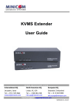
SMARTRACK 116 IP
SmartRack 116 IP - Quick Start Guide
QUICK START GUIDE
1. Introduction
3. Hardware kit contents
To take advantage of the full range of features, we recommend you read the
softcopy User Guide after performing the Quick Start procedure. It’s in PDF format
on the supplied CD or on our website www.minicom.com in the Support section.
Rail with front and rear bracket x 2,
for rack depth of 614 ~ 800 mm.
Right and left sides are different.
The SmartRack 116 IP extends your KVM (keyboard, video, and mouse) from any
computer or server over TCP/IP via LAN, WAN or Internet connection. Now you
can control, monitor and manage up to 16 remote servers from wherever you are,
inside or outside the organization. The SmartRack 116 IP is a cost-effective
hardware solution, for secure remote KVM access & control of 16
computers/servers from the BIOS level - independent of the OS. One local analog
or one remote digital IP user can access and control 16 multi-platform (PS/2, SUN,
USB) servers at a time.
Screws x4
Keys x 2.
4. Pre-installation guidelines
Long bracket x 2. (For increased rack
depth of 905 ~ 990mm)
Occupying just 1U of rack space, it’s the neat, space-saving way to control your
data rack. It comes with all the hardware you need to mount it, and is easy to
install.
To access servers, just slide out the drawer and flip up its top to display the large,
high resolution 17” TFT LCD display.
The display is (VGA/SVGA/XGA/SXGA compatible) with front-panel highquality controls and Touchpad for easy adjustment.
SMARTRACK 116 IP
•
Switch off all computers
•
Place cables away from fluorescent lights, air conditioners, and machines that
are likely to generate electrical noise
•
Ensure that the maximum distance between each computer and the SmartRack
116 IP does not exceed 30m/100ft
5. Connecting to a rack
Note! For increased rack depth of 800 ~ 990mm, first change the bracket to
the medium or long bracket, see section 5.1 on page 6.
Note! The illustrations below show the connections to one side of the SmartRack
116 IP. The connections are the same for the other side.
Medium bracket x 2. (For increased
rack depth of 800 ~ 905mm)
1. Move the rail until two screws appear, see Figure 1.
1.1 Compatibility
The SmartRack 116 IP is compatible with:
•
PS/2, SUN and USB computers/servers
•
Windows, Linux, UNIX and other major operating systems
Short bracket x 2
Figure 1 Exposing the 2 screws
2. System components
2. Loosen slightly the 7 screws as shown below.
The SmartRack 116 IP system consists of:
•
1 SmartRack 116 IP
•
1 RS232 Download cable (p/n 5CB40419)
•
ROCS - PS/2, USB. (Ordered separately). CAT5 cables (1.5m provided)
Bracket attachment x 2
Note! The short bracket and bracket attachment for a rack depth of 504~ 614 mm
and without a KVM switch connected to the drawer.
Flat screws x 6 (for rail mount to console body)
Screws x 6
Figure 2 Loosen 7 screws
3. Adjust the rear bracket to fit your cabinet, see below.
Technical support - [email protected]
© 2009 Copyright Minicom Advanced Systems. All rights reserved.
5UM21182 V1 12/09
QUICK START GUIDE
Bracket A with thumbscrew x 2
1
2
3
SMARTRACK 116 IP
QUICK START GUIDE
SMARTRACK 116 IP
Figure 12 Taking the rear bracket out
Figure 3 Adjusting the bracket
4. Install the front and rear bracket onto the cabinet, see figure below.
Figure 6 Sliding the SmartRack between the rails
8. Unlock and pull both left and right rail–lock switches together – see below –
and push the console all the way into the rack.
Figure 9 Console in the rack
5.1 Using the medium or longer bracket
For a rack depth of 800 ~ 905mm, use the medium bracket. For a rack depth of 905
~ 990mm, use the longer bracket.
3. Insert the medium/long bracket into the rail then adjust the bracket to fit your
cabinet.
4. Tighten at least 2~3 screws along the length you need. Note! For medium
bracket use the round screws
screws
, and for the long bracket use the flat
.See Figure 13.
To replace the bracket with the medium or longer bracket:
1. Loosen the 7 screws as shown below.
Figure 4 Installing front and rear bracket on cabinet
5. Tighten the 7 screws as shown below.
Figure 13 Inserting and tightening the long bracket
5. Repeat the above steps for the other side.
Figure 7 Rail–lock switch
9. Connect three flat screws to the rear of the console on both sides. See figure
below.
Figure 10 Loosening the 7 screws
Remove the six (different) screws as shown below.
6. Go to section 5 Connecting to a rack.
5.2 Connecting the KVM Switch 116 IP
1. Connect the bracket A to the sides of the Switch using the two 6mm screws
provided see figure below.
Figure 5 Tightening the 7 screws
6. Repeat the steps above to connect the other rail to the other side of the rack.
7. Slide the SmartRack console between the rails as shown below.
Figure 8 Connecting three flat screws to the rear of the console
The console now sits snugly in the rack, see Figure 9.
Figure 11 Removing the six screws
2. Take the rear bracket out, see below.
Figure 14 Connecting the bracket A to the sides of the Switch
4
5
6
7
QUICK START GUIDE
SMARTRACK 116 IP
2. Slide the Switch 116 IP into the rail and into the back of the SmartRack console
until you hear a click. See the figure below.
QUICK START GUIDE
6. The SmartRack Switch system configuration
You connect servers to the 116IP switch via ROCs. Figure 17 illustrate the basic
configuration of the 116IP system.
SMARTRACK 116 IP
7. Initial settings - Default IP address
6.2 Connecting ROCs to servers
Each computer/server is directly connected to the SmartRack switch via the
appropriate ROC using CAT5 cable in a star configuration. No external power is
needed at the remote ROCs. The ROCs draw their power from the computer’s
keyboard port (ROC PS/2) or from the USB port (ROC USB).
6.2.1 Connecting a ROC PS/2
You can connect the ROC PS/2 to a powered on computer, but it must be in the
following order:
MINICOM
SERIAL
SMARTRA CK 116IP SWI TCH
FLASH
LAN
9
10
11
12
13
14
15
16
1
2
3
4
5
6
7
8
1. Connect the Mouse connector to the computer’s Mouse port.
SMARTRACK 116IP SWITCH
Figure 15 Slide switch into back of SmartRack
3. Secure the Switch 116 IP to the rail by inserting the thumbscrews through the
bracket and into the rail and tightening them, see Figure 16.
2. Connect the Keyboard connector to the computer’s Keyboard port.
CAT5 cables
Up to 30M / 100ft
User over IP
Internet / VPN / LAN
3. Connect the Screen connector to the computer’s Video port.
Failure to connect in the above order while the server is running, may lead to the
mouse malfunctioning until the server is rebooted.
To servers
6.2.2 Connecting a ROC USB
ROCs
to servers
Figure 17 SmartRack 116IP Switch system configuration
6.1 The 116 switch
The ROC USB supports Windows 98 SE and later, MAC, SUN, SGI and all
modern Linux distributions.
To connect the ROC USB:
1. Connect the Screen connector to the computer’s Video port.
2. Connect the USB connector to the computer’s USB port.
Figure 16 Tightening the thumbscrews
MINICOM
SERIAL
9
10
11
12
13
14
15
16
LAN
1
2
3
4
5
6
7
8
FLASH
Flash
LAN (Ethernet)
(download)
connector connector
Server ports
Connect the network cable to the LAN port. This must be done before powering on
the SmartRack 116IP Switch.
Power
connector
Figure 18 116IP Switch ports
6.1.1 Connector table
Connector
Function
Serial
This port is for future Serial functionality
Flash
To update firmware of the analogue part of the 116 IP Switch
system - OSD, Switch, ROCs.
LAN
Connect to 10/100 Mbit Ethernet. Green LED illuminates when
unit is connected to a 100 Mbit/sec network. Yellow Led
illuminates when unit is connected to a 10 Mbit/sec network.
Server ports
Connect to servers via ROCs
8
QUICK START GUIDE
4. Press Enter. The Web interface opens at the Network Configuration page, see
Figure 19.
By default, SmartRack 116 IP boots with an automatically assigned IP address
from a DHCP (Dynamic Host Configuration Protocol) server on the network. The
DHCP server provides a valid IP address, gateway address and subnet mask.
To identify the IP address, the SmartRack 116 IP MAC address appears on the
underside of the SmartRack 116 IP box. The device number (D.N.) can also be
found there.
If no DHCP server is found on the network, SmartRack 116 IP boots with the static
IP address:192.168.0.155.
Note! If a DHCP server later becomes available, the unit picks up the IP settings
from DHCP server. To keep the static IP address, disable DHCP – explained in the
softcopy User Guide.
7.1 Static IP addresses for a number of units
Where you want to connect more than 1 SmartRack 116 IP to the same network
and there is no DHCP server, or you want to use static IP addresses, do the
following:
Connect the SmartRack 116 IP units one at a time and change the static IP address
of each unit before connecting the next unit.
8. Logging into the Web interface
6.3 Connecting to the network
SMARTRACK116IP SWITCH
The following sections provide instructions for setting the IP address for the
SmartRack 116 IP unit.
6.4 Connecting the CAT5 cables
Client computer operating system. - Windows 2000 or higher, with Firefox 3 or
Internet Explorer 7.0 or later version. Linux with Firefox 3.
Complete the initial setup via the Web configuration interface:
1. Connect one connector to the ROC’s RJ45 port.
2. Connect the other connector to one of the SmartRack Switch Server ports.
1. Open your Web browser and type the SmartRack 116 IP system IP address https://IP address/ - and press Enter. The login page appears.
3. Follow the above 2 steps for each computer.
2. In mode select Configuration mode..
6.5 Connecting the power supply
1. Connect the switch to the power supply using the Power cord provided. Only
use the Power cord supplied with the unit.
3. Type the default Administrator user name admin and password access (both
lower case).
2. Power on the switch.
9
10
11
SMARTRACK 116 IP
QUICK START GUIDE
SMARTRACK 116 IP
9.1.2 Selecting a computer
10. Starting a remote session
To select a computer:
1. Navigate to the desired computer line.
Or, type the port number of the desired computer.
2. Press Enter. The selected computer is accessed. A confirmation label appears
showing which computer is accessed.
Note! When the OSD is displayed you cannot select computers using the
keyboard hotkeys.
Figure 19 SmartRack 116 IP Web interface
At a Client computer open the web browser and type the SmartRack 116 IP’s IP
address. https://IP address. The Login page appears. Type your username and
password and press Enter. By default, the user name is: admin and the password is
access, (both lower case).
Note! There is a shortcut to the Configuration pages from the login page. In mode
you can toggle between the option to access a remote session or the configuration
pages.
To display the OSD:
1. Ensure there is no remote user connected. To disconnect the remote user press
the Local button on the SmartRack 116 IP.
2. Press Shift twice. The OSD Main window appears. See Figure 20. Lines with
yellow text show active computers. Lines with blue text show inactive
computers. The Type column indicates a computer “C” is connected to the port.
Session Profile
Video Settings
Keyboard
Settings
Power Control Settings
(Currently not operational)
10.1 Switching to a different server/device
To connect to a different server/device:
1. From the Toolbar, click
.
2. Click the desired server. The screen of the server appears.
. A list of connected servers/devices appears.
To complete the initial setup and log into the web interface please see the softcopy User
Guide on the supplied CD or on our website www.minicom.com in the Support section.
C=computer
Instruction
keys
Figure 20 OSD Main window
9.1.1 Navigating the OSD
To navigate up and down use the Up and Down arrow keys.
Figure 21 Remote console window
To exit the OSD or return to a previous window within the OSD press Esc.
12
13
14
Disconnect
Session
Target Switching Menu
Server name
To jump from one column to the next (when relevant) use the Tab key.
Full Screen
Mode
Figure 22 Toolbar icons
Toolbar
Port number
appears here
Mouse
Settings
When connecting you will download the Java client..
The screen of the currently selected Target Server with Minicom toolbar appears
see Figure 21.
9. The OSD
Locks Toolbar
15