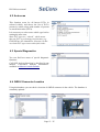
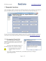
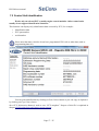
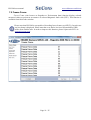
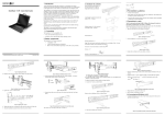
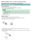
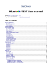
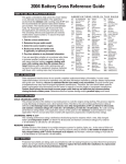
1
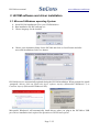
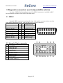
HiCOM
User manual
www.obdtester.com/hicom
Copyright © 2004 – 2014 SECONS s.r.o., http://www.secons.com/
All rights reserved.
HiCOM user manual
www.obdtester.com/hicom
SECONS Ltd. is not connected with Hyundai Motor Company in any way.
SECONS Ltd. is not liable for damages caused by using of software HiCOM.
Please read carefully this user manual before using the HiCOM application.
Before using the software please read license agreement.
Hyundai is registered trademark of Hyundai Motors or other owners.
Kia is registered trademark of Kia motors or other owners.
Dodge is registered trademark of Chrysler Group or other owners.
Inokom is registered trademark of Inokom company or other owners.
All trademarks used in this documentation or programs or any other material are used nominatively
for identification purposes only and may be property of their respective owners.
Page 2 / 25
Table of Contents
1 Introduction......................................................................................................................................4
1.1 Key features..............................................................................................................................4
1.2 Software updates.......................................................................................................................4
2 HiCOM software and driver installation..........................................................................................5
2.1 Microsoft Windows operating System......................................................................................5
2.2 Microsoft Windows 8 driver installation..................................................................................6
2.3 GNU/Linux System..................................................................................................................7
2.3.1 Requirements....................................................................................................................7
2.3.2 Setting up devices.............................................................................................................7
2.3.3 Installation.........................................................................................................................7
3 Diagnostic connectors used in Hyundai/Kia vehicles......................................................................8
3.1 OBD-II......................................................................................................................................8
3.2 Hyundai 12-pin connector........................................................................................................8
3.3 Kia 20-pin connector................................................................................................................9
4 Information about Hyundai/Kia control units ...............................................................................10
4.1 Hyundai ECU naming terminology........................................................................................10
4.2 Communication protocol........................................................................................................11
5 Preparation to diagnose...................................................................................................................11
6 HiCOM main menu........................................................................................................................12
6.1 Select Control Unit.................................................................................................................12
6.2 Auto-scan................................................................................................................................13
6.3 Special Diagnostics.................................................................................................................13
6.4 OBD-II Connector Location...................................................................................................13
6.5 Settings....................................................................................................................................14
6.6 About.......................................................................................................................................15
7 Diagnostic functions.......................................................................................................................16
7.1 Unrecognized Control Unit.....................................................................................................16
7.2 Control Unit Identification......................................................................................................17
7.3 Read fault code memory.........................................................................................................18
7.4 Clear Fault Codes....................................................................................................................18
7.5 Freeze Frame...........................................................................................................................19
7.6 Measured values.....................................................................................................................20
7.6.1 Graph display..................................................................................................................20
7.6.2 Display 3x3.....................................................................................................................20
7.6.3 Display list......................................................................................................................20
7.6.4 Save to log.......................................................................................................................20
7.7 Actuators activation................................................................................................................21
7.8 ECU Programming/Coding functions.....................................................................................22
8 Reporting bugs and improvement requests....................................................................................23
8.1 How to create Debug Log.......................................................................................................23
8.2 How to create ecu Snapshot....................................................................................................24
9 Known issues..................................................................................................................................25
10 Planned improvements.................................................................................................................25
HiCOM user manual
www.obdtester.com/hicom
1 Introduction
Thank you for purchasing the HiCOM diagnostic interface and software. HiCOM is
professional tool for diagnostics of Hyundai and Kia vehicles. Please read carefully this User
Manual before using the product.
We hope you'll find our products useful. In case you have any questions, problems or
feedback please contact as at [email protected]. We're here to help!
1.1 Key features
•
•
•
•
•
•
•
•
•
•
Fully multiplexed all-in-one smart USB2.0 interface
Automatic ECU recognition
Automatic vehicle scan
ECU Identification
Fault code (DTC) reading
Fault code clearing
Measured values / live data
Live data recording
Diagnostic protocol printing
Actuator tests
The HiCOM system works with Hyundai and Kia vehicles.
List of supported vehicles and control units including diagnosis capability can be found at
http://www.obdtester.com/hicom-eculist
1.2 Software updates
Updates of purchased software version are available for free download at
www.obdtester.com/downloads. User name = serial number of HiCOM diagnostic interface.
Password leave blank. The serial number can be found on a silver label of the interface or in
settings of HiCOM after performing “Test interface”. We recommend you to install updated version
at least once a month, because updates provide support for new ECUs and fix various issues.
We recommend you to update firmware in diagnostic interface by clicking on Settings → Upgrade
firmware every time you update the software.
Page 4 / 25
HiCOM user manual
www.obdtester.com/hicom
2 HiCOM software and driver installation
2.1 Microsoft Windows operating System
1. Insert HiCOM installation CD to your CD-ROM drive
2. Run installation file HiComSetup.exe
3. Choose language for the installer
4. Choose your destination folder for the HiCOM and click on Install button and after
successful installation click Close button.
HiCOM drivers are automatically updated during the HiCOM installation. When prompted to install
„unsigned“ drivers, click on Install this driver software anyway (Microsoft® Windows® 7) or
Continue Anyway (Microsoft® Windows® XP).
Microsoft® Windows® will automatically install drivers when you plug-in the HiCOM to USB
port. Driver installation isn't required for operation on GNU/Linux system.
Page 5 / 25
HiCOM user manual
www.obdtester.com/hicom
2.2 Microsoft Windows 8 driver installation
In case of problem with installing drivers on Windows 8, please follow these steps:
1. Press Windows Key + R
2. In the window that appears, type: “shutdown.exe /r /o /f /t 00”
3. Press "OK" button
4. The System will restart to a "Choose an option" screen
5. Select "Troubleshoot" from "Choose an option" screen
6. Select "Advanced options" from "Troubleshoot" screen
7. Select "Windows Startup Settings" from "Advanced options" screen
8. Click on "Restart" button
9. System will restart to "Advanced Boot Options" screen
10. Select "Disable Driver Signature Enforcement" (press number on keyboard for option shown on
screen)
11. Once the system starts, install the diagnostic interface drivers as you would on Windows 7
Windows Vista & 7 required signed all .sys files (we use usbser.sys shipped by Microsoft
with valid digital signature). Final version of Windows 8 requires also signed .inf file (which
is not in our case). The above procedure helps to override unsigned .inf file. Once driver is
installed, the program will work properly.
Page 6 / 25
HiCOM user manual
www.obdtester.com/hicom
2.3 GNU/Linux System
Our diagnostic application are tested to work under Linux. The applications can be run
under Linux, BSD or Apple OS/X on Intel x86 using Wine environment. The installer and
applications perform fully automated installation under these operating system.
2.3.1
Requirements
• Linux 2.6.x with USB support (or FreeBSD)
• USB CDC Driver
• Wine 1.0.1
Recent Debian Linux or Ubuntu meet the above requirements.
2.3.2
Setting up devices
Driver installation isn't required for operation on GNU/Linux system. Diagnostic
applications require access to /dev/ttyACMx devices from Wine environment. This can be set-up
very easily using these commands:
ln
ln
ln
ln
-s
-s
-s
-s
/dev/ttyACM0
/dev/ttyACM1
/dev/ttyACM2
/dev/ttyACM3
~/.wine/dosdevices/com5
~/.wine/dosdevices/com6
~/.wine/dosdevices/com7
~/.wine/dosdevices/com8
Diagnostic interface should be then visible from the HiCOM diagnostic application.
2.3.3
Installation
Programs can be installed by launching setup .exe file using wine, e.g. wine
HiComSetup.exe.
You can download the latest version of HiCOM from www.obdtester.com/downloads.
Page 7 / 25
HiCOM user manual
www.obdtester.com/hicom
3 Diagnostic connectors used in Hyundai/Kia vehicles
Location of OBD-II and manufacturer-specific (OBD-I) connectors is available in DLC
location database available from the HiCOM main menu.
3.1 OBD-II
Standard OBD2 connector is used usually since 1996 models to present (please note that
some models manufactured after 1996 still may use 12 or 20pin connector).
-
1
9
ISO9141 K Line
-
2
10
-
ISO9141 K Line
3
11
ISO9141 K Line
Ground (GND)
4
12
ISO9141 K Line
Signal ground (GND)
5
13
ISO9141 K Line
HS CAN High
6
14
HS CAN Low
ISO9141 K Line
7
15
ISO9141 L-Line
ISO9141 K Line
8
16
Battery voltage
3.2 Hyundai 12-pin connector
Pin
Description
1
Engine K-Line
2
Airbag K-Line
4
ABS K-Line
6
Gearbox K-Line
10
Engine L-Line
11
Speed signal
12
Ground (Battery-)
Page 8 / 25
HiCOM user manual
www.obdtester.com/hicom
3.3 Kia 20-pin connector
Pin
Description
1
Power after fuel pump
2
Cooling fan signal
3
Engine rotation speed / ignition signal
4
Ground
5
Battery positive voltage
6
7
Initial ignition management (coil 2)
8
ABS L-Line
9
Engine K-Line
10
Automatic transmission failure code
11
Blink code / Check Engine indicator
12
Ground
13
14
Airbag K-Line
15
ABS K-Line
16
Initial ignition management (coil 1)
17
Cruise-control K-Line
18
Automatic transmission L-Line
19
Engine L-Line
20
Engine monitor output
Page 9 / 25
HiCOM user manual
www.obdtester.com/hicom
4 Information about Hyundai/Kia control units
ECUs are usually identified and distinguished by:
– Territory (e.g. MEX=Mexico, India, Turkey, etc.)
– Selected features (e.g. ISG+, CPF-, etc.)
– Engine type (Leaded, Unleaded EOBD, Unleaded ALL, …)
– Installation date range (e.g. 2009/05/01-, …)
Feature list
Feature
Meaning
CPF
Diesel particulate filter
ISG
Idle Stop and Go
ESP
Electronic stabilization system
ETC
Engine type examples
Type example
Description
ENGINE Leaded
Leaded gasoline engine
ENGINE Unleaded OBD-II Unleaded gasoline engine, OBD2 compliant
ENGINE Unleaded EOBD Unleaded gasoline engine, European OBD2 compiant
ENGINE Unleaded MEX
Unleaded gasoline engine, Mexico market
ECUs do not have capability of self-identification and if multiple choices are possible, user
must select proper control unit.
4.1 Hyundai ECU naming terminology
PCM
Engine ECU control unit
IMMO
Immobilizer control unit
AT
Automatic Transaxle
SMARTRA
Smart Transponder Antenna
SMK
Smart key unit
IPM
Instrument Panel Module
BCM
Body Control Module
Page 10 / 25
HiCOM user manual
www.obdtester.com/hicom
4.2 Communication protocol
HiCOM supports these communication protocols:
Protocol
Diagnostic bus
Production
Usage
KW71 (Bosch)
ISO9141
1991 – 2001
Engine
ISO9141
ISO9141
1996 – present Engine, ABS, Airbag
KWP2000,
ISO9141
1996 – present All systems
ISO15765
CAN-BUS (ISO 11898) 2005 – present All systems
UDS (ISO 14229) CAN-BUS (ISO 11898) 2011 – present All systems
5 Preparation to diagnose
Before starting diagnosis, make sure that car ignition is turned ON. Connect your HiCOM
diagnostic interface to PC / laptop via USB. Interface test in settings of HiCOM must pass
successfully (more information in chapter Settings). Connect your HiCOM diagnostic interface to
OBD-II connector in the vehicle. You can find the OBD-II connector using HiCOM OBD-II
Connector Location image database.
Page 11 / 25
HiCOM user manual
www.obdtester.com/hicom
6 HiCOM main menu
HiCOM main menu is divided into two parts → Vehicle diagnostics and Miscellaneous functions.
Descriptions of single functions are given below.
6.1 Select Control Unit
Using this function you can connect to a specific control unit you wish to diagnose. You can choose
the control unit after exact selection of tested vehicle. Correct model year and model code selection
is essential for proper diagnostic functions.
We recommend to always try to identify vehicle based on VIN code.
All control units present in tested vehicle can be detected by Auto-scan function.
Incorrect model selection may result in wrong or incomplete live data, improper function of
actuator tests and coding functions, possibly resulting in damaged car components.
Page 12 / 25
HiCOM user manual
www.obdtester.com/hicom
6.2 Auto-scan
This function scans for all known ECUs in
selected vehicle, and shows the list of ECUs
present in vehicle along with number of present
or stored fault codes (DTCs).
It is necessary to select exact vehicle type before
starting the auto-scan.
Some ECU types are “shared”, which means
that one ECU is performing two functions (e.g.
ENGINE has also immobilizer function). In that
case both ECU types return same fault codes.
6.3 Special Diagnostics
You can find here menu of special diagnostic
functions.
CAN BUS Analysis functions is described in our
manual “CAN-BUS analysis information”
available at obdtester.com/downloads.
6.4 OBD-II Connector Location
Using this database you can check a location of OBD-II connector in the vehicle. The database is
constantly updated.
Page 13 / 25
HiCOM user manual
www.obdtester.com/hicom
6.5 Settings
All functions in settings are described below.
Language
Choose language of HiCOM user interface in the drop down menu.
Units type
You can choose metric or imperial unit system for measured values.
Interface port selection
Refresh - this button refreshes COM port selection drop down list. Correct COM port number
should be already chosen after connecting diagnostic interface via USB to PC and clicking on
Refresh button. If not, choose correct COM port number from the list. It is needed in order to
perform successful interface test.
Test interface – before each use of program, please test proper function of your connected
interface by clicking this button. After successful test, you can see a serial number of your interface
displayed below the COM port field, then firmware version and information about active licenses.
Activate license – this button is used for activating new license/s to use the program or special
functions. Internet connection is required. Standard license is already activated for all interfaces
before purchase.
Page 14 / 25
HiCOM user manual
www.obdtester.com/hicom
Upgrade firmware – use this button to upgrade firmware in your diagnostic interface every time
after installing the latest software version (available at www.obdtester.com/downloads). Do not
disconnect your interface during upgrading the firmware.
Device Manager – is used to finding out correct COM port number, or to reinstall drivers. Your
device appears as “ELM-USB Interface (COMx)” under “Ports (COM & LPT)”.
Bluetooth Manager – is a preparation to upcoming bluetooth feature. The button is currently
inactive.
Protocol settings
You can set various timings for each communication protocol. This is advanced feature used for
example when problems occur with connection to control unit caused by slower ECU response and
the like.
Restore Defaults – this button restores all modified timings of all protocols to default values.
Changing protocol settings is not required before normal use of the program. You will be
asked to make changes by our tech. support when solving your issue at [email protected]
if necessary.
Debug functions
By clicking on Save Debug button, you can capture the latest data from elapsed communication
between control unit and program into one file. Providing this file is required only by our technical
support. Based on these data, we are able to monitor the whole process of performed operation and
its correctness.
Use of debug function is important for successful resolution of any program failure or
verifying its causes. For more information on how to proceed, please read the following
chapter #8.Reporting bugs and improvement requests.
6.6 About
After clicking on “About” button, you can read a license agreement or check application version.
Page 15 / 25
HiCOM user manual
www.obdtester.com/hicom
7 Diagnostic functions
After connecting to chosen control unit, the following diagnostic menu is displayed. The diagnostic
menu is divided into three parts. Basic functions, Advance functions and Expert functions.
If control unit was identified uniquely, diagnostic menu will be available immediately, otherwise it
is necessary to select control unit variant as described in next chapter Unrecognized Control Unit
7.1 Unrecognized Control Unit
In a case of more ECU variants are
applicable for selected ECU type, the following
screen is displayed and user must select correct
ECU variant.
You can get more information about ECU
by clicking on Show ECU Identification button.
•
•
It is important choose correct ECU
for proper display of measured
values.
If you make a mistake in identification, you shouldn't perform any of coding or
programming functions.
Page 16 / 25
HiCOM user manual
www.obdtester.com/hicom
7.2 Control Unit Identification
Works only on selected ECUs, mainly engine control modules. Other control units
usually do not support identification functions.
This function can display only identification data accessed by ECU, for example:
•
Identification data
•
ECU part number
•
serial number
Please note that many vehicles do not have programmed VIN code or other data (such as
programming date/etc).
You can print identification by clicking on Print Values button or you can copy to clipboard
by clicking on Copy Values button.
Save ECU Information button is used to save “ECU snapshot”. Purpose of this file is explained in
chapter #8.Reporting bugs and improvement requests.
Page 17 / 25
HiCOM user manual
www.obdtester.com/hicom
7.3 Read fault code memory
This function allows to read and display diagnostic trouble codes saved in control unit
memory.
Note: Not all ECUs support fault code reading. In case Fault code memory reading is not
available, error message is displayed. Use live data or actuator tests to diagnose ECU problems in
such case.
7.4 Clear Fault Codes
This function clears fault codes stored in ECU memory.
Fault codes might appear again or under some conditions isn't possible to clear fault codes at
all. It is possible that in the presence of some faults control unit doesn't allow to clear fault codes or
fault is in no time written back to memory.
It is recommended to read memory by clicking on Re-read fault codes button again.
Page 18 / 25
HiCOM user manual
www.obdtester.com/hicom
7.5 Freeze Frame
Freeze Frame (also known as Snapshot or Environment data) function display selected
measured values as present at occurrence of selected diagnostic fault code (DTC). This function is
available from fault codes window.
Please note that HiCOM is not capable of decoding freeze frames on all ECUs. In such case
raw hex dump is displayed. Please note that even dealer-level tool (Hyundai/Kia GDS)
suffers from similar issue. In order to improve this function, please report such ECUs to
[email protected].
Page 19 / 25
HiCOM user manual
www.obdtester.com/hicom
7.6 Measured values
7.6.1
Graph display
This function displays two measured
values (also known as live data or sensor values)
simultaneously. Measured parameters can be
chosen from selectors at the top of the window.
Buttons + and – allow to accelerate or
decelerate speed of graph.
7.6.2
Display 3x3
For measuring 9 value simultaneously,
click on 3x3 View button.
7.6.3
Display list
To measure all available values
simultaneously, click on List view button.
Please note values means slower refresh rate.
7.6.4
Save to log
Measured values can be saved/logged to a file by clicking on Start logging button. The log
file is standard csv file and it is compatible with VagScope or can be imported to Microsoft Excel or
OpenOffice Calc.
Page 20 / 25
HiCOM user manual
www.obdtester.com/hicom
7.7 Actuators activation
This function can activate actuators and perform some actuators actions.
Make sure you understand consequences of activating ECU components. Also make sure
that activation conditions (engine idle, engine running, etc.) are met. Always consult all tests
with car repair handbook.
Page 21 / 25
HiCOM user manual
www.obdtester.com/hicom
7.8 ECU Programming/Coding functions
This feature allows to run coding functions. Note that some of the coding functions can not
be run when the engine is running and vice versa (some coding functions can not be run unless the
engine is running).
More
information
about
programming
functions
is
available
at
www.obdtester.com/downloads . Please note that this function is currently under development.
Page 22 / 25
HiCOM user manual
www.obdtester.com/hicom
8 Reporting bugs and improvement requests
Our customers can take advantage of our full technical support for free. In case you have any
difficulties with using HiCOM, do not hesitate to contact us directly at [email protected] or
through your distributor.
Please read carefully this chapter in order to provide us with all information so as we can resolve
your problem quickly.
Note:
Before sending support request for failing operation, please make sure you have met all conditions
required for the operation (e.g. you are entering correct data, correct engine temperature for DPF
regeneration, correct number of keys for engine start, etc).
In case of communication issues we recommend to check diagnostic plug connection and retry
procedure at least once, connection problems may result in erratic communication issues.
In case you encounter to failure of any program functions (e.g. fault codes reading/clearing,
coding functions, actuator tests, connecting to ECU …), or you're missing some function or
some function does not work sufficiently, please prepare the following data in your email
before sending your request to our technical support:
1. Detailed description of failure or your improvement request
2. Vehicle description - VIN code, model, manufacture year, engine type
3. Attach Debug Log (in case that required function doesn't work properly). This file captures
data from the latest communication between program and ECU, so we can detect failure
causes.
4. Attach Snapshot of tested ECU – this file contains important information about tested
control unit.
8.1 How to create Debug Log
It is necessary to perform operation that is not
working correctly first. Once failure occurs, go back
directly to settings in main menu (do not close the
program). Click on “Save Debug” button. Name and
save the file into well known directory in your
computer.
Enable “Debug mode” check box only at our special request.
This function is used to tell program enable special functions in diagnostics interface and to log
more data than required for normal operation.
Page 23 / 25
HiCOM user manual
www.obdtester.com/hicom
8.2 How to create ecu Snapshot
After connection to related control unit, click on
“Control Unit Identification”. In the following window
click on “Save ECU Information” button. Choose a
directory to save the file and confirm. Saving may take a
few minutes.
Please send all support requests along with required data attached to [email protected]. Your
case will be assigned with unique ticket number in order to communicate efficiently with you.
Also feel free to contact us with any suggestions for improvements in the software on the same email address. Your feedback is greatly appreciated.
Page 24 / 25
HiCOM user manual
www.obdtester.com/hicom
9 Known issues
– Freeze frame functionality is not guaranteed on all ECUs
– Communication with Hyundai Trajet 1999-2000 Gasoline 2.0 DOHC engine is not possible.
– Communication with Hyundai SantaFe 2001-2006 ABS 2WD control unit is not stable.
10 Planned improvements
The following improvements of user interface are planned for next release:
− Resizable windows
− Font size change option
− Screenshot to PDF or PNG
− Improved live data display
− Metric and imperial conversion
− Connection to online services
Page 25 / 25