1
SERVICE MANUAL
CODE: 00ZARCF2//A1E
DIGITAL COPIER/PRINTER/
MULTIFUNCTIONAL SYSTEM OPTION
INSERTER
MODEL
AR-CF2
CONTENTS
[1] PRODUCT OUTLINE . . . . . . . . . . . . . . . . . . . . . . . . . . . . . . . . . . . 1-1
[2] SPECIFICATIONS . . . . . . . . . . . . . . . . . . . . . . . . . . . . . . . . . . . . . 1-1
[3] EXTERNAL VIEWS AND INTERNAL STRUCTURES . . . . . . . . . . 3-1
[4] OPERATIONAL DESCRIPTION. . . . . . . . . . . . . . . . . . . . . . . . . . . 4-1
[5] DISASSEMBLY AND ASSEMBLY . . . . . . . . . . . . . . . . . . . . . . . . . 5-1
[6] MAINTENANCE . . . . . . . . . . . . . . . . . . . . . . . . . . . . . . . . . . . . . . . 6-1
[7] TROUBLESHOOTING . . . . . . . . . . . . . . . . . . . . . . . . . . . . . . . . . . 7-1
[8] ELECTRICAL SECTION. . . . . . . . . . . . . . . . . . . . . . . . . . . . . . . . . 8-1
Parts marked with “ ” are important for maintaining the safety of the set. Be sure to replace these parts with
specified ones for maintaining the safety and performance of the set.
SHARP CORPORATION
This document has been published to be used
for after sales service only.
The contents are subject to change without notice.
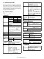
[1] PRODUCT OUTLINE
Paper sizes
This inserter is an optional unit for the AR-620 series of digital complex
machines. With the inserter installed, blank sheets or printed sheets
can be inserted as covers (made of cardboard) or tabbed sheets without being subject to the printing process (and without passing through
a fixing unit). When the inserter is combined with a finisher (optional)
and a punch unit (optional), printed sheets can proceed to the hole
punching or stapling process without being subject to the copying process (or without passing through the main unit).
Size detection
[2] SPECIFICATIONS
1. Basic specifications
A. Performance
Type of Installation
Delivery speed
Productivity
Transport
reference
Loading capacity
Offline function
Manual operation
section
Stapling
Saddle stitching
(With folding)
Punching
Paper jam
handling
Floorstanding
Through mode
(Horizontal
transportation):
Straight mode:
217mm min.
216mm max.
800mm/sec
1000mm/sec
217mm min. 800mm/sec
216mm max. 1000mm/sec
Saddle mode
217mm min. 800mm/sec
(Reverse):
216mm max. 1000mm/sec
50 cpm (when A4 or letter-sized insert sheets
are continuously transported/saddle mode not
applicable)
Center reference through (when horizontally
transported)
100 sheets max. (80 g/m2 or less)
Maximum loading height: 12 mm (80g/m2 or
greater)
Maximum loadable sheets: 30 (127g/m2 or
greater)
Factor 0.6 or less applied to above limitations
for special papers
Provided
Equipped with keys and LEDs
Possible
Possible
Possible
Paper feed/
Transport unit
Horizontal
transport unit
Types
Special papers
Compliant with the specifications both of the main
unit and the punch unit.
C. Mechanical specifications
External
dimensions
Product
dimensions
Packaged
dimensions
Footprint
Weight
Item enclosed
Product weight
Package weight
Inserter: 1
Paper feeding cover open/
close
Transportation guide open/
close
60 – 256gm2 (Normal paper, whose thickness
should be less than 256µm)
Normal paper, special paper (OHP films, colored
paper, punched paper, tabbed paper)
OHP films: Saddle mode (reverse) not applicable
Punched paper: 2, 3, or 4 holes
2 holes (φ6.5): Hole pitch: 80mm
2 holes (φ8):
Hole pitch: 70mm
3 holes (φ8):
Hole pitch: 108mm+108mm
4 holes (φ6.5): Hole pitch:
80mm+80mm+80mm
4 holes (φ6.5): Hole pitch:
21mm+70mm+21mm
(W) 320 x (D) 580 x (H) 1060 mm
∗ Latch unit and tray unit
excluded.
(W) 1295 x (D) 680 x (H) 516 mm
(W) 320 x (D) 580 mm
∗ Latch unit and tray unit
excluded.
Approx. 23kg
Approx. 32kg
2. Electrical specifications
Input voltage
Power consumption
B. Compatible paper types
Paper weight
Paper sizes that
can be stapled
Paper sizes that
can be saddle
stitched
Paper sizes that
can be punched
Ledger (LD), Legal (LG), Letter (LT), Letter R
(LTR), Foolscap, Executive R, Invoice R, 18K,
16K, 16K-R, Wide sheet
Width: 304.8mm max. (12 inches max.)
Length: 457.2mm max. (18 inches max.)
The 3 destinations below are user-definable
cm:
A3, B4, A4, A4R, B5, B5R, A5R
(Foolscap is manually specified on the
operation panel of main unit)
inch: LD, LG, LT, LTR, Executive R, Invoice R
China: 8K, 16K, 16K-R
∗ Mixed loading is not possible. When offline, stapling and punching are possible only for papers
that have the identical width (A3 and A4, B4 and
B5, LD and LT). Note that compatibility with the
finisher is not considered.
Compliant with the specifications both of the main
unit and the finisher.
Compliant with the specifications both of the main
unit and the saddle finisher.
Supplied from the main unit
DC+24V ± 10%
DC +5V ± 5%
DC+24V: 58.3W max.
DC +5V: 1.1W max.
3. Environmental conditions
Operating
conditions (normal
operation)
Transport/storage
environment
Temperature
Humidity
5 – 35°C
20 – 85%RH (No condensing)
Temperature
Humidity
–20 – 50°C
10 – 90%RH (No condensing)
4. Compliance
Safety standard
Electromagnetic
Compliance
AR-CF2 PRODUCT OUTLINE 1 - 1
UL: 60950 the 3rd edition
C-UL: CAN/CSA-C22. 2 No.60950 the 3rd edition
CE: EN60950 ITS (German GS mark)
VCCI: Class B
FCC: Class B
CE: EN50081-1 EN55024
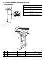
[3] EXTERNAL VIEWS AND INTERNAL STRUCTURES
1. External components
2
3
No.
1
4
1
Description
Paper feed tray
2
Paper guide
3
4
Top cover
Operator panel
5
Paper guiding
section
Front cover
Function
Place blank or printed sheets to be
inserted in this tray.
Adjust this guide according to the paper
size.
Open this cover to clear a paper jam.
Operate the staple and punch unit with this
panel (or with the operator panel of the
main unit).
Unlock the paper guiding section to clear a
paper jam.
Open this cover to remove jammed paper
from the finisher or saddle finisher.
5
6
6
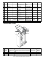
2. Sensors and switches
12
11
1
13
8
10
9
7
6
3
2
4
5
No.
Symbol
Description
Type
Function and operation
Output
1
JCK_S W
JAM cover open/
close switch
Microswitch
Detects that the JAM cover is
opened or closed.
When the JAM cover is opened,
TP37 turns HIGH.
2
H_SEN
Reverse sensor
Reflective sensor
Detects that a sheet to be
inserted is transported to the
reverse sensor.
When a sheet is detected, TP1
turns HIGH.
AR-CF2 EXTERNAL VIEWS AND INTERNAL STRUCTURES 3 - 1
Product name
(Model)
DE2L-FAAA
SENSOR
(SNS - SPI-337-01)
Manufacturer
HIROSE
CHERRY
PRECISION
SANYO
No.
Symbol
Description
Type
3
HI_SEN
Paper exit sensor
Photointerrupter
4
HYK_SEN
Photointerrupter
5
KC_SEN
6
S_SEN
Reverse unit open/
close sensor
Stand cover open/
close sensor
Set sensor
Photointerrupter
7
EMP_SEN
Empty sensor
Photointerrupter
8
REG_SEN
Registration sensor
Photointerrupter
9
TIM_SEN
Timing sensor
Photointerrupter
10
T_VR
Sheet width detection
potentiometer
Potentiometer
11
T_SEN
Tray sensor
Photointerrupter
12
TH_SEN
Photointerrupter
13
TS_SEN
Sub tray pullout
detection sensor
Sub tray retraction
detection sensor
Photointerrupter
Photointerrupter
Product name
(Model)
TLP1241 (C5)
TOSHIBA
TLP1241 (C5)
TOSHIBA
TLP1241 (C5)
TOSHIBA
TLP1241 (C5)
TOSHIBA
TLP1241 (C5)
TOSHIBA
When a sheet is detected, TP5
turns LOW.
TLP1241 (C5)
TOSHIBA
hen a sheet is detected, TP6
turns LOW.
TLP1241(C5)
TOSHIBA
The voltage of TP12 varies
between 0 V and 5 V depending
on the sheet width.
When a sheet is detected, TP13
turns LOW.
When the pullout status is
detected, TP14 turns LOW.
When the retracted status is
detected, TP15 turns LOW.
RDC505003A
ALPS
GP1A73A
SHARP
GP1A73A
SHARP
GP1A73A
SHARP
Function and operation
Output
Detects that a sheet to be
inserted is transported to the
paper exit sensor.
Detects that the reverse unit is
opened or closed.
Detects that the stand cover is
opened or closed.
Detects that the inserter is joined
to the main unit.
Detects presence/absence of a
sheet to be inserted in the paper
feed tray.
Detects that a sheet to be
inserted is transported to the
registration sensor.
Detects that a sheet to be
inserted is transported to the
timing sensor.
Detects the width of a sheet to
be inserted in the tray.
When a sheet is detected, TP7
turns LOW.
Detects the length of a sheet to
be inserted in the tray
Detects the pullout status of the
sub tray.
Detects the retracted status of
the sub tray.
When the reverse unit is
opened, TP9 turns LOW.
When the stand cover is
opened, TP10 turns LOW.
When the inserter is joined to
the main unit, TP16 turns HIGH.
When a sheet is detected, TP4
turns HIGH.
Manufacturer
3. Motors, solenoid, and clutch
3
5
1
6
2
7
4
No.
1
2
3
4
5
6
7
Symbol
K_MOT
H_MOT
Y_MOT
F_SOL
R_CL
PBA-PANEL
PBA-CONT
Description
Paper feed motor
Reverse motor
Horizontal transport
motor
Flapper solenoid
Registration clutch
Operation panel PWB
Main control PWB
Function
Feeds a sheet to be inserted from the tray.
Reverses and ejects a sheet to be inserted.
Transports a sheet to be inserted on the horizontal transport
path.
Switches over the flapper in the reversing operation.
Holds the registration rollers to maintain registration.
–
–
AR-CF2 EXTERNAL VIEWS AND INTERNAL STRUCTURES 3 - 2
Product name (Model)
23KM-K112-P5V
17PM-J507-P2VS
17PM-J507-P3VS
Manufacturer
MINEBEA
MINEBEA
MINEBEA
TDS-10SL-134
BJ-2.6-184
TDS
SHINKO
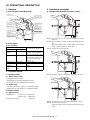
[4] OPERATIONAL DESCRIPTION
1. Structure
3. Operational description
A. Cross-sectional view (Main body)
A. Through-mode operation of inserter (Online)
Pickup roller
Paper feed roller
Separation roller
Empty sensor
Registration roller
Registration sensor
Timing sensor
Vertical
transport roller
Paper exit sensor
Horizontal
transport roller 1
Reverse roller
Horizontal
transport roller 2
Reverse sensor
Step 01: The inserter receives an operation command sent by the
main unit.
Step 02: The transport motor rotates at a speed specified by the main
unit.
B. Drive system
Horizontal transport rollers 1 (inlet rollers) and horizontal
transport rollers 2 (paper exit rollers) rotate.
[List of actuators]
Actuator
Description
Type
Paper feed
Pulse motor
motor
Transport motor
Pulse motor
Reverse motor
Reverse flapper
solenoid
Registration
clutch
Pulse motor
Solenoid
Electromagnetic
clutch
Components to be driven
Step 03: A sheet exits from the main unit.
Pickup roller, feed rollers,
separation rollers, registration
rollers, vertical transport rollers
Inlet rollers (horizontal
transport rollers 1), paper exit
rollers (horizontal transport
rollers 2)
Reverse rollers
Switch-over flapper in reverse
section
Registration roller lock clutch
2. Function outline
A. Operation mode
(1)
Step 04: The paper exit sensor detects the leading edge of the sheet.
Normal (online mode)
• Through (horizontal transport)
• Straight mode (normal paper feeding from inserter)
• Reverse mode (reverse paper feeding from inserter)
(2)
Offline mode
• Punching mode (inserter operation = normal paper feeding)
• Stapling mode (inserter operation = normal paper feeding)
B. Delivery speed
(1)
Delivery speed
• Straight mode:
217 mm or more;
216 mm or less;
• Saddle mode (reverse):
800 mm/sec
1000 mm/sec
420 mm/sec
Step 05: The paper exit sensor detects the trailing edge the sheet.
Step 06: The transport motor stops.
Horizontal transport rollers 1 and horizontal transport rollers
2 stop.
AR-CF2 OPERATIONAL DESCRIPTION 4 - 1
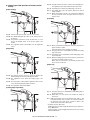
B. Normal paper feed operation of inserter (online/
offline)
Step 09: The paper feed motor starts to rotate in the forward direction.
The registration rollers and vertical transport rollers rotate.
Step 10: The timing sensor detects the leading edge of the sheet.
[Paper loading]
Step 11: The leading edge of the sheet passes between the vertical
transport rollers.
Step 12: When sheet transport needs to be suspended for adjusting
the space between sheets, the paper feed motor stops to
stop the sheet.
[Transport]
Step 01: A sheet is placed in the paper feed tray of the inserter.
Step 02: The START LED lights up in blue on the operator panel of
the inserter.
Step 03: An operation command is sent by the main unit, or a user
presses the START switch on the operator panel of the
inserter.
Step 04: The registration clutch is turned ON to lock the registration
rollers.
[Separation]
Step 13: When a predetermined waiting time period has passed, The
paper feed motor restarts.
(If the transport motor has stopped, it is started.)
Step 14: The paper exit sensor is turned ON, and detects the leading
edge of the sheet.
Step 15: The timing sensor is turned OFF, and the trailing edge of the
sheet is detected.
Step 16: When the trailing edge of the sheet leaves the vertical transport rollers, the paper feed motor stops.
(When there is a next sheet to be inserted, the paper feed
motor reverses to take it in.
[Paper exit]
Step 05: The paper feed motor reverses to lower the pickup roller,
thereby taking in the sheet from the paper feed tray.
Step 06: The registration sensor detects the leading edge of the
sheet.
Step 07: The sheet makes contact with the registration rollers to form
a loop, thereby stopping the paper feed motor.
Step 08: The registration clutch is turned OFF.
[Leading-edge registration]
Step 17: The paper exit sensor is turned OFF, and the trailing edge of
the sheet is detected.
Step 18: When there is no next sheet to be inserted, the transport
motor stops.
Note: While the transport motor (horizontal transport rollers 1 and
horizontal transport rollers 2) rotates at a speed specified by
the main unit in the online mode, it rotates at either of the
speeds shown below in the offline mode.
∗ Transport speed in offline mode
Small-sized sheet (of which length detected in the tray is 216 mm or
less): 1000 mm/sec
Large-sized sheet (of which length detected in the tray is more than
216 mm): 800 mm/sec
AR-CF2 OPERATIONAL DESCRIPTION 4 - 2
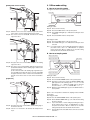
C. Reverse paper feeding operation of inserter
(online)
[Paper loading]
Step 09: The paper feed motor starts to rotate in the forward direction.
The registration rollers and vertical transport rollers rotate. If
the sheet is the first sheet, the flapper solenoid in the reverse
section is turned ON at this point of time.
Step 10: The timing sensor detects the leading edge of the sheet.
Step 11: The leading edge of the sheet passes between the vertical
transport rollers.
Step 12: When sheet transport needs to be suspended for adjusting
the space between sheets, the paper feed motor stops to
stop the sheet.
[Entering reverse section]
Step 01: A sheet is placed in the paper feed tray of the inserter.
Step 02: The START LED lights up in blue on the operator panel of
the inserter.
Step 03: The inserter reserves an operation command sent by the
main unit.
Step 04: The registration clutch is turned ON to lock the registration
rollers.
[Separation]
Step 13: When a predetermined waiting time period has passed, the
flapper solenoid is turned ON, the paper feed motor restarts,
and the reverse motor starts to rotate in the forward direction.
Step 14: The reverse sensor is turned ON, and detects the leading
edge of the sheet.
Step 15: When the trailing edge of the sheet leaves the timing sensor,
the paper feed motor starts to slow down to stop.
(After the paper feed motor has completely stopped, if there
is a next sheet to be inserted, the paper feed motor starts to
reverse to take it in.)
Step 05: The paper feed motor reverses to lower the pickup roller,
thereby taking in the sheet from the paper feed tray.
Step 06: The registration sensor detects the leading edge of the
sheet.
Step 07: The sheet makes contact with the registration rollers to form
a loop, thereby stopping the paper feed motor.
Step 08: The registration clutch is turned OFF.
[Leading-edge registration]
Step 16: The reverse sensor is turned OFF. The trailing edge of the
sheet is detected, and the flapper solenoid in the reverse
section is turned OFF. When the sheet travels a predetermined distance, the reverse motor stops.
AR-CF2 OPERATIONAL DESCRIPTION 4 - 3
4. Offline mode setting
[Exiting from reverse section]
A. How to set punching mode
The figure below shows the operator panel.
Start LED
Punch LED
Start switch
Punch switch
Setting procedure:
Step 01: Place a sheet in the tray.
Step 02: Press the PUNCH switch on the operator panel.
Step 17: When the reverse motor has completely stopped, the reverse
motor starts to reverse, and the transport motor starts.
Step 18: The reverse sensor is turned ON, and detects the leading
edge of the sheet.
Step 03: The PUNCH LED lights up to indicate that setting has been
completed.
Step 04: Press the START switch to start operation.
Canceling procedure:
Step 01: Press the PUNCH switch on the operator panel.
Step 02: The PUNCH LED goes out to indicate that setting has been
canceled.
Note: If you cannot make or cancel setting by following the respective
procedures above, refer to "5. LED indication on operation
panel" shown later. When no LEDs are lit, check the setting
made by the main unit and the inserter status.
B. How to set stapling mode
Staple mode LED 2
Staple mode LED 1
Start switch
Step 19: The paper exit sensor is turned ON, and detects the leading
edge of the sheet.
Step 20: The reverse sensor is turned OFF. When the sheet travels a
predetermined distance after its trailing edge is detected, the
reverse motor stops.
(If the next sheet waits at the leading-edge registration position, the flapper solenoid in the reverse section is turned ON,
the paper feed motor starts to rotate in the forward direction,
and the reverse motor starts to rotate in the forward direction.)
[Paper exit]
Staple mode LED 3
Start switch
Staple mode LED 4
Staple mode switch
Setting procedure:
Step 01: Place a sheet in the tray.
Step 02: Press the STAPLE MODE switch on the operator panel.
Step 03: Each time you press the switch, the STAPLE MODE LEDs
light up by turns in the following order: 1 → 2 → 3 → 4 → All
LEDs OFF → 1 → ... (When the saddle mode is cannot be
used, the order is: 1 → 2 → 3 → All LEDs OFF → 1 → ...)
Step 04: When the desired LED lights up, press the START switch to
start operation.
(Refer to the correspondence between the stapling modes and LEDs
shown later.)
Canceling procedure:
Step 01: Press the STAPLE MODE switch on the operator panel.
Step 02: All the STAPLE MODE LEDs go out to indicate that setting
has been canceled.
Note 1:
If you cannot make or cancel setting by following the respective procedures above, refer to "5. LED indication on operation panel" shown later. When no LEDs are lit, check the
setting made by the main unit and the inserter status.
Note 2:
The punching mode and saddle mode cannot be used at the
same time.
Step 21: The paper exit sensor is turned OFF, and the trailing edge of
the sheet is detected.
Step 22: If there is no next sheet to be inserted, the transport motor
stops.
AR-CF2 OPERATIONAL DESCRIPTION 4 - 4
The correspondence between the punching/stapling mode settings and LEDs is shown below.
Punch
LED
❍
❍
❍
❍
●
●
●
●
LED1
●
❍
❍
❍
❍
●
❍
❍
Staple mode LEDs
LED2 LED3 LED4
❍
❍
❍
●
❍
❍
❍
●
❍
❍
❍
●
❍
❍
❍
❍
❍
❍
●
❍
❍
❍
●
❍
Stapling mode
1-point stapling at back
2-point stapling
1-point stapling at front
Saddle stapling (saddle stitching)
Punching
Punching + 1-point stapling at back
Punching + 2-point stapling
Punching + 1-point stapling at front
∗ ●: means "Lit."
5. LED indication on operator panel
Status
Cause
Explanation
START LED
Red
Green
Empty tray
MODE LED
The selected MODE LED is lit.
Inserter problem
Finisher problem
Paper jam in inserter
Paper jam in finisher
Inserter alarm
Finisher alarm
Open inserter cover
Open finisher cover
Offline operation disabled
Inserter tray specified stapling
mode non-usable
Punching non-usable
Operation mode Stapling
disabled
Punching disabled
Full tray (considered as a kind of
finisher alarms)
Other
Paper-loaded tray
(Operable)
Paper-loaded
Inserter problem
tray(Non-operable) Finisher problem
Paper jam in inserter
Paper jam in finisher
Inserter alarm
Finisher alarm
Paper-loaded tray Open inserter cover
(Non-operable)
Open finisher cover
Incompatible paper size
The LED of the selected mode is lit.
The LED of the selected mode is lit.
The LED of the selected mode is lit.
The LED of the selected mode is lit.
The LED of the selected mode is lit.
The LED of the selected mode is lit.
The LED of the selected mode is lit.
The LED of the selected mode is
blinking.
The LED of the selected mode is lit.
Lit
Lit
Lit
Lit
Lit
Blinking
Blinking
The LED of the selected mode is lit.
The LED of the selected mode is lit.
The LED of the selected mode is lit.
The LED of the selected mode is lit.
The LED of the selected mode is lit.
The LED of the selected mode is lit.
The LED of the selected mode is lit.
The LED of the selected mode is lit.
A non-usable paper size "A4
lateral," etc. is added when the
saddle mode is selected: Extra size
Offline operation disabled
Inserter tray specified stapling
mode non-usable
Punching non-usable
Operation mode Stapling
disabled
Punching disabled
Full tray (considered as a kind of
finisher alarms)
Other
Waiting for start of
offline operation
In offline operation
Lit
Lit
The selected mode is nonusable.
The LED of the selected mode is
blinking.
The selected mode is disabled.
The LED of the selected mode is
blinking.
The tray corresponding to the
selected mode is full.
Main unit status "operation
disabled," finisher status "nonoperable," etc.
After a user presses the START
switch
The LED of the selected mode is lit.
Blinking
The LED of the selected mode is lit.
Blinking
The LED of the selected mode is lit.
Blinking The LED of the selected mode is lit.
Note: For LED status, each blank means "not lit."
AR-CF2 OPERATIONAL DESCRIPTION 4 - 5
6. Paper jam/error detection
A. List of Paper jams
Description
Not arrived at registration
sensor
Detection timing
At a time of separating a sheet
Not arrived at timing
sensor
At a time of leading-edge
registration
Not arrived at paper exit
sensor
At a time of paper exit in through
mode
At a time of paper exit in normal
paper feed mode
At a time of paper exit in reverse
paper feed mode
Not arrived at reverse
sensor
At a time of entering reverse
section
At a time of exiting from reverse
section
Stay at registration
sensor
Stay at timing sensor
Stay at paper exit sensor
Stay at reverse sensor
At a time of paper exit in normal
paper feed mode
At a time of entering reverse
section in reverse paper feed mode
At a time of paper exit in normal
paper feed mode
At a time of entering reverse
section in reverse paper feed mode
At a time of paper exit in through
mode
At a time of paper exit in normal
paper feed mode
At a time of paper exit in reverse
paper feed mode
At a time of entering reverse
section
At a time of exiting from reverse
section
Explanation
A paper jam is detected if the registration sensor is not turned ON, which means
absence of a sheet, even when the paper feed motor has been driven for a fixed
distance after the pickup roller starts to lower.
A paper jam is detected if the timing sensor is not turned ON, which means
absence of a sheet, even when the registration rollers (paper feed motor) have
been driven for a fixed distance after they are started.
A paper jam is detected if the paper exit sensor is not turned ON by the leading
edge of a sheet, which means absence of a sheet, even when the transport motor
has been driven for a fixed distance after the main unit sends a paper exit
command.
A paper jam is detected if the paper exit sensor is not turned ON, which means
absence of a sheet, even when the leading edge of a sheet has traveled a fixed
distance after it reaches the paper exit rollers (horizontal transport rollers 2).
A paper jam is detected if the paper exit sensor is not turned ON, which means
absence of a sheet, even when a sheet has been transported a fixed distance by
the transport motor after the reverse sensor is turned ON, which means presence
of a sheet.
A paper jam is detected if the reverse sensor is not turned ON, which means
absence of a sheet, even when the reverse motor has been driven for a fixed
distance after leading-edge registration.
A paper jam is detected if the reverse sensor is turned ON, which means absence
of a sheet, even when the reverse motor has been driven for a fixed distance
while a sheet is exiting from the reverse section.
A paper jam is detected if the registration sensor is not turned OFF, which means
presence of a sheet, even when the paper feed motor has been driven for a
predetermined amount after a sheet reaches the starting position of leading-edge
registration.
A paper jam is detected if the timing sensor is not turned OFF, which means
presence of a sheet, even when the paper feed motor has been driven for a fixed
distance after the registration sensor is turned OFF, which means absence of a
sheet.
A paper jam is detected if the paper exit sensor is not turned OFF, which means
presence of a sheet, even when the transport motor has been driven for a
predetermined amount after the paper exit sensor is turned ON, which means
presence of a sheet.
A paper jam is detected if the paper exit sensor is not turned OFF, which means
presence of a sheet, even when the transport motor has been driven for a fixed
distance after the trailing edge of a sheet reaches the paper exit rollers (horizontal
transport rollers 2).
A paper jam is detected if the reverse sensor is not turned OFF, which means
presence of a sheet, even when the reverse motor has been driven for a fixed
distance after the timing sensor is turned OFF, which means absence of a sheet.
A paper jam is detected if the reverse sensor is not turned OFF, which means
presence of a sheet, even when the reverse motor has been driven for a
predetermined amount after the reverse sensor is turned ON, which means
presence of a sheet.
B. Error detection
(2)
(1)
Explanation:
EEPROM errors
Reverse sensor adjustment error
1) When the DA output exceeds the upper limit
Explanation:
1) Timeout error
The EEPROM is being programmed even after a predetermined
time period (150 msec) has passed.
2) Writing error
The written data does not match the read data even when writing
and reading are retried.
3) Reading error
Even when the DA output is increased, the AD input value does
not fall within the appropriated range.
2) When the DA output is less than the lower limit
Even when the DA output is decreased, the AD input value does
not fall within the appropriated range.
C. Alarm detection
Explanation:
Checking pieces of data read from three sources results in mismatch even when checking is retried.
An alarm is issued because the size of a sheet in the tray cannot be
correctly detected when both the sub tray pullout detection sensor and
the sub tray retraction detection sensor are turned OFF.
Indication:
Shown by a LED on the operator panel of the inserter or of the main
unit as an inserter alarm.
AR-CF2 OPERATIONAL DESCRIPTION 4 - 6
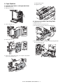
[5] DISASSEMBLY AND ASSEMBLY
B. Torque Limiter & Separation Roller
1) Open the top cover.
1. Paper Feed Separation Unit
2) Remove the maintenance cover.
A. Pickup Roller & Paper Feed Roller
1) Open the top cover
3) Turn the separation roller unit to remove.
2) Remove the maintenance cover.
4) Remove the torque limiter and the separation roller.
A: Torque limiter
3) Turning the paper feed unit, remove the paper feed roller guide.
B: Separation roller
A
B
4) Remove the pickup roller and paper feed roller.
A: Pickup roller
B: Paper feed roller
A
B
AR-CF2 DISASSEMBLY AND ASSEMBLY 5 - 1
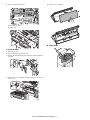
2. Paper Feed Unit
A: Horizontal pass roller 1
A. Horizontal Pass Roller 1 and Registration Roller
B: Registration roller
1) Open the top cover.
2) Open the mount cover.
B
A
B. Horizontal Pass Roller 2 and Timing Roller
1) Open the top cover.
2) Remove the front cover and rear cover.
3) Remove the front cover.
3) Disconnect the connector to remove the operating unit.
4) Remove the rear cover.
4) Disconnect the connector, tray support and tray spring guide spindle to remove the tray unit.
5) Remove the opening and closing cover supports and plastic Erings to remove the top cover.
AR-CF2 DISASSEMBLY AND ASSEMBLY 5 - 2
5) Remove the finisher latch cover.
5) Remove the cover bracket.
A: Horizontal pass roller 2
B: Timing roller
B
A
D. Paper Guide
C. Reverse Roller
1) Open the top cover.
2) Remove the front cover and rear cover.
3) Remove the finisher fixing bolt to remove the finisher positioning
stay unit.
4) Remove the reverse supports and plastic E-rings to remove the
reverse unit.
AR-CF2 DISASSEMBLY AND ASSEMBLY 5 - 3
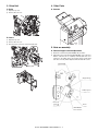
3. Drive Unit
4. Other Parts
A. Belts
A. Sensors
1) Open the top cover.
2) Remove the rear cover.
B. Gears
1) Open the top cover.
2) Remove the rear cover.
3) Disconnect the connector to remove the drive unit.
5. Note on assembly
A. Reverse flapper solenoid adjustment
1) Rotate the solenoid lever (LVR-FM-SOL) fully clockwise.
2) Adjust the position of the bracket (BKT-FM-SOL) of the solenoid so
that the solenoid's arm is completely retracted (that there is no
clearance in the rubber spacer, the stopper E-ring, and the main
unit of the solenoid). When adjusted, fix the bracket with screws.
LVR-FM-SOL
Stopper E-ring
Rubber spacer
Solenoid
main unit
Screw
BKT-FM-SOL
AR-CF2 DISASSEMBLY AND ASSEMBLY 5 - 4
[6] MAINTENANCE
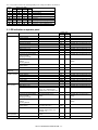
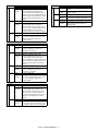
1. Maintenance list
✕ Check ❍ Cleaning ▲ Replace ∆ Adjust
(Clean, replace, and adjust, if necessary.)
Unit name
Paper separate
section
Transport
section
Drive section
Others
✩ Lubricate
AR-M550U/M550N
(PM: 250K)
AR-M620U/M620N
(PM: 300K)
No.
Part name
1 Pickup roller / Paper feed rollers
2 Torque limiter
3 Transport rollers
4 Transport paper guides
5 Gears and their related parts
6 Belts
7 Sensors
❏ Move position
When
calling
✕
✕
✕
❍
✕
✕
250K 500K 750K 1000K 1250K 1500K 1750K 2000K
Remarks
300K 600K 900K 1200K 1500K 1800K 2100K 2400K
❍
✕
❍
❍
✩
✕
✕
❍
✕
❍
❍
✩
✕
✕
❍
✕
❍
❍
✩
✕
✕
❍
✕
❍
❍
✩
✕
✕
❍
✕
❍
❍
✩
✕
✕
❍
✕
❍
❍
✩
✕
✕
❍
✕
❍
❍
✩
✕
✕
❍
✕
❍
❍
✩
✕
✕
(Note)
(Note)
(Specified positions)
(Note) Reference for replacement: Replace referring to the counter
value at the paper entry of the inserter.
Paper feed roller and its related parts: 150K or one year
Torque limiter: 400K
2
7
6
5
1
6
7
7
4
3
3
4
7
7
AR-CF2 MAINTENANCE 6 - 1
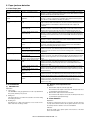
[7] TROUBLESHOOTING
Problem
Case1
Case2
Case3
Case4
Problem
Case1
The inserter does not perform at all when the main
switch of the main unit is turned ON.
Cause
Loose contact with the main unit
Check and Check that each connector is firmly
remedy
connected.
Cause
Loose contact of the connector terminal of
the wire (interface harness) connecting
with the main unit
Check and Check continuity in between the
remedy
connector terminals. Replace the
connection wire if no continuity is
measured
Cause
JAM cover open/close switch fault
Check and Check continuity between the switch
remedy
contacts., Replace the contacts if no
continuity is measured.
Cause
Controller PCB fault
Check and Check that 24 V DC and 5 V DC are
remedy
supplied from the main unit after the
above cases 1 to 3 are confirmed. If 24 V
and 5 V are not present at CN1-2 pin and
IC5-32 pin on the PCB, replace the
controller PCB.
Case2
Case3
Case4
Case5
Problem
Case1
Case2
Case3
Problem
Case1
Case2
Case3
The paper feed motor does not operate.
The reverse motor does not operate.
The horizontal transport motor does not operate.
Cause
Loose contact of the motor connector
terminal
Check and Check continuity of the connector
remedy
contacts.(CN1 to 3)
Cause
Disconnection of the motor coil
Check and Check continuity between the connector
remedy
terminals. Replace the connection wire if
no continuity is measured.
Cause
Controller PCB fault
Check and If the motor does not operate in the motor
remedy
single operation mode, replace the
controller PCB.
The paper is delivered without being reversed in
the reverse paper feed mode.
Cause
Connector terminal fault of the reverse
solenoid
Check and Check continuity of the connector
remedy
contact.(CN4)
Cause
Disconnection of the solenoid coil
Check and Inspect the coil for continuity. Replace the
remedy
coil if no continuity is measured.
Cause
Controller PCB fault
Check and If the solenoid does not perform in the
remedy
solenoid single operation mode, replace
the controller PCB.
Case6
Case7
Problem
Case1
Case2
Paper jam is displayed on the system display.
Cause
Paper jam
Check and Visual observation. Take out paper jams.
remedy
Cause
Reverse sensor fault
Check and Measure a voltage of TP2 on the
remedy
controller PCB and check that 3 to 3.6 V
is observed when no paper is stacked,
and that 1.5 V or less is observed when
paper is stacked. Replace the sensor if
the measured voltage exceeds these
ranges.
Cause
Paper exit sensor fault
Check and Measure a voltage of TP7 on the
remedy
controller PCB and check that 5 V is
observed when no paper is stacked, and
that 1 V or less is observed when paper is
stacked. Replace the sensor if the
measured voltage exceeds these ranges.
Cause
Empty sensor fault
Check and Measure a voltage of TP4 on the
remedy
controller PCB and check that 1 V or less
is observed when no paper is stacked,
and that 5 V is observed when paper is
stacked. Replace the sensor if the
measured voltage exceeds these ranges.
Cause
Registration sensor fault
Check and Measure a voltage of TP5 on the
remedy
controller PCB and check that 5 V is
observed when no paper is stacked, and
that 1 V or less is observed when paper is
stacked. Replace the sensor if the
measured voltage exceeds these ranges.
Cause
Timing sensor fault
Check and Measure a voltage of TP6 on the
remedy
controller PCB and check that a 5 V is
observed when no paper is stacked, and
that 1 V or less is observed when paper is
stacked. Replace the sensor if the
measured voltage exceeds these ranges.
Cause
Controller PCB fault
Check and If the problem is not solved with the
remedy
sensors whose level changes when each
is turned ON/OFF, replace the controller
PCB.
The machine does not detect the paper.
Cause
Tray sensor fault
Check and Measure a voltage of TP13 on the
remedy
controller PCB and check thatV is
observed when no paper is stacked, and
that 1 V or less is observed when paper is
stacked. Replace the sensor if the
measured voltage exceeds these ranges.
Cause
Controller PCB fault
Check and If the problem is not solved with a change
remedy
in the sensor level after the above case 1
is confirmed, replace the controller PCB.
AR-CF2 TROUBLESHOOTING 7 - 1
Problem
Case1
Case2
Case3
Problem
Case1
Case2
Case3
Case4
Problem
Case1
Case2
Tray alarm is displayed on the system display.
Cause
Sub-tray pulling detection sensor fault
Check and Measure a voltage on TP14 on the
remedy
controller PCB and check that 5 V is
observed when the sub-tray is in place,
and that 1 V or less is observed when the
sub-tray is pulled out. Replace the sensor
if the measured voltage exceeds these
ranges.
Cause
Sub-tray pulling detection sensor fault
Check and Measure a voltage of TP15 on the
remedy
controller PCB and check that 5 V is
observed when the tray is in place, and
that 1 V or less is observed when the tray
is pulled. Replace the sensor if the
measured voltage exceeds these ranges.
Cause
Controller PCB fault
Check and If the problem is not solved by a change in
remedy
the sensor level after the above cases 1
and 2 are confirmed, replace the
controller PCB.
Problem
Case1
Case2
Case3
The registration clutch does not perform.
Cause
Loose contact of the clutch connector
terminal
Check and Check continuity of the connector
remedy
contacts. (CN4)
Cause
Disconnection of the clutch coils
Check and Inspect the coils for continuity. Replace
remedy
the coils if no continuity is measured.
Cause
Controller PCB fault
Check and If the clutch does not perform in the clutch
remedy
single operation mode, replace the
controller PCB.
Cover open is displayed on the system display.
Cause
JAM cover open/close switch fault
Check and Check continuity between the switch
remedy
contacts., Replace the switch if no
conduction is measured.
Cause
Reverse unit open/close sensor fault
Check and Measure a voltage of TP9 on the
remedy
controller PCB and check that 1 V or less
is observed when the reverse unit is
open, and that 5 V is observed when the
reverse unit is closed. Replace the sensor
if the measured voltage exceeds these
ranges.
Cause
Rack cover open/close sensor fault
Check and Check continuity between the switch
remedy
contacts. Replace the sensor if no
conduction is measured.
Cause
Controller PCB fault
Check and If the problem is not solved by a change
remedy
in the sensor level after the above cases
1 to 3 are confirmed, replace the
controller PCB.
Inserter unset is displayed on the system display.
Cause
Set sensor fault
Check and Measure a voltage of TP16 on the
remedy
controller PCB and check that 5 V is
observed when the inserter is set, and
that 1 V or less is observed when the
inserter is not set. Replace the sensor if
the measured voltage exceeds these
ranges.
Cause
Controller PCB fault
Check and If the problem is not solved by a change
remedy
in the sensor level after the above case 1
is confirmed, replace the controller PCB.
AR-CF2 TROUBLESHOOTING 7 - 2
[8] ELECTRICAL SECTION
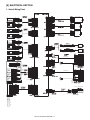
1. Actual Wiring Chart
Paper Feed Motor
Housing
Contact
Reverse Sensor
Reverse Motor
Housing
Contact
Paper Exit Sensor
Horizontal
Transport Motor
Reverse Unit Open/Closed
Sensor
Housing
Contact
Chassis Cover Open/Closed
Sensor
Set Sensor
Flapper Solenoid
Empty Sensor
Registration Clutch
Registration Sensor
Housing
Contact
Main Unit I/F
Timing Sensor
Tray
Tray Volume
Housing
Contact
Housing
Contact
Contact
Housing
Contact
Housing
Contact
Tray Sensor
Finisher I/F
Housing
Contact
Tray Drawn
Sensor
Housing
Contact
Housing
Tray Folded
Sensor
Contact
Housing
Housing
Contact
Contact
Contact
JAM Cover Open/Closed SW
Housing
Contact
Operation Panel
BE:
BN:
BK:
RD:
YW:
WE:
OE:
GY:
SB:
PK:
VT:
Blue
Brown
Black
Red
Yellow
White
Orange
Gray
Sky-blue
Pink
Violet
AR-CF2 ELECTRICAL SECTION 8 - 1
Sleeve
FASTON Terminal
2. Circuit Description
A. Outline
This circuit controls paper feed, transport, reverse, and delivery.
This circuit consists of the following divisions: managing signals from
the sensors, the switches, and the main unit; driving the motors, the
solenoid, and the clutch; the CPU and associated circuits.
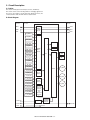
B. Block Diagram
Main Unit
Inserter
Finisher
RXD0
RXD1
COMMUNICATION
CIRCUIT
SGND
SGN
TXD0
TXD1
H_SEN
HI_SEN
HYK_SEN
ROM
KC_SEN
S_SEN
EMP_SEN
REG_SEN
EEP ROM
SENSORS
INPUT
CIRCUIT
F_SOL
CPU
TIM_SEN
R_CL
T_VR
T_SEN
TH_SEN
TS_SEN
DRIVER
P_ST_SW
P_MO_SW
SW
INPUT
CIRCUIT
P_PN_SW
P_PN_LED
P_MO_LED1
H_MOT
LED
DRIVE
CIRCUIT
Y_MOT
P_MO_LED2
P_MO_LED3
P_MO_LED4
P_ST_LED1
P_ST_LED2
DC+24V
JAM COVER
OPEN/CLOSED
DETECTION
CIRCUIT
(24V
CONDUCTIVE
DETECTION)
JCK_SW
INRUSH
CURRENT
LIMITING
CIRCUIT
DC+24V
DC+5V
K_MOT
DC+24V
DC+5V
AR-CF2 ELECTRICAL SECTION 8 - 2
C. Circuit Detail
(1) Communication Circuit
<1> TxD signal
<2> RxD signal
Main Unit
Main Unit
Finisher
Finisher
This circuit communicates with the main unit and the finisher.
TxD0 and TxD1 are data signals transmitted from the main unit and the finisher to the inserter. RxD0 and RxD1 are data signals transmitted from the
inserter to the main unit and the finisher. Logical 1 is represented by +5V, and logical 0 is represented by 0V.
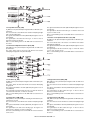
(2) Sensor Input Circuits
<1> Reverse Sensor (H_SEN)
Reverse Sensor
H_SEN uses the reflective sensor integrated with an LED and a phototransistor.
The signal input to the CPU follows the logic: "H" when a sheet is
detected, "L" when not detected.
The sensor detects a sheet between the sensor and the opposite
reflector interrupting the light path.
The analog signal is transmitted to CPU (IC-Pin105) through no comparator.
The CPU (IC6-Pin94, 95, 96) output is transmitted to the sensor to light
the LED through the D/A converter (IC13), the operational amplifier
(IC15.2), and the transistor (Q1). Meanwhile the signal is transmitted to
the CPU (IC6-Pin30) through the noise filters (R4, C2) and the comparator (IC1.1).
R1 and R10 divide the +5V voltage which is applied to the comparator
as the reference voltage.
R13 is used to make the reference voltage have hysteresis.
AR-CF2 ELECTRICAL SECTION 8 - 3
Paper Exit Sensor
Reverse Unit Open/Closed Sensor
Chassis Cover Open/Closed Sensor
<2> Paper Exit Sensor (HI_SEN)
HI_SEN uses the photointerrupter integrated with an LED and a phototransistor.
The sensor detects a sheet with the lever actuator interrupting the light
path of the photointerrupter.
The signal is transmitted to the CPU (IC6-Pin106) through the noise filters (R25,C9).
The signal input to the CPU follow the logic: "L" when a sheet is
detected, "H" when not detected.
R39 is a current limiting resistor for the LED. R34 is a load resistor for
the sensor.
<3> Reverse Unit Open/Closed Sensor (HYK_SEN)
HYK_SEN uses the photointerrupter integrated with an LED and a
phototransistor.
The sensor detects state of the reverse unit with the lever actuator
interrupting the light path of the photointerrupter.
The signal is transmitted to the CPU (IC6-Pin108) through the noise filters (R21,C7).
The signal input to the CPU follows the logic: "L" when the reverse unit
is open, "H" when closed.
R37 is a current limiting resistor for the LED. R32 is a load resistor for
the sensor.
<4> Chassis Cover Open/Closed Sensor (KC_SEN)
KC_SEN uses the photointerrupter integrated with an LED and a phototransistor.
The sensor detects state of the chassis cover with the lever actuator
interrupting the light path.
The signal is transmitted to the CPU (IC6-Pin109) through the noise filters (R29,C11).
The signal input to the CPU follows the logic: "L" when the chassis
cover is open, "H" when closed.
R41 is a current limiting resistor for the LED. R36 is a load resistor for
the sensor.
Set Sensor
Empty Sensor
Registration Sensor
Timing Sensor
<5> Set Sensor (S_SEN)
<7> Registration Sensor (REG_SEN)
S_SEN uses the photointerrupter integrated with an LED and a phototransistor.
The sensor detects the main unit with the lever actuator interrupting
the light path.
The signal is transmitted to the CPU (IC6-Pin2) through the noise filters (R56,C16).
The signal input to the CPU follows the logic: "H" when the inserter is
connected to the main unit, "L" when not connected.
R59 is a current limiting resistor for the LED. R58 is a load resistor for
the sensor.
REG_SEN uses the photointerrupter integrated with an LED and a
phototransistor.
The sensor detects a sheet with the lever actuator interrupting the light
path.
The signal is transmitted to the CPU (IC6-Pin32) through the noise filters (R14,C5).
The signal input to the CPU follows the logic: "L" when a sheet is
detected, "H" when not detected.
R17 is a current limiting resistor for the LED. R16 is a load resistor for
the sensor.
<6> Empty Sensor (EMP_SEN)
<8> Timing Sensor (TIM_SEN)
EMP_SEN uses the photointerrupter including the LED and the phototransistor in one unit.
The sensor detects a sheet with the lever actuator interrupting the light
path.
The signal is transmitted to the CPU (IC6-Pin31) through the noise filters (R7,C4).
The signal input to the CPU is the following logic: the signal is "H"
when a sheet is detected, "L" when not detected.
R12 is the current limiting resistor for the LED. R11 is the load resistor
for the sensor.
TIM_SEN uses the photointerrupter integrated with an LED and a phototransistor.
The sensor detects a sheet with the lever actuator interrupting the light
path.
The signal is transmitted to the CPU (IC6-Pin33) through the noise filters (R19,C6).
The signal input to the CPU follows the logic: "L" when a sheet is
detected, "H" when not detected.
R18 is a current limiting resistor for the LED. R31 is a load resistor for
the sensor.
AR-CF2 ELECTRICAL SECTION 8 - 4
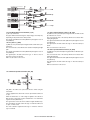
Paper Width Detection Potentiometer
Tray Sensor
Sub Tray Drawn Detection Sensor
Sub Tray Folded Detection Sensor
<9> Paper Width Detection Potentiometer (T_VR)
<11> Sub Tray Drawn Detection Sensor (TH_SEN)
T_VR is a potentiometer.
TH_SEN uses the photointerrupter integrated with an LED and the
phototransistor in one unit.
The paper width is detected using the output voltage, which may vary
depending on the potentiometer's knob position.
The signal is transmitted to the CPU (IC6-Pin112) through the noise filters (R48,C12).
The sensor detects state of the sub tray with the lever actuator interrupting the light path.
<10> Tray Sensor (T_SEN)
The signal is transmitted to the CPU (IC6-Pin127) through the noise filters (R44,C14).
T_SEN uses the photointerrupter integrated with an LED and a phototransistor.
The signal input to the CPU follows the logic: "L" when the sub tray is
drawn.
The sensor detects a sheet with the lever actuator interrupting the light
path.
R51 is a load resistor for the sensor.
The signal is transmitted to the CPU (IC6-Pin126) through the noise filters (R46,C15).
TS_SEN uses the photointerrupter integrated with an LED and a phototransistor.
The signal input to the CPU follows the logic: "L" when a sheet is
detected, "H" when not detected.
The sensor detects state of the sub tray with the lever actuator interrupting the light path.
R52 is a load resistor for the sensor.
The signal is transmitted to the CPU (IC6-Pin128) through the noise filters (R42,C13).
<12> Sub Tray Folded Detection Sensor (TS_SEN)
The signal input to the CPU follows the logic: "L" when the sub tray is
folded.
R50 is a load resistor for the sensor.
<13> JAM Cover Open/Closed Switch (JCK_SW)
JCK_SW is the JAM cover open/closed detection switch using the
microswitch.
+24V is supplied to the switch. The contacts open when the JAM cover
is open.
When the switch turns on, +24V voltage is applied to the cathode of
ZD2, the base current flows to Q12, and Q12 turns on to transmit the
signal to the CPU (IC6-Pin111).
The signal is also used as the +24V conduction signal simultaneously.
The signal input to the CPU follows the logic: "H" when the JAM cover
is open, "L" when closed.
The +24V conduction signal follows the logic: "L" when the +24V voltage is conducted.
AR-CF2 ELECTRICAL SECTION 8 - 5
(3) Motor Drive Circuits
<1> Paper Feed Motor Drive Circuit (K_MOT)
Paper Feed MOT
Not Mounted
This circuit rotates/stops K_MOT and controls its rotational direction
and the motor current. The circuit consists of the CPU (IC6), the D/A
converter (IC13), the constant-current chopper driver IC (IC9), and
other elements.
The analog signal from the D/A converter (IC13-Pin11) is divided into
the constant voltage by R53 and R54. The divided voltage is applied to
IC9-Pin9,11 to set the motor current.
The signals of the stepping-motor drive excitation pattern from the
CPU (IC6-Pin37,38,70,71) control the motor rotation speed and rotational direction.
<2> Reverse Motor Drive Circuit (H_MOT)
Reverse MOT
Not Mounted
This circuit rotates/stops H_MOTand controls its rotational direction
and the motor current. The circuit consists of the CPU (IC6), the D/A
converter (IC13), the constant-current chopper driver IC (IC7), and
other elements.
The signals of the stepping-motor drive excitation pattern from the
CPU (IC6-Pin118, 120, 121, 122) control the motor rotation speed and
rotational direction.
The analog signal from the D/A converter (IC13-Pin5) is divided into
the constant voltage by R74 and R75. The divided voltage is applied to
IC7-Pin3,14 to set the motor current.
<3> Transport Motor Drive Circuit (Y_MOT)
Horizontal
Transport MOT
Not
Mounted
This circuit rotates/stops Y_MOT and controls its rotational direction
and the motor current. The circuit consists of the CPU (IC6), the D/A
converter (IC13), the constant-current chopper driver IC (IC8), and
other elements.
The analog signal from the D/A converter (IC13-Pin6) is divided into
the constant voltage by R76 and R77. The divided voltage is applied to
IC8-Pin3,14 to set the motor current.
The signals of the stepping-motor drive excitation pattern from the
CPU (IC6-Pin97, 98, 101, 102) control the motor rotation speed and
rotational direction.
AR-CF2 ELECTRICAL SECTION 8 - 6
(4) Flapper Solenoid and Registration Clutch Drive Circuit (F_SOL and R_CL)
Flapper SOL
Registration CL
This circuit controls the flapper solenoid operation and the registration
clutch engagement.
When the signal F_SOL is "H", Q2 turns on to activate the solenoid.
Similarly, when the signal R_CL is "H", Q3 turns on to engage the
clutch.
The flapper solenoid drive signal is the PWM signal. At the beginning
of the solenoid activation, the signal is adjusted to set the solenoid at
100% duty cycle. After the plunger of the solenoid is pulled in, the signal is adjusted to set the solenoid at 70% duty cycle in order to reduce
the temperature rise with the plunger hold.
(5) Reset Circuit
(6) EEPROM Circuit
Not Mounted
The circuit transmits a reset signal to the CPU when the power is
turned on or a power brownout is detected.
This circuit consists of the data storage EEPROM and the peripheral
circuits.
The circuit includes a watchdog timer intended to the CPU system
operation diagnosis.
IC4 is a storage memory for the adjustment settings of the reverse sensor (reflective sensor) and the paper width detection potentiometer,
and passes the data to the CPU through the four-wire serial interface.
After the power is turned on, normally IC3-Pin8 (*RES) is "H". However, when the +5V voltage falls to 4.2V or less because of the power
turned off or any trouble, IC3-Pin8 turns "L" to reset the CPU.
The clock signal from the CPU is transmitted to IC3-Pin3 (CK) at a regular interval to clear the watchdog timer embedded in IC3. However, if
the clock signal from the CPU disappears because of a system trouble,
IC3-Pin8 turns "L" to reset the CPU and stop the system operation.
Once data is stored, the data is retained and not cleared even if the
power is turned off.
IC4-Pin1 (CS) is the chip selection terminal, and stays "H" during passing data.
IC4-Pin2 (SK) is the serial clock terminal. The serial data is transmitted
synchronizing with the clock signal input to the terminal
IC4-Pin3 (DI) is the serial data input terminal. IC4-Pin4 (DO) is the
serial data output terminal.
AR-CF2 ELECTRICAL SECTION 8 - 7
(7) Inrush Current Limiting Circuit
JAM cover open/closed
This circuit limits an inrush current flowing into the regeneration capacitor included in the motor drive system to a certain value or less. The
circuit consists of the PTC thermistor (PTH2) that limits a current and
the FET (Q11) that allows a steady current flowing.
When the JAM cover open/closed detection switch is closed, the cathode voltage of ZD1 starts rising to the zener voltage according to the
time constant of R55 and C46. During the rise of the cathode voltage,
Q11 is off because no base current to Q10 keeps Q10 off, and then a
current flows to PTH2 to charge the regeneration capacitor.
After the regeneration capacitor is fully charged, and the cathode voltage of ZD1 reaches over the zener voltage according to the time constant of R55 and C46, Q11 is turned on because the base current from
ZD1 to Q10 turns Q10 on. And then the current flows to Q11 instead of
PTH2 to release the current limitation. The circuit consisting of PTH1
and D3 is intended to eliminate the electric charge accumulated in C46
immediately to limit an inrush current generated by momentary opening and shutting of the cover.
(8) Operator Panel Drive Circuit
Operator Panel
This circuit includes the input circuits of the switches on the operator
panel and the drive circuits of the LEDs.
The circuits connected to CN15-Pin1, 2, 3 are the input circuits of the
switches on the operator panel. The input signal from the switch goes
"L" when the switch is on, "H" when off.
The circuits connected to CN15-Pin4,6-11 are the drive circuits of the
LEDs on the operator panel. The LED lights when the signal is "H",
does not light when "L".
AR-CF2 ELECTRICAL SECTION 8 - 8
(9) Operator Panel Circuit
This is the circuit of the operator panel board.
The operator panel drive board turns each of the LED1-6 on or off, and
detects weather each of the PSW1-3 is on or off.
AR-CF2 ELECTRICAL SECTION 8 - 9
Memo
Memo
Memo
LEAD-FREE SOLDER
The PWB’s of this model employs lead-free solder. The “LF” marks indicated on the PWB’s and the Service Manual mean “Lead-Free” solder.
The alphabet following the LF mark shows the kind of lead-free solder.
Example:
<Solder composition code of lead-free solder>
Lead-Free
5mm
Solder composition
code (Refer to the
table at the right.)
a
Solder composition
Solder composition code
Sn-Ag-Cu
a
Sn-Ag-Bi
Sn-Ag-Bi-Cu
b
Sn-Zn-Bi
z
Sn-In-Ag-Bi
i
Sn-Cu-Ni
n
Sn-Ag-Sb
s
Bi-Sn-Ag-P
Bi-Sn-Ag
p
(1) NOTE FOR THE USE OF LEAD-FREE SOLDER THREAD
When repairing a lead-free solder PWB, use lead-free solder thread.
Never use conventional lead solder thread, which may cause a breakdown or an accident.
Since the melting point of lead-free solder thread is about 40°C higher than that of conventional lead solder thread, the use of the exclusive-use
soldering iron is recommendable.
(2) NOTE FOR SOLDERING WORK
Since the melting point of lead-free solder is about 220°C, which is about 40°C higher than that of conventional lead solder, and its soldering capacity is
inferior to conventional one, it is apt to keep the soldering iron in contact with the PWB for longer time. This may cause land separation or may exceed
the heat-resistive temperature of components. Use enough care to separate the soldering iron from the PWB when completion of soldering is
confirmed.
Since lead-free solder includes a greater quantity of tin, the iron tip may corrode easily. Turn ON/OFF the soldering iron power frequently.
If different-kind solder remains on the soldering iron tip, it is melted together with lead-free solder. To avoid this, clean the soldering iron tip after
completion of soldering work.
If the soldering iron tip is discolored black during soldering work, clean and file the tip with steel wool or a fine filer.
CIRCUIT DIAGRAM
CODE: 00ZARCF2/C1//
DIGITAL COPIER/PRINTER/
MULTIFUNCTIONAL SYSTEM OPTION
INSERTER
MODEL
AR-CF2
CONTENTS
[1] BLOCK DIAGRAM . . . . . . . . . . . . . . 1-1
[2] ACTUAL WIRING CHART . . . . . . . . 2-1
[3] CIRCUIT DIAGRAM . . . . . . . . . . . . . 3-1
Parts marked with “ ” are important for maintaining the safety of the set. Be sure to replace these parts with
specified ones for maintaining the safety and performance of the set.
SHARP CORPORATION
This document has been published to be used
for after sales service only.
The contents are subject to change without notice.
[1] BLOCK DIAGRAM
Main Unit
Inserter
Finisher
RXD0
RXD1
COMMUNICATION
CIRCUIT
SGND
SGN
TXD1
TXD0
H_SEN
HI_SEN
HYK_SEN
ROM
KC_SEN
S_SEN
EMP_SEN
REG_SEN
EEP ROM
SENSORS
INPUT
CIRCUIT
F_SOL
CPU
TIM_SEN
R_CL
T_VR
T_SEN
TH_SEN
TS_SEN
DRIVER
P_ST_SW
P_MO_SW
SW
INPUT
CIRCUIT
P_PN_SW
P_PN_LED
P_MO_LED1
H_MOT
LED
DRIVE
CIRCUIT
Y_MOT
P_MO_LED2
P_MO_LED3
P_MO_LED4
P_ST_LED1
P_ST_LED2
DC+24V
JAM COVER
OPEN/CLOSED
DETECTION
CIRCUIT
(24V
CONDUCTIVE
DETECTION)
JCK_SW
INRUSH
CURRENT
LIMITING
CIRCUIT
DC+24V
DC+5V
K_MOT
DC+24V
DC+5V
AR-CF2 BLOCK DIAGRAM / ブロック図 1 - 1
[2] ACTUAL WIRING CHART
Paper Feed Motor
Housing
Contact
Reverse Sensor
Reverse Motor
Housing
Contact
Paper Exit Sensor
Horizontal
Transport Motor
Reverse Unit Open/Closed
Sensor
Housing
Contact
Chassis Cover Open/Closed
Sensor
Set Sensor
Flapper Solenoid
Empty Sensor
Registration Clutch
Registration Sensor
Housing
Contact
Main Unit I/F
Timing Sensor
Tray
Tray Volume
Housing
Contact
Housing
Contact
Contact
Housing
Contact
Housing
Contact
Tray Sensor
Finisher I/F
Housing
Contact
Tray Drawn
Sensor
Housing
Contact
Housing
Tray Folded
Sensor
Contact
Housing
Housing
Contact
Contact
Contact
JAM Cover Open/Closed SW
Housing
Contact
Operation Panel
BE:
BN:
BK:
RD:
YW:
WE:
OE:
GY:
SB:
PK:
VT:
Blue
Brown
Black
Red
Yellow
White
Orange
Gray
Sky-blue
Pink
Violet
AR-CF2 ACTUAL WIRING CHART / 実体配線図 2 - 1
Sleeve
FASTON Terminal
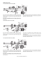
[3] CIRCUIT DIAGRAM AND PARTS LAYOUT
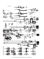
1. CIRCUIT DIAGRAM
Main Unit +24V
Main Unit I/F
JAM Cover Open/
Closed SW
Main Unit +5V
Reverse Sensor
Paper Exit Sensor
Reverse Unit Open/
Closed Sensor
Chassis Cover Open/
Closed Sensor
Mode 5
Document Width
Detection Volume
no-mounting
Tray Sensor
Sub Tray Drawn
Detection Sensor
Sub Tray Folded
Detection Sensor
Set Sensor
Empty Sensor
Registration Sensor
Timing Sensor
AR-CF2 CIRCUIT DIAGRAM AND PARTS LAYOUT / 回路図と部品配置図 3 - 1
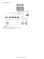
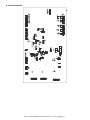
Finisher I/F
Reverse Motor
no-mounting
Horizontal Transport
Motor
no-mounting
no-mounting
Flapper Solenoid
Registration Clutch
no-mounting
Paper Feed Motor
no-mounting
no-mounting
no-mounting
no-mounting
no-mounting
no-mounting
no-mounting
no-mounting
AR-CF2 CIRCUIT DIAGRAM AND PARTS LAYOUT / 回路図と部品配置図 3 - 2
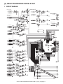
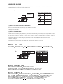
2. PARTS LAYOUT
A. PARTS SURFACE
CN2
No.
1
2
3
4
5
6
Signal Name
H_MOT_*B
H_MOT_B
H_MOT_*A
H_MOT_A
+24V
+24V
CN3
No.
1
2
3
4
5
6
7
Signal Name
N.C.
+24V
+24V
Y_MOT_A
Y_MOT_*A
Y_MOT_B
Y_MOT_*B
CN1
No.
1
2
3
4
5
6
Signal Name
K_MOT_A
+24V
K_MOT_*A
K_MOT_B
+24V
K_MOT_*B
Signal Name
CN4
No.
4
3
2
1
Signal Name
R_CL
+24V
F_SOL
+24V
Signal Name
CN10
No. Signal Name
3 *J_PTH
2 JCK_SW
1 +24V
Signal Name
CN6
No. Signal Name
1 +24V
2 PGND
CN14
No. Signal Name
1 +5V
2 SGND
3 S_SEN
4 +5V
5 SGND
6 EMP_SEN
7 +5V
8 SGND
9 REG_SEN
10 +5V
11 SGND
12 TIM_SEN
13 N.C.
CN15
o. Signal Name
1 P_ST_SW
2 P_MO_SW
3 P_PN_SW
4 P_PN_LED
5 SGND
6 P_MO_LED1
7 P_MO_LED2
8 P_MO_LED3
9 P_MO_LED4
10 P_ST_LED1
11 P_ST_LED2
AR-CF2 CIRCUIT DIAGRAM AND PARTS LAYOUT / 回路図と部品配置図 3 - 3
CN7
No.
7
6
5
4
3
2
1
Signal Name
SGND
+5V
RESET
DSR0
DTR0
RxD0
TxD0
CN9
No.
6
5
4
3
2
1
Signal Name
SGND
RESET
DTR1
DSR1
RxD1
TxD1
B. SOLDER SURFACE
AR-CF2 CIRCUIT DIAGRAM AND PARTS LAYOUT / 回路図と部品配置図 3 - 4
Memo
Memo
LEAD-FREE SOLDER
The PWB’s of this model employs lead-free solder. The “LF” marks indicated on the PWB’s and the Service Manual mean “Lead-Free” solder.
The alphabet following the LF mark shows the kind of lead-free solder.
Example:
<Solder composition code of lead-free solder>
Lead-Free
5mm
Solder composition
code (Refer to the
table at the right.)
a
Solder composition
Solder composition code
Sn-Ag-Cu
a
Sn-Ag-Bi
Sn-Ag-Bi-Cu
b
Sn-Zn-Bi
z
Sn-In-Ag-Bi
i
Sn-Cu-Ni
n
Sn-Ag-Sb
s
Bi-Sn-Ag-P
Bi-Sn-Ag
p
(1) NOTE FOR THE USE OF LEAD-FREE SOLDER THREAD
When repairing a lead-free solder PWB, use lead-free solder thread.
Never use conventional lead solder thread, which may cause a breakdown or an accident.
Since the melting point of lead-free solder thread is about 40°C higher than that of conventional lead solder thread, the use of the exclusive-use
soldering iron is recommendable.
(2) NOTE FOR SOLDERING WORK
Since the melting point of lead-free solder is about 220°C, which is about 40°C higher than that of conventional lead solder, and its soldering capacity is
inferior to conventional one, it is apt to keep the soldering iron in contact with the PWB for longer time. This may cause land separation or may exceed
the heat-resistive temperature of components. Use enough care to separate the soldering iron from the PWB when completion of soldering is
confirmed.
Since lead-free solder includes a greater quantity of tin, the iron tip may corrode easily. Turn ON/OFF the soldering iron power frequently.
If different-kind solder remains on the soldering iron tip, it is melted together with lead-free solder. To avoid this, clean the soldering iron tip after
completion of soldering work.
If the soldering iron tip is discolored black during soldering work, clean and file the tip with steel wool or a fine filer.
!"#$%&'()*+
,-(./012
345
a
5mm
a
b
z
i
n
s
p
6789:;<=
>?@:
AB> 89C1DE)FGHIJGK;L,M ?D @:
>NO>FMP QR STU-VWXY?Z[
NOLP \\R S ABFMP QR STU--];^L_`[Yabc)deLf)DM
LCghijIklmnopqrst^L,`[d=uvwx`bO YVWj@:
yz{L|rU-VWU}~LI YU[)
ZUD@:
U})3L-
-)=`[67U}@:
67b)U}L@`b%`VIM U}@:
CAUTION FOR BATTERY REPLACEMENT
(Danish)
ADVARSEL !
Lithiumbatteri – Eksplosionsfare ved fejlagtig håndtering.
Udskiftning må kun ske med batteri
af samme fabrikat og type.
Levér det brugte batteri tilbage til leverandoren.
(English)
Caution !
Danger of explosion if battery is incorrectly replaced.
Replace only with the same or equivalent type
recommended by the manufacturer.
Dispose of used batteries according to manufacturer’s instructions.
(Finnish)
VAROITUS
Paristo voi räjähtää, jos se on virheellisesti asennettu.
Vaihda paristo ainoastaan laitevalmistajan suosittelemaan
tyyppiin. Hävitä käytetty paristo valmistajan ohjeiden
mukaisesti.
(French)
ATTENTION
Il y a danger d’explosion s’ il y a remplacement incorrect
de la batterie. Remplacer uniquement avec une batterie du
même type ou d’un type équivalent recommandé par
le constructeur.
Mettre au rebut les batteries usagées conformément aux
instructions du fabricant.
(Swedish)
VARNING
Explosionsfara vid felaktigt batteribyte.
Använd samma batterityp eller en ekvivalent
typ som rekommenderas av apparattillverkaren.
Kassera använt batteri enligt fabrikantens
instruktion.
(German)
Achtung
Explosionsgefahr bei Verwendung inkorrekter Batterien.
Als Ersatzbatterien dürfen nur Batterien vom gleichen Typ oder
vom Hersteller empfohlene Batterien verwendet werden.
Entsorgung der gebrauchten Batterien nur nach den vom
Hersteller angegebenen Anweisungen.
CAUTION FOR BATTERY DISPOSAL
(For USA, CANADA)
"BATTERY DISPOSAL"
THIS PRODUCT CONTAINS A LITHIUM PRIMARY
(MANGANESS DIOXIDE) MEMORY BACK-UP BATTERY
THAT MUST BE DISPOSED OF PROPERLY. REMOVE THE
BATTERY FROM THE PRODUCT AND CONTACT YOUR
LOCAL ENVIRONMENTAL AGENCIES FOR INFORMATION
ON RECYCLING AND DISPOSAL OPTIONS.
"TRAITEMENT DES PILES USAGÉES"
CE PRODUIT CONTIENT UNE PILE DE SAUVEGARDE DE
MÉMOIRE LITHIUM PRIMAIRE (DIOXYDE DE MANGANÈSE)
QUI DOIT ÊTRE TRAITÉE CORRECTEMENT. ENLEVEZ LA
PILE DU PRODUIT ET PRENEZ CONTACT AVEC VOTRE
AGENCE ENVIRONNEMENTALE LOCALE POUR DES
INFORMATIONS SUR LES MÉTHODES DE RECYCLAGE ET
DE TRAITEMENT.
All rights reserved.
Printed in Japan.
No part of this publication may be reproduced,
stored in a retrieval system, or transmitted,
in any form or by any means,
electronic; mechanical; photocopying; recording or otherwise
without prior written permission of the publisher.
Trademark acknowledgements
• Microsoft® Windows® operating system is a trademark or copyright of Microsoft
Corporation in the U.S.A. and other countries.
• Windows® 95, Windows® 98, Windows® Me, Windows NT® 4.0, Windows® 2000,
and Windows® XP are trademarks or copyrights of Microsoft Corporation in the
U.S.A. and other countries.
• IBM and PC/AT are trademarks of International Business Machines Corporation.
• Acrobat® Reader Copyright® 1987- 2002 Adobe Systems Incorporated. All rights
reserved. Adobe, the Adobe logo, Acrobat, and the Acrobat logo are trademarks of
Adobe Systems Incorporated.
• All other trademarks and copyrights are the property of their respective owners.
SHARP CORPORATION
Digital Document System Group
Products Quality Assurance Department
Yamatokoriyama, Nara 639-1186, Japan
2003 November Printed in Japan