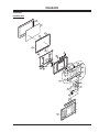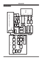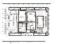
1
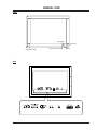
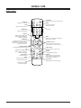
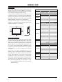
SERVICE MANUAL Model Series: P60W26 Product Type: Chassis: Manual Series: Manual Part #: Model Line: Product Year: Plasma HDTV NP-00KA/B PV154 923-03493 E 2002 CONTENTS Safety .......................................................... 2 Servicing/Troublshooting ............................... 4 Model Part Lists .......................................... 12 Exploded Views ........................................... 13 Schematics ................................................. 32 Published July 2002 by Technical Publications Zenith Electronics Corporation 201 James Record Road Huntsville, Alabama 35824-1513 Printed in U.S.A. Copyright 2002 by Zenith Electronics Corporation PRODUCT SAFETY IMPORTANT SAFETY NOTICE TIPS ON PROPER INSTALLATION This manual was prepared for use only by properly trained audio-visual service technicians. 1. Never install any receiver in a closed-in recess, cubbyhole, or closely fitting shelf space over, or close to, a heat duct, or in the path of heated air flow. 2. Avoid conditions of high humidity such as: outdoor patio installations where dew is a factor, near steam radiators where steam leakage is a factor, etc. 3. Avoid placement where draperies may obstruct venting. The customer should also avoid the use of decorative scarves or other coverings that might obstruct ventilation. 4. Wall- and shelf-mounted installations using a commercial mounting kit must follow the factory-approved mounting instructions. A product mounted to a shelf or platform must retain its original feet (or the equivalent thickness in spacers) to provide adequate air flow across the bottom. Bolts or screws used for fasteners must not touch any parts or wiring. Perform leakage tests on customized installations. 5. Caution customers against mounting a product on a sloping shelf or in a tilted position, unless the receiver is properly secured. 6. A product on a roll-about cart should be stable in its mounting to the cart. Caution the customer on the hazards of trying to roll a cart with small casters across thresholds or deep pile carpets. 7. Caution customers against using a cart or stand that has not been listed by Underwriters Laboratories, Inc. for use with its specific model of television receiver or generically approved for use with TVs of the same or larger screen size. 8. Caution customers against using extension cords. Explain that a forest of extensions, sprouting from a single outlet, can lead to disastrous consequences to home and family. When servicing this product, under no circumstances should the original design be modified or altered without permission from Zenith Electronics Corporation. All components should be replaced only with types identical to those in the original circuit and their physical location, wiring and lead dress must conform to original layout upon completion of repairs. Special components are also used to prevent x-radiation, shock and fire hazard. These components are indicated by the letter “x” included in their component designators and are required to maintain safe performance. No deviations are allowed without prior approval by Zenith Electronics Corporation. Circuit diagrams may occasionally differ from the actual circuit used. This way, implementation of the latest safety and performance improvement changes into the set is not delayed until the new service literature is printed. CAUTION: Do not attempt to modify this product in any way. Never perform customized installations without manufacturer’s approval. Unauthorized modifications will not only void the warranty, but may lead to property damage or user injury. Service work should be performed only after you are thoroughly familiar with these safety checks and servicing guidelines. GRAPHIC SYMBOLS The exclamation point within an equilateral triangle is intended to alert the service personnel to important safety information in the service literature. The lightning flash with arrowhead symbol within an equilateral triangle is intended to alert the service personnel to the presence of noninsulated “dangerous voltage” that may be of sufficient magnitude to constitute a risk of electric shock. The pictorial representation of a fuse and its rating within an equilateral triangle is intended to convey to the service personnel the following fuse replacement caution notice: CAUTION: FOR CONTINUED PROTECTION AGAINST RISK OF FIRE, REPLACE ALL FUSES WITH THE SAME TYPE AND RATING AS MARKED NEAR EACH FUSE. SERVICE INFORMATION While servicing, use an isolation transformer for protection from AC line shock. After the original service problem has been corrected, make a check of the following: FIRE AND SHOCK HAZARD 1. 2. 3. 4. 5. 6. Be sure that all components are positioned to avoid a possibility of adjacent component shorts. This is especially important on items transported to and from the repair shop. Verify that all protective devices such as insulators, barriers, covers, shields, strain reliefs, power supply cords, and other hardware have been reinstalled per the original design. Be sure that the safety purpose of the polarized line plug has not been defeated. Soldering must be inspected to discover possible cold solder joints, solder splashes, or sharp solder points. Be certain to remove all loose foreign particles. Check for physical evidence of damage or deterioration to parts and components, for frayed leads or damaged insulation (including the AC cord), and replace if necessary. No lead or component should touch a receiving tube or a resistor rated at 1 watt or more. Lead tension around protruding metal surfaces must be avoided. After reassembly of the set, always perform an AC leakage test on all exposed metallic parts of the cabinet (the channel selector knobs, antenna terminals, handle and screws) to be sure that set is safe to operate without danger of electrical shock. DO NOT USE A LINE ISOLATION TRANSFORMER DURING THIS TEST. Use an AC voltmeter having 5000 ohms per volt or more sensitivity in the following manner: Connect a 1500 ohm, 10 watt resistor, paralleled by a .15 mfd 150V AC type capacitor between a known good earth ground water pipe, conduit, etc.) and the exposed metallic parts, one at a time. Measure the AC voltage across the combination of 1500 ohm resistor and .15 mfd capacitor. Reverse the AC plug by using a non-polarized adaptor and repeat AC voltage measurements for each exposed metallic part. Voltage measured must not exceed 0.75 volts RMS. This corresponds to 0.5 milliamp AC. Any value exceeding this limit constitutes a potential shock hazard and must be corrected immediately. PV154 - 923-03493 2 P60W26 - SAFETY TABLE OF CONTENTS IMPORTANT SAFETY NOTICE .................................. 2 TABLE OF CONTENTS ............................................ 3 GENERAL INFO ................................................... 5 FEATURES ..................................................... 5 SPECIFICATIONS ............................................. 5 FRONT .......................................................... 7 BACK ........................................................... 7 REMOTE CONTROL ........................................... 8 INSTALLATION ................................................ 9 CONNECTING A COMPUTER ................................ 9 USER MENUS ................................................... 10 APC (AUTO PICTURE CONTROL) ....................... 10 DRP (DIGITAL REALITY PICTURE) .................... 10 PICTURE SETTINGS ....................................... 10 MENU LANGUAGE SETUP ................................ 10 SLEEP TIMER ............................................... 10 STILL FUNCTION ........................................... 10 SCREEN ....................................................... 11 TRANSPARENCY............................................. 11 SET ID ........................................................ 11 COLOR TEMPERATURE .................................... 11 DASP (DIGITAL AUTO SOUND PROCESSING) ........ 11 AVL (AUTO VOLUME LEVELER) ......................... 11 ADJUSTING SOUND ....................................... 11 PICTURE FORMAT ......................................... 12 ADJUSTMENT INSTRUCTIONS ............................... 13 POWER PCB ASSY VOLTAGE ADJUSTMENT ........... 13 ADJUSTMENT WHITE BALANCE ......................... 13 SERVICE MENU ............................................. 15 TROUBLE SHOOTING NO VIDEO ........................ 16 TROUBLE SHOOTING NO POWER ....................... 16 TROUBLE SHOOTING ABNORMAL PICTURE .......... 17 TROUBLE SHOOTING NO SOUNDS ...................... 17 MODEL PARTS .................................................. 18 P60W26 ..................................................... 18 DIAGRAMS ...................................................... 19 EXPLODED VIEW ........................................... 19 POWER BLOCK DIAGRAM ................................ 20 VSC BLOCK DIAGRAM ..................................... 21 SCHEMATICS .................................................... 22 INTERCONNECT ............................................. 22 CIRUIT ....................................................... 23 CIRUIT ....................................................... 24 CIRUIT ....................................................... 25 CIRUIT ....................................................... 26 MAIN & POWER PCB LAYOUT ........................... 27 SMPS PCB LAYOUT ........................................ 28 OTHER PCB LAYOUTS ..................................... 29 PV154 - 923-03493 3 P60W26 - SERVICING -4- GENERAL INFO GENERAL INFO SPEAKER STAND H x W x D ............................... 8.70" x 8.60" x 8.70" Weight ........................................................ 4 lbs. UPC Code ...................................... 04464200552 8 FEATURES 60" PLASMA HDTV MONITOR Groundbreaking display technology delivers superior image clarity, color, and brightness in large-format televisions that are less than 4" thick ACCESSORIES 15-Wire RGB Cable ............................................. Yes R/L Audio Cable (w/Speaker) .............................. Yes Power Cord ....................................................... Yes (Optional) Table/Desk Mount/Pedestal ................................. Yes Wall Mount ....................................................... Yes Integrated Power Supply .................................... Yes Anti Reflection Screen ...... Included DPD Screen Filter AC-Line ......................................................... 120v Speakers .......................................................... Yes 1280 X 720P RESOLUTION High resolution format produces extremely detailed imagery 550:1 CONTRAST RATIO Extremely sharp contrast between light and dark images 500 CD/M2 HIGH BRIGHTNESS Renders an incredibly bright picture, even in well-lit areas ASPECT RATIO CORRECTION Intelligent resizing of video and computer images to 16:9 widescreen or 4:3 conventional formats. REMOTE CONTROL Transmitter ....................................................... Yes Model Number ............................................. SC3261 Transmitter Finish ............................. Brushed Silver INTELLIGENT IMAGE SCALING Faroudja/Sage scan converter seamlessly converts TV video data to PC formats without distortion or cropping images in either 4:3 or 16:9. INPUTS RS-232 Controls and NTSC, HD, VGA, SVGA, XGA, and SXGA inputs Compatible with DVD players, VCRs, computers, digital broadcasting, multimedia, and traditional video sources. SERVICE/LIMITED WARRANTY Warranty: Parts/Labor. ......................... 1 Year/1 Year MTBF (Approx.) ...................................... 30K Hours Life Expectancy (Approx.) ....................... 30K Hours UPC Code ........................................ 4464200402 6 SPECIFICATIONS CABINET DIMENSIONS H x W x D ............................ 57.30" x 34.80"x 3.90" Weight .................................................. 154.3 lbs. UPC Code ...................................... 04464200412 5 Finish .............................................. Brushed Silver Cabinet Style ......................................... Slim Frame Power Consumption ............ 650W (Max Audio 700W) Power Source ......................................... 120v 60Hz VIDEO Screen Size ...................................................... 60" Resolution Display ............................... 1280 x 720p Pixel Pitch ............................ 0.343 (H) x 1.032 (V) Aspect Ratio ................................... 16:9, 4:3 Zoom Brightness ............................................ 500 cd/m2 Contrast Ratio .............................................. 550:1 Twin Picture, PIP .............................................. Yes Viewing Angle ................................................ 160º Format Conversion ........... Intelligent Image Scanning Aspect Ratio Correction ..................................... Yes Scan Converter ................................. Faroudja, Sage Color Temperature ................................ 8,000k Fixed Contrast ........................................................... Yes Brightness/Sharpness ......................................... Yes Tint ................................................................. Yes CABINET W/PACKING H x W x D ......................... 45.30" x 36.50" x 23.00" Weight .................................................... 183 lbs. CABINET STAND H x W x D ............................... 45.7" x 15.5" x 16.3" Weight ................................................... 66.8 lbs. SPEAKER DIMENSIONS H x W x D ............................. 5.30" x 34.80" x 3.90" Weight ..................................................... 5.5 lbs. UPC Code ...................................... 04464200542 9 PV154 - 923-03493 DISPLAY Display Frequency. ..... 15.73-68kHz (H), 50-80kHz (V) PLE ................................................................. Yes Displayable Colors ....................................... 16.77M 5 P60W26 - SERVICING GENERAL INFO Color Gradation Filter ......................................... Yes Input Signal ............ NTSC, HD, VGA, SVGA, XGA, SXGA Display modes ........................... Normal, Wide, Zoom Side Panels (Gray Bars for 4:3 Display) .................. Yes AUDIO Mono/Stereo/MTS/SAP ......................... Mono/Stereo Bass/Treble/Balance ........................................... Yes Total Audio (Watts) .......................... 20W (2 x 10W) Speaker Size (Dimensions) ....... 135mm/964mm/99mm Subwoofer ........................................................ No SPECIAL FEATURES Acoustic Noise .................................................. Yes Picture In Picture (PIP) ..................................... Yes Multi-lingual Menus ..... English/Spanish/French/Portuguese/Korean 1 Level Mute ..................................................... Yes Shock Absorbing Glass Damper ........... Yes, Tilt to 20º RS232 Control ................................................... Yes Detachable AV Terminal ....................................... Yes Auto-Power On .................................................. Yes Discrete Power Off ............................................. Yes Last Source On .................................................. Yes OPERATING ENVIRONMENTS Temperature Range .............................. -20ºC – 60ºC Humidity Range ...................................... 20 – 80% Altitude .................................................... 2,000m Operating Temperature ........................... -5ºC – 45ºC UPC Code ...................................... 04464200562 7 PV154 - 923-03493 6 P60W26 - SERVICING GENERAL INFO FRONT Input Select Sub Power INPUT VOLUME SELECT ON/OFF Remote Control Sensor Main power button Volume BACK S-Video Y Y PV154 - 923-03493 PB PR PB PR ½ (+) Audio Inputs 7 ( ) ( ) AC INPUT (+) S-Video (+) ( ) ( ) (+) P60W26 - SERVICING GENERAL INFO REMOTE CONTROL POWER ON POWER ON Toggles the on on and off. SYSTEM OFF SLEEP MUTE * MUTE Toggles the sound on and off. 1 3 2 VIDEO PC Toggles through available video inputs. Composite, Component, RGB-PC, & RGB-DTV 4 5 7 8 VIDEO/PC THUMBSTICK Navigates the on-screen menus and adjusts system settings and preferences. Use the arrows to navigate menus and press the center to select. INPUT SELECT Auto Picture Control Turns sound Off and On while picture remains. * 9 MENU 0 MENU Displays menus and advances through the different menus available. up vol enter vol TWIN PICTURE PIP INPUT SELECT RATIO CHANNEL (Up/Down) Selects next channel in TV’s memory or scrolls up/down in GUIDE Plus+ Gold. down FREEZE POSITION EASY SOUND APC RATIO Use the ratio button to select the desired picture format. TWIN PICTURE Allows 2 sources to be shown on the at one time. FREEZE The image displayed is frozen. POSITION While in PIP mode, each press of the position button will change the position of the sub picture on the screen. EASY SOUND Toggles through preset sound settings. APC Automatic Picture Control. Preset picture settings. PV154 - 923-03493 SLEEP 6 VOLUME UP/DOWN Increases/decreases the sound level. PIP Toggles through available video inputs. Composite, Component, RGB-PC, & RGB-DTV Toggles the current component power on/off. <no function> NUMBER PAD Selects channels directly. SYSTEM OFF 8 P60W26 - SERVICING GENERAL INFO INSTALLATION It is recommended that this product only be used at an altitude of less than 6562 feet (2000m) to get the best quality picture and sound. This plasma display is designed to be mounted horizontally (wide viewing). - Your P42W22, P42W22B models (Monitor) can be installed on a wall or on a desktop pedestal. Wall mount and stands are optional and not supplied with the monitor. (For further information, refer to the optional Tilt/Wall Mounting Bracket Installation and Setup Guide.) Install this monitor only in a location where adequate ventilation is available. Minimum allowable clearances for adequate ventilation are show below. 640x350 720x400 640x480 1.18inch 4inch 4inch P60W26 Computer Video Horizontal Vertical Resolution Frequency (KHz) Frequency (KHz) 4inch 800x600 4inch CONNECTING A COMPUTER Connect the video output of the PC to the Monitor RGBPC INPUT (VGA/SVGA/XGA) RGB-DTV INPUT (480p/720p/ 1080i) using a standard shielded VGA cable. Connect the audio out from the PC to the Audio jacks on the Monitor (Audio cables are not included with the Monitor). Set the computer video output to SXGA (1280x1024) or lower resolution. If the video output of the PC is not compatible with the Monitor, no picture will appear on the Monitor (see chart). Turn the PC on and press the ON/OFF button on the Monitor, to go to standby mode. Then press the button on the Monitor or press power on on the remote control. Use the video/pc button on the remote control to select the RGB source. To set up this monitor in a PC Windows environment, select Normal, Standard, or Default monitor. This monitor does not support Plug and Play function. 832x624 1024x768 1280x720 1152x864 1152x870 1280x960 1280x1024 31.468 37.861 31.469 37.927 31.469 35.000 37.861 37.500 43.269 45.913 53.011 64.062 35.156 37.879 48.077 46.875 53.674 56.000 64.016 49.725 48.363 56.476 60.023 68.677 52.400 54.348 63.995 67.500 77.487 68.681 60.000 75.000 63.981 79.976 70.090 85.080 70.080 85.030 59.940 66.660 72.800 75.000 85.000 90.030 100.040 120.000 56.250 60.310 72.180 75.000 85.060 90.000 100.000 74.550 60.000 70.060 75.020 84.990 69.980 60.050 70.010 75.000 85.050 75.060 60.000 75.000 60.020 75.020 Note: Avoid prolonged display of a still image, as it may cause a permanent image to remain even after you change the image. PV154 - 923-03493 9 P60W26 - SERVICING USER MENUS USER MENUS APC (AUTO PICTURE CONTROL) APC is used to set the Monitor for the best picture appearance. Press the apc button. Use the APC or volume buttons to select the picture appearance setup. APC is not available in RGB or PIP mode. Each press of vol buttons selects the menu option. Available options are select CLEAR, SOFT or USER. User refers to manual adjustments made to the picture menu options. SPECIAL LANGUAGE ARC SCREEN TRANSPARENCY PIP SET ID COLOR TEMP. ENGLISH ESPAÑOL FRANÇAIS SLEEP TIMER Sleep Timer turns the set off after a preset time expires. Use the sleep button to set a sleep time. Each time you press the sleep button, the time setting time changes as follows: DRP (DIGITAL REALITY PICTURE) DRP improves image outlines in dark screens. This feature works in both video and component 480i modes. Use the up/down button to select DRP and then press the volume up button. Use the up/down button to select CLEAR or SOFT. Press the enter button to exit. --- 10 20 30 120 90 60 24 0 180 PICTURE APC DRP CONTRAST BRIGHTNESS COLOR TINT SHARPNESS 100 50 50 0 50 CLEAR SOFT SLEEP PICTURE SETTINGS Adjusts BRIGHTNESS, COLOR, TINT, and SHARPNESS in the same way. Use the volume buttons to make appropriate adjustments and then press the enter button. Use the up/down buttons to select other menu options. To cancel sleep time setting, press the sleep or volume up/down button repeatedly to select. SLEEP 1 will be displayed one minute before the set is due to turn off. Tips • When the sleep time you want is displayed on the screen, don’t press the sleep button. After 20 seconds, the screen display disappears and sleep time is set. • To check remaining sleep time after setting, press the sleep or enter button just once. • If the set is turned off after setting the sleep timer, the setting is erased. The sleep timer will then have to be set again. PICTURE APC DRP CONTRAST BRIGHTNESS COLOR TINT SHARPNESS 100 50 50 0 50 Note: PIP picture settings are not adjustable. MENU LANGUAGE SETUP Press the menu button and then use the volume up/ down buttons to select the SPECIAL menu. Use the volume up/down button to select LANGUAGE and then press the volume up button. Use the volume up/down button to select the desired language. Press the enter button to exit. PV154 - 923-03493 30 STILL FUNCTION Use with the A/V or COMPONENT video input sources. Press the freeze button. The image displayed is frozen (stilled). In PIP mode, the sub (inset) picture is frozen. To return to normal viewing, press the freeze button again. This feature isn’t available for RGB input source. 10 P60W26 - SERVICING USER MENUS Tips • If a still picture is on the screen for more than 5 minutes, the image becomes dark. This is a protective feature designed to lessen the chance of a ghost image burning onto the monitor screen. If another function is activated, normal screen brightness is restored. This feature isn’t available for RGB input source. SPECIAL LANGUAGE ARC SCREEN TRANSPARENCY PIP SET ID COLOR TEMP. SCREEN Use this option to correct trembling or instability of a videotape image. Use the volume buttons to select SCREEN and then press the volume up button. Use the volume buttons to select TV or VCR. Select the VCR option if watching a VCR. Select the TV option for other equipment. Each time you press the up/down button you toggle between TV and VCR. Press the enter button to exit. RED LANGUAGE RED CAPTION GREEN AUTO OFF BLUE SCREEN RGB-OUTPUT FL A T SOUND 50 50 50 0 G G G G 0 G G G SPO RT S USER C I N EMA MUSI C AVL (AUTO VOLUME LEVELER) This feature maintains an equal volume level, even when changing channels. Use the up/down button to select AVL and then press the volume up button. Use the up/ down button to select ON or OFF. Press the enter button to exit. Use the volume buttons to adjust OSD transparency. The TRANSPARENCY adjustment range is 1 ~ 4. Press the enter button to exit. SET ID Use Set ID to specify a monitor identification number. Press the menu button and then use the up/down button to select the SPECIAL menu. Press the vol (G) button. Use the up/down buttons to select SET ID and then press the volume up button. Use the volume button to adjust SET ID to choose a desired monitor ID number. The adjustment range for SET ID is 1 ~ 99. SOUND DASP AVL TREBLE BASS BALANCE 50 50 0 ON OFF Use the volume button to make appropriate adjustments and then press the enter button. The adjustment range of RED, GREEN, and BLUE is -5 to +5. COLOR TEMPERATURE Press the up/down button to select COLOR TEMP. and then press the volume up button. Press the up/down button to select RED and then press the volume up button (to adjust RED setting). Adjust GREEN and BLUE in the same way. PV154 - 923-03493 G DASP (DIGITAL AUTO SOUND PROCESSING) Automatic sound adjustment setting. The set automatically selects the appropriate audio tone levels based on the program content. Press the easy sound button. Use the easy sound or volume buttons to select a sound setup. Each press of easy sound or vol buttons changes menu option as shown below. TRANSPARENCY To make the menu backgrounds clear or opaque. Press the menu button and then use the up/down button to select SPECIAL menu. Use the up/down button to select TRANSPARENCY and then press the volume up button. DASP AVL TREBLE BASS BALANCE TO SET ADJUSTING SOUND Manual sound adjustments. Use the up/down buttons to select TREBLE and then press the volume up button. Adjust BASS and BALANCE in the same way. Use the volume buttons to make appropriate adjustments and then press the enter button to exit. Use the up/down buttons to select other options. 11 P60W26 - SERVICING USER MENUS PICTURE FORMAT Use the ratio button to select the desired picture format. Each time you press ratio or volume buttons, you cycle through 16:9, 4:3, and ZOOM. With RGB-PC as the source, you can select either 16:9 or 4:3 screen aspect ratios. With the RGB-DTV source, you can select the 16:9 screen aspect ratio. If 4:3 mode is used for a long time, the outline of the image may remain on the screen after you change to the 16:9 screen aspect ratio. Don’t display 4:3 picture format for more than 10 hours continuously. You can also select 16:9, 4:3, or ZOOM options using the SPECIAL menu. ARC F 16 : 9 G 16:9 ARC F 4:3 G 4:3 ARC PV154 - 923-03493 F ZOOM G 12 P60W26 - SERVICING SERVICING ADJUSTMENT INSTRUCTIONS These instructions are applied to all of the PDP monitor, NP-00KB. Because this is not a hot chassis, it is not necessary to use an isolation transformer. However, the use of isolation transformer will help protect test instruments. Adjustment must be done in the correct order. If there is no specific designation, the adjustment must be performed at 25±5oC of temperature and 65±10% of relative humidity. The input voltage of the receiver must maintain 110~240V, 50/60Hz while adjusting. Operate the receiver for about 15 minutes prior to the adjustment with 100% white pattern (06CH). (Or white condition in HEAT-RUN mode) Enter into HEAT-RUN mode. Select the 2 W/B by pressing ADJ button on Remote Control for adjustment. And press the VOL + button. Press the VOL + button in HEAT-RUN. (OSD display HEAT-RUN WHITE and screen display 100% full WHITE PATTERN). Set is activated HEAT-RUN without signal generator in this mode. Single color pattern of HEAT-RUN mode uses to check the PANEL. (RED/BLUE/ GREEN) Caution: If you turn on a still screen more than 20 minutes, an afterinage may occur in the black level part of the screen. <F ig 1> C onnection D iagram of Power Adjus tment for M eas uring ADJUSTMENT WHITE BALANCE REQUIRED EQUIPMENT Color analyzer(CA-100 or same production) TYPE; CA-100 POWER PCB ASSY VOLTAGE ADJUSTMENT After replacing the PDP Module or Power Board, adjust the Power PCB Assy voltage. TEST EQUIPMENT D.M.M 1EA 75±6cd/m2 CVBS Signal Input 15±3cd/m2 PDP MONITOR Window MSTG-5200 CONNECTION DIAGRAM Refer to Fig 1. <Fig 2> Connection Diagram of Automatic Adjustment ADJUSTMENT METHOD WHITE BALANCE ADJUSTMENT Operate the Zero-calibration of the CAÑ100, then place the sensor to the PDP module surface when you adjust. Manual adjustment is also possible by the following sequence. (1) Select the WHITE PATTERN of HEAT RUN mode by pressing the ADJ button on Remote Control for adjustment, then operate HEAT RUN more than 15 minutes. (2) Supply 10 step gray scale bar signal in pattern generater. (A/V Input) PFC ADJUSTMENT After displaying the 100% white pattern (HEAT-RUN). Connect TP PFC+ and TP PFC-(GND) to D.M.M. Turning VR801, adjust to 380V(±1V). VA ADJUSMENT Connect pin 1 of P814 to (+) jack of D.M.M. After turning the VR803(Va Adj), voltage of D.M.M adjustment as same as Va voltage which on label of panel Left/Top.(Deviation : ±0.5V). VS ADJUSTMENT Connect pin 9 of P803 to (+) jack of D.M.M. After turning the VR804(Vs Adj), voltage of D.M.M adjust as same as Vs voltage which indicated on label of panel Left/Top (Deviation : ±0.5V). PV154 - 923-03493 13 P60W26 - SERVICING SERVICING (3) To adjust Low Light, place the sensor to the ninth pattern (Dark). Then select the W/B by pressing the ADJ button on the remote or adjustment and press the VOL + button to enter Adjustment Mode. Select the G cut and B cut, press the VOL +/- Key and adjust it until color coordination becomes (R cut fixation): color coordination : X=0.283±0.005, Y=0.295±0.005 color temperature : 9,600cK ± 500cK (4) To adjust High Light, place the sensor on the second pattern (White), select the W/B by pressing ADJ button on Remote Control for adjustment and press the VOL + button enter Adjustment Mode. After select the R GAIN and G GAIN, press the VOL +/- Key and adjust it until color coordination becomes (B GAIN fixation) color coordination : X=0.283±0.005, Y=0.295±0.005 color temperature : 9,600cK ± 500cK (5) Confirm the result of the High Light adjustment. If the deviation of High Light occurs, operate the adjustment of Low Light and High Light again. (6) Exit adjustment mode using Enter button. PV154 - 923-03493 14 P60W26 - SERVICING SERVICING SERVICE MENU Service Menu Adjustments for Plasma Display Once the Main Video Scan Converter module is installed, the unit will power on as soon as A/C is applied. The EEPROM data will be set to Factory default values. The following charts and instructions will allow you to set access the service menu and make any necessary adjustments during the repair and installation of the PDP. Adjustments must be done in both NTSC/PC and DTV Modes If the unit will power on prior to the replacement of this Module and the menus can be accessed it recommended that the servicer access the service menu and record the data from the original EEPROM. The Service Remote, which is provided with the service kit, must be used to access the service menu. ADJUSTMENTS 1. The following menu can be accesed with the unit off by pressing (POWER ON). 2. Press (ADJ) key. 3. Use the (UP and DOWN) keys to select the sub-menu you wish too access. 4. Press the (RIGHT) adjust key to access the menu. 5. The (UP and DOWN) will again access the line item you wish to adjust. 6. The (RIGHT and LEFT) keys will change the setting. 7. ENTER will record the new settings. Equipment Needed: 1 2 3 4 NTSC Pattern Generator DTV Pattern Generator. INITIAL SETTINGS 1. 2. 3. 4. 5. 6. 7. Press (POWER ON) key Press (ADJ) key. Scroll down to (OPTION) item. Press right arrow to enter (OPTION) menu. Scroll down to (REMOCON) item. Use (RIGHT) and (LEFT) keys to change to ZENITH. Press (ENTER) to lock changes in memory. Option System Remocon Language 50/60 1 NTSC NEC Korean 60 PV154 - 923-03493 2 NTSC Zenith ENG 60 3 3Sys NEC Portugal 60 4 3Sys NEC Espanol 60 ADJ W/B CXA2101 ADJ OPTION 2 PHASE H-PHASE V-PHASE EEPROM INIT 30 195 34 HEAT RUN AUTO CUTOFF R-CUT G-CUT B-CUT R-GAIN G-GAIN B-GAIN OFF 1 22 11 23 14 13 13 CXA2101 0 BCUT 1 RCUT 2 R-GAIN 3 G-GAIN 4 B-GAIN 5 S CONTRAST 6 S BRIGHT 7 S-COL 8 S-TINT 9 S-SHARP 10 CTI-LEVEL 11 R-Y/R 12 G-Y/R 13 R-Y/B 14 G-Y/B 15 GAMMA 16 LTI-LEV 17 PRE/OVER 18 DC-TRAN 19 D-PIC 20 V-TC 21 H-WIDTH 22 D-COL 23 HD-TC 24 SHP-FO 5 3Sys NEC ENG 60 15 7 7 0 0 0 0 44 7 7 3 0 6 10 9 5 7 0 1 0 2 1 3 1 0 1 P60W26 - SERVICING SERVICING No Video Nothing output of image. Check Input of AC. (85~225V) Abnormal Connect plug with the set. Normal Check ST-BY LED ON Main S/W ON. Abnormal Check AC Line Fuse. Normal Check LED YELLOW Sub S/W ON. Abnormal Check OPEN with PFC R8301, R8302, R8303. Abnormal Replace R8301, R8302, R8303. Normal Abnormal Check OPEN with R8538, R8539, 8540. Normal Check normal operation with VS, VA PACK. Check operation of FAN. Check output of 5V MONI, 5V CTL. Normal Check CRTL Pack VS On. Abnormal Replace CTRL PACK. Normal Check a connective condition and various connector. No Power Check a connective condition of power cable. PV154 - 923-03493 Check voltage of sound terminal. Check Open with F8811 Fuse. 16 Check connection line of speaker. P60W26 - SERVICING SERVICING Abnormal Picture Abnormal Picture Abnormal Check JAGASM IC501 Input PC signal. Normal Check CXA2101 IC203 Check SII150 IC901 Normal Check ADV7123 IC406 Check cable of pin 21 P901 Normal Check FLI2220 IC404 Normal Check FLI2200 IC403 Normal Check VPC3230 IC201 Normal Check Input jack & Connector. No Sound Check connector speaker to set. PV154 - 923-03493 Check MSP3401 IC601 17 Check LA4282 IC603 Check Input Jack. P60W26 - SERVICING PARTS MODEL PARTS All FC models are module level repair only. Parts contact information is below. Voice: 1-888-3-ZENITH Fax: 1-888-6-ZENITH Mail: Zenith National Parts 201 James Record Road Huntsville, AL 35824-1513 580 590 600 610 620 630 6871VSMB46A 6871VSM668A 6871VSM669A 6871VSM670A 6871VSM676B 6871VSMC90A 640 6871VSMB57A PCB ASSEMBLY,SUB VER.2 PFC PACK PCB ASSEMBLY,POWER VA M/I PCB ASSEMBLY,POWER VS M/I PCB ASSEMBLY,POWER CONTROL PCB ASSEMBLY,SUB SIDE A/V PCB ASSEMBLY,A/V VER2 INTERFACE BD PCB ASSEMBLY,SUB VER.2 FAN CONTRO P60W26 No. 101 200 201 202 203 204 205 206 207 208 209 210 211 212 213 214 300 Part No. 5900V08004A 6348Q-B032D 6871QRH015B 6871QTH021A 6871QZH018B 6871QTH022A 6871QRH014B 6871QXH009B 6871QLH016B 6871QDH028B 6871QYH017B 6871QDH027B 6871QLH017B 6871QXH008B 6871QCH012B 6871QPH001B 3091V00287E 301 302 4980V00142B 4980V00142A 303 4980V00143B 304 4980V00143A 305 3790V00267B 306 310 330 331 4980V00141A 5020V00437A 5020V00436A 3141VSN122B 400 3809V00280C 401 520 3300V00067P 6871VMM992A 530 540 550 560 6871VPM992A 6871VPM991A 6871VSM677A 3141VSN195A PV154 - 923-03493 Description FAN,DC F8025L12B2-RG 80MM 1 PDP,60 16:9 1280*720 FOR DND INTE PCB ASSEMBLY,XRRT ASSY 60HD4(X PCB ASSEMBLY,ZCNT ASSY 60HD4 2 PCB ASSEMBLY,ZSUS ASSY 60HD4(Z_ PCB ASSEMBLY,ZCNT ASSY 60HD4 2L PCB ASSEMBLY,XRRT ASSY 60HD4(X PCB ASSEMBLY,XRCT ASSY 60HD4 4L PCB ASSEMBLY,XRLT ASSY 60HD4(X PCB ASSEMBLY,YDRV ASSY 60HD4 4L PCB ASSEMBLY,YSUS ASSY 60HD4 4L PCB ASSEMBLY,YDRV ASSY 60HD4 (T PCB ASSEMBLY,XRLT ASSY 60HD4(X PCB ASSEMBLY,XRCT ASSY 4LAYER(T PCB ASSEMBLY,CTRL ASSY 60HD4 1C PCB ASSEMBLY,DCDC ASSY 60HD4 CABINET ASSY,MU-60PZ10 ZENITH LIGHT SILVER SUPPORTER,FILTER TOP LEFT FD-60X3 SUPPORTER,FILTER TOP RIGHT FD60X3 SUPPORTER,FILTER BOTTOM LEFT FD60X3 SUPPORTER,FILTER BOTTOM RIGHT FD60X3 WINDOW,H04PR-LGE60-02 FD60X3R FIBER M SUPPORTER,FILTER R/LEFT FD-60X3 BUTTON,4KEY FD-60X3 BUTTON,FD-60X3 CHASSIS ASSEMBLY,SUB POWER SWITCH BACK COVER ASSEMBLY,MN-60PZ12 3808V00203A PLATE,REAR A/V MU-60PZ11 PCB ASSEMBLY,MAIN MAIN VER.2 VSC N PCB ASSEMBLY,SMPS PFC V.2 PCB ASSEMBLY,SMPS POWER V.2 PCB ASSEMBLY,CONT CONTROL CHASSIS ASSEMBLY,SUB LINE FILTER ASSY 18 P60W26 - PARTS DIAGRAMS DIAGRAMS EXPLODED VIEW 300 305 301 302 306 303 101 304 640 201 331 620 202 212 560 203 211 550 310 213 330 204 210 206 209 205 214 208 200 207 600 590 540 610 530 520 580 630 401 400 PV154 - 923-03493 19 P60W26 - DIAGRAMS ~ PV154 - 923-03493 POWER CONTROL 20 PFC 380V Power Switching FET PFC INDUCTOR UC 3854 HIGH POWER FACTOR PREREGULATOR PFC Pack Aux. 16V St-by 5V Auxillary Trans ST-BY Trans TINY 255P TINY 255P Fly Wheel DIODE UC 3863 Resonant power supply mode IR 2113S High speed power FET driver VS Pack UC 3863 Resonant power supply mode IR 2113S High speed power FET driver VA Pack Panel Ctl 5V Panel Drive 5V VSC 16V Sound 30V VSC 6V VSC 12V Power FET 2sk2837 Power FET 2sk2837 VS 170-185 VA 72-80 DC-DC Step down Regulator SI-8050S Step down Regulator SI-8120S SOUND PANEL SUSTAIN ADRESS LOGIC DRIVE FAN VSC VIDEO SCAN CONVERTER Zero Current Resonant Mode STRF6668B + MULTI TRANS FLY BACK MODE CTL Pack 5V moni RECTIFIER RL on Rush CTL RECTIFIER VS on RUSH CONTROL EMI FILTER P F C EPROM DIAGRAMS POWER BLOCK DIAGRAM VS on P60W26 - DIAGRAMS PV154 - 923-03493 Control (RS232C) YCbCr/ YPbPr CVBS Y/C 21 L R AUDIO AMP LA4282 (L & R) AUDIO AUDIO SWITCH (LA7222) COLOR DECODER (VPC3230D) 5 YUV 16 4 H/V/ FIELD/ LLC1 2 H MEMORY (4M-BYTE) DEINTERLACE (FLI2200) Rx,Tx RGBHV H/V RGB 2 30 16 YUV 30 ROM (AT29C010) (74HCT373) RGBHV DAC (ADV7123) 5 RGB Y,Pb,Pr(MNT) 3 ENHANCER (FLI2220) 5 H/V/CLK/ HBLK/VBLK RGB 3 SCALER (JAGASM) MEMORY (8M-BYTE) 48 MICOM 2 H/V Clamp V H 2 H/V TMDS TX (SII150) EEPROM X2416P PORT EXP (M62320X4) COLOR CONTROL & VIDEO SWITCH (CXA2101Q) RGBHV 5 H/V/DE/CLK RGB 4 Digital Line EPLD (GEN. CLAMP) Analog Line 8 21P DIAGRAMS VSC BLOCK DIAGRAM P60W26 - DIAGRAMS 2 1 3 4 5 6 7 8 9 G N/C GND 15V GND 5V N/C GND 15V GND 5V N/C GND 15V GND 5V P15 P1003B 5VA 5VA 5VA 5VA P1807 TP5 (GN) TP6 (VA) CN8 5V GND 15V GND N/C 5V GND 15V GND N/C N/C PFC+ PFC+ + CN2 TP2 (GND) N/C PFC+ PFC+ TP1 (380V) TP4 (VS) TP3 ( GN) P21 VS ADJ N/C 5V NOMI VSVA ON GND ST-BY5V P-CTL A/C ON CN3 + A-B+ Not Used A-GND P6 VSVA ON RUSH CTL. GND STB 5V P7 C FANGND FANVCC GND GND 12V 12V GND GND GND 5V 5V 5V 5V GND 15V GND N/C CN1 V SVA ON RUSH CTL. GND ST-BY 5V 24V 24V GND GND CN9 CN7 A-B+ A-GND D CN10 CN11 5V P8 5V GND P9 CN12 5V GND 12V GND GND 12V 12V GND GND GND 5V 5V 5V 15V GND +75VA +75VA VA GND VA GND VS GND VS GND N/C +180VS +180VS +180VS 5V GND 15V VS VS N/C GND GND GND VSC N/C N/C SET P12 GND GND GND GND GND GND P1 E + 5V 5V GND GND 17V GND PFCOK GND P13 P6 VA ADJ 5V 5V 5V 5V 5V 5V GND GND GNDVS GNDVS N/C VS180V VS180V 15V GND GND 5V +75VA +75VA VA GND VA GND VS GND VS GND N/C +180VS +180VS +180VS P20 +180VS +180VS N/C N/C VS GND VS GND +92VS N/C N/C +230V / V-SETUP N/C 5V NOMI VSVA ON GND ST-BY5V P-CTL A/C ON P11 A-B+ A-GND P19 A/C SWITCH ASSY A/C IN CRITICAL SAFETY COMPONENTS ARE IDENTIFIED BY THE SYMBOL REPLACE ONLY WITH PART NUMBERS SPECIFIED. . 22 NOTE: WAVEFORMS AND VOLTAGES WERE MEASURED AT 120VAC, CHANNEL 5, AND NSTC COLOR BARS. N/C GND 15V GND 5V N/C GND 15V GND 5V N/C GND 15V GND 5V P16 PV154 - 923-03493 GNDVS GNDVS N/C VS180V VS180V 15V GND GND 5V REMOTE GND 5VST GND LED RED LED GRN SW1 SW2 SW3 SW4 B A P12 GND 15V GND N/C VA75V FANGND ALARM VCC GND 15V GND N/C VA75V FAN PWB P5 GND 15V GND N/C VA75V FAN FAN FAN 17V GND PFCOK GND P14 GND FS SDA SCL F P60W26 - SHEET 22 10 Schematics SMPS Circuit 1 2 3 4 5 6 7 8 9 10 G F E D C B A PV154 - 923-03493 CRITICAL SAFETY COMPONENTS ARE IDENTIFIED BY THE SYMBOL REPLACE ONLY WITH PART NUMBERS SPECIFIED. . 23 NOTE: WAVEFORMS AND VOLTAGES WERE MEASURED AT 120VAC, CHANNEL 5, AND NSTC COLOR BARS. P60W26 - SHEET 23 Video/Scan Converter Circuit 1/3 1 2 3 4 5 6 7 8 G F E D C B A PV154 - 923-03493 CRITICAL SAFETY COMPONENTS ARE IDENTIFIED BY THE SYMBOL REPLACE ONLY WITH PART NUMBERS SPECIFIED. . 24 NOTE: WAVEFORMS AND VOLTAGES WERE MEASURED AT 120VAC, CHANNEL 5, AND NSTC COLOR BARS. P60W26 - SHEET 24 9 10 Video/Scan Converter Circuit 2/3 1 2 3 4 5 6 7 8 9 10 G F E D C B A PV154 - 923-03493 CRITICAL SAFETY COMPONENTS ARE IDENTIFIED BY THE SYMBOL REPLACE ONLY WITH PART NUMBERS SPECIFIED. . 25 NOTE: WAVEFORMS AND VOLTAGES WERE MEASURED AT 120VAC, CHANNEL 5, AND NSTC COLOR BARS. P60W26 - SHEET 25 Video/Scan Converter Circuit 3/3 1 2 3 4 5 6 7 8 G F E D C B A PV154 - 923-03493 CRITICAL SAFETY COMPONENTS ARE IDENTIFIED BY THE SYMBOL REPLACE ONLY WITH PART NUMBERS SPECIFIED. . 26 NOTE: WAVEFORMS AND VOLTAGES WERE MEASURED AT 120VAC, CHANNEL 5, AND NSTC COLOR BARS. P60W26 - SHEET 26 9 10 Main & Power PCB Layout 2 1 3 4 5 6 7 8 9 10 G 0$,1723 32:(5723 F E D 32:(5%27720 0$,1%27720 C B A PV154 - 923-03493 CRITICAL SAFETY COMPONENTS ARE IDENTIFIED BY THE SYMBOL REPLACE ONLY WITH PART NUMBERS SPECIFIED. . 27 NOTE: WAVEFORMS AND VOLTAGES WERE MEASURED AT 120VAC, CHANNEL 5, AND NSTC COLOR BARS. P60W26 - SHEET 27 SMPS PCB Layout 1 2 3 4 5 6 7 8 G F 32:(50$,1%27720 32:(50$,1723 E D C B A PV154 - 923-03493 CRITICAL SAFETY COMPONENTS ARE IDENTIFIED BY THE SYMBOL REPLACE ONLY WITH PART NUMBERS SPECIFIED. . 28 NOTE: WAVEFORMS AND VOLTAGES WERE MEASURED AT 120VAC, CHANNEL 5, AND NSTC COLOR BARS. P60W26 - SHEET 28 9 10 Other PCB Layouts 1 G 2 3 &21752/723 4 5 6 7 8 32:(53)&723 32:(59$723 32:(596723 32:(53)&%27720 32:(59$%27720 32:(596%27720 9 10 &21752/%27720 F $9723 E 32:(56:723 32:(56:%27720 $93$&.723 D $9%27720 $93$&.%27720 C B 32:(5&21752/723 )$1&21752/723 A 32:(5&21752/%27720 )$1&21752/%27720 PV154 - 923-03493 CRITICAL SAFETY COMPONENTS ARE IDENTIFIED BY THE SYMBOL REPLACE ONLY WITH PART NUMBERS SPECIFIED. . 29 NOTE: WAVEFORMS AND VOLTAGES WERE MEASURED AT 120VAC, CHANNEL 5, AND NSTC COLOR BARS. P60W26 - SHEET 29