1
SERVICE MANUAL
CODE: 00ZARM318/S2E
DIGITAL MULTIFUNCTIONAL
SYSTEM
AR-M256/M258
AR-M316/M318
AR-5625/M5631
MODEL
AR-M256/M257
AR-M258/M316
AR-M317/M318
AR-5625/5631
AR-M257/M317
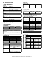
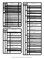
CONTENTS
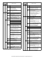
[1] NOTE FOR SERVICING . . . . . . . . . . . . . . . . . . . . . . . . . . . . . . . . 1-1
[2] CONFIGURATION . . . . . . . . . . . . . . . . . . . . . . . . . . . . . . . . . . . . . 2-1
[3] SPECIFICATIONS . . . . . . . . . . . . . . . . . . . . . . . . . . . . . . . . . . . . . 3-1
[4] CONSUMABLE PARTS . . . . . . . . . . . . . . . . . . . . . . . . . . . . . . . . . 4-1
[5] UNPACKING AND INSTALLATION . . . . . . . . . . . . . . . . . . . . . . . . 5-1
[6] EXTERNAL VIEW AND INTERNAL STRUCTURE . . . . . . . . . . . . 6-1
[7] ADJUSTMENTS, SETTING . . . . . . . . . . . . . . . . . . . . . . . . . . . . . . 7-1
[8] SIMULATION . . . . . . . . . . . . . . . . . . . . . . . . . . . . . . . . . . . . . . . . . 8-1
[9] TROUBLE CODE LIST . . . . . . . . . . . . . . . . . . . . . . . . . . . . . . . . . 9-1
[10] DISASSEMBLY, ASSEMBLY AND MAINTENANCE . . . . . . . . . . 10-1
[11] OTHERS . . . . . . . . . . . . . . . . . . . . . . . . . . . . . . . . . . . . . . . . . . . 11-1
[12] ELECTRICAL SECTION . . . . . . . . . . . . . . . . . . . . . . . . . . . . . . . 12-1
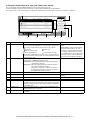
Parts marked with “ ” are important for maintaining the safety of the set. Be sure to replace these parts with
specified ones for maintaining the safety and performance of the set.
This document has been published to be used
for after sales service only.
The contents are subject to change without notice.
CONTENTS
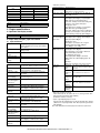
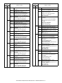
[1]
NOTE FOR SERVICING
1. Warning for servicing . . . . . . . . . . . . . . . . . . . . . . . . . . . . . 1-1
2. Precautions for servicing . . . . . . . . . . . . . . . . . . . . . . . . . . 1-1
3. Note for installing site . . . . . . . . . . . . . . . . . . . . . . . . . . . . 1-1
[2]
CONFIGURATION
1. Line of machines and options . . . . . . . . . . . . . . . . . . . . . . 2-1
2. Combination of options list. . . . . . . . . . . . . . . . . . . . . . . . . 2-2
[3]
SPECIFICATIONS
1. Basic specifications . . . . . . . . . . . . . . . . . . . . . . . . . . . . . .
2. Operation specifications . . . . . . . . . . . . . . . . . . . . . . . . . .
A. Common operation . . . . . . . . . . . . . . . . . . . . . . . . . . . .
B. Copy mode . . . . . . . . . . . . . . . . . . . . . . . . . . . . . . . . . .
3. Engine specifications . . . . . . . . . . . . . . . . . . . . . . . . . . . . .
A. Operation and display section . . . . . . . . . . . . . . . . . . . .
B. Paper feed, transport, paper exit section . . . . . . . . . . .
C. Optical (Image scanning) section . . . . . . . . . . . . . . . . .
D. Scanner (exposure) section . . . . . . . . . . . . . . . . . . . . .
E. Image process section . . . . . . . . . . . . . . . . . . . . . . . . .
F. Fusing . . . . . . . . . . . . . . . . . . . . . . . . . . . . . . . . . . . . . .
G. Drive . . . . . . . . . . . . . . . . . . . . . . . . . . . . . . . . . . . . . . .
4. Additional functions, copy functions,
and expanded functions. . . . . . . . . . . . . . . . . . . . . . . . . . .
5. Safety and environmental protection standards . . . . . . . .
6. Environment conditions . . . . . . . . . . . . . . . . . . . . . . . . . . .
7. IMC board functions. . . . . . . . . . . . . . . . . . . . . . . . . . . . . .
8. Printer function
(AR-M256/ M257/ M316/ M317/ 5625/ 5631) . . . . . . . . . .
A. “Sharp Printer Language with Compression (SPLC)”
Printer function . . . . . . . . . . . . . . . . . . . . . . . . . . . . . . .
B. Printer driver specification . . . . . . . . . . . . . . . . . . . . . . .
C. Interface . . . . . . . . . . . . . . . . . . . . . . . . . . . . . . . . . . . .
D. System outline. . . . . . . . . . . . . . . . . . . . . . . . . . . . . . . .
9. Printer function (AR-M258/ M318) . . . . . . . . . . . . . . . . . . .
A. Basic function . . . . . . . . . . . . . . . . . . . . . . . . . . . . . . . .
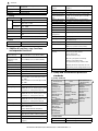
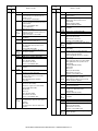
[4]
CONSUMABLE PARTS
1. Supply system table. . . . . . . . . . . . . . . . . . . . . . . . . . . . . .
A. SEC/ SECL/ LAG . . . . . . . . . . . . . . . . . . . . . . . . . . . . .
B. Europe/ East Europe/ Russia/
Australia/ New Zealand . . . . . . . . . . . . . . . . . . . . . . . . .
C. Asia affiliates . . . . . . . . . . . . . . . . . . . . . . . . . . . . . . . . .
D. SMEF/ Israel/ Philippines/ Agent. . . . . . . . . . . . . . . . . .
E. Taiwan. . . . . . . . . . . . . . . . . . . . . . . . . . . . . . . . . . . . . .
F. Hong Kong . . . . . . . . . . . . . . . . . . . . . . . . . . . . . . . . . .
G. China. . . . . . . . . . . . . . . . . . . . . . . . . . . . . . . . . . . . . . .
2. Maintenance parts list . . . . . . . . . . . . . . . . . . . . . . . . . . . .
A. SDSCA/ SECL/ LAG (AR-M257/ M317) . . . . . . . . . . . .
B. SEEG/ SUK/ SCA/ SCNZ/ SEA/ SEES/ SEZ/ SEIS/
SEB/ SEN/ SEF/ SMEF/ Russia/ Special country
(AR-M256/ M316, AR-5625/ 5631) . . . . . . . . . . . . . . . .
C. STCL/ SRH/ SRS/ SRSSC/ SBI/ Agent (All model) . . .
2. Production number identification . . . . . . . . . . . . . . . . . . . .
<TD cartridge>. . . . . . . . . . . . . . . . . . . . . . . . . . . . . . . . . .
<Drum> . . . . . . . . . . . . . . . . . . . . . . . . . . . . . . . . . . . . . . .
3. Environment conditions . . . . . . . . . . . . . . . . . . . . . . . . . . .
A. Ambient conditions for transporting. . . . . . . . . . . . . . . .
B. Ambient storage conditions (sealed) . . . . . . . . . . . . . . .
C. Operating ambient conditions . . . . . . . . . . . . . . . . . . . .
4. Life (packed conditions). . . . . . . . . . . . . . . . . . . . . . . . . . .
3-1
3-1
3-1
3-1
3-2
3-2
3-2
3-3
3-3
3-3
3-4
3-4
[5]
[6]
3-4
3-4
3-5
3-5
3-6
3-6
3-6
3-8
3-8
3-8
3-8
4-1
4-1
[7]
5-1
5-1
5-1
5-1
5-2
5-2
5-2
5-3
5-3
5-4
5-4
5-4
5-4
5-5
5-5
5-6
5-7
5-7
5-8
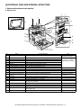
EXTERNAL VIEW AND INTERNAL STRUCTURE
1. Name and function of each section . . . . . . . . . . . . . . . . . .
A. External view . . . . . . . . . . . . . . . . . . . . . . . . . . . . . . . . .
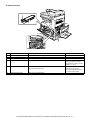
B. Internal structure . . . . . . . . . . . . . . . . . . . . . . . . . . . . . .
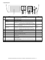
C. Operation panel . . . . . . . . . . . . . . . . . . . . . . . . . . . . . . .
D. Job status screen
(common to copy, print, network scan and fax) . . . . . . .
E. Motor, Solenoid, Clutch . . . . . . . . . . . . . . . . . . . . . . . . .
F. Sensor . . . . . . . . . . . . . . . . . . . . . . . . . . . . . . . . . . . . . .
G. PWB unit . . . . . . . . . . . . . . . . . . . . . . . . . . . . . . . . . . . .
H. Section . . . . . . . . . . . . . . . . . . . . . . . . . . . . . . . . . . . . . .
6-4
6-5
6-5
6-6
6-6
ADJUSTMENTS, SETTING
1. List of adjustment items . . . . . . . . . . . . . . . . . . . . . . . . . . .
2. Copier adjustment. . . . . . . . . . . . . . . . . . . . . . . . . . . . . . . .
A. Process section . . . . . . . . . . . . . . . . . . . . . . . . . . . . . . .
B. Mechanism section. . . . . . . . . . . . . . . . . . . . . . . . . . . . .
C. Image density (exposure) adjustment . . . . . . . . . . . . . .
7-1
7-1
7-1
7-3
7-9
6-1
6-1
6-2
6-3
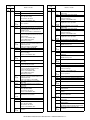
[8]
SIMULATION
(Diagnostics, setup, adjustment value input, data display)
1. Outline and purpose . . . . . . . . . . . . . . . . . . . . . . . . . . . . . . 8-1
2. Code-type simulation . . . . . . . . . . . . . . . . . . . . . . . . . . . . . 8-1
A. Operating procedures and operations . . . . . . . . . . . . . . 8-1
B. How to change the simulation adjustment value set
by the touch panel in the adjustment value entry
process. . . . . . . . . . . . . . . . . . . . . . . . . . . . . . . . . . . . . . 8-1
3. Simulation code list . . . . . . . . . . . . . . . . . . . . . . . . . . . . . . . 8-3
4. Details . . . . . . . . . . . . . . . . . . . . . . . . . . . . . . . . . . . . . . . . . 8-6
[9]
TROUBLE CODE LIST
1. List . . . . . . . . . . . . . . . . . . . . . . . . . . . . . . . . . . . . . . . . . . . 9-1
2. Self diagnostics . . . . . . . . . . . . . . . . . . . . . . . . . . . . . . . . . 9-2
4-1
4-1
4-1
4-1
4-1
4-1
4-2
4-2
4-2
4-3
4-4
4-4
4-4
4-4
4-4
4-4
4-4
4-4
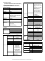
UNPACKING AND INSTALLATION
1. Installation. . . . . . . . . . . . . . . . . . . . . . . . . . . . . . . . . . . . . .
A. Environment . . . . . . . . . . . . . . . . . . . . . . . . . . . . . . . . . .
B. Power source . . . . . . . . . . . . . . . . . . . . . . . . . . . . . . . . .
C. Transport . . . . . . . . . . . . . . . . . . . . . . . . . . . . . . . . . . . .
D. Other precautions. . . . . . . . . . . . . . . . . . . . . . . . . . . . . .
2. Removal of protective material and fixing screw . . . . . . . .
3. Removal and storage of fixing pin . . . . . . . . . . . . . . . . . . .
4. Developer cartridge installation . . . . . . . . . . . . . . . . . . . . .
5. Toner cartridge installation . . . . . . . . . . . . . . . . . . . . . . . . .
6. Toner density sensor level adjustment . . . . . . . . . . . . . . . .
7. Tray paper size setting . . . . . . . . . . . . . . . . . . . . . . . . . . . .
A. Trays 1 – 4 . . . . . . . . . . . . . . . . . . . . . . . . . . . . . . . . . . .
B. Manual feed tray. . . . . . . . . . . . . . . . . . . . . . . . . . . . . . .
8. Installation of options . . . . . . . . . . . . . . . . . . . . . . . . . . . . .
A. AR-P27. . . . . . . . . . . . . . . . . . . . . . . . . . . . . . . . . . . . . .
B. AR-PK1N . . . . . . . . . . . . . . . . . . . . . . . . . . . . . . . . . . . .
C. AR-PF1/PF2 . . . . . . . . . . . . . . . . . . . . . . . . . . . . . . . . . .
D. MX-NSX1 . . . . . . . . . . . . . . . . . . . . . . . . . . . . . . . . . . . .
F. AR-SM5/SM6 . . . . . . . . . . . . . . . . . . . . . . . . . . . . . . . . .
[10] DISASSEMBLY, ASSEMBLY AND MAINTENANCE
1. Maintenance table . . . . . . . . . . . . . . . . . . . . . . . . . . . . . . 10-1
(For 25cpm) . . . . . . . . . . . . . . . . . . . . . . . . . . . . . . . . . . . 10-1
(For 31cpm) . . . . . . . . . . . . . . . . . . . . . . . . . . . . . . . . . . . 10-2
2. Counter clear . . . . . . . . . . . . . . . . . . . . . . . . . . . . . . . . . . 10-3
3. List of disassembly and assembly . . . . . . . . . . . . . . . . . . 10-3
4. Details of disassembly and assembly . . . . . . . . . . . . . . . 10-3
A. Process unit . . . . . . . . . . . . . . . . . . . . . . . . . . . . . . . . 10-3
B. Developing section . . . . . . . . . . . . . . . . . . . . . . . . . . . 10-5
C. Fusing section . . . . . . . . . . . . . . . . . . . . . . . . . . . . . . . 10-6
D. Optical section. . . . . . . . . . . . . . . . . . . . . . . . . . . . . . . 10-8
E. Paper feed section . . . . . . . . . . . . . . . . . . . . . . . . . . . 10-9
F. Side door unit . . . . . . . . . . . . . . . . . . . . . . . . . . . . . . 10-15
G. 1st paper exit unit . . . . . . . . . . . . . . . . . . . . . . . . . . . 10-16
H. 2nd paper exit unit. . . . . . . . . . . . . . . . . . . . . . . . . . . 10-17
I. Laser unit . . . . . . . . . . . . . . . . . . . . . . . . . . . . . . . . . 10-18
J. Power unit . . . . . . . . . . . . . . . . . . . . . . . . . . . . . . . . . 10-18
K. PWB . . . . . . . . . . . . . . . . . . . . . . . . . . . . . . . . . . . . . 10-19
L. Ozone filter . . . . . . . . . . . . . . . . . . . . . . . . . . . . . . . . 10-21
M. Drive section . . . . . . . . . . . . . . . . . . . . . . . . . . . . . . . 10-21
N. Transport section . . . . . . . . . . . . . . . . . . . . . . . . . . . 10-23
O. Operation section . . . . . . . . . . . . . . . . . . . . . . . . . . . 10-24
P. Switch . . . . . . . . . . . . . . . . . . . . . . . . . . . . . . . . . . . . 10-24
[11] OTHERS
1. Flash ROM version-up procedure . . . . . . . . . . . . . . . . . .
A. Program download method
(for Copier, and fax program) . . . . . . . . . . . . . . . . . . .
B. Printer Control Board firmware download method . . .
C. Others (Troubleshooting) . . . . . . . . . . . . . . . . . . . . . .
2. Key operator program list . . . . . . . . . . . . . . . . . . . . . . . .
A. Common program of digital copier . . . . . . . . . . . . . . .
B. Copy function setting program . . . . . . . . . . . . . . . . . .
C. Printer function setting program . . . . . . . . . . . . . . . . .
D. Network scanner function setting program . . . . . . . . .
3. E-mail Status/ E-mail Alerts . . . . . . . . . . . . . . . . . . . . . . .
A. Basic functions . . . . . . . . . . . . . . . . . . . . . . . . . . . . . .
B. Main body specifications . . . . . . . . . . . . . . . . . . . . . . .
C. Printer controller specifications . . . . . . . . . . . . . . . . . .
D. Handling of transmission data . . . . . . . . . . . . . . . . . . .
11-1
11-1
11-2
11-3
11-3
11-3
11-4
11-4
11-5
11-6
11-6
11-6
11-6
11-6
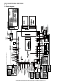
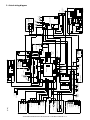
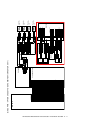
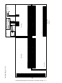
[12] ELECTRICAL SECTION
1. Block diagram . . . . . . . . . . . . . . . . . . . . . . . . . . . . . . . . . 12-1
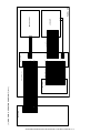
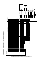
2. Actual wiring diagram . . . . . . . . . . . . . . . . . . . . . . . . . . . 12-2
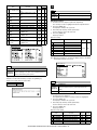
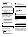
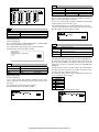
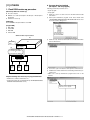
[1] NOTE FOR SERVICING
This Service Manual uses some photographs to assure safe operation.
Please understand the meanings of photographs before servicing.
8) The machine has got sharp edges inside. Be careful not to damage fingers when servicing.
WARNING: If this WARNING should be ignored, a serious danger
to life or a serious injury may result.
CAUTION: If this CAUTION should be ignored, injury or damage
to property could result.
9) Do not throw toner or a toner cartridge in a fire. Otherwise, toner
may pop and burn you.
1. Warning for servicing
1) Be sure to connect the power cord only to a power outlet that
meets the specified voltage and current requirements.
10) When replacing the lithium battery on the PWB, use only the specified battery. If a battery of different specification is used, it may not
be compatible and cause breakdown or malfunction of the
machine.
11) When carrying an electric unit or a PWB, use an anti-static (electricity) bag. Failure to do so may cause component failure or
machine malfunction.
Avoid complex wiring, which may lead to a fire or an electric shock.
2) If there is any abnormality such as smoke or an abnormal smell,
interrupt the job and disconnect the power plug.
It may cause a fire or an electric shock.
3) Be sure the machine is properly grounded. Failure to ground the
machine properly may result in an electric shock or fire.
To protect the machine and the power unit from lightening, grounding must be made.
4) When connecting the ground wire, never connect it to the following
points as it may cause an explosion, fire, or an electric shock:
• Gas tube
3. Note for installing site
Do not install the machine at the following sites.
1) Place of high temperature, high humidity, low temperature, low
humidity, place under an extreme change in temperature and
humidity.
Paper may get damp and form dews inside the machine, causing
paper jam or copy dirt.
For operating and storing conditions, refer to the specifications
described later.
2) Place of much vibrations
• Lightning conductor
• A water pipe or a water faucet, which is not recognized as a
grounding object by the authorities.
• Grounding wire for telephone line
5) Do not damage, break, or stress the power cord. Do not put heavy
objects on the power cord. Do not bend or pull the cord forcefully. It
may cause a fire or electric shock.
6) Keep the power cable away from a heat source.
Do not insert the power plug with dust on it into a power outlet.
It may cause a fire or an electric shock.
7) Do not put a receptacle with water in it or a metal piece which may
drop inside the machine.
It may cause a fire or an electric shock.
8) Do not touch the power plug, insert a telephone jack, perform service or operate the machine with wet or oil hands. It may cause an
electric shock.
2. Precautions for servicing
1) When servicing, disconnect the power plug, the printer cable, the
network cable, and the telephone line from the machine, except
when performing the communication test, etc.
It may cause an injury or an electric shock.
2) There is a high temperature area inside the machine. Use extreme
care when servicing.
3) There is a high voltage section inside the machine which may
cause an electric shock . Be careful when servicing.
4) Do not disassemble the laser unit. Do not insert a reflective material such as a screwdriver in the laser beam path.
It may damage eyes by reflection of laser beams.
5) When servicing the machine while operating, be careful not to
make contact with chains, belts, gear, and any other moving parts.
It may cause a breakdown.
3) Poorly ventilated place
An electro-static type copier will produce ozone inside it.
The quantity of ozone produced is designed to a low level so as
not to affect human bodies. However, continuous use of such a
machine may produce a smell of ozone. Install the machine in a
well ventilated place, and ventilate occasionally.
4) Place of direct sunlight.
Plastic parts and ink may be deformed, discolored, or may undergo
qualitative change.
It may cause a breakdown or copy dirt.
5) Place which is full of organic gases such as ammonium
The organic photoconductor (OPC) drum used in the machine may
undergo qualitative change due to organic gases such as ammonium.
Installation of this machine near a diazo-type copier may result in
dirt copy.
6) Place of much dust
When dusts enter the machine, it may cause a breakdown or copy
dirt.
7) Place near a wall
Some machine require intake and exhaust of air.
If intake and exhaust of air are not properly performed, copy dirt or
a breakdown may be resulted.
8) Unstable or slant surface
If the machine drops or fall down, it may cause an injury or a breakdown.
If there are optional paper desk and the copier desk specified, it is
recommendable to use them.
When using the optional desk, be sure to fix the adjuster and lock
the casters.
6) Do not leave the machine with the cabinet disassembled.
Do not allow any person other than a serviceman to touch inside
the machine. It may cause an electric shock, a burn, or an injury.
7) When servicing, do not breathe toner, developer, and ink excessively. Do not get them in the eyes.
If toner, developer, or ink enters you eyes, wash it away with water
immediately, and consult a doctor if necessary.
AR-M256/M257/M258/M316/M317/M318/5625/5631 NOTE FOR SERVICING 1 - 1
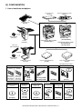
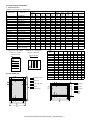
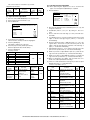
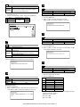
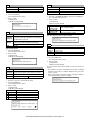
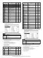
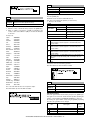
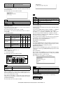
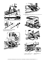
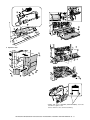
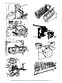
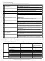
[2] CONFIGURATION
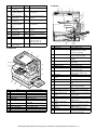
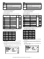
1. Line of machines and options
Document cover
[AR-VR6]
Job separator tray
[AR-TR3]
Reversing single pass feeder
[AR-RP7]
[RSPF]
Copier/Printer (PCL)
Network model
[AR-M258/M318]
Staple cartridge
[AR-SC1]
Copier/Printer (SPLC) model
[AR-M257/M317]
Finisher
[AR-FN5A]
Punch unit
[AR-PN1A/B/C/D]
Copier/Printer (SPLC) model
[AR-M256/M316]
[AR-5625/5631]
Staple cartridge
[AR-SC2]
Paper feed unit (500 Seets)
[AR-D30]
Saddle stitch finisher
[AR-F14N]
Paper feed unit (500c2 Seets)
[AR-D31]
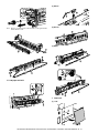
[AR-M256/M316/M257/M317]
Data security kit
[Commercial
version]
FAX expantion kit
Expantion memory board
FAX memory (8MB)
Printer expantion kit (PCL)
[AR-FX7]
[AR-SM5](256MB)
[AR-SM6](512MB)
[AR-MM9]
[AR-P27]
[Authentication
version]
[AR-FR24U]
[AR-FR24]
(For 25cpm)
(For 25cpm)
[AR-FR25U]
[AR-FR25]
(For 31cpm)
(For 31cpm)
[AR-M256/M316/M257/M317/M258/M318]
Application integration
module kit
Sharpdesk
license kit
Network scanner
expantion kit
Barcode font kit
Flash ROM kit
PS3 expantion kit
[MX-AMX1]
[MX-USX1/
MX-USX5/
MX-US10/
MX-US50/
MX-USA0]
[MX-NSX1]
[AR-PF1]
[AR-PF2]
[AR-PK1N]
AR-M256/M257/M258/M316/M317/M318/5625/5631 CONFIGURATION 2 - 1
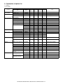
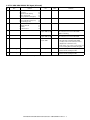
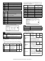
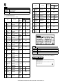
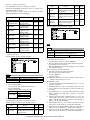
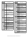
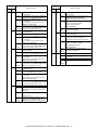
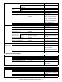
2. Combination of options list
F : Installable
✕: Not available
Option
Section
Item
Main unit Model
Model
Note
AR-M256/ AR-M257/ AR-M258/ AR-5625/
M316
M317
M318
5631
Automatic document Document feeder
feeder and OC
Document cover
AR-RP7
F
Standard
F
F
AR-VR6
F
✕
F
F
Paper feed system
Paper feed unit (500 sheets)
AR-D30
F
F
F
F
500 x 1 (80g/m2)
Paper feed unit
(500 x 2 sheets)
AR-D31
F
F
F
F
500 x 2 (80g/m2)
Paper exit system
AR-TR3
F
F
F
F
Finisher
Job separator tray
AR-FN5A
F
F
F
F
Staple cartridge
AR-SC1
F
F
F
F
Saddle stitch finisher
AR-F14N
F
F
F
F
Staple cartridge
Punch unit
FAX system
Printer system
Memory board
Software
Data security
AR-SC2
F
F
F
F
AR-PN1A
F
F
F
F
AR-PN1B
F
F
F
F
AR-PN1C
F
F
F
F
AR-PN1D
F
F
F
F
FAX expansion kit
AR-FX7
F
F
F
F
FAX memory (8MB)
AR-MM9
F
F
F
F
Printer expansion kit (PCL)
AR-P27
F
F
Standard
✕
Bar code font kit
AR-PF1
F
F
F
✕
Flash ROM kit
AR-PF2
F
F
F
✕
PS3 expansion kit
AR-PK1N
F
F
F
✕
256MB expansion memory
board
AR-SM5
F
F
F
F
512MB expansion memory
board
AR-SM6
F
F
F
F
Network scanner expansion
kit
MX-NSX1
F
F
F
✕
Sharpdesk 1 license kit
MX-USX1
F
F
F
✕
Sharpdesk 5 license kit
MX-USX5
F
F
F
✕
Sharpdesk 10 license kit
MX-US10
F
F
F
✕
Sharpdesk 50 license kit
MX-US50
F
F
F
✕
For AR-FN5A
For AR-F14N
AR-P27 must be installed.
AR-P27 must be installed.
Sharpdesk 100 license kit
MX-USA0
F
F
F
✕
Application integration
module kit
MX-AMX1
F
F
F
✕
AR-P27 must be installed.
Data security kit
(Commercial version)
AR-FR24U
F
F
F
F
For 25cpm
AR-FR25U
F
F
F
F
For 31cpm
AR-FR24
F
F
F
F
For 25cpm
AR-FR25
F
F
F
F
For 31cpm
Data security kit
(Authentication version)
AR-M256/M257/M258/M316/M317/M318/5625/5631 CONFIGURATION 2 - 2
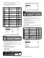
[3] SPECIFICATIONS
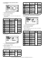
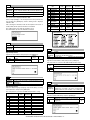
(4) Job speed
a. First Copy Time
1. Basic specifications
(1) Type
Machine Type
Desktop type
(2) External dimensions
Floor to OC top
surface
Floor to Glass
surface
Floor to RSPF
surface
Frequency
Power switch
When paper of A4/ 8.5 x 11 is fed from the main unit tray, the polygon motor is rotating.
b. Copy speed
Engine
AR-M256/ M257/
M258/ 5625
25 cpm (100%)
AR-M316/ M317/
M318/ 5631
27 cpm (87%)
(First copy is not included.)
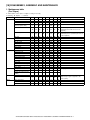
c. Multi copy speed (sheets/ minute)
55 kg
Document Size
100V: 110V/ 120V to 127V
200V: 220V to 240V
50/ 60Hz common
One power source
25 sheet model
23 sec. or less
Yes
31 sheet model
25 sec. or less
(2) Jam recovery time
About 10sec.
However, the conditions for warming up of fusing and toner control
are excluded.
(Condition: Leaving the machine for 60 sec after opening the door,
standard condition, polygon stop.)
A3
B4
A4
A4R
B5
B5R
A5
11" × 17"
8-1/ 2" × 14"
8-1/ 2" × 13"
8-1/ 2" × 11"
8-1/ 2" × 11"R
5.5 × 8.5
AR-M256/ M257/
M258/ 5625
13
15
25
18
25
20
25
13
14
15
25
18
25
AR-M316/ M317/
M318/ 5631
17
20
31
24
31
24
31
17
20
20
31
24
31
∗ Same speed for Normal/ Enlargement/ Reduction.
(5) Max. multi-copy (print) quantity
999 sheets
(6) Picture quality
A. Resolution
B. Copy mode
(1) Document size
A3 paper (11" × 17")
(2) Picture quality mode
Density adjustment step
1 step
5 steps
5 steps
5 steps
Toner save mode
Selectable
Selectable
Selectable
—
(3) Copy magnification ratio
Copy magnification ratio
Magnification range/ fixed magnification
Zoom width
25 to 400% (50 to 200% for RSPF)
Fixed magnification
AB Series : 25, 50, 70, 81, 86, 100, 115,
mode
122, 141, 200, 400%
Inch Series: 25, 50, 64, 77, 100, 121, 129,
200, 400%
Independent
25 to 400% for horizontal/ vertical
magnification width
(50 to 200% for RSPF)
Magnification
precision
Less than 9.3 sec.
Monochrome scan resolution: 600 x 600dpi (Default)
(1) Warm up time
Picture quality mode
Text Auto mode
Text mode
Text/ Photo mode
Photo mode
Less than 4.8 sec.
Less than 9.3 sec.
49.2 kg (with OC)
A. Common operation
Max. document size
Less than 4.8 sec.
RSPF
S to S
2. Operation specifications
Warm-up time
Pre-heat function
Platen
∗ S to S: A4/ 8.5 x 11 documents 11 sheets, copy 1 sets
(4) Power supply
Voltage
AR-M316/ M317/
M318/ 5631
∗ Measurement conditions:
623 (W) x 615 (D) x 640.5 (H)mm
(24.5 (W) x 24.2 (D) x 25.2 (H) inch)
623 (W) x 615 (D) x 665 (H)mm
(24.5 (W) x 24.2 (D) x 26.2 (H) inch)
623 (W) x 615 (D) x 786 (H)mm
(24.5 (W) x 24.2 (D) x 30.9 (H) inch)
(3) Weight
AR-M256/ M258/
M316/ M318/ 5625/
5631
AR-M257/ M317
AR-M256/ M257/
M258/ 5625
Platen/ DSPF
Scan
resol
ution
(dpi)
Input
and
send
resol
ution
(dpi)
Copy mode
Platen
RSPF
400 × 600dpi
400 × 600dpi
Fax send mode
Select mode
Transmission
resolution
Half tone
Scanner mode
Select mode
Input resolution:
OC
Input resolution:
RSPF
Transmission
resolution
Normal
text
203.2 ×
97.8
×
Fine
text
203.2 ×
195.6
F
Super
fine test
203.2 ×
391
F
Ultra
fine text
406.4 ×
391
F
200 ×
200
600 ×
600
600 ×
367
200 ×
200
300 ×
300
600 ×
600
600 ×
367
300 ×
300
400 ×
400
600 ×
600
600 ×
367
400 ×
400
600 ×
600
600 ×
600
600 ×
367
600 ×
600
Normal copy: 100%±1.0%
Enlargement copy: Set magnification ±1.0%
Reduction copy: Set magnification ±1.0%
AR-M256/M257/M258/M316/M317/M318/5625/5631 SPECIFICATIONS 3 - 1
• Manual feed section
Position
Copy magnification
ratio
25% to 49%
50% to 69%
70% to 94%
95% to 105%
106% to 141%
142% to 400%
Center
—
3.2 line/mm
3.6 line/mm
5.0 line/mm
5.0 line/mm
5.0 line/mm
Corners
—
2.8 line/mm
3.2 line/mm
4.5 line/mm
4.5 line/mm
4.5 line/mm
Transport reference
Paper size display
Paper size setting
Paper type
b. Gradation
Read
Write
256 gradations
2 gradations
3. Engine specifications
A. Operation and display section
Display unit
Operation system
Dot matrix LCD, Touch panel
Button switch system
B. Paper feed, transport, paper exit section
(1)
Allowable paper
type and weight for
paper feed
Paper feed ability
Type
Paper feed method
Dehumidification
heater
Paper size label
Maximum weight
setting
2-stage paper feed tray + multi manual feed
(Can be extended up to 4 stages by installation
of the options.)
Paper is fed from the above by the front
loading system.
No
Paper capacity
(Multi paper feed)
Yes
No
• Tray 1
Paper size
Paper size change
method
Paper type setting
Paper size setting
when shipping
Allowable paper
type and weight for
paper feed
Paper capacity
Paper type
Paper remaining
detection
A3/ B4/ A4/ A4R/ B5/ B5R/ A5/ 16K/ 16KR/
11 × 17/ 8.5 × 14/ 8.5 × 13/ 8.5 × 11/ 8.5 × 5.5
Changeable by the user.
(By the operation on the LCD panel)
Normal paper, Recycled paper, Letterhead,
Color paper
AB series: A4
Inch series: 8.5 x 11
56 to 105g/m2/ 15 to 28lbs Bond
500 sheets (80g/m2 paper) (Plain paper)
Plain paper (56 to 80g/m2), Normal paper
(80 to 105g/m2), Letterhead, Color paper
No (Only paper empty detection)
Paper size change
method
Paper type setting
Paper size setting
when shipping
Allowable paper
type and weight for
paper feed
Paper capacity
Paper type
Paper remaining
detection
Single paper feed:
Plain paper (52 to 128g/m2), recycled paper,
OHP, label sheet, gift wrapping paper,
postcards, double postal card (no folding line),
envelope, postcard paper, coarse paper, No. 2
master drawing, Thick paper (Max. 200g/m2)
Multi paper feed:
Plain paper (52 to 128g/m2), special paper,
thick paper (Max. 200g/m2)
Single paper feed:
Plain paper, special paper, No. 2 master
drawing, thick paper (Max. 200g/m2)
52 to 200g/m2 (14 to 54lbs)
Normal paper: 100 sheets
(Plain paper: 52 to 80g/m2)
Recycled paper/ coarse paper: 100 sheets
Postcards/ Double postal card
(no folding line): 30 sheets
Thick paper (Max. 200g/m2): 30 sheets
OHP/ Label sheet/ Gift wrapping paper: 40
sheets
Envelope
(AB series: 10 sheets, Inch series 5 sheets)
Automatic A3 / A4 / 11 x 17 / 8.5 × 14/
detection- 8.5 x 13 */ 8.5 x 11 / 8.5 x 11R /
AB
5.5 x 8.5
Automatic A3 / B4 / A4 / A4R / A5 / 11 x 17 /
detection- 8.5 × 14/ 8.5 x 13 */ 8.5 x 11
inch
Automatic A3 / B4 / A4 / A4R / B5 / B5R /
detection- A5 / 8K / 16K
China
Automatic A3 / B4 / A4 / A4R / B5 / B5R /
detection- A5 / 11 × 17/ 8.5 x 14 / 8.5 x 11
Taiwan
Detection Yes
disregard
setting
∗ Overseas envelopes for check:
• Tray 2
Paper size
Paper size
detection
Center reference
AB series: A3 to A6R, Postcard
Inch series: 11 x 17 to 5.5 x 8.5
A3/ A4, 11 x 17, B4/ B5, 8.5 x 14, A4R/ A5,
B5R, A5R, 5.5 x 8.5
Multi paper feed:
Plain paper (52 to 80g/m2), recycled paper,
OHP, label sheet, gift wrapping paper,
postcards, double postal card (no folding line),
envelope, coarse paper, thick paper
A3/ B4/ A4/ A4R/ B5R/ 16KR/ 8K/11 × 17/
8.5 × 14/ 8.5 × 13/ 8.5 × 11/ 8.5 × 11R
Changeable by the user.
(By the operation on the LCD panel)
Normal paper, Recycled paper, Letterhead,
Color paper
AB series: A4
Inch series: 8.5 x 11
56 to 105g/m2/ 15 to 28lbs Bond
#10 Commercial, DL, C5 ("Must be free of passing trouble" with :
Must pass through machine with reliability.)
(Evaluation reference envelope)
∗ Types of gift wrapping paper for check:
Aioi Envelope gift wrapping paper A3, B4, A4, B5, Mino Size, Hanshi
(“Must be free of passing trouble” with : Must pass through machine
with reliability.)
Note: FAX data print from manual paper feed cannot be performed.
500 sheets (80g/m2 paper) (Plain paper)
Plain paper (56 to 80g/m2), Normal paper
(80 to 105g/m2), Letterhead, Color paper
No (Only paper empty detection)
AR-M256/M257/M258/M316/M317/M318/5625/5631 SPECIFICATIONS 3 - 2
C. Optical (Image scanning) section
• Duplex
Type
Paper size
Type and weight of
paper which can be
passed
Switchback system
A3, B4, A4, A4R, B5, B5R, 11 x 17, 8.5 x 14,
8.5 x 13, 8.5 x 11, 8.5 x 11R
56 to 105g/m2/ 15 to 21.3lbs Bond
Duplex print from manual paper feed can be
performed.
(Except for heavy paper, OHP sheet, and
special paper.)
∗ Judgment is made by setting the paper type
on the operation panel.
(2) Finishing ability
Paper exit section
Paper exit face
Capacity
Full detection
Paper detection
Finishing
Offset function
Stapling
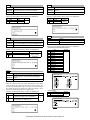
(1) Type
Document table
Document table fixed type (Flat-bed type)
(2) Document reference position
Document table
Rear left reference
(3) Resolution
Main scanning direction
400 dpi
Sub scanning direction
600 dpi
(4) Gradation
256 gradations (8-bit)
Paper exit tray (1 tray)
Face down
500 sheets (80g/m2 paper)
No
Yes
Yes
Depending on the shifter.
Available when the finisher is installed.
(3) Job separator exit tray (AR-TR3)
Condition
In case of Optional function (printer, FAX) is
set up as MFD.
Simultaneous
wrapping in kit
Job separator tray
Setting manual book
Simultaneous
wrapping
Setting manual book
Function
This exit tray is set up above main exit tray, and
can separate copier exit, printer exit and FAX
exit.
Many of tray
1 (this tray can not set up more than 2)
Separator system
By control of main machine
Exit paper size
All sizes of paper except for postcards (A6)
and envelopes.
(5) Original size/ Scanning area
a. Max. original size
A3 paper (11" × 17")
(6) Scanning speed
122mm/sec (600 dpi: magnification ratio 100%)
(AR-M256/ M257/ M258/ 5625)
145mm/sec (600 dpi: magnification ratio 100%)
(AR-M316/ M317/ M318/ 5631)
(7) Light source (lamp)
Type
None-electrode xenon lamp
Drive voltage
1.5 kV
(8) Read sensor
Type
2
Exit paper weight
52 to 128g/m (14 to 34.1lbs)
Paper pass
Center (same as main unit)
Exit area/ finishing
Face-down paper exit to the upper surface of
the main unit paper exit section
Machine weight
0.6 kg
Reduction optical system image sensor (CCD)
Monochrome
D. Scanner (exposure) section
(1) Resolution
Main scanning direction
Sub scanning direction
600 dpi
600 dpi
(2) Gradation
2 gradations
(3) Laser unit specifications
r.p.m.
28,819 rpm (26 sheet model/FAX output)
34,252 rpm (31 sheet model)
2
Exit capacity
100 sheets (80g/m paper)
Tray full detector
Yes
Mirror surfaces
6 faces
Laser power
0.16mW (26 sheet model/FAX output)
0.18mW (31 sheet model)
Concept of function
Upper exit tray
(Job separator)
Copy/ FAX/ Printer
(This setting can be done by users.)
Lower exit tray
(main machine
exit tray)
Copy/ Printer/ FAX
(This setting can be done by users.)
Laser beam size
60µ (Main scan) x 70µ (Sub scan)
Laser wave length
785nm
E. Image process section
Imaging speed
Photo
conductor
Type
LIFE
Toner
Type
LIFE
Charge
System
Voltage
System
Voltage
Transfer
Exposure
600 dpi: 122 mm/sec.
(AR-M256/ M257/ M258/ 5625)
600 dpi: 145 mm/sec.
(AR-M316/ M317/ M318/ 5631)
OPC drum (dia. 30mm)
25 sheet model: 75,000 sheets
31 sheet model: 100,000 sheets
Developer (Black)
25,000 sheets
(Toner, life:
25k,
Developer life: 75k (26 sheet model)
100k (31 sheet model))
Charged saw-tooth
560µA constant electric current
Transfer roller
18µA (electric current)
None-electrode xenon lamp
AR-M256/M257/M258/M316/M317/M318/5625/5631 SPECIFICATIONS 3 - 3
: '07/Oct/15
1
Developing
Separation
Discharge
Cleaning
Dry, 2-component magnetic brush
development
(–) DC scorotron
—
Contacted blade
Yes (Conditions are set with the key operator
program.)
Message display
Yes
Key operator program
Yes
Yes (A PCL printer board is required (TCP/
IP only). To use another protocol, an NIC
card is required.)
Heat roller
Printer status monitor/
Printer administration
utility
Type
Halogen lamp
Wireless LAN support
Yes (A 3rd party part is recommended.)
Voltage
100V: 110V/ 120V to 127V
200V: 220V to 240V
Coin vendor support
Yes (Option only for the models for dealers)
Auditor support
Yes
Power
consumption
Main : 650W
Sub : 550W
Duplex
Yes (Standard)
F. Fusing
Type
Lamp
Auto power shut off
function
Fusing temperature
185° (600 dpi)
Total counter
Yes
Toner save
Yes
Yes (100 departments)
Heat roller
Teflon coated roller
Pressure roller
Silicone rubber roller with re-engerized
cube
Department
management
Separation system
Natural separation (with pawl)
Job registration/ call
Yes (10 jobs)
Cover paper
Yes (Insertion and stapling must be allowed
from manual feed.)
G. Drive
Drive section
Main motor
Motor
DC brushless motor
4. Additional functions, copy functions,
and expanded functions
APS (Automatic
paper selection)
Yes
(No for APS by flow scan with the RSPF)
AMS (Automatic
magnification ratio
selection)
Yes
(No for AMS by flow scan with the RSPF)
Stream feeding mode
Yes
Job build function
Yes (Copy/ Scan)
Auto tray switching
Yes (No for manual paper feed)
Memory copy
Yes (1 page memory provided as standard)
Rotation copy
Yes
E-sort
Yes
XY zoom
Yes
When the OC is used: Landscape/ Portrait
25 – 400%
When the RSPF is used: Landscape/ Portrait
50 – 200%
1 set 2 copy
Yes (No for enlargement)
Binding margin
Yes
Default AB series: 0 – 20 mm (Unit of 1 mm)
Inch series: 0 – 1 inch (Unit of 1/ 8 inch)
Edge erase
Yes
Default AB series: 0 – 20 mm (Unit of 1 mm)
Inch series: 0 – 1 inch (Unit of 1/ 8 inch)
Center frame erase
Yes
Default AB series: 0 – 20 mm (Unit of 1 mm)
Inch series: 0 – 1 inch (Unit of 1/ 8 inch)
Booklet copy
No
White/ black reversion
Yes
Whole surface only
(Can be inhibited with the simulation.)
2 in 1/ 4 in 1
Yes (Centering provided)
Sorter
Yes
Offset function (shifter or finisher) required
Mix paper feed
Yes (Only when this function is set)
Preheating
Yes (Conditions are set with the key operator
program.)
OHP insert paper
No
Self print function
Yes (The service simulations in the machine
and the key operation list are printed.)
Built-in clock
Yes
Paper exit tray
selection
(When the finisher is installed)
Machine: Copy/ FAX/ *Printer
Top tray: Copy/ *FAX
Offset tray: Printer/ *Copy
(When the job separator is installed)
Machine: *Copy/ Printer/ FAX
Job separator tray: Copy/ *Printer/ *FAX
* Default: (The above setup items for each
paper exit tray can be changed by the user.)
1 page memory
48MB
5. Safety and environmental protection
standards
(1) Safety standards
North America
UL60950-1
CSA C22.2
No.60950-1-03
21CFR (Laser)
FCC Class Part 15
Class A
ICES-003 Class A
FCC Part 68
ICCS-03
Australia
IEC60950-1
IEC60825-1 (Laser)
AS/NZS 60950
(FAX option)
AS/NZS CISPR 22
Class A
AS/ACIFS0002
AS/NZS60950
China
GB4943
GB9254 Class A
GB17625.1
GB/T3382.1
GB/T3382.2
YD/T514, YD/T589,
YD/T703, YD/T965,
YD/T993
Taiwan
CNS14336
CNS13438 Class B
PSTN01
(2) Ozone level
Ozone
Less than 0.02mg/m³
Dust
Less than 0.075mg/m³
AR-M256/M257/M258/M316/M317/M318/5625/5631 SPECIFICATIONS 3 - 4
Standard Europe
(Western/North)
IEC60950-1
IEC60825-1 (Laser)
EN60950-1
EN55022 Class A
CISPR22 Class A
EN55024
EN61000-3-2
EN61000-3-3
TS103021 or TBR21
EG201120
EG201121
1
: '07/Oct/15
(4) Ambient conditions for transporting
(3) Noise level
Operating
25-sheet model: Less than 6.3B
31-sheet model: Less than 6.8B
On standby
25-sheet model: Less than 4.0B
31-sheet model: Less than 5.0B
(4) Environmental protection standards
International energy program digital complex machine (EPA)
Environmental Choice Program (ECP)
[AR-M257/M317 only]
Nordic swan
[AR-M256/M316 only]
Conforming to WEEE
[The machine shipped for Europe only]
European ROHS regulations
Temperature (˚C)
(5) Atmospheric pressure
595 mmHg or above
(6) Standard temperature and humidity
Temperature
Humidity
20 to 25°C
65±5%RH
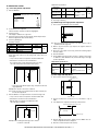
6. Environment conditions
7. IMC board functions
(1) Space required
Folded multi manual feed
Open multi manual feed
628 (W) × 585.5 (D) mm
894 (W) × 585.5 (D) mm
* Sort function
(Electronic sort)
(2) Operating ambient conditions
Humidity (%)
* Group function
Rotation copy
2 in 1/ 4 in 1
Temperature (˚C)
Edge erase
(3) Ambient storage conditions
Center erase
Binding edge
Humidity (%)
1
Humidity (%)
1
Compression memory
for electronic sort
* Memory read capacity
Memory expansion
Temperature (˚C)
32MB (Copy: 16MB, Print: 16MB)
90 sheets (max. 1500 sheets) with A4
standard documents at 600dpi. Offset
paper exit by the shifter function
32MB (Copy: 16MB, Print: 16MB)
90 sheets (max. 1500 sheets) with A4
standard documents at 600dpi. Offset
paper exit by the shifter function
If there is paper of the same size as the
document size, the image is rotated and
printed even though the paper is set in a
different direction. (In some cases,
enlargement rotation may not be executed.)
Two pages or four pages of documents are
copied on one page of paper. Division can
be made with slid lines or dotted lines (by
user setup). (The solid line width is 8 lines)
Images on the edges of the document are
erased and copy is made. (Adjustable in
the range of 0 – 20mm (0 – 1 inch).)
The center image of the set document is
erased and copy is made. (Adjustable in
the range of 0 – 20mm (0 – 1 inch).)
Binding edge is provided on the left, right
or the top of the set document.
32MB
32MB (Copy: 16MB, Print: 16MB)
90 sheets (Max. 1500 sheets) of A4
standard documents (Sharp A4 standard
document Test Chart B (6%))
2 slots for DIMM memory, Max. 512MB x 2
slots + 32MB (Expandable up to 1056MB)
Note: The number of sheets for the columns marked with “*” is calculated supposing that the same quantity is assigned to the ROPM
memory and the copy expansion memory.
AR-M256/M257/M258/M316/M317/M318/5625/5631 SPECIFICATIONS 3 - 5
8. Printer function
(AR-M256/ M257/ M316/ M317/ 5625/ 5631)
A. “Sharp Printer Language with Compression
(SPLC)” Printer function
(1) Basic specification
Item
Print Speed
Resolution
Smoothing
Toner Save Mode
Input tray
Duplex print
Finisher
Printer driver
Manual
(Online manual)
Platform
Support OS
(Printer Driver)
Detail
15ppm: 600dpi (including transfer from PC)
25ppm: ROPM (AR-M256/ M257/ 5625)
31ppm: ROPM (AR-M316/ M317/ 5631)
600dpi
600dpi
Standard
Multi Bypass tray
Tray 1, Tray 2, Tray 3, Tray 4
(Depending on conditions of the machine
and option installation.)
Standard
Option
Standard
Standard
IBM PC/ AT (Include compatible machine)
Windows 98/ Me
Windows NT 4.0 Workstation (SP5 or later)
Windows 2000
Windows XP/ XP x64
Windows Vista/ Vista x64
Content
Tray:
Normal paper, letter head
paper, recycle paper, colored
paper
Bypass:
Normal paper, recycle paper,
OHP, label paper, gift
wrapping paper, postcards,
double postal card (no folding
line), envelope, postcard
paper, coarse paper, No. 2
master drawing, thick paper
Transparency print
Yes/ No
Paper Output Output Tray Selection • Center Tray
• Upper Tray
Paper Input
Graphic
Function
Paper Type
Staple
Print Quality
Smoothing
Toner save
Photo Enhancement
Fit to Page
2 Gradation print
Image Adjustment
Watermark
Watermark
B. Printer driver specification
(1) System
Machine
IBM PC/ AT (Include
compatible machine)
Windows 98/ Me
Windows NT 4.0 Workstation (SP5 or later)
Windows 2000
Windows XP/ XP x64
Windows Vista/ Vista x64
(2) Printing function specification
General
Function
Copies
Orientation
Collate
Document Style
Paper Input
User setting
Position
OS
N-up printing
N-up Order
N-up Border
User Setting
Paper Size
Custom Paper Size
Source Selection
Content
1-999
Portrait
Landscape
Collate
Uncollate
1-Sided, 2-Sided (Book),
2-Sided (Tablet)
2/ 4
Z
Yes/ No
Yes
A3/ B4/ A4/ B5/ A5/ B6/ A6/
Ledger (11x17) /
Legal (8.5 x 14) /
Foolscap (8.5 x 13) /
Letter (8.5 x 11) /
Invoice (5.5 x 8.5)/ Folio/
Executive/ COM-10 /
DL/ C5/ 8K/ 16K
1 size
• Auto
• Bypass (Auto)
Size
Angle
Gray Scale
Edit Font
On first page only
Configuration Input Trays
Setting
Output Tray Options
Others
Set Tray Status
Version Information
ROPM
• Finisher Offset tray
Yes/ No
Normal
Draft
Photo
Yes/ No
Yes/ No
Yes/ No
Yes/ No
Yes/ No
Brightness: 0 to 100
Contrast: 0 to 100
(None)/ TOP SECRET/
CONFIDENTIAL/ DRAFT/
ORIGINAL/ COPY
Add/ Update/ Delete
Center
X: ±50
Y: ±50
6 to 300
±90
0 to 255
Yes
Yes/ No
Two/ Three/ Four trays
None/ Upper Tray/ Staple
Finisher
Yes
Yes
Yes/ No
(3) Print quality
Mode
Resolution/
Print quality
Smoothing
Toner Save Mode
Photo Enhancement
2 Gradation print
Control
600dpi
(Fixed)
On*
Off
On
Off*
On
Off*
On
Off*
Content
Print quality is selected from
Normal*/ Draft/ Photo.
Smoothing function is ON.
Smoothing function is OFF.
Toner save function is ON.
Toner save function is OFF.
Photo enhancement function is ON.
Photo enhancement function is
OFF.
2-Gradation print function is ON.
2-Gradation print function is OFF.
* Default
• Bypass (Manual)
• Tray 1/ 2/ 3/ 4
AR-M256/M257/M258/M316/M317/M318/5625/5631 SPECIFICATIONS 3 - 6
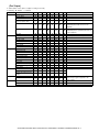
(5) Paper handling specifications
a. Paper feed direction
Limitations on tray/ functions for support paper
Paper feed tray
Paper name
A3
A4
A5
A6
B4
B5
B6
Ledger
Letter
Legal
Executive
Folio
Invoice
Foolscap
8K
16K
DL
C5
Com10
Custom
Paper size
297 x 420 mm
210 x 297 mm
148 x 210 mm
105 x 148 mm
257 x 364 mm
182 x 257 mm
128 x 182 mm
11 x 17 inch
8.5 x 11 inch
8.5 x 14 inch
7.25 x 10.5 inch
8.3 x 13 inch
5.5 x 8.5 inch
8.5 x 13 inch
270 x 390 mm
195 x 270 mm
110 x 220 mm
162 x 229 mm
4.125 x 9.5 inch
W: 100 to 297 mm
L: 148 to 431.8 mm
Manual
tray
Yes
Yes
Yes
Yes
Yes
Yes
Yes
Yes
Yes
Yes
Yes
Yes
Yes
Yes
Yes
Yes
Yes
Yes
Yes
Yes
Tray 1
Tray 2
Tray 3
Tray 4
Yes
Yes
Yes
N/A
Yes
Yes
N/A
Yes
Yes
Yes
N/A
N/A
Yes
Yes
Yes
Yes
N/A
N/A
N/A
Yes
Yes
N/A
N/A
Yes
Yes
N/A
Yes
Yes
Yes
N/A
N/A
N/A
Yes
Yes
Yes
N/A
N/A
N/A
Yes
Yes
N/A
N/A
Yes
Yes
N/A
Yes
Yes
Yes
N/A
N/A
N/A
Yes
Yes
Yes
N/A
N/A
N/A
Yes
Yes
N/A
N/A
Yes
Yes
N/A
Yes
Yes
Yes
N/A
N/A
N/A
Yes
Yes
Yes
N/A
N/A
N/A
Center
tray
Yes
Yes
Yes
Yes
Yes
Yes
Yes
Yes
Yes
Yes
Yes
Yes
Yes
Yes
Yes
Yes
Yes
Yes
Yes
N/A
N/A
N/A
N/A
Yes
Setting direction toward paper
feed port = Long side
Setting direction toward paper
feed port = Short side
Transfer direction
Transfer direction
(6) Print enable area
Actual page size
Paper
Size
A3
B4
A4
B5
A5
Ledger
Legal
Letter
Invoice
Foolscap
Folio
Executive
COM-10
C5
DL
Paper exit tray
Upper
Offset
tray
tray
Yes
Yes
Yes
Yes
Yes
N/A
N/A
N/A
Yes
Yes
Yes
Yes
Yes
N/A
Yes
Yes
Yes
Yes
Yes
Yes
Yes
N/A
Yes
N/A
Yes
N/A
Yes
Yes
Yes
Yes
Yes
Yes
Yes
N/A
Yes
N/A
Yes
N/A
N/A
Function
N/A
Staple
Fit page
Yes
Yes
N/A
N/A
Yes
Yes
N/A
Yes
Yes
Yes
N/A
N/A
N/A
Yes
N/A
N/A
N/A
N/A
N/A
Yes
Yes
Yes
Yes
Yes
Yes
Yes
Yes
Yes
Yes
Yes
Yes
Yes
Yes
Yes
Yes
Yes
Yes
Yes
N/A
N/A
A
B
C
D
E
F
G
H
7014
6070
4960
4298
3508
6600
5100
5100
3300
5100
4980
4350
2474
3826
2598
9920
8597
7014
6070
4960
10200
8400
6600
5100
7800
7800
6300
5700
5408
5196
6730
5786
4676
5770
3224
6300
4800
4800
3000
4800
4680
4050
2174
3542
2314
142
142
142
142
142
150
150
150
150
150
150
150
150
142
142
100
100
100
100
100
100
100
100
100
100
100
100
100
100
100
300
300
300
300
300
300
300
300
300
300
300
300
300
300
300
6814
5870
4760
4098
3308
6400
4900
4900
3100
4900
4780
4150
2274
3626
2398
0
0
0
0
0
0
0
0
0
0
0
0
0
0
0
Print area
Logic paper size
HP/GL
picture frame
AR-M256/M257/M258/M316/M317/M318/5625/5631 SPECIFICATIONS 3 - 7
Actual page
size
Print area
Logic paper
size
HP/GL
picture
frame
Paper
Size
A3
B4
A4
B5
A5
Ledger
Legal
Letter
Invoice
Foolscap
Folio
Executive
COM-10
C5
DL
A
B
C
D
E
F
G
M-bus
H
CCD
9920
8597
7014
6070
4960
8400
8400
6600
5100
7800
7800
6300
5700
5408
5196
7014
6070
4960
4298
3508
5100
5100
5100
3300
5100
4980
4350
2474
3826
2598
9684
8361
6778
5830
4720
8160
8160
6360
2860
7560
7560
6060
3460
5172
4960
118
118
118
118
118
120
120
120
120
120
120
120
120
118
118
100
100
100
100
100
100
100
100
100
100
100
100
100
100
100
300
300
300
300
300
300
300
300
300
300
300
300
300
300
300
9720
8397
6814
5870
4760
8200
8200
6400
4900
7600
7600
6100
5500
5208
4996
0
0
0
0
0
0
0
0
0
0
0
0
0
0
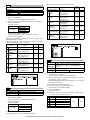
0
MCU
Print
Engine
Image
process
ASIC
CPU
IMC
CPU
Page memory
Extraction
UART
Command status
JBIG
data
JBIGLite
GDI
CPU
IEEE1284
Header + JBIG data PC
ASIC
Compressed
memory
JBIG printer driver
Data through
: Data flow
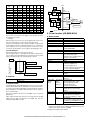
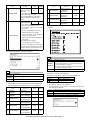
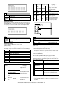
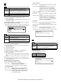
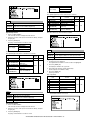
∗ Top margin
9. Printer function (AR-M258/ M318)
The set value is received from the digital copier, and data are made
according to the set value.
A. Basic function
∗ Left margin
Since the paper size sensor is not set, the digital copier cannot recognize the size and direction of paper which is actually inserted.
Therefore, the left margin is set according to the paper size specified in
the print data sent from the computer, and print process is performed.
If the computer does not specify the paper size, or in the case of the
custom size, the left margin is set according to the default paper size.
(7) Print reference
This machine employs the center reference system.
Since the digital copier is not provided with the tray size detection feature, formatting and center distribution are performed not by the actual
paper size but by the paper size specified by the computer.
Origin
Paper feed direction
ABCDEFGHIJKLMN
12345
Actual paper size
Optional memory
Toner save mode
Paper feed tray
Duplex print
Finisher
NIC
abc
Size specified by the HOST
PostScript Level3 *2
Packed software
Center reference line
Operation manual
Platform
C. Interface
Interface
Item
Print Speed
Resolution
Smoothing
Standard memory
Expansion memory*1
IEEE 1284 (Parallel interface)
USB Ver. 2.0
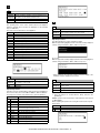
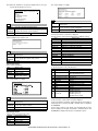
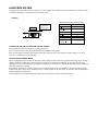
D. System outline
The GDI-PWB is provided with IEEE1284 I/F on the host side, and the
16-bit bi-directional data bus I/F and UART on the machine side. Transfer of image data with the IMC-PWB is performed with this 16-bit bidirectional data bus. Command status information with the engine is
processed with UART.
This unit is installed to the position of PCL-PWB on the conventional
AR-235/ 275.
JBIG compression data sent from the host are transferred to the IMC
PWB, where the data are extracted to be VIDEO data, and sent
through the MCU PWB to the LSU.
Support OS
(Printer
driver)
Custom PS/
PPD/
Custom
PCL5e/ 6
Only PPD
Support PDL
Installed fonts
Standard
Option
Detail
600dpi
300dpi, 600dpi
600dpi
64 MB (Standard) +256MB x 1
DIMM 1 slot
144 pin 256MB DIMM
8MB flash DIMM
Standard
Multi manual feed tray
Tray1, Tray2, Tray3, Tray4
(Depends on the installation status of
the machine and options.)
Standard
Option
Standard (AR-P27)
• 10Base-T, 100Base-TX
• Corresponding protocol:
IP/ SPX, TCP/ IP, IPV6, Comforming
to IPsec, EtherTalk, NetBEUI
Option
Printer driver, PAU4.0, Status monitor,
Installer
Standard (Online manual)
IBM PC/ AT compatible machine
Macintosh
Windows 98/ Me
Windows NT 4.0 (SP5 or later)
Windows 2000/ Server 2003
Windows XP/ XP x64
Windows Vista/ Vista x64
MacOS 9.0 to 9.2.2/ X10.1.5/ X10.2.8
MacOS 10.3.3 to 10.3.9/ X10.4/
X10.4.4
PCL5e, PCL6, PostScript Level 3,
PCL5e/PCL6:
Roman outline fonts = 80 types
Line printer font (Bitmap) = 1 type
PCL5e/PCL6:
Bar code fonts = 28 types (Can be
provided by the flash ROM kit as well)
PS3: Roman outline fonts = 136 types
*1: The network scan requires 1 slot of memory (max. 256MB). When,
therefore, the network scan is installed, the maximum memory area
available for the printer functions is 320MB.
*2: PDF print is available with PostScript.
AR-M256/M257/M258/M316/M317/M318/5625/5631 SPECIFICATIONS 3 - 8
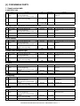
[4] CONSUMABLE PARTS
1. Supply system table
A. SEC/ SECL/ LAG
No.
Item
1 Toner cartridge
(black)
2
3
Content
Toner cartridge (With IC chip)
(Toner; Net weight 745g)
TNCA replacement operation manual
Developer (black) Developer
(Developer; Net weight 400g)
Drum
Drum
×10
Life
25K (×10)
×10
×10 25cpm: 75K (×10)
31cpm: 100K (×10)
×1
25cpm: 75K
31cpm: 100K
Model name
Remarks
AR-310MT Life setting by A4 (8.5"×11") 6% document
MT=NT*10
AR-271MD
MD=ND*10
AR-310DR
B. Europe/ East Europe/ Russia / Australia/ New Zealand
No.
Item
1 Toner cartridge
(black)
2
3
Content
Toner cartridge (With IC chip)
(Toner; Net weight 745g)
TNCA replacement operation manual
Developer (black) Developer
(Developer; Net weight 400g)
Drum
Drum
×10
Life
25K (×10)
Model name
Remarks
AR-310LT Life setting by A4 (8.5"×11") 6% document
LT=T*10
×10
×10
75K (×10)
AR-271LD
×1
75K
AR-310DM
×10
Life
25K (×10)
×10
×10
75K (×10)
AR-271CD
×1
75K
AR-310DR
×10
Life
25K (×10)
×10
×10
75K (×10)
AR-271CD
×1
75K
AR-310DR
×10
Life
25K (×10)
×10
×10
75K (×10)
AR-271LD
×1
75K
AR-310DR-T
×10
Life
25K (×10)
Model name
Remarks
AR-310CT-C Life setting by A4 (8.5"×11") 6% document
CT-C=ST-C*10
×10
×10
75K (×10)
AR-271CD-C CD-C=SD-C*10
×1
75K
×1
Life
15K (×10)
Model name
Remarks
AR-311ST-C Life setting by A4 (8.5"×11") 6% document
* Without toner save.
×1
×1
75K (×10)
AR-271SD-C
×1
75K
AR-310DR-C
LD=DV*10
C. Asia affiliates
No.
Item
1 Toner cartridge
(black)
2
3
Content
Toner cartridge (With IC chip)
(Toner; Net weight 745g)
TNCA replacement operation manual
Developer (black) Developer
(Developer; Net weight 400g)
Drum
Drum
Model name
Remarks
AR-310CT Life setting by A4 (8.5"×11") 6% document
CT=ST*10
CD=SD*10
D. SMEF/ Israel/ Philippines/ Agent
No.
Item
1 Toner cartridge
(black)
2
3
Content
Toner cartridge (With IC chip)
(Toner; Net weight 745g)
TNCA replacement operation manual
Developer (black) Developer
(Developer; Net weight 400g)
Drum
Drum
Model name
Remarks
AR-310ET Life setting by A4 (8.5"×11") 6% document
ET=FT*10
CD=SD*10
E. Taiwan
No.
Item
1 Toner cartridge
(black)
2
3
Content
Toner cartridge (With IC chip)
(Toner; Net weight 745g)
TNCA replacement operation manual
Developer (black) Developer
(Developer; Net weight 400g)
Drum
Drum
Model name
Remarks
AR-310ET Life setting by A4 (8.5"×11") 6% document
ET=FT*10
LD=DV*10
F. Hong Kong
No.
Item
1 Toner cartridge
(black)
2
3
Content
Toner cartridge (With IC chip)
(Toner; Net weight 745g)
TNCA replacement operation manual
Developer (black) Developer
(Developer; Net weight 400g)
Drum
Drum
AR-310DR-C
G. China
No.
Item
1 Toner cartridge
(black)
2
3
Content
Toner cartridge (With IC chip)
(Toner; Net weight 455g)
TNCA replacement operation manual
Developer (black) Developer
(Developer; Net weight 400g)
Drum
Drum
AR-M256/M257/M258/M316/M317/M318/5625/5631 CONSUMABLE PARTS 4 - 1
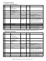
2. Maintenance parts list
A. SDSCA/ SECL/ LAG (AR-M257/ M317)
No.
1
Item
Content
4
Upper heat roller kit Upper heat roller
Fuser gear
Upper heat roller bearing
Upper cleaning pad
Fusing separation pawl (upper)
Lower heat roller kit Lower heat roller
Fusing separation pawl (lower)
Fuser bearing (lower)
150K maintenance Drum separation pawl unit
kit
Transfer roller unit
MC unit
MC unit
5
Cleaner blade
Cleaner blade
6
Drum frame unit
Drum frame unit
2
3
Life
Model
name
AR-310UH
Remarks
×1
150K
×1
×2
×1
×4
×1
300K
AR-310LH
×4
×2
×2
150K
AR-310KA1
×1
×10 25cpm: 75K (×10) AR-310MC AR-310MC = AR-310NC ×10
31cpm: 100K (×10)
The order places an order in AR-310MC.
Addition of Sterling.
×10 25cpm: 75K (×10) AR-270CB AR-270CB = AR-270BL ×10
31cpm: 100K (×10)
The order places an order in AR-270CB.
×1 25cpm: 225K
AR-310DU ∗ The life of the toner reception seat attached to
the drum frame is 225K (25cpm)/ 300K
31cpm: 300K
(31cpm), and it can be used up to 3 times.
(Supplied as a drum frame unit.)
∗ Drum frame unit contains all the drum unit
7
8
9
10
Transfer roller unit
Paper feed roller kit
Fusing unit
Staple cartridge
11 Staple cartridge
Transfer roller unit
Paper feed roller kit
Fusing unit (120V heater lamp)
Staple cartridge
×1
×1
×1
×3
150K
100K
150K
3000 staples ×3
Staple cartridge
×3
5000 staples ×3
parts excluding Drum and Drum fixing plate.
AR-310TX
AR-310IR
AR-310FU
AR-SC1 For AR-FN5A (For 30 sheets staple)
Common with the cartridge for FN4
AR-SC2 For AR-F14N (For 50 sheets staple)
Common with the cartridge for FN7
∗ The other maintenance parts than the above are supplied as service parts.
B. SEEG/ SUK/ SCA/ SCNZ/ SEA/ SEES/ SEZ/ SEIS/ SEB/ SEN/ SEF/ SMEF/ Russia/ Special country
(AR-M256/ M316, AR-5625/ 5631)
No.
1
Item
Content
4
Upper heat roller kit Upper heat roller
Fuser gear
Upper heat roller bearing
Upper cleaning pad
Fusing separation pawl (upper)
Lower heat roller kit Lower heat roller
Fusing separation pawl (lower)
Fuser bearing (lower)
150K maintenance Drum separation pawl unit
kit
Transfer roller unit
DV blade
DV side sheet N
MC unit
MC unit
5
Cleaner blade
Cleaner blade
6
Drum frame unit
Drum frame unit
2
3
Life
Model
name
AR-310UH
Remarks
×1
150K
×1
×2
×1
×4
×1
300K
AR-310LH
×4
×2
×2
150K
AR-310KA
×1
×1
×2
×10 25cpm: 75K (×10) AR-310MC AR-310MC = AR-310NC ×10
31cpm: 100K (×10)
The order places an order in AR-310MC.
Addition of Sterling.
×10 25cpm: 75K (×10) AR-270CB AR-270CB = AR-270BL ×10
31cpm: 100K (×10)
The order places an order in AR-270CB.
×1 25cpm: 225K
AR-310DU ∗ The life of the toner reception seat attached to
31cpm: 300K
the drum frame is 225K (25cpm)/ 300K
(31cpm), and it can be used up to 3 times.
(Supplied as a drum frame unit.)
∗ Drum frame unit contains all the drum unit
7
8
Transfer roller unit
Staple cartridge
Transfer roller unit
Staple cartridge
×1
×3
150K
3000 staples ×3
9
Staple cartridge
Staple cartridge
×3
5000 staples ×3
parts excluding Drum and Drum fixing plate.
AR-310TX
AR-SC1 For AR-FN5A (For 30 sheets staple)
Common with the cartridge for FN4
AR-SC2 For AR-F14N (For 50 sheets staple)
Common with the cartridge for FN7
∗ The other maintenance parts than the above are supplied as service parts.
AR-M256/M257/M258/M316/M317/M318/5625/5631 CONSUMABLE PARTS 4 - 2
C. STCL/ SRH/ SRS/ SRSSC/ SBI/ Agent (All model)
No.
Item
Content
Life
Model
name
Remarks
1
Upper heat roller kit Upper heat roller
Fuser gear
Upper heat roller bearing
Upper cleaning pad
Fusing separation pawl (upper)
×1
×1
×2
×1
×4
150K
AR-310UH
2
Lower heat roller kit Lower heat roller
Fusing separation pawl (lower)
Fuser bearing (lower)
×1
×4
×2
300K
AR-310LH
3
150K maintenance Drum separation pawl unit
kit
Transfer roller unit
DV blade
DV side sheet N
×2
×1
×1
×2
150K
AR-310KA
4
MC unit
MC unit
×10 25cpm: 75K (×10) AR-310MC AR-310MC = AR-310NC ×10
31cpm: 100K (×10)
The order places an order in AR-310MC.
Addition of Sterling.
5
Cleaner blade
Cleaner blade
×10 25cpm: 75K (×10) AR-270CB AR-270CB = AR-270BL ×10
31cpm: 100K (×10)
The order places an order in AR-270CB.
6
Drum frame unit
Drum frame unit
×1 25cpm: 225K
31cpm: 300K
AR-310DU ∗ The life of the toner reception seat attached to
the drum frame is 225K (25cpm)/ 300K
(31cpm), and it can be used up to 3 times.
(Supplied as a drum frame unit.)
∗ Drum frame unit contains all the drum unit
parts excluding Drum and Drum fixing plate.
4
Staple cartridge
Staple cartridge
×3
3000 staples ×3
AR-SC1
For AR-FN5A (For 30 sheets staple)
Common with the cartridge for FN4
5
Staple cartridge
Staple cartridge
×3
5000 staples ×3
AR-SC2
For AR-F14N (For 50 sheets staple)
Common with the cartridge for FN7
∗ The other maintenance parts than the above are supplied as service parts.
AR-M256/M257/M258/M316/M317/M318/5625/5631 CONSUMABLE PARTS 4 - 3
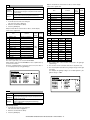
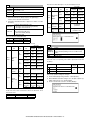
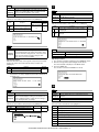
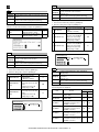
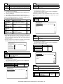
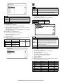
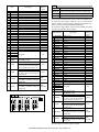
2. Production number identification
3. Environment conditions
<TD cartridge>
A. Ambient conditions for transporting
The label on the TD cartridge shows the date of production.
Date of oroduction
Version no.
Humidity (%)
Serial number
(0001-9999)
location of manufacture
Temperature (˚C)
<Drum>
The laser print indicates the date (year, month, day) of production.
Humidity (%)
B. Ambient storage conditions (sealed)
Label position
Temperature (˚C)
1
1
2
2
3
4
The last digit of the production year.
The production month.
X stands for October, Y November, and Z December.
Humidity (%)
C. Operating ambient conditions
Use environment
conditions
3, 4The production day.
Temperature (˚C)
4. Life (packed conditions)
Photoconductor drum (36 months from the production month)
Developer, toner (24 months from the production month)
AR-M256/M257/M258/M316/M317/M318/5625/5631 CONSUMABLE PARTS 4 - 4
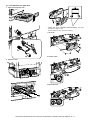
[5] UNPACKING AND INSTALLATION
• Avoid installation to a place where there is ammonium gas.
Installation near a diazo-copier may lead to dirty copy.
1. Installation
A. Environment
The performance of this machine is affected by the environment of the
installing site. Avoid installation to the following places:
• Avoid installation in direct sunlight, otherwise the plastic parts may
be deformed.
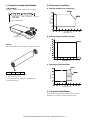
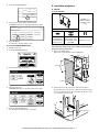
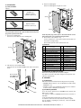
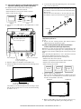
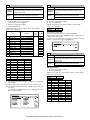
• Be sure to have enough space around the machine.
Be sure to allow the required space around the machine for servicing
and proper ventilation.
12" (30cm)
12"
(30cm)
12"
(30cm)
• Avoid installation in a place of high temperature, high humidity, low
temperature or low humidity, otherwise paper may be dampened and
frost may be generated in the machine to cause a paper jam and
dirty copy.
B. Power source
• Be sure to use only the power outlet (with the earth terminal) of 15A
or more and 100V.
• Install the machine near the power outlet to facilitate disconnection
of the power plug.
• Avoid installation in a dusty place, otherwise dust may enter the
machine to cause dirty copy or machine troubles.
• If the power plug of this machine and other illuminating apparatus
are connected to the same power outlet, the lamp may flicker. Use
an exclusive power outlet for this machine without connecting
another lamp together.
• Avoid complex wiring. Be careful not to damage, break, or process
the power cord.
• Avoid installation to a place with much vibration, otherwise the
machine may cause troubles.
• Earth wire connection
Be sure to connect the earth wire for protection against danger.
If not, improper grounding may cause a fire or an electric shock.
Earth terminal
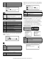
• Avoid installation to a place of poor ventilation.
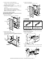
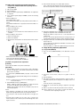
C. Transport
• When transporting the machine, use two people to lift the machine
using the two grips provided on each side of the machine.
AR-M256/M257/M258/M316/M317/M318/5625/5631 UNPACKING AND INSTALLATION 5 - 1
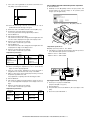
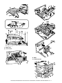
D. Other precautions
• If the machine produces smoke or bad smell, stop the operation of
the machine.
• When the exclusive table (option) is used, be sure to use the adjusters (4 pcs.) on the floor.
When it is required to move the machine for rearrangement of the
office, etc., release the adjuster locks and move the machine.
Adjuster
• Do not use flammable spray near the machine.
Lock
Release
• Do not remove the cabinet of the machine.
• Do not put a receptacle with water in it or metal pieces, which may
drop inside the machine, causing a trouble.
• The fusing section is heated to a high temperature.
When removing a paper jam, be careful not to touch the fusing section.
Fusing section
• When it thunders, turn off the power and disconnect the power plug
from the power outlet to prevent against an electric shock or a fire
caused by lighting damage.
• If a piece of metal or water enters the machine, turn off the power
and disconnect the power plug from the power outlet.
• Do not touch the power plug with a wet hand.
• When the machine is not used for a long time, disconnect the power
plug from the power outlet for safety.
• When transporting the machine, turn off the power and disconnect
the power plug from the power outlet. (Remove the earth wire after
disconnecting the power plug from the power outlet.)
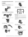
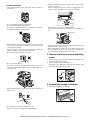
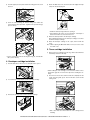
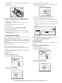
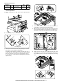
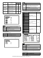
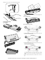
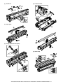
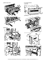
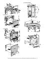
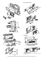
2. Removal of protective material and fixing
screw
1) Remove all tapes, then open the document cover and remove the
protective material of sheet shape.
• Do not remodel the machine.
• Be careful not to pinch your fingers when closing the front cover or
the side cover and setting the paper feed tray to supply paper or process a paper jam.
2) Use a screwdriver to remove the fixing screw.
The fixing screw is required when transporting the machine. Keep
it in the tray. (Refer to the later description.)
3. Removal and storage of fixing pin
1) Lift the knob and gently pull out the tray.
• When disconnecting the power plug from the power outlet, do not
pull the cord.
• Do not throw toner or the toner cartridge into a fire.
• Keep toner or the toner cartridge away from the children.
AR-M256/M257/M258/M316/M317/M318/5625/5631 UNPACKING AND INSTALLATION 5 - 2
2) Hold the paper pressure plate and turn the fixing pin in the arrow
direction.
4) Rotate the MG roller in the arrow direction and supply developer
evenly into the developing unit.
3) Store the removed fixing pin and the fixing screw which was
removed in the above procedure, together in the specified storage
place in the tray.
MG roller
∗ Shake the developer bag well before opening it.
∗ Check that the DV seal is free from developer. If developer is
attached to the DV seal, clean and remove it.
5) Attach the developer tank to the developer cartridge.
Fixing pin
After supplying developer into the developer cartridge, do not tilt or
shake the developer cartridge.
6) Attach the developer cartridge to the copier, and fix it with the
screw.
Note: When replacing the OPC drum with a new one, be sure to clear
the drum count.
5. Toner cartridge installation
Fixing screw
1) Remove the toner cartridge from the bag, shake it about 20 times
horizontally, and remove the tape.
∗ If power is turned don without removing the fixing pin, it will be difficult to pull out the tray.
4. Developer cartridge installation
Shake about 20 times.
Shutter
1) Hold the both sides of the front cover, and pull down to open it.
Tape
∗ When holding the toner cartridge, do not touch the shutter section,
but hold the grips. Do not remove the tape before shaking the cartridge.
2) Loosen the blue screw and pull out the developing cartridge.
2) Press the lock release lever, and insert the unit completely into the
copier along the guide groove. Then fix the blue screw and the
locking screw.
3) Remove the developer tank from the developer cartridge.
∗ Dirt or dust must be removed from the toner cartridge before
installing.
AR-M256/M257/M258/M316/M317/M318/5625/5631 UNPACKING AND INSTALLATION 5 - 3
3) Remove the tape from the shutter, and remove the shutter from the
toner cartridge.
Dispose the removed shutter.
4) Select the tray in which you loaded paper.
If the desired tray does not appear in the display, use the [↑] key or
[↓] key to scroll until it appears.
TYPE / SIZE
TRAY 1
PLAIN / 8½ x 11
TRAY 2
PLAIN / 8½ x 14
TRAY 3
PLAIN / 11x17
5) Select the size and type of paper that is loaded in the tray.
6. Toner density sensor level adjustment
1) Open the cover with the power OFF.
2) Power ON (The mechanism cannot be initialized because the
cover is open.)
3) Install the developing unit with new developer in it.
4) Enter SIM 25-2.
(# → ∗ → C → ∗ → 25 → START → 2 → START)
5) Close the cover immediately before starting the operation.
The currently selected paper type will be highlighted.
• To change the paper type selection, touch the appropriate type
key.
• To change the paper size selection, touch the appropriate size
key.
• To change the displayed size selections to AB sizes, touch [AB
↔ INCH].
CUSTOM SETTINGS
OK
TRAY 1 TYPE/SIZE SETTING
TYPE
6) Press the [START] key to start.
After completion of the adjustment, be sure to cancel the simulation.
Note: When replacing developer with new one, be sure to clear the
developer counter.
7. Tray paper size setting
SIZE
AB
INCH
PLAIN
LETTER HEAD
11x17
8½x14
8½x13
RECYCLED
COLOR
8½x11
8½x11R
5½x8½
6) Touch the [OK] key.
When you change the paper in a tray, follow the steps below to change
the tray's paper type and paper size settings.
7) A message appears prompting you to check the paper in the tray.
Check the paper and then touch the [OK] key.
The settings cannot be changed when operation has stopped because
the paper ran out or a misfeed occurred, or when an interrupt copy job
is being performed.
B. Manual feed tray
Even in copy mode, the settings cannot be changed while a print job or
received fax is being printed.
Use either of the following two methods to set the bypass tray's paper
type setting.
Note:
(1) From the [CUSTOM SETTINGS] key
• 5-1/2" x 8-1/2" (A5) size paper can only be set for tray 1.
1) Set paper on the tray.
• B5 size paper cannot be set for tray 2 (However, B5R size paper can
be set.).
2) Press the [CUSTOM SETTINGS] key.
You will return to the tray settings screen.
The custom settings menu screen will appear.
• Tray settings for trays other than the bypass tray can be prohibited in
the key operator programs.
LINE
DATA
A. Trays 1 – 4
1) Set paper on the tray.
B STATUS
CUSTOM SETTINGS
2) Press the [CUSTOM SETTINGS] key.
The custom settings menu screen will appear.
LINE
DATA
B STATUS
3) Touch the [TRAY SETTINGS] key.
CUSTOM SETTINGS
The tray settings screen will appear.
TOT L COUNT
TRAY SETTINGS
CONTRA
ADDRE
CONTRO
3) Touch the [TRAY SETTINGS] key.
KEYBOARD
SELECT
The tray settings screen will appear.
TOT L COUNT
TRAY SETTINGS
KEYBOARD
SELECT
CONTRA
ADDRE
CONTRO
KEY
AR-M256/M257/M258/M316/M317/M318/5625/5631 UNPACKING AND INSTALLATION 5 - 4
KEY
8. Installation of options
4) Touch the [BYPASS TRAY] key.
A. AR-P27
TYPE / SIZE
TRAY 4
PLAIN / 11x17
BYPASS
TRAY
PLAIN
(1) Parts included
CD-ROM: 1 pc.
Operation manual
Installation caution
sheet
5) Select the type of paper that is loaded in the tray.
"JAPANESE P/C" refers to official postcards used in Japan.
CUSTOM SETTINGS
OK
BYPASS TRAY TYPE SETTING
PCL PWB: 1 pc.
SELECT THE PAPER TYPE.
PLAIN
LETTER HEAD
ENVELOPE
RECYCLED
COLOR
LABELS
HEAVY PAPER
THIN PAPER
TRANSPARENCY
JAPANESE P/C
6) Touch the [OK] key.
You will return to the tray settings screen.
(2) From the [PAPER SELECT] key
M3 screws: 3 pcs.
(For installation of
the parallel and the
USB connectors)
M3 screws with
spring washer : 6 pcs.
(For installation of the
PCL PWB)
Support post: 2 pcs.
(2) Installation procedure
1) Set paper on the tray.
Turn off the main switch of the copier and then remove the power
plug of the copier from the outlet.
2) Touch the [PAPER SELECT] key.
1) Remove the shielding plate.
Remove five screws and remove the shielding plate.
Screws
3) Touch the paper type selection key.
Screws
4) Select the paper type.
"JAPANESE P/C" refers to official postcards used in Japan.
2) Cut and remove the cut-out portion from the left rear cabinet.
Cut and remove the cut-out portion of the left rear cabinet using a
tool such as diagonal cutters. (Be careful about the direction of the
tool so that the cut surface is flat)
5) Touch the [PAPER SELECT] key.
You will return to the main screen of copy mode.
AR-M256/M257/M258/M316/M317/M318/5625/5631 UNPACKING AND INSTALLATION 5 - 5
Cut-out portion
3) Attach the PCL PWB unit.
Attach the support post to the mounting plate of machine options.
Then connect the PCL PWB connector to the mother board connector and fit the PCL PWB with the six screws with M3 spring
washer (packed with the unit).
Then, attach the parallel and USB connector portion using the supplied three screws.
M3 screws with
spring washer
Support
post
M3 screw
Memory module
(S.O.DIMM)
B. AR-PK1N
M3 screws
(1) Parts included
CD-ROM: 1*
License agreement
Installation caution sheet
PCL PWB
M3 screws with
spring washer
4) Attach the shielding plate.
Attach the shielding plate using five screws.
*NOTE : Do not use the CD-ROM packed in AR-PK1N, but use the CDROM packed together with the AR-P27 for setting the PS
driver.
(2) Installation procedure
To enable the PS3, the product key must be acquired.
(For the method of acquiring the product key, contact the SHARP
authorized dealer.)
1) Check that AR-P27 operates normally.
• Turn on the power and wait until warming up is complete.
• Press the PRINT key on the operation panel of the main unit.
• If the LCD in the operation panel of the main unit switches to the
print mode normally, AR-P27 is operating normally.
Screws
• If it is not operating normally, follow the AR-P27 Installation Manual to check and modify the system configuration settings and
check the operation.
2) Enable the PS3.
To enable the system configuration, use the keys on the main unit
to set the mode.
Enter the product key with the key operator program. (Refer to the
Operation Manual of Key Operator Program.)
Setting of the product key is complete. To update the system, press
the CA key to exit the setting mode.
Screws
3) Check the PS3.
Make the following sequence of selections on the control panel.
Insert the power plug of the copier to the outlet and turn on the
main switch. Then, carry out the following procedure.
5) Check for the PCL PWB.
Press the PRINT key on the operation panel to check to see if the
copier enters the print mode.
6) Check for the language.
Check for the language setting (26-22) following the procedure
described in the service manual (section of simulation).
7) Check for printing.
For installation of printer drivers on a computer, see the supplied
operation manual.
Then, connect a parallel cable to the computer and execute printing to check to see if printing can be executed properly.
• Press Special Functions , highlight Configuration and press OK.
• Use the up and down keys to highlight Test print menu and press
OK.
• Use the up/down keys to highlight Configuration page and press OK.
A configuration page will be printed.
Check that the option memory capacity is 128 MB or more.
Check that the PS3 has been installed.
Please keep below important information.
This information will use for other products.
APPLICATION
NUMBER
(3) Mounting of additional memory
(After mounting it, Installation proceed to step 4.)
Insert the memory module until it clicks.
The memory module is lock when it is inserted. However, be sure to
check that the module slit is engaged with the connector rib when it is
inserted.
MACHINE
SERIAL
NUMBER
PRODUCT
KEY
AR-M256/M257/M258/M316/M317/M318/5625/5631 UNPACKING AND INSTALLATION 5 - 6
C. AR-PF1/PF2
3) Attach the shielding plate.
Attach the shielding plate using the five screws.
(1) Parts included
AR-PF1
CD-ROM: 1 pc.
Operation manual
Installation caution sheet
Screws
Bar code board: 1 pc.
AR-PF2
Operation manual
Installation caution sheet
Flash ROM board: 1 pc.
Screws
(2) Installation
Turn off the main switch of the copier and then remove the power
plug of the copier from the outlet.
1) Remove the shielding plate.
Remove five screws and remove the shielding plate.
Insert the power plug of the copier to the outlet and turn on the
main switch. Then, carry out the following procedure.
4) Check the bar codes. (AR-PF1 only)
Use the operation keys on the operation panel to print the PCL font
list from the test page printing.
Check that the optional font list is printed at the end.
(3) Font list
Screws
Screws
2) Attach the bar code board/flash ROM.
Attach the bar code board/flash ROM board to CN7 of the printer
board.
Font
No.
1
2
3
4
5
6
7
8
9
10
11
12
13
14
Font
No.
Code128TT-Regular
15
Code128-NarrowTT-Regular
16
Code128-WideTT-Regular
17
Code39HalfInch-Regular
18
Code39OneInch-Regular
19
Code39QuarterInch-Regular
20
Code39SmallHigh-Regular
21
Code39Slim-Regular
22
Code39SmallLow-Regular
23
Code39SmallMedium-Regular 24
Code39Wide-Regular
25
Codabar-Regular
26
Interleaved2of5-Regular
27
Interleaved2of5-Thin-Regular
28
Font name
Font name
OCR-A
OCR-B
OCR-B-C39-Regular
Upc-Half
Upc-Half-Bars
Upc-HalfMusic
Upc-HalfNarrow
Upc-HalfThin
Upc-Tall-Regular
Upc-TallBarsThin-regular
Upc-TallMusicThin-Regular
Upc-TallNarrow-Regular
Upc-TallThin-regular
ZipCodeBarcode-Regular
(4) Check when installing the AR-PF2
Check can be made by print out of the printer setting list.
Bar code board/
Flash ROM board/
Font ROM board
The expansion font item in the printer setting list is changed from "uninstalled" to "download font."
D. MX-NSX1
(1) Packed items
This network scanner kit includes the following items in the package.
• CD-ROM (Network Scanner Tool and Sharpdesk, Installer, Sharp
TWAIN driver, etc.)
• Installation caution sheet and Operation Manual (License numbers
of 10 user clients of Sharpdesk are specified.)
(2) Installation procedure
To use the scanner expansion kit, a S.O.DIMM memory module (128
MB or more) is needed.
If no memory is added, an S.O.DIMM module must be mounted on
PCL PWB.
For the mounting method and the memory capacity, see below.
To enable the scanner function, the product key must be acquired.
(For the method of acquiring the product key, contact the SHARP
authorized dealer.)
AR-M256/M257/M258/M316/M317/M318/5625/5631 UNPACKING AND INSTALLATION 5 - 7
1) Check the capacity of the Printer PWB memory.
Use the keys of the copier to print the configuration page.
(For details, see the operation manual.)
3) Reattach the shielding plate.
Reattach the shielding plate using the five screws.
Check that the capacity of the optional memory is 128 MB or more.
2) Enable the network scanner feature.
To enable the system configuration, use the keys on the copier to
set the mode.
Enter the product key with the key operator program.
(Refer to the Operation Manual of Key Operator Program.)
Screws
Setting of the product key is completed. Press the [EXIT] key to
update the system and exit the setting mode.
(3) Mounting the additional memory
Turn off the main switch of the copier and then remove the power
plug of the copier from the outlet.
1) Remove the shielding plate.
Remove the five screws and remove the shielding plate.
Screws
F. AR-SM5/SM6
(1) Parts included
AR-SM5
AR-SM6
256MB SDRAM memory module
(168 pin DIMM): 1 pc.
Installation caution sheet
512MB SDRAM memory module
(168 pin DIMM): 1 pc.
Installation caution sheet
Screws
Screws
(2) Installation procedure
2) Mount the memory module.
Insert the memory module until it clicks.
The memory module is lock when it is inserted. However, be sure
to check that the module slit is engaged with the connector rib
when it is inserted.
Memory module
(S.O.DIMM)
Turn off the main switch of the copier and then remove the power
plug of the copier from the outlet.
1) Remove the shielding plate.
Remove the screw and remove the cabinet.
2) Attach the SDRAM memory module.
Attach the SDRAM memory module to CN1 and CN2 of the IMC
board.
When only one SDRAM memory module is used, attach it to CN1.
CN2
CN1
AR-M256/M257/M258/M316/M317/M318/5625/5631 UNPACKING AND INSTALLATION 5 - 8
[6] EXTERNAL VIEW AND INTERNAL STRUCTURE
1. Name and function of each section
A. External view
4
2
7
3
8
1
17
9
5
6
13
12
19
10
20
14
15
11
21
18
22
16
No.
1
Name
Document cover (optional)
2
3
4
5
6
7
8
9
10
11
12
13
14
15
16
17
Document feeder tray
Original guides
Document feeder cover
Reversing tray
Exit area
Document transport cover
Document transport cover knob
Document glass
Power switch
Handles
Operation panel
Job separator tray (Upper tray)
(optional)
Center tray
Front cover
Paper trays
Upper right side cover
18
19
20
21
Side cover
Side cover handle
Bypass tray paper guides
Bypass tray
22
Bypass tray extension
Function/Operation
Presses a document.
Place the original(s) that you wish to scan face up here.
Adjust to the size of the originals.
Open to remove misfed originals.
Pull out to remove misfed originals.
Originals exit the machine here after copying.
Open to remove misfed originals.
Pull to open the document transport cover.
Place an original that you wish to scan face down here.
Press to turn the machine power on and off.
Use to move the machine.
Contains operation keys and the touch panel.
Print jobs and received faxes are delivered to this tray.
Note
Optional (AR-M256/M258/
M316/M318/5625/5631)
When the reversing single
pass feeder is installed.
(AR-M257/M317:Standard)
When the job separator
tray installed.
Finished copies are delivered to the center tray.
Open to remove paper misfeeds and perform machine maintenance.
Each tray holds 500 sheets of copy paper.
Open to remove misfeeds when an optional job separator tray kit or a
optional finisher is installed.
Open to remove misfeeds.
Pull to open the side cover.
Adjust to the width of the paper.
Regular paper and special paper (such as transparency film) can be fed
from the bypass tray.
Pull out the bypass tray extension before placing paper in the bypass tray.
AR-M256/M257/M258/M316/M317/M318/5625/5631 EXTERNAL VIEW AND INTERNAL STRUCTURE 6 - 1
B. Internal structure
1
2
6
3
4
5
No.
1
2
3
4
Name
Toner cartridge lock release lever
Toner cartridge
Roller rotating knob
Photoconductive drum
Function/Operation
Use to unlock the toner cartridge.
Contains toner.
Turn to remove misfed paper.
Copy images are formed on the photoconductive drum.
5
Fusing unit release levers
To remove a paper misfeed in the fusing unit, push up on these
levers and remove the paper.
6
Fusing unit paper guide
Open to remove misfed paper.
Note
Do not touch the photoconductive
drum (green portion). Doing so
may damage the drum and cause
smudges on copies.
The fusing unit is hot. Do not
touch the fusing unit when
removing misfed paper. Doing so
may cause a burn or injury.
AR-M256/M257/M258/M316/M317/M318/5625/5631 EXTERNAL VIEW AND INTERNAL STRUCTURE 6 - 2
C. Operation panel
COPY
PRINT
ON LINE
DATA
SCAN
DATA
LINE
DATA
FAX
JOB STATUS
CUST OM SETTINGS
AC C.#-C
1
No.
1
2
Name
Touch panel
Mode select keys and indicators
[COPY] key
[PRINT] key/ONLINE indicator/
DATA indicator
[SCAN] key/DATA indicator
[FAX] key/LINE indicator/
DATA indicator
3
4
[JOB STATUS] key
[CUSTOM SETTINGS] key
5
6
Numeric keys
[ACC.#-C] key
7
[#/P] key
8
9
[CLEAR] key
[START] key
10
11
[INTERRUPT] key
[CLEAR ALL] key
2
3
4
5
6
7
8
9
Function/Operation
The machine status, messages and touch keys are displayed on the panel. The
display will show the status of printing, copying or network scanning according
to the mode that is selected.
Use to change modes and the corresponding display on the touch panel.
Press to select copy mode.
[PRINT] key: Press to select print mode.
• ONLINE indicator: Print jobs can be received when this indicator is lit.
• DATA indicator: A print job is in memory. The indicator lights steadily while
the job is held in memory, and blinks while the job is printed.
[SCAN] key: Press to select network scan mode when the network scanner
option is installed.
• DATA indicator: Lights steadily or blinks while a scanned image is being sent.
[FAX] key: Press to select fax mode when the fax function is installed.
• LINE indicator : This lights up while faxes are being sent or received.
• DATA indicator: Blinks when a fax has been received to memory and lights
steadily when a fax is waiting in memory for transmission.
Press to display the current job status.
Use to adjust various settings of the machine including the contrast of the touch
panel and key operator programs.
Use to enter numeric values for various settings.
When auditing mode is enabled, press this key after finishing a job to return the
machine to account number entry standby.
Use this key to execute a job program in copy mode. The key is also used to
dial in fax mode.
Press to clear a copy number setting or cancel a job.
Press in copy mode, scanner mode, or fax mode to begin copying, network
scanning, or faxing.
This key blinks when auto power shut mode has activated. Press the key to
return to normal operation.
Use to perform an interrupt copy job.
Resets the settings to the initial settings.
10
11
Note
When the network
scanner option is
installed.
When the fax option is
installed.
AR-M256/M257/M258/M316/M317/M318/5625/5631 EXTERNAL VIEW AND INTERNAL STRUCTURE 6 - 3
D. Job status screen (common to copy, print, network scan and fax)
This screen appears when the [JOB STATUS] key on the operation panel is pressed.
A job list showing the current job and the stored jobs or a list showing completed jobs can be displayed.
The contents of jobs can be viewed and jobs can be deleted from the queue. The following screen shows the job queue for print jobs.
1
2
3
No.
1
Name
Job list
2
Mode switching keys
3
4
[PRINT JOB] key
[SCAN TO] key
5
6
7
[FAX JOB] key
Display switching keys
[STOP/DELETE] key
8
[PRIORITY] key
9
[DETAIL] key
4
5
6
Function/Operation
Shows stored jobs and the job currently being executed. Touch one of
keys 3 to 5 in the above illustration to select the type of job. The icon
next to each job name indicates the mode of the job as follows:
Copy mode
Printer mode
Network scanner mode
Fax mode (Send jobs)
Fax mode (Receive jobs)
The jobs in the job list appear in the form of keys. To give priority to a
job or pause or delete a job, touch the key of the job and then use the
key described in 7 or 8.
Use to select the job list mode: "JOB QUEUE" (Stored/currently
executing jobs) or "COMPLETE" (Finished jobs).
"JOB QUEUE": Shows jobs that have been stored and the job that is
currently being executed.
"COMPLETE" : Shows the jobs that have been finished. Note that
copy jobs do not appear in this list.
If the power is turned off, or if auto power shut-off
mode activates when there are no jobs, the jobs in
the "COMPLETE" list will be erased.
Use to view the list of output jobs for all modes (print, copy, and fax).
Displays a network scanner job.
This displays stored fax jobs and the fax job currently being executed.
Use to change the page of the displayed job list.
Use to pause or delete a job currently being executed, or to delete a
stored job. Copy jobs and received faxes cannot be paused or deleted
with this key. Copy jobs can be canceled by pressing the [CLEAR] key
or [CLEAR ALL] key.
Touch this key after selecting a stored job in this [JOB QUEUE] list to
print the job ahead of the other jobs.
Shows information on the selected job. This cannot be used for a
received fax.
7
8
9
Note
* 1 :"PAPER EMPTY" in the job status
display
"PAPER EMPTY" in the job status display
indicates that the machine is out of the
specified size of paper. Add the specified
size of paper. If the specified size of paper
is not available and you are in printer mode,
another size of paper can be loaded in the
bypass tray to allow printing to take place.
When the network scanner function is
installed.
When the fax option is installed.
AR-M256/M257/M258/M316/M317/M318/5625/5631 EXTERNAL VIEW AND INTERNAL STRUCTURE 6 - 4
E. Motor, Solenoid, Clutch
F. Sensor
1
2
1
3
30
4
5
2
3
4
6
5
21
6
21
7
8
9
20
19
10
11
6
7
8
9
29
10
11
12
27
18
26
25
17
13
14
15
28
24
23
16
15
22
14 13 12
21
20
No.
1
2
3
4
Name
Mirror motor
Shifter motor
Paper exit gate
switching solenoid
Duplex motor
5
DUP-2 motor
6
7
8
9
10
Cooling fan
Main motor
PS clutch
Paper feed clutch
Manual paper feed
solenoid
Paper feed transfer
clutch
2nd cassette paper
feed clutch
Cassette lift-up motor
Cassette lift-up motor
2nd cassette paper
feed solenoid
Paper feed solenoid
11
12
13
14
15
16
17
18
19
20
21
Toner motor
Separation pawl
solenoid
Exhaust fan motor
Intake fan motor
Fusing paper exit fan
Code
MIRM
SFTM
OGS
Function and operation
Optical mirror base drive
Shifter drive
Paper exit gate switcher
DPXM
Duplex paper switching
and exit motor
Reverse pass for paper
transport
Cools the inside of the unit.
Main drive
Main unit paper feed
Paper feed roller drive
Manual paper feed
solenoid
Paper feed transfer clutch
VFM
MM
RRC
CPFS1
MPFS
TRC2
No.
1
2
3
4
5
6
7
8
9
CPFS2
10
LUM1
LUM2
CPFC2
CPFC1
TM
PSPS
DCFM
DCFM2
VFM2
Cassette paper lift-up
Cassette paper lift-up
Solenoid for the paper feed
from the cassette
Solenoid for the paper feed
from the cassette
Toner supply
Separation pawl operation
solenoid
Cools the inside of the unit.
Cools the inside of the unit.
(31 sheet model)
11
12
13
14
15
16
17
18
19
20
Name
Mirror home position
sensor
Document cover
sensor
Document size
sensor
19
31 18
Code
MHPS
17 16
Function and operation
Mirror (scanner) home
position detection
OCSW Document cover open/close
detection
DSIN3 Document size detection
(Inch series: PD3, 4)
(AB series: PD4, 5)
2nd paper exit sensor POD2 2nd paper exit detection
2nd paper exit full
TOPF 2nd paper exit section full
detection sensor
detection
Right cabinet door
DSWR0 Right cabinet door open/
switch
close detection
1st paper exit sensor
POD1 1st paper exit detection
Shifter home position SFTHP Shifter home position sensor
sensor
detection
Paper exit sensor
PPD2 Paper exit detection
(DUP side)
Thermistor
Fusing temperature
detection
Thermostat
Abnormal high temperature
detection in the fusing section
1st cassette (paper
CD1
1st cassette (paper tray)
tray) detection
empty detection
Manual feed paper
PPD1L Sensor of paper entry from
entry sensor
the manual paper feed tray,
the 2nd/multi-stage desk, or
the DUP
Manual paper feed
MPLS2 Manual feed tray position
tray empty sensor 2
detection
Manual paper feed
MPLS1 Manual feed tray position
tray empty sensor 1
detection
Manual feed length
MPLD1 Manual feed paper length
detection sensor 1
detection
Manual feed length
MPLD2 Manual feed paper length
detection sensor 2
detection
Manual feed paper
MPED Manual feed paper empty
empty sensor
detection
Door switch
DSWR1 Front door and side door
open/close detection
2nd right door switch DSWR2 Side door open/close
detection
AR-M256/M257/M258/M316/M317/M318/5625/5631 EXTERNAL VIEW AND INTERNAL STRUCTURE 6 - 5
No.
21
22
23
24
25
26
27
28
29
30
31
Name
2nd cassette paper
pass sensor
2nd cassette paper
upper limit detection
sensor
2nd cassette paper
empty sensor
1st cassette paper
pass sensor
1st cassette paper
upper limit detection
sensor
1st cassette paper
empty sensor
Toner sensor
Center tray paper
YES/NO sensor
Main switch
Original size sensor
Reverse pass paper
detection sensor
Code
PFD2
Function and operation
2nd cassette paper pass
LUD2
2nd cassette paper upper
limit detection
H. Section
1
2
3
4
6
23
7
PED2
2nd cassette paper empty
detection
PPD1H 1st cassette paper pass
8
LUD1
1st cassette paper upper
limit detection
9
10
11
12
13
14
PED1
1st cassette paper empty
detection
Toner density detection
LOEMP Center tray paper YES/NO
detection
PSSW Main power switch
DSIN0 Document size detection
(Inch series: PD1, 2)
(AB series: PD1 – 3)
DUP2 Reverse pass detection
16
17
18
19
22
No.
1
2
G. PWB unit
1
Name
Copy lamp
Copy lamp unit
2
3
LSU unit
4
Lens unit
5
MC holder unit
6
7
8
Paper exit roller
Transport roller
Upper heat roller
9
Lower heat roller
10
11
12
13
Drum unit
DUP transport follower
roller
DUP transport roller
Transport roller
14
Resist roller
15
16
Manual feed tray
Manual paper feed roller
17
Manual feed transport
roller
1st cassette pick-up roller
1st cassette paper feed
roller
2nd cassette pick-up
roller
2nd cassette paper feed
roller
MG roller
2nd/3rd mirror unit
3
11
4
10
5
6
9
8
7
No.
1
2
3
4
5
6
Name
Inverter PWB
CCD PWB
Option connector PWB
IMC PWB
MCU PWB
Mother board
7
8
9
10
11
Tray interface PWB
DC power supply PWB
High voltage PWB
KEY PWB
OPU PWB
5
Function and operation
Copy lamp control
For image scanning (read)
Image process
Main unit control
Connection with FAX PWB and
PCL PWB
2nd tray control
DC voltage control
High voltage control
Operation panel control
18
19
20
21
22
23
15
21 20
Function and operation
Image radiation lamp
Operates in synchronization with
2nd/3rd mirror unit to radiate
documents sequentially.
Converts image signals into laser
beams to write on the dum.
Reads images with the lens and
the CCD.
Supplies negative charges evenly
on the drum.
Paper exit roller
Paper transport roller
Fuses toner on paper.
(with the Teflon roller)
Fuses toner on paper.
(with the silicone rubber roller)
Forms images.
Duplex paper transport
Duplex paper transport
Transfer images on the drum onto
paper.
Synchronize the paper lead edge
with the image lead edge.
Manual feed paper tray
Picks up papers in manual paper
feed port.
Transports paper from the manual
paper feed port.
Picks up paper from the cassette.
Transports the picked up paper to
RESIST section.
Picks up paper from the cassette.
Transports the picked up paper to
RESIST section.
Puts toner on the OPC drum.
Reflects the images from the copy
lamp unit to the lens unit.
AR-M256/M257/M258/M316/M317/M318/5625/5631 EXTERNAL VIEW AND INTERNAL STRUCTURE 6 - 6
[7] ADJUSTMENTS, SETTING
1. List of adjustment items
A
Section
Process section
B
Mechanism section
Adjustment item
Developing doctor gap adjustment
MG roller main pole position adjustment
Developing bias voltage adjustment
Grid bias voltage adjustment (High mode)
Grid bias voltage adjustment (Low mode)
Print start position adjustment
RSPF image lead edge position adjustment
Rear edge void adjustment
Paper off center adjustment
Left edge void area adjustment
Main scanning direction (FR direction) distortion
balance adjustment
(1)
(2)
(3)
(4)
(5)
(1)
(2)
(3)
(4)
(5)
(6)
(7)
(8)
(9)
(10)
(11)
(12)
(13)
(14)
C
Image density
(exposure) adjustment
(15)
(1)
Sub scanning direction (scanning direction)
distortion adjustment
Main scanning direction (FR direction) distortion
balance adjustment
Main scanning direction (FR direction)
magnification ratio adjustment
Sub scanning direction (scanning direction)
magnification ratio adjustment
Off center adjustment (RSPF mode)
OC (RSPF) open/close detection position
adjustment
Original sensor adjustment
RSPF white correction pixel position adjustment
(required in an RSPF model when replacing the
lens unit)
RSPF scan position auto adjustment
Copy mode
2. Copier adjustment
Adjustment procedure/SIM No.
Developing doctor gap adjustment
MG roller main pole position adjustment
SIM8-1
SIM8-2
SIM8-3
SIM50-5
SIM50-6
SIM50-1
SIM50-10
SIM50-1-8
No. 2/3 mirror base unit installing position
adjustment
Copy lamp unit installing position adjustment
Winding pulley position adjustment
Rail height adjustment
SIM48-1-1
a
b
OC mode in copying (SIM 48-1-2)
RSPF sub scanning direction magnification ratio
(SIM48-1-3, 48-1-4)
SIM50-12
SIM41-3
SIM41-2, 41-4 (41-1)
SIM63-7
SIM53-8
SIM46-2
(2) MG roller main pole position adjustment
1) Put the developing unit on a flat surface.
A. Process section
2) Tie a needle or pin on a string.
(1) Developing doctor gap adjustment
1) Loosen the developing doctor fixing screw A.
2) Insert a thickness gauge of 1.5mm to the three positions at 20mm
and 150mm from the both ends of the developing doctor as shown.
150mm
3) Hold the string and bring the needle close to the MG roller horizontally. (Do not use paper clip, which is too heavy to make a correct
adjustment.) (Put the developing unit horizontally for this adjustment.)
4) Do not bring the needle into contact with the MG roller, but bring it
to a position 2 or 3mm apart from the MG roller. Mark the point on
the MG roller which is on the extension line from the needle tip.
20mm
5) Measure the distance from the marking position to the top of the
doctor plate of the developing unit to insure that it is 18mm.
10mm
10mm
R
20mm
DG:1.5 -+0.1
0.15
C
If the distance is not within the specified range, loosen the fixing
screw A of the main pole adjustment plate, and move the adjustment plate in the arrow direction to adjust.
A
DG:1.55 -+0.15
0.2
F
DG:1.5 -+0.1
0.15
A
A
3) Tighten the developing doctor fixing screw.
4) Check the clearance of the developing doctor. If it is within the
specified range, then fix the doctor fixing screw with screw lock.
∗ When inserting a thickness gauge, be careful not to scratch the
developing doctor and the MG roller.
<Adjustment specification>
Developing doctor gap
+0.1mm
F/R both ends (20mm from the both ends):1.5 -0.15mm
C (Center)(150mm from the both ends):
1.55
+0.15mm
-0.2mm
AR-M256/M257/M258/M316/M317/M318/5625/5631 ADJUSTMENTS, SETTING 7 - 1
A
(3) Developing bias voltage adjustment (SIM 8-1)
SIMULATION 8-1
8-1
SIMULATION
DV BIAS COPY SETTING. INPUT VALUE 200-550, AND PRESS
START.
1: AE
426
426
2: TEXT
450
1/1
3: TEXT/PHOTO
450
4: PHOTO
450
5: SUPER/PHOTO
400
6: TONER SAVE
376
2) Touch the exposure mode to be changed.
The current set value is displayed.
Setting
range
Item
Content
4
PHOTO (145)
Photo (145mm/s)
6 (–605V)
5
TONER SAVE
(145)
Toner save
(145mm/s)
2 (–505V)
6
AE (122)
AE (122mm/s)
3 (–530V)
7
TEXT (122)
Character
(122mm/s)
8
TEXT/PHOTO
(122)
Character/Photo
(122mm/s)
5 (–580V)
9
PHOTO (122)
Photo (122mm/s)
5 (–580V)
10
TONER SAVE
(122)
Toner save
(122mm/s)
2 (–505V)
1) Execute SIM 8-1.
1-12
Default
5 (–580V)
3) Enter the set value with the 10-key.
Min. unit: –25V increment
4) Press the [START] key.
(5) Grid bias voltage adjustment (Low mode) (SIM 8-3)
Output is made with the entered value, and the display returns to
the original state.
1) Execute SIM 8-3.
<Adjustment specification>
Item
1
AE (145)
2
TEXT (145)
6
TEXT/PHOTO
(145)
PHOTO (145)
TONER SAVE
(145)
AE (122)
7
TEXT (122)
3
4
5
8
9
10
TEXT/PHOTO
(122)
PHOTO (122)
TONER SAVE
(122)
SIMULATION 8-3
Content
AE (145mm/s)
Character
(145mm/s)
Character/Photo
(145mm/s)
Photo (145mm/s)
Toner save
(145mm/s)
AE (122mm/s)
Character
(122mm/s)
Character/Photo
(122mm/s)
Photo (122mm/s)
Toner save
(122mm/s)
Setting
range
Default
450 (–450V)
500 (–500V)
500 (–500V)
500 (–500V)
200650
400 (–400V)
2) Touch the exposure mode to be changed.
The current set value is highlighted.
400 (–400V)
3) Enter the set value with the 10-key.
450 (–450V)
450 (–450V)
4) Press the [START] key.
Output is made with the entered value for 30sec, and the display
returns to the original state.
<Adjustment specification>
450 (–450V)
Item
Content
375 (–375V)
(4) Grid bias voltage adjustment (High mode) (SIM 8-2)
1
AE (145)
2
TEXT (145)
1) Execute SIM 8-2.
6
TEXT/PHOTO
(145)
PHOTO (145)
TONER SAVE
(145)
AE (122)
7
TEXT (122)
3
SIMULATION 8-2
4
5
8
9
2) Touch the exposure mode to be changed.
The current set value is displayed.
10
3) Enter the set value with the 10-key.
TEXT/PHOTO
(122)
PHOTO (122)
TONER SAVE
(122)
AE (145mm/s)
Character
(145mm/s)
Character/Photo
(145mm/s)
Photo (145mm/s)
Toner save
(145mm/s)
AE (122mm/s)
Character
(122mm/s)
Character/Photo
(122mm/s)
Photo (122mm/s)
Toner save
(122mm/s)
Min. unit: -25V increment
4) Press the [START] key.
Output is made with the entered value for 30sec, and the display
returns to the original state.
<Adjustment specification>
Item
Content
1
AE (145)
AE (145mm/s)
2
TEXT (145)
Character
(145mm/s)
3
TEXT/PHOTO
(145)
Character/Photo
(145mm/s)
Setting
range
Default
4 (–555V)
1-12
6 (–605V)
6 (–605V)
AR-M256/M257/M258/M316/M317/M318/5625/5631 ADJUSTMENTS, SETTING 7 - 2
Setting
range
Default
4 (–455V)
6 (–505V)
6 (–505V)
6 (–505V)
2 (–405V)
1-12
3 (–405V)
5 (–455V)
5 (–455V)
5 (–455V)
2 (–380V)
B. Mechanism section
<Adjustment specification>
Adjustment
mode
Main cassette
lead edge void
Print start
position
(1) Print start position adjustment
1) Execute SIM 50-5.
SIMULATION 50-5
LEAD EDGE ADJUSTMENT(PRINT). INPUT VALUE 0-99, AND PRESS
START.
1: TRAY1
53
53
2: OPTION
53
1/1
3: MANUAL
53
4: DUPLEX
53
SIM
50-1
-2
50-5
Spec value
Setting
range
Lead edge void:
1 – 4mm
Image loss: 3mm
or less
1 – 99
Set value
B/0.127
99 – H/0.127
[H: Print start position measurement value (mm),
B: Lead edge void (mm)]
(2) RSPF image lead edge position adjustment
1) Set a scale on the OC table as shown below.
2) Touch the item to be adjusted.
The item and the currently set value are highlighted.
3) Press the [P] key.
The display is shifted to the copy menu.
4) Select the paper feed tray, the print density, and the duplex mode.
Enter the adjustment value with the 10-key.
5) Press the [START] key.
Copying is started.
1
2
3
4
Item
TRAY1
OPTION
MANUAL
DUPLEX
Content
1st cassette
Option cassette
Manual feed
Back print
Setting range
0-99
1-99
Default
53
6) Measure the distance H between the paper lead edge and the
image print start position. Set the image print start position set
value again.
• 1 step of the set value corresponds to about 0.127mm shift.
• Calculate the set value from the formula below.
99 – H/0.127 (mm) = Image print start position set value
<H: Print start position measurement value (mm)>
0mm
0mm
5
Note: Since the printed copy is used as a test chart, put the scale in
paralleled with the edge lines.
2) Make a copy, then use the copy output as an original to make an
RSPF copy again.
3) Check the copy output. If necessary, perform the following adjustment procedures.
4) Execute SIM 50-6.
5) Set the RSPF lead edge position set value so that the same image
is obtained as that obtained in the previous OC image lead edge
position adjustment.
<Adjustment specification>
Adjustment
mode
RSPF
image lead
edge
position
SIM
Set value
Spec value
50-6
1 step:
0.127mm
shift
Lead edge void:
1 – 4mm
Image loss: 3mm or less
Setting
range
1 – 99
(3) Rear edge void adjustment
10
1) Set a scale as shown in the figure below.
A4 (8.5" x 11")
∗ Fit the print edge with the paper edge, and perform the lead
edge adjustment.
Example:99 – 5/0.127 = 99 – 39.4 = about 59
Note: FIf the set value is not obtained from the above formula, perform the fine adjustment.
7) Execute SIM 50-1-2 to adjust the main cassette lead edge void.
• 1 step of the set value corresponds to about 0.127mm shift.
• Calculate the set value from the formula below.
B/0.127 (mm) = Lead edge void adjustment value
<B: Lead edge void (mm)>
Paper rear edge
2) Set the document size to A4 (8.5" x 11"), and make a copy at
100%.
3) If an adjustment is required, follow the procedures below.
Void amount (Standard value: 4mm or less)
2.5mm
5
2.5mm
Scale image
Paper rear edge
10
Example: When setting the lead edge void to 2.5mm:
2.5 /0.127 = about 20
4) Execute SIM 50-1 and set the density mode to DEN-B. The currently set adjustment value is displayed.
5) Enter the set value and press the start key.
AR-M256/M257/M258/M316/M317/M318/5625/5631 ADJUSTMENTS, SETTING 7 - 3
(5) Left edge void area adjustment
The correction value is stored and a copy is made.
<Adjustment specification>
Adjustment
mode
Rear edge
void
SIM
50-1-6
Spec
value
4mm or
less
Set value
1 step: 0.127mm
shift
Setting
range
1 – 99
Note: Before performing this adjustment, be sure to check that the
paper off center adjustment (SIM 50-10) is completed.
1) Execute SIM 50-1.
SIMULATION 50-1
LEAD EDGE ADJUSTMENT. INPUT VALUE 1-99, AND PRESS START.
(4) Paper off center adjustment
1) Set a test chart (UKOG-0089CSZZ) on the document table.
2) Select a paper feed port and make a copy.
1: RRC-A
43
2: DEN-A
18
3: DEN-A -MANUAL
18
4: DEN-A -OPTION
18
5: DEN-A -DUPLEX
18
6: DEN-B
7: DEN-B-DUP
50
8: SIDE VOID
18
9: SIDE VOID-DUP
18
10: LOSS(OC)
3
3
43
1/1
3) Execute SIM 50-10.
OK
SIMULATION 50-10
PRINT OFF-CENTER ADJUSTMENT. INPUT VALUE 1-99, AND
2) Note down the adjustment value of SIM 50-5 (Items 1, 2, 3, 4), and
change the value to 99.
PRESS START.
1: BYPASS
50
50
2: TRAY1
50
1/1
3: TRAY2
50
4: TRAY3
50
5: TRAY4
50
6: DUPLEX
50
3) Set SIM 50-1 (Items 2, 3, 4, 5) to 1. (By setting to 1, there is no
void.)
4) Place a chart with a clear lead edge (or a ruler) on the OC document table.
OK
5) Use SIM 50-1 (Item 1) to execute test print. Check the print out and
adjust so that the lead edge image is printed. (1 – 99: About
0.127mm/Step)
4) Touch the item to be adjusted.
The item and the currently set value are highlighted.
6) Reset the adjustment values of SIM 50-5 (Items 1, 2, 3, 4) to the
original values, and execute test print. Check the print out and
adjust so that the lead edge image is printed on the lead edge of
paper. (1 – 99: About 0.127mm/Step).
5) Press the [START] key.
The display is shifted to the copy menu.
6) Select the paper feed tray and the print density.
Enter the adjustment value with the 10-key.
7) Adjust SIM 50-1 (Items 2, 3, 4, 5) so that the lead edge void on the
print out is the specified value. (1 – 99: About 0.127mm/Step)
7) Press the [START] key.
Copying is started.
1
2
3
4
5
6
Item
BYPASS
TRAY1
TRAY2
TRAY3
TRAY4
DUPLEX
Content
Manual paper feed
1st cassette
2nd cassette
3rd cassette
4th cassette
Back print
Setting range
Default
9) Similar to procedure 7, adjust SIM 50-1 (Item 8, 9) so that the left
edge void is the specified value. (1 – 99: About 0.127mm/Step)
1-99
50
Second
print surface
off-center
SIM
Set value
50-10
-2
Add 1: 0.127mm
shift to R side.
50-10
-6
Reduce 1:
0.127mm shift to L
side.
10) Make an enlargement copy (400%), and check that there is no
shade of the cabinet printed at the lead edge.
11) If there is a shade printed at the lead edge in procedure 9, adjust
SIM 50-1 (Item 10). (1 – 5: About 0.677mm)
* If there is no problem, set to 3.
<Adjustment specification>
Adjustment
mode
Paper off
center
8) Similar to procedure 7, adjust SIM 50-1 (Item 6, 7) so that the rear
edge void is the specified value. (1 – 99: About 0.127mm/Step)
Spec value
Single:
Center
±2.0mm
Duplex:
Center
±2.5mm
Setting
range
Item
1
RRC-A
2
DEN-A
3
DEN-A-MANUAL
4
DEN-A-OPTION
5
DEN-A-DUPLEX
6
7
DEN-B
DEN-B-DUP
8
SIDE VOID
9
SIDE VOID-DUP
1 – 99
10 LOSS(OC)
Content
Original scan start position
adjustment
Lead edge position
adjustment value (OC)
Lead edge cancel
adjustment (Main cassette)
Lead edge cancel
adjustment
(Manual feed cassette)
Lead edge cancel
adjustment (Option cassette)
Lead edge cancel
adjustment
(back of the machine)
Rear edge void adjustment
Rear edge void adjustment
(Duplex)
Left edge void adjustment
(First print surface)
Left edge void adjustment
(Duplex)
Image loss amount
adjustment (Lead edge
image loss set value) (OC)
AR-M256/M257/M258/M316/M317/M318/5625/5631 ADJUSTMENTS, SETTING 7 - 4
Setting
Default
range
1-99
43
1-99
18
1-99
18
1-99
18
1-99
18
1-99
1-99
30
50
1-99
18
1-99
18
1-5
3
<Adjustment specification>
Adjustment
mode
Left edge void
SIM
50-1
-8
Set value
1 step: 0.127mm
shift
Spec
value
0.5 – 4mm
Setting
range
1 – 99
(6) Main scanning direction (FR direction) distortion
balance adjustment
1) Remove the OC glass, the right cabinet and the upper right side
cover.
4) Loosen the set screw of the scanner drive pulley which is not in
contact with No. 2/3 mirror base unit positioning plate.
5) Without moving the scanner drive pulley shaft, manually turn the
scanner drive pulley until the positioning plate is brought into contact with No. 2/3 mirror base unit, then fix the scanner drive pulley.
2) Loosen the copy lamp unit wire fixing screw.
Wire fixing screw
3) Manually turn the mirror base drive pulley and bring No. 2/3 mirror
base unit into contact with the positioning plate.
At that time, if the front frame side and the rear frame side of No. 2/
3 mirror base unit are brought into contact with the positioning
plate at the same time, the mirror base unit parallelism is proper.
If one of them is in contact with the positioning plate, perform the
adjustment of 4).
6) Put No. 2/3 mirror base unit on the positioning plate again, push
the projections on the front frame side and the rear frame side of
the copy lamp unit to the corner frame, and tighten the wire fixing
screw.
AR-M256/M257/M258/M316/M317/M318/5625/5631 ADJUSTMENTS, SETTING 7 - 5
(7) Sub scanning direction (scanning direction) distortion
adjustment (Winding pulley position adjustment)
This adjustment must be performed in the following cases:
• When the mirror base drive wire is replaced.
• When the lamp unit, or No. 2/3 mirror holder is replaced.
• When a copy as shown is made.
Lb
La
4) Loosen the mirror base drive pulley fixing screw on the front frame
side or on the rear frame side.
• When La < Lb
Turn the mirror base drive pulley on the front frame side in the
arrow direction A. (Do not move the mirror base drive pulley shaft.)
• When La > Lb
Turn the mirror base drive pulley on the rear frame side in the
arrow direction A. (Do not move the mirror base drive pulley shaft.)
Rear side
A
Paper exit
direction
Original
B
Copy
1) Set A3 (11" x 17") white paper on the original table as shown
below.
Front side
5) Tighten the fixing screw of the mirror base drive pulley.
<Adjustment specification>
Place a little clearance from
the rear side original guide.
La = Lb
6) Execute the main scanning direction (FR) distortion balance
adjustment previously described in 2) again.
(8) Main scanning direction (FR direction) distortion
balance adjustment (Rail height adjustment)
When there is no skew copy in the mirror base scanning direction and
there is no horizontal error (right angle to the scanning direction), the
adjustment can be made by adjusting the No. 2/3 mirror base unit rail
height.
Before performing this adjustment, be sure to perform the horizontal
image distortion adjustment in the laser scanner section.
Glass holding plate
A3 (11" x 17") white paper
Fit the paper edge and
the glass holding plate edge.
This adjustment must be performed in the following cases:
• When the mirror base wire is replaced.
• When the copy lamp unit and no. 2/3 mirror unit are replaced.
2) Open the original cover and make a normal (100%) copy.
• When the mirror unit rail is replaced and moved.
3) Measure the width of the black background at the lead edge and at
the rear edge.
• When a following copy is made.
Original
Copy A
Copy B
1) Make an original for the adjustment.
Make test sheet by drawing parallel lines at 10mm from the both
ends of A3 (11" x 17") white paper as shown below. (These lines
must be correctly parallel to each other.)
Parallel line
Parallel line
Paper exit direction
La: Lead edge black background width
Lb: Rear edge black background width
10mm
10mm
10mm
10mm
If the width (La) of the black background at the lead edge is equal
that (Lb) at the rear edge, there is no need to execute the following
procedures of 4) – 7).
White paper
2) Make a normal (100%) copy of the test sheet on A3 (11" x 17")
paper. (Fit the paper edge and the glass holding plate edge.)
AR-M256/M257/M258/M316/M317/M318/5625/5631 ADJUSTMENTS, SETTING 7 - 6
3) Measure the distances (La, Lb, Lc, Ld) at the four corners as
shown below.
La
1) Put a scale on the original table as shown below.
Lc
Paper exit
direction
2) Execute SIM 48-1.
Lb
Ld
When La = Lb and Lc = Ld, no need to perform the procedures 4)
and 5).
4) Move the mirror base B rail position up and down (in the arrow
direction) to adjust.
3) After warm-up, shading is performed and the current set value of
the main scanning direction magnification ratio is displayed on the
display section in 2 digits.
4) Manual correction mode (SIM48-1-1)
Enter the set value and press the start key.
The correction value is stored and a copy is made.
<Adjustment specification>
Note: A judgment must be made with 200mm width, and must not be
made with 100mm width.
Adjustment
mode
Main scanning
direction
magnification
ratio
Spec value
At normal:
±1.0%
SIM
481-1
Set value
Add 1: 0.1%
increase
Reduce 1: 0.1%
decrease
Setting
range
1 – 99
(10) Sub scanning direction (scanning direction)
magnification ratio adjustment
(SIM 48-1-2, SIM 48-1-3)
a. OC mode in copying
Note: Execute the procedure after completion of SIM 48-1-1.
1) Put a scale on the original table as shown below, and make a normal (100%) copy.
• When La > Lb
Shift the mirror base B rail upward by the half of the difference of
La–Lb.
• When La < Lb
Shift the mirror base B rail downward by the half of the difference
of Lb–La.
Example: When La = 12mm and Lb = 9mm, shift the mirror base
B rail upward by 1.5mm.
• When Lc >Ld
Shift the mirror base B rail downward by the half of the difference
of Lc–Ld.
• When Lc < Ld
When Lc < Ld, move the mirror base B on the paper feed side
upward.
∗ When moving the mirror base rail, hold the mirror base rail with
your hand.
<Adjustment specification>
La = Lb, Lc = Ld
5) After completion of adjustment, manually turn the mirror base drive
pulley, scan the mirror base A and mirror base B fully, and check
that the mirror bases are not in contact with each other.
∗ If the mirror base rail is moved extremely, the mirror base may be in
contact with the frame or the original glass. Be careful to avoid this.
(9) Main scanning direction (FR direction) magnification
ratio adjustment (SIM 48-1)
2) Compare the scale image and the actual scale.
If necessary, perform the following adjustment procedures.
3) Execute SIM 48-1-2.
4) Enter the set value and press the start key.
The set value is stored and a copy is made.
<Adjustment specification>
Adjustment
mode
Sub scanning
direction
magnification
ratio (OC mode)
Spec value
SIM
Set value
At normal:
±1.0%
48-12
Add 1:
0.05% increase
Reduce 1:
0.05% decrease
Setting
range
1 – 99
b. RSPF mode in copying
Note: Before performing this adjustment, be sure to check that the
CCD unit is properly installed and that OC mode adjustment in
copying has been completed.
Note: Before performing this adjustment, be sure to check that the
CCD unit is properly installed.
AR-M256/M257/M258/M316/M317/M318/5625/5631 ADJUSTMENTS, SETTING 7 - 7
1) Put a scale on the original table as shown below, and make a normal (100%) copy to make a test chart.
(12) OC (RSPF) open/close detection position adjustment
1) Execute SIM 41-3.
2) Gradually close the OC (RSPF) from the full open position, and
measure distance A when the display on the operation panel
changes. (See the figure below.)
Distance A = Table glass top - OC (RSPF) handle rib
Note: Since the printed copy is used as a test chart, put the scale in
parallel with the front side edge of the glass.
2) Set the test chart on the RSPF and make a normal (100%) copy.
3) Compare the scale image and the actual image.
If necessary, perform the following adjustment procedures.
4) Execute SIM 48-1-3.
5) After warm-up, shading is performed.
The current front surface sub scanning direction magnification ratio
correction value is displayed in two digits on the display section.
A
6) Enter the set value and press the start key.
The set value is stored and a copy is made.
7) Execute SIM 48-1-4.
The current back surface sub scanning direction magnification ratio
is displayed in two digits on the display section.
8) Enter the set value and press the start key.
The set value is stored and a copy is made.
Sub scanning
direction
magnification ratio
(RSPF mode)
Spec
value
At normal:
±1.0%
SIM
Set value
48-1-3
48-1-4
Add 1:
0.05% increase
OC (SPF) open/close position A: 125 – 225mm
3) If the distance is outside the specified range, adjust the open/close
sensor attachment plate position as shown below.
<Adjustment specification>
Adjustment mode
<Adjustment specification>
Setting
range
1 – 99
・ Distance < 125mm: Shift toward A.
・ Distance > 225mm: Shift toward B.
Reduce 1:
0.05% decrease
(11) Off center adjustment (RSPF mode)
A
Note: Before performing this adjustment, be sure to check that the
paper off center is properly adjusted.
1) Place the center position adjustment test chart (sheet with a
straight line in the scan direction at the center) on the RSPF.
2) Make a normal copy from the manual paper feed tray, and check
the printed copy with the test chart.
B
If any adjustment is required, perform the following procedure.
3) Execute SIM 50-12.
4) After warm-up, shading is performed and the current set value of
the off center adjustment is displayed on the display section in 2
digits.
5) Enter the set value and press the start key.
The set value is stored and a copy is made.
1) Set A3 (11" x 17") paper on the OC table.
(Keep the SPF (OC cover) open.)
2) Execute SIM 41-2.
3) Keep A=125mm, and execute SIM 41-4. (Do not put paper on the
table.)
<Adjustment specification>
Adjustment
mode
Original off
center mode
(RSPF
mode)
(13) Original sensor adjustment (SIM 41-2, 41-4)
Spec value
SIM
Set value
Single: Center
± 3.0mm
Duplex: Center
±3.5mm
50-12
Add 1: 0.1mm
shift to R side
Reduce 1: 0.1mm
shift to L side
Setting
range
1 – 99
4) Check the reaction with SIM 41-1.
AR-M256/M257/M258/M316/M317/M318/5625/5631 ADJUSTMENTS, SETTING 7 - 8
(14) RSPF white correction pixel position adjustment
(required in an RSPF model when replacing the lens
unit) (SIM63-7)
3) Check that the lead edge is not shifted. (Both surfaces)
(If the original lead edge adjustment has been made properly, even
when the scan position is shifted, it is followed automatically.)
1) Fully open the RSPF.
2) Execute SIM 63-7.
3) When the operation panel displays "COMPLETE," the adjustment
is completed.
Place only the black
chart on the OC glass.
For the RSPF standard-provision
machine, check that the black
chart covers the SPF glass.
4) If the operation panel displays "ERROR," perform the following
measures.
• When the display is 0:
Check that the SPF is open.
Check that the lamp is ON. (If the lamp is OFF, check the MCU connector.)
Check that the CCD harness is properly inserted into the MCU connector.
Placing the black chart
The black chart must cover
this area.
• When the display is 281 or above:
1) Remove the table glass.
2) Remove the dark box.
3) Slide the lens unit toward the front side and attach it, then execute SIM.
• When the display is 143 or below:
1) Remove the table glass.
2) Remove the dark box.
3) Slide the lens unit toward the rear side and attach it, then execute
SIM.
F
R
4) Change the adjustment value of the RSPF scan end position.
(Change the adjustment value of SIM50-6-3 from 50 to 36.)
Change the number of steps for Pin off – scan end position from
1,014 to 986.
Be sure to execute this adjustment because an image may be cut
off during FAX transmission though copying is normally performed.
5) Change the initial value of the RSPF exposure adjustment (SIM4620) from 50 to 53.
(For the CCD exposure adjustment with RSPF, use the value of the
OC adjustment value +3.)
There are suffixes of –1 SPF and –2 RSPF. Change each of them.
C. Image density (exposure) adjustment
(1) Copy mode (SIM46-2)
1) Set a test chart (UKOG-0162FCZZ) on the OC table as shown
below.
Rear
∗ When the lens unit is moved, execute the OC main scanning magni-
fication ratio auto adjustment, SIM 48-1-1.
∗ This adjustment is basically O.K. with SIM 63-7.
(15) RSPF scan position auto adjustment
[Function]
Used to adjust the RSPF scan position automatically.
[Operation]
1) With the RSPF or the OC cover open, place a chart of black background on the OC glass. (In the RSPF standard model, the RSPF
glass surface is included.)
∗ Use a black chart (UKOG-0011QSZZ) or prepare a chart as shown
below.
Chart size: 310 x 470, prepared with cutting sheet No. 791 (Black) or
an equivalent one.
Reason: To prevent erroneous detection by disturbing light of a
fluorescent lamp, etc.
Front
2) Place three or more sheets of A3 (11" x 17") paper on the test
chart.
3) Execute SIM 46-2.
4) After warm-up, shading is performed and the current set value of
the density (exposure) level is displayed on the display section in 2
digits.
2) Enter SIM53-08, and press [START] button.
Outline of SIM: The optical unit is shifted to recognize the boundary between the OC glass and the RSPF glass cover.
With the same position as the reference, the RSPF scan position is
automatically adjusted.
5) Change the set value with the [10-key] to adjust the copy image
density.
<Note>
Note: Place originals in the rear reference, and the test chart in the
front reference when adjusting the exposure.
• After completion of the RSPF scan position auto adjustment, the
RSPF lead edge adjustment must be executed. (Both surfaces)
For mode selection, use the [10-key].
6) Make a copy and check that the specification below is satisfied.
• There must be no other sheet than the black chart on the glass surface.
• Especially when in RSPF scan, the center area is scanned in the
main scan direction. Be careful to prevent external light from entering the scan area.
AR-M256/M257/M258/M316/M317/M318/5625/5631 ADJUSTMENTS, SETTING 7 - 9
<Adjustment specification>
Density mode
AUTO
TEXT
TEXT/PHOTO
PHOTO
AE (TONER
SAVE)
TEXT (TONER
SAVE)
TEXT PHOTO
(TONER SAVE)
Exposure
level
–
1.0
Sharp Gray
Chart output
"3" is copied.
"7" is copied.
3.0
"3" is copied.
5.0
"2" is copied.
1.0
"6" is copied.
3.0
"3" is copied.
5.0
"2" is copied.
1.0
"5" is copied.
3.0
"3" is copied.
5.0
"2" is copied.
–
"3" is copied.
1.0
"7" is copied.
3.0
"3" is copied.
5.0
"2" is copied.
1.0
"6" is copied.
3.0
"3" is copied.
5.0
"2" is copied.
Set value
Setting
range
If too bright,
increase the
quantity displayed
on the copy
quantity display.
If too dark,
decrease the
quantity displayed
on the copy
quantity display.
0 – 99
AR-M256/M257/M258/M316/M317/M318/5625/5631 ADJUSTMENTS, SETTING 7 - 10
[8] SIMULATION
(Diagnostics, setup, adjustment value input, data display)
1. Outline and purpose
2. Code-type simulation
The simulation has the following functions to grasp the machine operating status, identify the trouble position and causes in an earlier stage,
and make various setups and adjustments speedily for improving the
serviceability of the machine.
A. Operating procedures and operations
1) Various adjustments
2) Setup of specifications and functions
3) Canceling troubles
* Entering the simulation mode
1) #/P key (program) ON → Asterisk (*) key ON → CLEAR key ON →
Asterisk (*) key ON → Ready for input of a main code of simulation
2) Entering a main code with the 10-key → START key ON
3) Entering a sub code with the 10-key → START key ON
4) Select an item with the scroll key and the item key.
4) Operation check
5) Various counters check, setup, and clear
6) Machine operating status (operation history) data check, clear
7) Transfer of various data (adjustments, setup, operations, counters)
The operating procedures and the displays differ depending on the
form of the operation panel of the machine.
5) The machine enters the mode corresponding to the selected item.
Press START key to start the simulation operation.
To cancel the current simulation mode or to change the main code
and the sub code, press the CUSTOM SETTINGS key.
* Canceling the simulation mode to return to the normal mode
1) Press CLEAR ALL key.
B. How to change the simulation adjustment value
set by the touch panel in the adjustment value
entry process
(1) Target SIM list
3-7, 8-1, 8-2, 8-3, 8-10, 8-11, 8-12, 9-5, 43-1, 44-34, 46-2, 46-9, 46-10,
46-11, 46-18, 46-20, 46-30, 46-31, 48-1, 48-2, 50-1, 50-5, 50-6, 50-10,
50-12, 51-1, 51-2, 51-9, 53-7
(2) Touch panel operating procedure
• In the adjustment value setup menu, the selected item is highlighted.
Change is made to the highlighted simulation adjustment value.
• If all the list of the adjustment items is not shown on one page, touch
[↑] and [↓] button to shift the page.
• To change an adjustment value, touch the select the item to change
the adjustment value. (The selected item is highlighted.) Enter the
adjustment value and perform one of the following procedures, and
the display of the adjustment value of the selected item is renewed
as well as the adjustment value.
1) Touch [OK] button.
2) Touch another selected item to change the selection state.
3) If all the list of the adjustment items cover two or more pages,
touch [↑] and [↓] button to shift the page.
4) Press [START] key.
* For simulations which allow confirmation print, copying is started
after changing the adjustment value.
(46-2, 46-9, 46-10, 46-11, 46-18, 48-1, 48-2, 50-1, 50-5, 50-6, 50-10,
50-12, 51-2, the bold-faced items in the above list.)
* If the entry value is outside the adjustable range, an error buzzer
sounds and the adjustment value is not renewed. Page shift is not
made, either.
AR-M256/M257/M258/M316/M317/M318/5625/5631 SIMULATION 8 - 1
START (Normal mode)
L1
Press the #/P key.
∗ In the cause of SIM which is set by touch panel, the
changed content can be stored by the following key, touch.
[OK] key
Other item selection
↑ ↓ key
Press the START key.
·
·
·
Press the asterisk (*) key.
1
Press the clear key.
The changed content
is stored.
4
Press the asterisk (*) key.
Do you
want to end the
simulation ?
Standby for entry of
SIM code.
YES
Press the clear all key.
NO
Enter the main code of
SIM with the 10-key.
The simulation mode
is canceled.
The main code of SIM
is displayed.
Returns to START
(Normal mode).
3
Do you want
to perform another
simulation ?
Press the START key.
NO
2
YES
Is there a sub code ?
NO
Press the CUSTOM
SETTINGS key
YES
Standby for entry of
SIM sub code.
YES
Is it the same
simulation ?
Enter the sub code of
SIM with the 10-key.
3
NO
2
Press the CUSTOM
SETTINGS key
Press the START key.
Is there a item
selection?
NO
4
YES
Select the mode and the
item with the ↑ ↓ key
and the item key.
YES
Operation check ?
Press the START key.
NO
Operation is made according
to the selected mode and item.
Operating conditions
check ?
YES
If "Operation condition check"
refer to "Sensor display", this
process is not necessary.
Press the START key.
NO
Operation is made according
to the selected mode and item.
Data clear ?
NO
Press the START key.
Select "YES".
NO
The selected mode and
the item are cleared.
Adjustments
or setting (counter data
change) ?
NO
YES
The display is made according
to the selected mode and the item.
Do you
want to change the
content ?
YES
Operation is made according
to the select ed mode and the it
(Other modes)
NO
1
Enter the new setting and
adjustment values.
L1
AR-M256/M257/M258/M316/M317/M318/5625/5631 SIMULATION 8 - 2
3. Simulation code list
Code
Main
Sub
1
1
2
1
2
2
3
2
3
6
3
7
10
11
2
4
3
1
5
2
3
1
6
2
7
1
6
8
1
2
3
8
10
11
12
13
Code
Main
Sub
Function
Used to check the operation of the scanner unit
and its control circuit.
Used to check the operation of sensor and detector
in the scanning (read) section and the related circuit.
Used to check the operation of the RSPF unit and
the related circuit.
Used to check the operation of sensors and detectors
in the RSPF unit and the related circuit.
Used to check the operation of the loads in the
RSPF unit and the control circuits.
Used to check the operation of sensor and detector
in the finisher and the related circuit.
Used to check the operation of the load in the
finisher and the control circuit.
Used to adjust the alignment position (side
regulation plate, rear edge regulation plate) for
each paper size.
Shifts to the specified paper size position.
Used to adjust the offset tray operations.
Used to make each adjustment of the saddle finisher.
Used to check the shifter operation.
Reciprocating operations are continuously
performed or the home position is checked.
(The shifter is shifted to the home position or
moved in one way by the specified steps.)
Used to check the operation of sensor and detector
in the option cassette and the related circuit.
Used to check the operation of the load in the
option tray and the control circuit.
Used to check the operation of the display (LED),
LCD in the operation panel, and control circuit.
Used to check the operation of the heater lamp and
the control circuit.
Used to check the operation of the copy lamp and
the control circuit.
Used to check the operation of the loads (clutches
and solenoids) in the paper transport system and
the control circuit.
Used to check the operation of each fan motor and
its control circuit.
Used to set the aging operation conditions.
Used to set the cycle of intermittent aging.
Used to set the display of the warm-up time.
Used to check and adjust the operation of the
developing bias voltage in each copy mode and the
control circuit.
Used to check and adjust the operation of the main
charger grid voltage (high mode) in each copy
mode and the control circuit.
Used to check and adjust the operation of the main
charger grid voltage (low mode) in each copy mode
and the control circuit.
Used to check and adjust the operation of the
developing bias voltage in each printer mode and
the control circuit.
Used to check and adjust the operation of the main
charger grid voltage (high mode) in each printer
mode and the control circuit.
Used to check and adjust the operation of the main
charger grid voltage (low mode) in each printer
mode and the control circuit.
Used to check and adjust the operation of the
developing bias voltage in FAX mode and the
control circuit.
14
8
15
1
9
4
5
10
0
14
0
16
17
21
0
0
1
1
2
3
4
5
6
22
7
8
9
10
11
12
13
19
1
2
3
24
4
5
6
7
Function
Used to check and adjust the operation of the main
charger grid voltage (high mode) in FAX mode and
the control circuit.
Used to check and adjust the operation of the main
charger grid voltage (low mode) in FAX mode and
the control circuit.
Used to check and adjust the operation of the load
(motor) in the duplex section and the control circuit.
Duplex motor RPM setting
Used to adjust the timing of switching from normal
rotation to reverse rotation or from reverse rotation
to normal rotation of the duplex motor.
Used to check the operation of the toner motor and
its control circuit.
Used to cancel excluding the self-diag U2/PF
troubles.
Used to cancel the self-diag U2 trouble.
Used to cancel the self diag “PF” trouble.
Used to set the maintenance cycle.
Used to check the counter value of each section.
Used to check the total numbers of misfeed and
troubles. (When the number of misfeed is
considerably great, it is judged as necessary for
repair. The misfeed rate is obtained by dividing this
count value with the total counter value.)
Used to check the misfeed positions and the
number of misfeed at each position.
(When the number of misfeed is considerably
great, it can be judged as necessary for repair.)
Used to check the total trouble (self diag) history.
Used to check the ROM version of each unit
(section).
Used to print each key operator setting, the
account information, and the machine adjustment
values.
Used to display the key operator code. (Use when
the customer key operator code is forgotten.)
Used to display the original, staple counter.
Used to check the number of use of each paper
feed section. (the number of prints)
Used to check the system configuration.
Used to display the FAX send/receive counter
(FAX reception and print counter).
Used to check the misfeed positions and the
number of misfeed at each position.
(When the number of misfeed is considerably
great, it can be judged as necessary for repair.)
Used to display the CRUM type.
Used to display the scanner counter in the network
scanner mode.
Used to clear the misfeed counter, the misfeed
history, the trouble counter, and the trouble history.
(The counters are cleared after completion of
maintenance.)
Used to clear the number of use (the number of
prints) of each paper feed section.
Used to clear the number usage data of the stapler,
RSPF, and scanning.
Used to reset the maintenance counter.
Used to reset the developer counter.
(The developer counter of the DV unit which is
installed is reset.)
Used to clear the copy counter.
Used to clear the OPC drum (membrane decrease)
correction counter. (This simulation is executed
when the OPC drum is replaced.)
AR-M256/M257/M258/M316/M317/M318/5625/5631 SIMULATION 8 - 3
Code
Main
Sub
9
24
10
15
1
25
2
1
2
3
5
6
10
12
14
18
22
30
35
26
36
41
46
50
57
60
71
72
27
1
5
Function
Used to clear the printer counter and other
counters. (The counter is cleared after completion
of maintenance.)
FAX counter data clear
Used to clear the scanner counter in the network
scanner mode.
Used to check the operation of the main drive
(excluding the scanner section) and to check the
operation of the toner concentration sensor.
(The toner concentration sensor output can be
monitored.)
Used to make the initial setting of toner
concentration when replacing developer.
Used to set whether the job separator is installed
or not. (Since this cannot be detected by hardware
detection, it is set in this simulation.)
Used to set whether the automatic detection of
paper size is made or not.
Used to set the specifications of the auditor.
Setting must be made depending on the use
condition of the auditor.
Used to set the count mode of the total counter and
the maintenance counter.
Used to set the specifications depending on the
destination.
Network scanner trial mode setting
Used to input the Software Key for E-MAIL RIC.
Used to input the Software Key for the PS
extension kit.
Used to set enable/disable of toner save operation.
Used to set the specification (language display) for
the destination.
Used to set ON/OFF of the heater lamp slow-up
control conforming to the CE mark control.
Used to set whether the same continuous troubles
are displayed as one trouble or the series of
troubles with SIM 22-4 when the same troubles
occur continuously.
Used to set whether the machine is stopped or not
when the maintenance counter life is expired.
Used to set ON/OFF of the automatic magnification
ratio selection (AMS) when setting the binding
function.
Used to set whether to meet with the output
direction of images regardless of the mode when
installing the finisher.
Used to set ON/OFF of the black and white
reversion function.
Used to set the model code.
Used to set enable/disable of the FAX mode key
when FAX is not installed. (When FAX is installed,
the FAX mode is enabled regardless of this setup.)
In the power save time setting, the pre-heat (preheat mode setting) and the auto power shut off
time can be set to the short time setup (pre-heat: 1
min, auto power shut off: 4 min) and the long time
setup (pre-heat: 15min, auto power shut off:
60min).
The letterhead support is set.
When “Letterhead paper setting” is selected, the
set value of SIM 26-46 (Image output direction
setting) is set to “Setting Enable” accordingly.
Used to set PC/MODEM communication trouble
(U7-00) detection Yes/No.
Used to set the tag number.
Code
Main
Sub
1
30
2
1
40
2
3
1
2
41
3
4
1
43
10
1
2
3
9
14
44
16
17
34
40
2
9
10
46
11
12
13
14
Function
Used to display the sensor status attached to the
machine.
Used to display the status of the sensors attached
to the standard cassette and the manual feed tray.
(Use SIM 4-2 for the option cassettes.)
The sensor of an uninstalled cassette is not
displayed.
Used to check the sensor of the machine manual
feed tray.
Used to adjust the manual paper feed tray paper
width detector detection level.
The AD conversion value of manual feed width
detection is displayed.
Used to check the document size detection photo
sensor.
Used to adjust the detection level of the document
size photo sensor.
Used to check the light reception level and the
detection level of the original size detection photo
sensor.
Used to adjust the detection level of OC 20
degrees.
Used to set the fusing temperature in 600dpi, or
postcard print.
Used to set the paper feed cycle timing when
printing postcards.
Used to make various setups in each mode of
process control.
Used to set the drum count correction.
Used to set the DV count correction.
Used to display the process control correction
information.
Used to display the environment (temperature,
humidity) correction information.
The correction value for the toner density reference
value corresponding to the DV count value is set
individually for 145mm/s and 122mm/s (for the 31sheet machine and the 25-sheet machine).
Used to display the toner density control reference
value.
Used to set the transfer current value in each
mode.
Used to set the time from the start of the main
motor rotation (Ready) to the start of toner supply
in previous rotation after turning on the power.
Used to set the exposure level in each exposure
mode.
Used to adjust the shift amount and the inclination
value for each level (1 to 5) of the exposure mode
(Text).
Used to adjust the shift amount and the inclination
value for each level (1 to 5) of the exposure mode
(Text/Photo).
Used to adjust the shift amount and the inclination
value for each level (1 to 5) of the exposure mode
(Photo).
FAX exposure level adjustment
(1 mode automatic adjustment)
FAX exposure level adjustment
(Normal mode individual adjustment)
FAX exposure level adjustment
(Fine text mode individual adjustment)
AR-M256/M257/M258/M316/M317/M318/5625/5631 SIMULATION 8 - 4
Code
Main
Sub
15
16
18
19
46
20
30
31
39
1
2
48
3
8
9
1
5
6
50
8
9
10
12
1
2
51
8
9
6
7
53
8
55
1
61
1
Function
FAX exposure level adjustment
(Super Fine mode individual adjustment)
FAX exposure level adjustment
(Ultra Fine mode individual adjustment)
Used to adjust inclination for each exposure mode.
Used to set the control method of the exposure
mode.
Used to set the exposure correction value of SPF/
RSPF for OC exposure.
Used to set the AE and the limit value in AE
(Toner save).
Used to set the AE and the limit value in AE
(Toner save).
Used to switch the FAX send image quality.
Used to adjust the copy mode magnification ratio
(main scanning direction, sub scanning direction).
Used to adjust the scanner mode magnification
ratio (main/sub scanning direction).
Used to adjust the print mode magnification ratio
correction.
Magnification correction adjustment (print)
FAX magnification adjustment (print)
Used to adjust the copy lead edge position.
Used to adjust the print image position (top margin)
on the print paper in the print mode.
Used to adjust the print image position (top margin)
on print paper in the copy mode. (RSPF)
FAX lead edge adjustment (read)
FAX lead edge adjustment (print)
Used to adjust the print image center position.
(Adjustment can be made for each paper feed
section.)
Used to adjust the print image center position.
(Adjustment can be made for each document mode.)
Used to adjust the OPC drum separation pawl ON time.
Used to adjust the contact pressure of paper onto
the resist roller in each section (copier paper feed
section, duplex paper feed section, RSPF paper
feed section). (When the print image position
varies greatly for the paper or when a lot of paper
jam troubles occur, the adjustment is required.)
Used to set the OPC drum separation pawl
operation inhibit. (ON/OFF)
Used to adjust the OPC drum separation voltage
ON/OFF timing.
Used to adjust the detection level of the RSPF
width. The adjustment method is the 4-point
system. Set the guide to Max. (A3/WLetter)
position, A4R/Letter R position, A5R/Invoice R
position, and Min. position for adjustment.
Used to enter the RSPF width detection
adjustment value.
Used to adjust the RSPF scan position of the
mirror unit automatically. For the RSPF scan
position automatic adjustment, the mirror unit is
shifted to 11mm before the RSPF glass cover
edge, and is operated automatically to scan
images by the unit of 1 step, detecting the position
up to the glass cover automatically.
(Adjustment value)
Default: 50, Adjustment range: 1-99
Adjustment unit: 1 = about 0.12mm
Used to set the soft switch.
Used to check the LSU (polygon motor) operation.
Check speed can select 145mm/s or 122mm/s
individually.
Code
Main
Sub
1
63
7
64
1
1
65
2
5
1
2
3
4
5
6
7
10
11
12
66
13
14
15
16
17
18
19
20
21
24
30
31
32
33
34
37
41
1
11
14
15
67
17
18
20
Function
Used to check the result of shading correction.
(The shading correction data are displayed.)
Used to adjust the RSPF white correction start
pixel position automatically.
This adjustment is performed after the lens unit is
replaced.
Used to check the operation of the printer function
(auto print operation).
Used to adjust the touch panel (LCD display
section) detection position.
Used to check the touch panel (LCD display
section) detection position adjustment result.
Used to check the key inputs of the operation panel.
Used to change and check the FAX-related soft SW.
Used to clear the FAX-related soft SW.
(Except for the FAX adjustment values)
FAX PWB memory check
Signal send mode (Signal send level: Max.)
Signal send mode (Signal send level soft SW setting)
Printing the confidential password
Print the screen memory contents
Image data memory clear
Used to send 300bps signals.
(Signal send level: Max.)
Used to send 300bps signals.
(Signal send level: Set by soft SW)
Used to register the dial numbers.
Used to perform the dial test. (10 PPS send test)
Used to perform the dial test. (20 PPS send test)
Used to perform the dial test. (DTFM signal send test)
Used to check the DTFM signal send operation.
(Signal send level: Max.)
Used to check the DTFM signal send operation.
(Signal send level: Set by soft SW.)
Used to write the SRAM data to the Flash ROM.
Used to write the Flash ROM data to the SRAM.
FAX information print
Used to clear the FAST storage data. (SEC only)
Used to set the TEL/LIU.
Used to set the TEL/LIU.
Receive data check
Signal detection check
Communication time measurement display
Speaker sound volume adjustment
CI signal check
Used to execute read/write check of the RAM on
the PCL board, and to display the result.
Used to set the select-in signal of the Centro port.
Used to check write/comparison of flash programs.
Used to check the validity of the ROM on the PCL
board and the result is displayed.
Used to clear the printer section setting.
(NVRAM clear)
Used to clear the data area for FLASH ROM
Network Scanner Application.
Used to check the network connection when the
scanner option is installed.
AR-M256/M257/M258/M316/M317/M318/5625/5631 SIMULATION 8 - 5
4. Details
2
2-1
1
1-1
Purpose
Function
(Purpose)
Section
Item
Operation test/check
Used to check the operation of the scanner unit and its
control circuit.
Optical (Image scanning)
Operation
Purpose
Function
(Purpose)
Section
Item
Operation test/check
Used to check the operation of the RSPF unit and the
related circuit.
RSPF
Operation
Operation/procedure
Enter the number of operations, and set the magnification ratio and the
original size.
Operation/procedure
1. Select the desired item, and press the [START] key.
Enter the number of operations, and set the magnification ratio and the
original size.
2. Enter the set value with the 10-key, and press the [START] key.
1. Select the desired item, and press the [START] key.
The scan counter is displayed during execution.
The RSPF unit operates at the speed corresponding to the set value.
2. Enter the set value with the 10-key, and press the [START] key.
The scanner unit operates at the speed corresponding to the set value.
Set magnification ratio
The scan counter is displayed during execution.
Document size
Duplex
Set number of times
Set magnification ratio
Document size
Set number of times
25% to 400% (1% increment)
(Default 100%)
Varies depending on the destination.
1 to 999 (0: Continuous operation)
50% to 200% (1% increment)
(Default 100%)
Varies depending on the destination.
Selectable only when RSPF is installed.
1 to 999 (0: Continuous operation)
Note: Executable only when the RSPF is installed.
2-2
1-2
Purpose
Function
(Purpose)
Section
Item
Operation test/check
Used to check the operation of sensor and detector in
the scanning (read) section and the related circuit.
Optical (Image scanning)
Operation
Operation/procedure
The status of sensors and detectors in the scanner section is displayed. The active sensors and detectors are highlighted.
MHPS
Mirror home position sensor
Purpose
Function
(Purpose)
Section
Item
Operation test/check
Used to check the operation of sensors and detectors
in the RSPF unit and the related circuit.
RSPF
Operation
Operation/procedure
The operations of sensors and detectors in the RSPF section are displayed.
The active sensors and detectors are highlighted.
(For the original size, the detection result of the original size displayed
on the copy menu is highlighted.)
EMPS
DLS1
DLS2
FGOD
DFD
RDD
OPCLS
SWD_LEN
SWD_A/D
Original empty sensor
Original length sensor (Small)
Original length sensor (Large)
RSPF paper feed cover open/close sensor
RSPF paper entry sensor
RSPF original exit sensor
Book sensor
Original detection width sensor
(Unit of 0.1mm. “Width x 10” is displayed. Example: For
300mm, 3000 is displayed.)
Original detection width sensor A/D value
RSPF width detection size (One of the following is displayed.)
A4/A3, LT/WLT, B5/B4, INV/LTR, A5/A4R, B5R, EXTRA, 8K/16K, 16KR
Note: Executable only when the RSPF is installed.
AR-M256/M257/M258/M316/M317/M318/5625/5631 SIMULATION 8 - 6
When AR-F14N is installed
2-3
Purpose
Function
(Purpose)
Section
Item
Operation test/check
Used to check the operation of the loads in the RSPF
unit and the control circuits.
RSPF
Operation
Operation/procedure
Select the load to be checked with the 10-key, and press the [START] key.
The motor for 10sec, the solenoid ON for 500msec, OFF for 500msec.
(20 times)
1
2
3
4
5
6
Item
DTM-F
DTM-R
DFCL
CLH
GSOL
RSOL
Content
RSPF motor forward rotation
RSPF motor reverse rotation
RSPF paper feed clutch
RSPF PS clutch
Document exit gate solenoid
Document exit pressure solenoid
Note: Executable only when the RSPF is installed.
FSSS
FJS
FFDSW
FTCS
FFDS
FSPS
FSUC
FSS
FSTHPS
FSHPS
FLE
FLLLS
FULS
FFE
FFES
FFRHPS
FFHPS
FFPS
FSLS
FBES
Stapler safety switch
Joint switch
Front door switch
Upper cover sensor
Front door sensor
Self prime sensor
Stapler connection detection
Stapler sensor
Stapler HP sensor
Slide HP sensor
Lift lock sensor
Lift lower limit sensor
Lift upper limit sensor
Book making clock sensor
Book making paper sensor
Book making roller HP sensor
Book making HP sensor
Book making position sensor
Paper surface sensor
Tray paper sensor
When AR-F14N/Punch unit is installed
3
3-2
Purpose
Function
(Purpose)
Section
Item
Operation test/check
Used to check the operation of sensor and detector in
the finisher and the related circuit.
Finisher
Operation
FPE
FPSHPS
FPUC
FPDS
FPDSS4
FPDSS3
FPDSS2
FPDSS1
FPTS
Punch motor encoder
Punch side resist home position
Punch connection detection
Punch dust sensor
Punch side resist sensor 4
Punch side resist sensor 3
Punch side resist sensor 2
Punch side resist sensor 1
Punch timing sensor
Note: Executable only when the finisher is installed.
Operation/procedure
Used to display the operations of sensors and detectors in the finisher
section.
The active sensors and detectors are highlighted.
When AR-FN5A is installed
INPD
FWPS
JGHP1
JGHP2
JGPD
T1OD
T1PF
PGOP
T2OD
OFHP
T2UP
T2DN
JGDSW
EVRE
STHP
READY
LSTS
NCTS
STND
T2PUD
Finisher paper entry sensor
Paper width sensor
Side guide plate HP sensor
Rear edge plate HP sensor
Tray paper empty sensor
1st tray exit sensor
1st tray paper full sensor
JAM processing PG open/close detection sensor
2nd tray exit sensor
Offset HP sensor
Tray position sensor (upper)
Tray position sensor (lower)
Tray jam processing interlock
Lift-up drive control sensor
Staple HP sensor
Self priming sensor
Staple empty sensor
Cartridge empty sensor
Staple supply cover open/close sensor
2nd tray upper surface sensor
3-3
Purpose
Function
(Purpose)
Section
Item
Operation test/check
Used to check the operation of the load in the finisher
and the control circuit.
Finisher
Operation
Operation/procedure
Select the load to be checked with the 10-key, and press the [START] key.
The finisher main motor operates for 10sec, the staple motor 5 times,
the tray lift-up motor one reciprocating operation, other motors max. 20
reciprocating operations from the home position, the solenoid repeats
500msec ON and 500msec OFF 20 times.
The staple operation motor operates only when there is no cartridge
installed.
When AR-FN5A is installed
1
2
3
4
5
6
Item
JGM1
JGM2
FM-600
FM-1200
EVM
OFM
Content
Side guide plate drive motor
Rear edge plate drive motor
Finisher main motor (600dpi)
Finisher main motor (1200dpi)
Tray lift-up motor
Tray offset motor
AR-M256/M257/M258/M316/M317/M318/5625/5631 SIMULATION 8 - 7
7
8
9
10
11
12
13
14
Item
STM
OGSLR
OGSLL
JGSL1
JGSL2
SHTSL
T2SCL
STGSL
There are 6 adjustment values for the side guide plate, and 12 for the
rear guide plate. The adjustment position is determined from the table
below according to the paper size.
Content
Staple operation motor
Transport selection gate solenoid (R)
Transport selection gate solenoid (L)
Rear edge plate drive solenoid
Upper alignment plate drive solenoid
Shutter drive solenoid
Paper exit roller clutch
Paper holding solenoid
Paper size
Side guide plate
adjustment value number
A3
A4
B4
B5
A4R
WLT
LT
LG
FC
LTR
8K
16K
1
1
3
3
5
2
2
4
4
4
6
6
When AR-F14N is installed
1
Item
FFC
2
FPSM
3
FPNM
4
5
6
7
8
9
10
11
12
FLM
FFSM
FSM
FRJM
FFJM
FAM
FPM
FFM
FJM
Content
Folding clutch
Punch side resist motor (Execution is possible only
when the punch unit is installed.)
Punch motor (Execution is possible only when the
punch unit is installed.)
Shift motor
Stapler motor
Slide motor
Alignment motor R
Alignment motor F
Bundle exit motor
Paddle motor
Transport motor
Interface transport motor
Adjustment value number
of the rear edge guide
plate
2
9
3
10
6
1
8
4
5
7
11
12
Note: Executable only when the finisher is installed.
Note: Executable only when the finisher is installed.
3-7
Purpose
Function (Purpose)
Section
Item
Adjustment
Used to adjust the offset tray operations.
Finisher
Operation
Operation/procedure
1. Touch the operation item to be set.
3-6
2. Enter the set value with the 10-key.
Purpose
Function
(Purpose)
Section
Item
Adjustment
Used to adjust the alignment position (side regulation
plate, rear edge regulation plate) for each paper size.
Shifts to the specified paper size position.
Finisher
Operation
Item
1
PAPER PUSH
TMG
2
PAPER OUT
DOWN
3
STAPLE UP
Operation/procedure
After the paper size is set, the side guide plate and the rear guide plate
are set.
1. Enter the desired item with the 10-key, and press the [START] key.
2. Enter the adjustment value with the 10-key, and press the [START]
key.
Item
1
PAPER SIZE
2
3
JOGGER POS X
JOGGER POS Y
Content
Paper size
(1:A3, 2:A4, 3:B4, 4:B5,
5:A4R, 6:WLT, 7:LT,
8:LG, 9:FC, 10:LTR,
11:8K, 12:16K)
Side guide plate
Rear edge guide plate
Setting
range
Default
1-12
A4
1-99
50
Content
Installation
range
Default
Paper holder
descending timing
34-66
50
in non-staple
Used to adjust the descending timing of
the paper holder lever before lift-up
operation after paper exit or offset
operation. (The paper holder lever
prevents against paper shift in paper top
surface detection and paper stacking.)
Tray descending
distance after non0-12
1
staple paper exit
Used to adjust the offset tray descending
distance after non-staple paper exit.
The descending distance is the relative
distance from the non-staple standby
position.
Tray lift distance
before staple paper
0-12
6
exit
The height of the tray standby position in
stapling is changed for that in non-stapling
to improve stacking capacity in stapling.
(The relative distance for the height of the
tray standby position in non-stapling is
set.)
AR-M256/M257/M258/M316/M317/M318/5625/5631 SIMULATION 8 - 8
Item
4
STAPLE DOWN
Content
Installation
range
Item
Default
Tray descending
distance after staple
0-12
6
paper exit
Used to adjust the offset tray descending
distance after staple paper exit.
The descending distance is the relative
distance from the non-staple standby
position.
Offset tray shift
0-99
13
position adjustment
Used to shift the offset tray to the shipment
position or the disassembly position.
The offset tray is shifted to the specified
counter position.
Content
Installation
range
Default
7
STAPLE BOTH
Staple two-position
binding center
adjustment
0-200
100
8
STAPLE PITCH
Staple two-position
binding pitch
adjustment
0-100
50
9
PUNCH CENTER
Punch center
adjustment
47-53
50
Punch hole position
adjustment
0-100
50
10 PUNCH HOLE
* For 9 and 10, execution is possible only when the punch unit is
installed.
(In the case of 0-94 (Shipment position)
SIMULATION 3-10
1) Initialize the offset tray normally.
5
OFFSET INI.POS
2) The tray descends to the parameter
position + 1 pulse position.
3) The tray lifts up to the specified parameter position.
(Disassembly position: 94-99)
1) The tray descends to the bottom.
* If there is some paper in the offset tray,
the tray cannot descend to the specified
position. Check to insure that there is no
paper in the tray before execution.
Note:Executable only when the finisher is installed.
3-11
Purpose
Function
(Purpose)
Item
Operation test/check
Used to check the shifter operation.
Reciprocating operations are continuously performed
or the home position is checked.
(The shifter is shifted to the home position or moved in
one way by the specified steps.)
Operation
Operation/procedure
3-10
Select item “1,” and press the [START] key.
Purpose
Adjustment
Function
(Purpose)
Used to make each adjustment of the saddle finisher.
Item
The shifter is reciprocated continuously at the specified interval.
1
2
Operation
Operation/procedure
1. Select an item to be adjusted with 10-key, and press [START] key.
2. Enter an adjustment value with 10-key, and press [START] key.
Item
Content
Installation
range
Default
1
SADDLE
POSITION
Saddle stitch
position adjustment
0-400
200
2
FOLDING
POSITION
Saddle folding
position adjustment
0-400
200
3
FRONT ADJUST
Front alignment
position adjustment
0-20
10
4
REAR ADJUST
Rear alignment
position adjustment
0-20
10
5
STAPLE REAR
Staple rear oneposition binding
position adjustment
0-200
100
6
STAPLE FRONT
Staple front oneposition binding
position adjustment
0-200
100
Item
F-R
HP CHECK
Content
Reciprocating operation
Home position check
[Selection 2]
1. Select item “2,” and press the [START] key.
2. Move the shifter to the home position or in one way by the specified
steps with the following keys.
[*] key
[0 key
[#] key
SFTHP
Shifts the position toward R side by the specified steps.
Shifts the position toward HP side by the specified steps.
Shifts to F.
Shifter home position (At detection, highlighted)
AR-M256/M257/M258/M316/M317/M318/5625/5631 SIMULATION 8 - 9
4
4-2
Purpose
Function
(Purpose)
Section
Item
Operation test/check
Used to check the operation of sensor and detector in
the option cassette and the related circuit.
Paper feed
Operation
Operation/procedure
5
The operating states of the sensor and the detector are displayed.
(Only the installed option cassettes are displayed. For the standard
tray, use SIM 30-2.)
5-1
The active sensors and detectors are highlighted.
PED2
LUD2
PFD2
CD2
PED3
LUD3
PFD3
CD3
PED4
LUD4
PFD4
CD4
DSWR2
DSWR3
DSWR4
2nd cassette paper empty sensor
2nd cassette paper upper limit detection sensor
2nd cassette paper pass sensor
2nd cassette empty sensor
3rd cassette paper empty sensor
3rd cassette paper upper limit detection sensor
3rd cassette paper pass sensor
3rd cassette empty sensor
4th cassette paper empty sensor
4th cassette paper upper limit detection sensor
4th cassette paper pass sensor
4th cassette empty sensor
2nd cassette right door detection sensor
3rd cassette right door detection sensor
4th cassette right door detection sensor
Note: Execution is possible only when the option cassette is installed.
Purpose
Function
(Purpose)
Section
Item
Operation test/check
Used to check the operation of the display (LED), LCD
in the operation panel, and control circuit.
Operation (screen/operation)
Operation
Operation/procedure
The LCD is displayed as follows. (All LED’s are ON.)
With the upper half highlighted and the lower half normally displayed,
contrast changes “Standard → MAX → MIN.” in every 2sec.
(6 sec later)
With the upper half normally displayed and the lower half highlighted,
contrast changes “Standard → MAX → MIN.” in every 2sec.
* When returning to the sub menu selection menu, the display of the
standard contrast is displayed for an instant.
4-3
Purpose
Function
(Purpose)
Section
Item
Operation test/check
Used to check the operation of the load in the option
tray and the control circuit.
Paper feed
Operation
Operation/procedure
Select the load to be checked with the 10-key, and press the [START] key.
5-2
Purpose
Function
(Purpose)
Section
Item
Operation test/check
Used to check the operation of the heater lamp and the
control circuit.
Fusing
Operation
The motor for 10sec, the solenoid ON for 500msec, OFF for 500msec.
Operation/procedure
The lift-up motor operates only when the tray is opened. (20 times)
1. Select the lamp to be checked with the 10-key, and press the
[START] key.
1
2
3
4
Item
LUM2
CPFC2
CPFS2
TRC2
5
DM
6
7
8
9
10
11
12
LUM3
CPFC3
CPFS3
TRC3
LUM4
CPFC4
CPFS4
Content
2nd cassette lift-up motor
2nd cassette pick-up solenoid
2nd cassette paper feed clutch
2nd cassette transport roller clutch
2nd cassette paper transport motor
(3rd cassette paper transport motor)
3rd cassette lift-up motor
3rd cassette pick-up solenoid
3rd cassette paper feed clutch
3rd cassette transport roller clutch
4th cassette lift-up motor
4th cassette pick-up solenoid
4th cassette paper feed clutch
ON/OFF operation of the heater lamp is repeated 5 times in an interval
of 100ms/900ms.
When completing the operation, the cooling fan is rotated at a low speed.
Item Content
1
2
Item
HL1
HL2
Content
Heater lamp 1 (Main) operation
Heater lamp 2 (Sub) operation
Note: Execution is possible only when the option cassette is installed.
AR-M256/M257/M258/M316/M317/M318/5625/5631 SIMULATION 8 - 10
6-2
5-3
Purpose
Function
(Purpose)
Section
Item
Operation test/check
Used to check the operation of the copy lamp and the
control circuit.
Optical (Image scanning)
Operation
Purpose
Function
(Purpose)
Section
Item
Operation test/check
Used to check the operation of each fan motor and its
control circuit.
Others
Operation
Operation/procedure
Operation/procedure
When the [START] key is pressed, the copy lamp is lighted for 10sec.
Select the load to be checked with the 10-key, and press the [START] key.
The selected load is operated for 10sec.
Item
1
VFM
2
DCFM&DCFM2
3
VFM2
3
VFM&DCFM&DCFM2
&VFM2
6
SIMULATION 6-2
6-1
Purpose
Function
(Purpose)
Section
Item
Operation test/check
Used to check the operation of the loads (clutches and
solenoids) in the paper transport system and the
control circuit.
Paper transport (Discharge/Switchback/Transport)
Operation
Operation/procedure
1. Select the load to be checked with the 10-key, and press the
[START] key.
The motor for 10sec, the solenoid ON for 500msec, OFF for 500msec.
(20 times)
When the [CUSTOM SETTINGS] is pressed, the operation is interrupted.
The lift-up motor operates only when the tray is opened.
1
2
3
4
5
6
7
8
9
10
11
12
13
14
15
16
17
18
Content
Fusing fan operates
Power cooling fan, power cooling fan 2
operations
Fusing exit paper fan operates
Fusing fan, power cooling fan, and
power cooling fan 2 are operated at the
same time.
Item
LUM1
CPFC1
CPFS1
MPFS
RRC
PSPS
OGS
LUM2
CPFC2
CPFS2
TRC2
LUM3
CPFC3
CPFS3
TRC3
LUM4
CPFC4
CPFS4
Content
1st cassette lift-up motor
1st cassette pick-up solenoid
1st cassette paper feed clutch
Manual feed pick-up solenoid
Resist roller clutch
Separation pawl solenoid
Paper exit gate switching solenoid
2nd cassette lift-up motor
2nd cassette pick-up solenoid
2nd cassette paper feed clutch
2nd cassette transport roller clutch
3rd cassette lift-up motor
3rd cassette pick-up solenoid
3rd cassette paper feed clutch
3rd cassette transport roller clutch
4th cassette lift-up motor
4th cassette pick-up solenoid
4th cassette paper feed clutch
7
7-1
Purpose
Function (Purpose)
Item
Setting/Operation test/check
Used to set the aging operation conditions.
Operation
Operation/procedure
1. Select the load to be set with the 10-key.
2. Press the [START] key.
When selected without setup, the selected value is registered and
highlighted. When selected with previous setup, the previous setup is
canceled and it is displayed normally.
Press [CA] key, and the simulation will be terminated and the machine
goes into the aging standby mode with the set content.
This setting is canceled by power OFF.
1
2
Item
AGING
MISFEED
3
FUSING*1
4
INTERVL
5
WARMUP
6
DV CHK.
The lift-up motor operates only when the tray is opened.
Content
Aging enable/disable setting
Jam detection enable/disable setting
Fusing operation enable/disable setting
The fusing temperature is not controlled.
The heater is not turned ON.
Intermittent setting (Valid only when set to AGING.)
Warm-up save setting
The machine goes into the ready state only by
shading, disregarding fusing and process control.
After going into the ready state, normal control is
performed.
Developing unit detection enable/disable setting
*1: When the machine exits from the fusing ignoring state, the roller may
be cooled down. Therefore, reset the machine to warm up again.
When, therefore, the simulation is canceled by pressing the [CA]
key or when the copy mode display is shifted to the initial menu display in the simulation mode of one page copy, the machine is reset.
AR-M256/M257/M258/M316/M317/M318/5625/5631 SIMULATION 8 - 11
Note: In SIM 7-1, pressing [CA] key terminates the simulation and the
machine enters the aging mode without resetting. Therefore, to
perform “4. Intermittent setup,” the intermittent cycle must be set
with SIM 7-6 in advance.
Reset is not performed when the machine enters the aging mode.
8
8-1
Purpose
Function
(Purpose)
Section
Adjustment/Operation test/check
Used to check and adjust the operation of the
developing bias voltage in each copy mode and the
control circuit.
Image process
(Photoconductor/Developing/Transfer/Cleaning)
Developer/Toner hopper
Operation/procedure
7-6
Purpose
Function (Purpose)
Item
Setting/Operation test/check
Used to set the cycle of intermittent aging.
Operation
Operation/procedure
1. Enter the interval aging cycle time (sec) with the 10-key pad.
Refer to SIM 7-1.
1. Touch the exposure mode to be changed.
The current set value is displayed.
2. Enter the set value with the 10-key.
3. Press the [START] key.
Output is made with the entered value, and the display returns to the
original state.
Item
Content
2. Press the [START] key.
When the [START] key is pressed in aging, copying is performed continuously. This simulation is used to set the time interval between copy
operations in the unit of second.
1
2
AE (145)
TEXT (145)
3
TEXT/PHOTO (145)
4
5
6
7
PHOTO (145)
TONER SAVE (145)
AE (122)
TEXT (122)
8
TEXT/PHOTO (122)
9
10
PHOTO (122)
TONER SAVE (122)
This setting is valid when SIM 7-1 (Intermittent setting) is enabled.
Setting range
Default
1-255
3
AE (145mm/s)
Character (145mm/s)
Character/Photo
(145mm/s)
Photo (145mm/s)
Toner save (145mm/s)
AE (122mm/s)
Character (122mm/s)
Character/Photo
(122mm/s)
Photo (122mm/s)
Toner save (122mm/s)
Setting
range
Default
450
500
500
200650
500
400
400
450
450
450
376
(∗) Linked with the destinations of SIM 26-6.
Linked with the auto exposure mode of SIM 46-19-1.
7-8
Purpose
Function
(Purpose)
Item
Setting/Operation test/check
Used to set the display of the warm-up time.
Operation
The minimum increment is 5V.
The result of (Set value) / 5 is stored in the EEPROM.
When reading a value from the EEPROM, the value of (EEP value *5)
is used as the set value.
Therefore, a multiple number of 5 must be entered. If not, the value +1
to +4 is displayed after pressing [START] key.
Operation/procedure
1. Warm-up starts by the cover open/close.
(Can be performed repeatedly by open/close of the cover.)
2. The warm-up time is counted up and displayed in the unit of sec.
If the [CA] key is pressed at this time, count-up is interrupted to terminate the simulation. (However, warm-up is continued.)
3. After completion of warming up, “WARM UP COMPLETED” is displayed and the control returns to the initial screen.
SIMULATION 8-1
8-1
SIMULATION
DV BIAS COPY SETTING. INPUT VALUE 200-550, AND PRESS
START.
1: AE
426
426
2: TEXT
450
1/1
3: TEXT/PHOTO
450
4: PHOTO
450
5: SUPER/PHOTO
400
6: TONER SAVE
376
AR-M256/M257/M258/M316/M317/M318/5625/5631 SIMULATION 8 - 12
8-3
8-2
Purpose
Function
(Purpose)
Section
Adjustment/Operation test/check
Used to check and adjust the operation of the main
charger grid voltage (high mode) in each copy mode
and the control circuit.
Image process
(Photoconductor/Developing/Transfer/Cleaning)
Photo conductor
Purpose
Function
(Purpose)
Section
Adjustment/Operation test/check
Used to check and adjust the operation of the main
charger grid voltage (low mode) in each copy mode
and the control circuit.
Image process
(Photoconductor/Developing/Transfer/Cleaning)
Photo conductor
Operation/procedure
Operation/procedure
1. Touch the exposure mode to be changed.
The current set value is displayed.
1. Touch the exposure mode to be changed.
The current set value is highlighted.
2. Enter the set value with the 10-key.
2. Enter the set value with the 10-key.
3. Press the [START] key.
3. Press the [START] key.
Output is made with the entered value for 30sec, and the display
returns to the original state.
Output is made with the entered value for 30sec, and the display
returns to the original state.
Item
Content
Setting
range
AE (145)
TEXT (145)
3
TEXT/PHOTO (145)
3
4
5
6
7
PHOTO (145)
TONER SAVE (145)
AE (122)
TEXT (122)
5
8
TEXT/PHOTO (122)
5
9
10
PHOTO (122)
TONER SAVE (122)
AE (145)
AE (145mm/s)
4
2
TEXT (145)
Character (145mm/s)
6
3
TEXT/PHOTO (145)
Character/Photo
(145mm/s)
6
4
PHOTO (145)
Photo (145mm/s)
6
5
TONER SAVE (145)
Toner save (145mm/s)
6
AE (122)
AE (122mm/s)
7
TEXT (122)
Character (122mm/s)
TEXT/PHOTO (122)
Character/Photo
(122mm/s)
8
2
9
PHOTO (122)
Photo (122mm/s)
5
10
TONER SAVE (122)
Toner save (122mm/s)
2
(∗) Linked with the destinations of SIM 26-6.
Linked with the auto exposure mode of SIM 46-19-1.
Set value
4
6
6
6
2
3
5
5
5
2
Grid High
–555V
–605V
–605V
–605V
–505V
–530V
–580V
–580V
–580V
–505V
AE (145mm/s)
Character (145mm/s)
Character/Photo
(145mm/s)
Photo (145mm/s)
Toner save (145mm/s)
AE (122mm/s)
Character (122mm/s)
Character/Photo
(122mm/s)
Photo (122mm/s)
Toner save (122mm/s)
Setting
range
Default
4
6
6
1-12
6
2
3
5
5
5
2
Min. unit: –25V increment
(∗) Linked with the destinations of SIM 26-6.
Linked with the auto exposure mode of SIM 46-19-1.
Min. unit: –25V increment
NO.
1
2
3
4
5
6
7
8
9
10
Content
1
2
1
1-12
Item
Default
Grid Low
–455V
–505V
–505V
–505V
–405V
–405V
–455V
–455V
–455V
–380V
*1. The negative value of the set value corresponds to the grid high
output voltage.
*2. The set values can be selected from the above 10 patterns only.
*3. The selected pattern determines the grid high voltage and the grid
low voltage.
If, for example, the grid high voltage is set to –555V (pattern 1), the
grid low voltage is –455V.
NO.
1
2
3
4
5
6
7
8
9
10
Set value
4
6
6
6
2
3
5
5
5
2
Grid High
–555V
–605V
–605V
–605V
–505V
–530V
–580V
–580V
–580V
–505V
Grid Low
–455V
–505V
–505V
–505V
–405V
–405V
–455V
–455V
–455V
–380V
*1. The negative value of the set value corresponds to the grid high
output voltage.
*2. The set values can be selected from the above 10 patterns only.
*3. The selected pattern determines the grid high voltage and the grid
low voltage.
If, for example, the grid high voltage is set to –555V (pattern 1), the
grid low voltage is –455V.
SIMULATION 8-3
SIMULATION 8-2
AR-M256/M257/M258/M316/M317/M318/5625/5631 SIMULATION 8 - 13
Output is made with the entered value for 30sec, and the display
returns to the original state.
8-10
Purpose
Adjustment/Operation test/check
Function
(Purpose)
Used to check and adjust the operation of the
developing bias voltage in each printer mode and the
control circuit.
Image process
(Photoconductor/Developing/Transfer/Cleaning)
Section
Developer/Toner hopper
Operation/procedure
1. Touch the exposure mode to be changed.
The current set value is displayed.
2. Enter the set value with the 10-key.
3. Press the [START] key.
Output is made with the entered value for 30sec, and the display
returns to the original state.
Item
Content
Installa
tion
range
Default
Item
Content
DENS1 (145)
Density 1 (145mm/s)
6
2
DENS2 (145)
Density 2 (145mm/s)
6
3
DENS3 (145)
Density 3 (145mm/s)
6
4
DENS4 (145)
Density 4 (145mm/s)
7
5
DENS5 (145)
Density 5 (145mm/s)
8
6
TS (145)
Toner save (145mm/s)
7
DENS1 (122)
Density 1 (122mm/s)
8
DENS2 (122)
Density 2 (122mm/s)
5
9
DENS3 (122)
Density 3 (122mm/s)
5
10 DENS4 (122)
Density 4 (122mm/s)
6
11 DENS5 (122)
Density 5 (122mm/s)
7
12 TS (122)
Toner save (122mm/s)
3
Density1 (145mm/s)
450
2
DENS2 (145)
Density2 (145mm/s)
500
NO.
Set value
Grid High
Grid Low
500
1
6
–605V
–505V
526
2
6
–605V
–505V
550
3
6
–605V
–505V
400
4
7
–630V
–630V
400
5
8
–655V
–555V
450
6
4
–555V
–455V
450
7
5
–580V
–455V
476
8
5
–580V
–455V
500
9
5
–580V
–455V
350
10
6
–605V
–480V
11
7
–630V
–505V
12
3
–530V
–405V
4
5
6
7
8
9
DENS4 (145)
DENS5 (145)
TS (145)
Density3 (145mm/s)
Density4 (145mm/s)
Density5 (145mm/s)
Toner save (145mm/s)
DENS1 (122)
DENS2 (122)
DENS3 (122)
10 DENS4 (122)
11 DENS5 (122)
12 TS (122)
Density1 (122mm/s)
Density2 (122mm/s)
Density3 (122mm/s)
Density4 (122mm/s)
Density5 (122mm/s)
Toner save (122mm/s)
200650
The minimum increment is 5V.
The result of (Set value) / 5 is stored in the EEPROM.
When reading a value from the EEPROM, the value of (EEP value *5)
is used as the set value.
Therefore, a multiple number of 5 must be entered. If not, the value +1
to +4 is displayed after pressing [START] key.
SIMULATION 8-10
*2. The set values can be selected from the above 12 patterns only.
*3. The selected pattern determines the grid high voltage and the grid
low voltage.
If, for example, the grid high voltage is set to –605V (pattern 1), the
grid low voltage is –505V.
8-11
Function
(Purpose)
Section
4
5
*1. The negative value of the set value corresponds to the grid high
output voltage.
SIMULATION 8-11
Purpose
1-12
Min. unit: 25V increment
DENS1 (145)
DENS3 (145)
Default
1
1
3
Installa
tion
range
Adjustment/Operation test/check
Used to check and adjust the operation of the main
charger grid voltage (high mode) in each printer mode
and the control circuit.
Image process
(Photoconductor/Developing/Transfer/Cleaning)
Photo conductor
Operation/procedure
1. Touch the exposure mode to be changed.
The current set value is highlighted.
2. Enter the set value with the 10-key.
3. Press the [START] key.
AR-M256/M257/M258/M316/M317/M318/5625/5631 SIMULATION 8 - 14
8-13
8-12
Purpose
Function
(Purpose)
Section
Adjustment/Operation test/check
Used to check and adjust the operation of the main
charger grid voltage (low mode) in each printer mode
and the control circuit.
Image process
(Photoconductor/Developing/Transfer/Cleaning)
Photo conductor
Purpose
Adjustment/Operation test/check
Used to check and adjust the operation of the
developing bias voltage in FAX mode and the control
circuit.
Image process
(Photoconductor/Developing/Transfer/Cleaning)
Developer/Toner hopper
Function
(Purpose)
Section
Operation/procedure
Operation/procedure
1. Touch the exposure mode to be changed.
The current set value is highlighted.
1. Enter the set value with the 10-key.
2. Enter the set value with the 10-key.
Output is made with the entered value for 30sec. and the display
returns to the original state.
2. Press the [START] key.
3. Press the [START] key.
Output is made with the entered value for 30sec, and the display
returns to the original state.
Item
1
2
3
4
5
6
7
8
9
10
11
12
Content
DENS1 (145)
DENS2 (145)
DENS3 (145)
DENS4 (145)
DENS5 (145)
TS (145)
DENS1 (122)
DENS2 (122)
DENS3 (122)
DENS4 (122)
DENS5 (122)
TS (122)
Density 1 (145mm/s)
Density 2 (145mm/s)
Density 3 (145mm/s)
Density 4 (145mm/s)
Density 5 (145mm/s)
Toner save (145mm/s)
Density 1 (122mm/s)
Density 2 (122mm/s)
Density 3 (122mm/s)
Density 4 (122mm/s)
Density 5 (122mm/s)
Toner save (122mm/s)
Setting range
Default
Installa
tion
range
Default
1-12
6
6
6
7
8
4
5
5
5
6
7
3
The minimum increment is 2V.
The result of (Set value-200) / 2 is stored in the EEPROM.
When reading a value from the EEPROM, the value of (EEP value ∗ 2
+200) is used as the set value.
Therefore, an even number must be entered. If not, the entered odd
number +1 is displayed after pressing [START] key.
SIMULATION 8-13
8-14
Purpose
Min. unit: 25V increment
NO.
1
2
3
4
5
6
7
8
9
10
11
12
Set value
6
6
6
7
8
4
5
5
5
6
7
3
Grid High
–605V
–605V
–605V
–630V
–655V
–555V
–580V
–580V
–580V
–605V
–630V
–530V
Grid Low
–505V
–505V
–505V
–630V
–555V
–455V
–455V
–455V
–455V
–480V
–505V
–405V
*1. The negative value of the set value corresponds to the grid high
output voltage.
*2. The set values can be selected from the above 12 patterns only.
*3. The selected pattern determines the grid high voltage and the grid
low voltage.
If, for example, the grid high voltage is set to –605V (pattern 1), the
grid low voltage is –505V.
SIMULATION 8-12
200-650
426
Function
(Purpose)
Section
Adjustment/Operation test/check
Used to check and adjust the operation of the main
charger grid voltage (high mode) in FAX mode and the
control circuit.
Image process
(Photoconductor/Developing/Transfer/Cleaning)
Photo conductor
Operation/procedure
1. Enter the set value with the 10-key.
2. Press the [START] key.
Output is made with the entered value for 30sec. and the display
returns to the original state.
Setting range
Default
NO.
1
2
3
4
5
6
7
8
9
10
11
12
Set value
480
505
530
555
580
605
630
655
680
705
730
755
1-12
5
Grid High
–480V
–505V
–530V
–555V
–580V
–605V
–630V
–655V
–680V
–705V
–730V
–755V
Min. unit: 25V increment
AR-M256/M257/M258/M316/M317/M318/5625/5631 SIMULATION 8 - 15
Grid Low
–380V
–405V
–430V
–455V
–480V
–505V
–530V
–555V
–580V
–605V
–630V
–655V
*1. The negative value of the set value corresponds to the grid high
output voltage.
9
*2. The set values can be selected from the above 12 patterns only.
*3. The selected pattern determines the grid high voltage and the grid
low voltage.
If, for example, the grid high voltage is set to –480V (pattern 1), the
grid low voltage is –380V.
SIMULATION 8-14
9-1
Purpose
Function
(Purpose)
Section
Item
Operation test/check
Used to check and adjust the operation of the load
(motor) in the duplex section and the control circuit.
Duplex
Operation
Operation/procedure
1. Select the operation mode with the 10-key.
2. Press the [START] key.
The operation is performed for 30sec, and the display returns to the
original state.
Item
8-15
Purpose
Adjustment/Operation test/check
Used to check and adjust the operation of the main
charger grid voltage (low mode) in FAX mode and the
control circuit.
Image process
(Photoconductor/Developing/Transfer/Cleaning)
Photo conductor
Function
(Purpose)
Section
1
DMF145
2
DMF122
3
DMR145
4
DMR122
Content
Duplex motor/Duplex 2 motor forward rotation
(145mm/s)
Duplex motor/Duplex 2 motor forward rotation
(122mm/s)
Duplex motor/Duplex 2 motor reverse rotation
(145mm/s)
Duplex motor/Duplex 2 motor reverse rotation
(122mm/s)
Operation/procedure
SIMULATION 9-1
1. Enter the set value with the 10-key.
2. Press the [START] key.
Output is made with the entered value for 30sec. and the display
returns to the original state.
Setting range
Default
1-12
5
9-4
Purpose
Function (Purpose)
Section
Item
Operation test/check
Duplex motor RPM setting
Duplex
Operation
NO.
Set value
Grid High
Grid Low
1
480
–480V
–380V
2
505
–505V
–405V
3
530
–530V
–430V
4
555
–555V
–455V
Operation/procedure
5
580
–580V
–480V
Enter the set value with the 10-key.
6
605
–605V
–505V
7
630
–630V
–530V
When the duplex motor setting is made, the duplex 2motor is also set
accordingly.
8
655
–655V
–555V
9
680
–680V
–580V
10
705
–705V
–605V
11
730
–730V
–630V
12
755
–755V
–655V
Setting range
Default
1-13
3
Min. unit: 25V increment
*1. The negative value of the set value corresponds to the grid high
output voltage.
*2. The set values can be selected from the above 12 patterns only.
*3. The selected pattern determines the grid high voltage and the grid
low voltage.
If, for example, the grid high voltage is set to –480V (pattern 1), the
grid low voltage is –380V.
SIMULATION 8-15
AR-M256/M257/M258/M316/M317/M318/5625/5631 SIMULATION 8 - 16
9-5
16
Purpose
Function
(Purpose)
Adjustment
Used to adjust the timing of switching from normal
rotation to reverse rotation or from reverse rotation to
normal rotation of the duplex motor.
Operation/procedure
1. Touch the item to set.
2. Enter the set value with the 10-key, and press the [START] key.
1
2
Item
145mm/s
122mm/s
Installation range
18-76
Default
18
18
16-0
Purpose
Function (Purpose)
Item
Clear/Cancel (Trouble etc.)
Used to cancel the self-diag U2 trouble.
Trouble
Error
Operation/procedure
1. Press the [START] key.
2. When “1: YES” is selected, U2 trouble is canceled.
(When “2: NO” is selected, the simulation is canceled.)
SIMULATION 9-5
17
17-0
Purpose
Function (Purpose)
Item
10
Operation/Procedure
10-0
Purpose
Function
(Purpose)
Section
Item
Cancel (Trouble, etc)
Used to cancel the self diag “PF” trouble.
Trouble
Error
1. Press the [START] key.
Operation test/check
Used to check the operation of the toner motor and its
control circuit.
Image process
(Photoconductor/Developing/Transfer/Cleaning)
Developer/Toner hopper
Operation
2. When “1: YES” is selected, PF trouble is canceled. (When “2: NO”
is selected, the simulation is canceled.)
Operation/procedure
Press the [START] key and operate the toner motor for 30 sec.
21
21-1
Purpose
Function (Purpose)
Item
14
Setting
Used to set the maintenance cycle.
Specifications
Counter
Operation/procedure
1. Enter the set value with the 10-key.
2. Press the [START] key.
14-0
Purpose
Function
(Purpose)
Item
Clear/Cancel (Trouble etc.)
Item
Used to cancel excluding the self-diag U2/PF troubles.
Trouble
Error
Operation/procedure
1. Press the [START] key.
2. When “1: YES” is selected, troubles other than U2 and PF are canceled. (When “2: NO” is selected, the simulation is canceled.)
0
1
2
3
4
5
6
Content
25cpm
5K
10K
20K
25K
50K
75K (Default)
FREE
31cpm
5K
10K
50K
75K
100K
150K (Default) *
FREE
* When selecting 150K, maintenance message is displayed by implementing the following conditions.
• Maintenance count = 150K.
• DV count = 100K
• DR count = 100K
AR-M256/M257/M258/M316/M317/M318/5625/5631 SIMULATION 8 - 17
* When maintenance message is displayed, replace consumption part
reaching the number of sheets of maintenance, then clear the
replaced part's counter only.
The counter display is in 7 digits.
22-3
Purpose
Function
(Purpose)
Item
22
Operation/procedure
22-1
Purpose
Function
(Purpose)
Item
Adjustment/setting/operation data output/check
(display/print)
Used to check the counter value of each section.
Counter
Operation/procedure
Each counter is displayed.
TOTAL
MAINTENANCE
DEVE
DRUM
COPY
PRINTER
IMC
DUPLEX
OTHERS
FAX SEND
FAX RCV
FAX OUTPUT
Total counter
Maintenance counter
Developer counter
Drum counter
Copy counter
Printer counter
IMC counter
Duplex counter
The other counters
FAX Send counter
FAX receive counter
FAX print counter
The counter display is in 7 digits.
22-2
Purpose
Function
(Purpose)
Item
Adjustment/setting/operation data output/check
(display/print)
Used to check the misfeed positions and the number of
misfeed at each position. (When the number of
misfeed is considerably great, it can be judged as
necessary for repair.)
Trouble
Mis-feed
Adjustment/setting/operation data output/check
(display/print)
Used to check the total numbers of misfeed and
troubles. (When the number of misfeed is considerably
great, it is judged as necessary for repair. The misfeed
rate is obtained by dividing this count value with the
total counter value.)
Trouble
Operation/procedure
The misfeed history is displayed in the sequence of recentness by the
name of sensors and detectors. Max. 40 items of information can be
stored in memory. (The old ones are deleted sequentially.) The trouble
section may be determined by the data.
(Jam cause code)
Item
TRAY1
TRAY2
TRAY3
TRAY4
BPT
PPD1_ND
PPD1_ST
PPD1_DUP
PPD2_ND
PPD2_ST
POD2_ND
POD2_ST
POD1_ND
POD1_ST
PINT_SHORT
PFD2_ND
PFD2_ST
PFD3_ND
PFD3_ST
PFD4_ND
PFD4_ST
SIZE_SHORT
FIN_INPDND
FIN_T1OD
FIN_T2OD
FIN_STPL
PPD1_ND2
PPD1_ST2
FES_N
FES_S
FJES_N
FJES_S
FJOS_N
FJOS_S
FPUSH
FSTPL
FPNCH
FFPS_N
FFPS_S
FDOP
Jam contents
1st cassette pick-up miss
2nd cassette pick-up miss
3rd cassette pick-up miss
4th cassette pick-up miss
Multi manual feed pick-up miss
Paper-in sensor lead edge jam
Paper-in sensor rear edge jam
Paper-in sensor reverse jam
Duplex sensor lead edge jam
Duplex sensor rear edge jam
Upper stage paper exit lead edge jam
Upper stage paper exit rear edge jam
Lower stage paper exit lead edge jam
Lower stage paper exit rear edge jam
Abnormality between PS papers.
2nd paper pass lead edge jam
2nd paper pass rear edge jam
3rd paper pass lead edge jam
3rd paper pass rear edge jam
4th paper pass lead edge jam
4th paper pass rear edge jam
Duplex short scale error
Finisher paper entry jam
Finisher escape tray jam
Finisher offset tray jam
Finisher staple tray jam
Reverse sensor lead edge jam
Reverse sensor rear edge jam
Finisher entry port sensor not-reached jam
Finisher entry port sensor remaining jam
Interface transport inlet port not-reached JAM
Interface transport inlet port remaining JAM
Interface transport exit port not-reached JAM
Interface transport exit port remaining JAM
Bundle roller pinching JAM
Staple jam
Punch jam
Saddle not-reached jam
Saddle remaining jam
Door open jam
Each counter data are displayed.
PAPER JAM
SPF JAM
TROUBLE
JAM counter
RSPF JAM counter
Trouble counter
AR-M256/M257/M258/M316/M317/M318/5625/5631 SIMULATION 8 - 18
Panel
display
Destination
Selection code
NEU
SEF/
SEES/
SEIS/SEN,
etc.
BG/DG/
BD/DD
CHN
SOCC
BZ
UE5
Simplified Chinese,
American English, English
TWN
Taiwan
BE/BT
UT1
Traditional Chinese (Local
support), American
English, English
ARB
Saudi
Arabia
BT
UQ2/
SF1/
UW2
American English, English,
French, Spanish, Hebrew
(Local support), Arabic
English, German, French,
Spanish, Dutch, Italian,
Portuguese, Swedish,
Norwegian, Finnish,
Danish
22-4
Adjustment/setting/operation data output/check
(display/print)
Purpose
Function
(Purpose)
Item
Used to check the total trouble (self diag) history.
Trouble
Panel software support
language
Operation/procedure
The trouble error codes are displayed in the sequence of the latest one
first. Max. 40 items of information are stored. (Older ones are deleted
in sequence.) The machine condition can be estimated by this data.
SIMULATION 22-5
Panel label code
22-5
22-6
Purpose
Function
(Purpose)
Item
Adjustment/Setting/Check
Adjustment/setting/operation data output/check
(display/print)
Used to print each key operator setting, the account
information, and the machine adjustment values.
Data
Setting/adjustment data
Purpose
Used to check the ROM version of each unit (section).
Function
(Purpose)
Item
Software
Operation/procedure
Used to display the ROM version of each section.
Operation/Procedure
[Display example]
(Initial screen)
ROM version 1.250 → [1.25] (up to 2 decimal places)
The currently set value is highlighted beside the adjustment item.
The display of the protocol monitor and the soft SW follows this display.
1. Select the adjustment item with the 10-key.
S/N
Machine serial number
MCU
Main Control Unit
2. Press the [START] key.
The display is shifted to the copy menu and the set value is stored.
IMC
IMC
3. Select the paper feed tray and the print density.
OPE
Panel + Panel label code
PRINTER
PRINTER
4. Press the [START] key.
Copying is started. (Printing at 1200dpi cannot be made.)
NIC
NIC
After canceling a jam (After picking up, the [C] key is invalid.)
FINISHER
FINISHER
FAX
FAX
When the other information is repeatedly printed, the display may show
the message, “Remove original from original table.” However, the operation is performed normally.
PUNCH
UNIT
Punch unit
Item
If it is not installed, “- - - - - - - - - -” is displayed.
Panel
display
JPN
Destination
Panel software support
language
Japanese, American
English, English
Japan
SEC
EFS
Selection code
AJ/AM
SECL
AL/AC
SUK
BK/BB
SCA/SCNZ
BA/BN
American English, English,
French, Spanish,
Brazilian Portuguese
Distributor
area
EEU
SEEG/
SEA/East
Europe,
etc.
Content
1
ALL
All lists group print (Default)
2
KEY OPE
Key operator information list
3
ACCOUNTING
COUNTERS
List of total number of prints
4
AUDITOR NO.
Department number list
5
MACHINE SIM
SETTING
Machine simulation setting list
6
FAX SIM SETTING*1
FAX simulation setting list (Only when
the FAX board is installed. The display
does not go to the print data transfer
display, but to the FAX SIM menu.)
* When the IMC board is not installed, key input is disabled.
GG/GD
English, German, Polish,
Czech, Hungarian, Greek,
Turkish, Russian, French,
Italian, Slovak
* Duplex print cannot be made.
* For the FAX SIM setting list, the display and the operating procedures differ.
AR-M256/M257/M258/M316/M317/M318/5625/5631 SIMULATION 8 - 19
Note: When the simulation is canceled, the display returns to the original state but the machine is not reset.
SIMULATION 22-6
DATA PRINT MODE. SELECT 1-6, AND PRESS START.
1:ALL
1
2:KEY OPE
3:ACCOUNTING COUNTERS
4:AUDITOR NO.
5:MACHINE SIM SETTING
6:FAX SIM SETTING
Purpose
User data output/Check (Display/Print)
Function
(Purpose)
Used to display the key operator code. (Use when the
customer key operator code is forgotten.)
Data
User data
Used to display the key operator code.
22-8
Function
(Purpose)
Item
Adjustment/setting/operation data output/check
(display/print)
Used to display the original, staple counter.
Counter
Operation/procedure
Item
SPEED
DF
OUTPUT
CASETTE1
CASETTE2
IMC MEM
PRINTER
PS3
NIC
SCANNER
FAX
FAX MEM
HAND SET
PUNCH
No.
1
Saddle stitch counter
SIMULATION 22-8
Option
Display items
25CPM/31CPM
NONE/[1: RSPF]
NONE/[2: Finisher]/[3: Job separator]
NONE/[4: One-step paper feed unit]
NONE/[5: Two-step paper feed unit]
NONE/Expansion memory capacity (MB)
NONE/[6: PRINTER]
NONE/[7: PS3]
NONE/[8: NIC]
NONE/[9: SCANNER]
NONE/[10: FAX]
NONE/Memory capacity (MB)
NONE/[11: Handset]
NONE/[12: Punch unit]
Item
RSPF
2
Finisher
3
4
5
6
7
8
9
10
11
Job separator
1 tray paper feed unit
2 tray paper feed unit
PRINTER
PS3
NIC
SCANNER
FAX
Handset
12
Punch unit
Model code
AR-RP7
AR-FN5A
AR-F14N (Saddle finisher)
AR-TR3
AR-D30 (*1)
AR-D31 (*1)
AR-P27
AR-PK1N
STANDARD (Only SoftNic)
MX-NSX1
AR-FX7
AR-HN4
AR-PN1A (2 holes)
AR-PN1B (2/3 holes)
AR-PN1C (4 holes)
AR-PN1D (4-hole, wide)
*1: The number of installed units is displayed beside the model code.
22-9
Function
(Purpose)
Section
Item
Specifications
Operation/procedure
[ ]: Shows the product code in the list below.
RSPF counter
Scan counter
Stapler counter
Punch counter
The counter display is in 7 digits.
Purpose
Used to check the system configulation.
NONE: When it is not installed, “- - - - - - - - - -” is displayed.
Each counter is displayed.
SPF
SCAN
STAPLE
PUNCH
SADDLE
STAPLER
Function
(Purpose)
Item
Adjustment/setting/operation data output/check
(display/print)
The detected machine composition is displayed.
(The job separator cannot be detected. Based on SIM 26-1 setting.)
Operation/procedure
Purpose
22-10
Purpose
22-7
Item
The counter display is in 7 digits.
Adjustment/setting/operation data output/check
(display/print)
Used to check the number of use of each paper feed
section. (the number of prints)
Paper feed
Counter
Operation/procedure
For the cassettes, only the option cassette is displayed.
For the job separator, the printer, and the PS3, which are provided as
standard provision, and when the GDI is installed, they are displayed
as STANDARD.
For the scanner, however, even though it is a standard unit, its model
name is displayed. For the NIC, The SoftNic is standard features, and
“STANDARD“ is displayed. Nic board is not supplied as option.
Used to display each paper feed counter.
BYPASS
TRAY1
TRAY2
TRAY3
TRAY4
Manual feed counter
Tray 1 counter
Tray 2 counter
Tray 3 counter
Tray 4 counter
AR-M256/M257/M258/M316/M317/M318/5625/5631 SIMULATION 8 - 20
Error code
SIMULATION 22-10
ORG_LONG
Name
RSPF long size
error
Sensor name
SPF P-OUT
sensor
SPF P-IN
sensor
Paper Reached/
Not Reached to
the sensor
Reached
Reached
22-11
Purpose
Function
(Purpose)
Section
Item
Adjustment/setting/operation data output/check
(display/print)
Used to display the FAX send/receive counter
(FAX reception and print counter).
FAX
Counter
Operation/procedure
Used to display the FAX send/receive counter.
FAX SEND PAGE/TIME
FAX RECEIVE PAGE/TIME
FAX OUTPUT
FAX send page and time
FAX receive page and time
FAX output (number of print)
The counter display is in 7 digits.
Note: Executable only when the FAX is installed.
22-13
Purpose
Function
(Purpose)
Item
Adjustment/setting/operation data output/check
(display/print)
Used to display the CRUM type.
Specifications
Operation/Procedure
Used to display the CRUM type.
Item
00
01
02
03
04
05
06
99
Content
Not fixed.
AR-A
AR-B
AR-C
DM (VER)
DM (WEB)
CHINA
Conversion completed.
22-12
Purpose
Function
(Purpose)
Section
Item
Adjustment/setting/operation data output/check
(display/print)
Used to check the misfeed positions and the number of
misfeed at each position.
(When the number of misfeed is considerably great, it
can be judged as necessary for repair.)
RSPF
Trouble
Misfeed
Operation/procedure
Used to display the RSPF jam history data sequentially from the latest
one.
Forty RSPF jam histories are displayed sequentially from the latest.
Paper Reached/
Error code
Name
Sensor name Not Reached to
the sensor
RSPF paper in lead SPF P-IN
Not Reached
DFD_ND
edge jam
sensor
RSPF paper in rear SPF P-IN
Reached
DFD_ST
edge jam
sensor
Reached,
RSPF paper out
SPF P-IN
RDD_ND
P_OUT Not
lead edge jam
sensor
Reached
RSPF paper out
SPF P-OUT Reached, P_IN
RDD_ST
rear edge jam
sensor
passed (OFF)
Not Reached
RSPF duplex
SPF P-IN
JAM_REV
(Paper after
reverse jam
sensor
reversing)
RSPF short size
SPF P-IN
Passed (OFF at
ORG_SHORT
error
sensor
JAM)
22-19
Purpose
Function
(Purpose)
Section
Item
Adjustment/setting/operation data output/check
(display/print)
Used to display the scanner counter in the network
scanner mode.
Network scanner
Counter
Operation/procedure
Used to display the scanner counter.
SCANMODE
Scanner mode counter
The counter display is in 7 digits.
AR-M256/M257/M258/M316/M317/M318/5625/5631 SIMULATION 8 - 21
24-3
24
24-1
Purpose
Function
(Purpose)
Section
Item
Data clear
Used to clear the misfeed counter, the misfeed history,
the trouble counter, and the trouble history. (The
counters are cleared after completion of maintenance.)
Memory
Counter
Operation/procedure
Jam/trouble counter is cleared individually. (The history of each
counter is deleted when clearing)
Purpose
Function
(Purpose)
Section
Item
Operation/procedure
Used to clear the original and staple counters individually.
1. Select the counter to be cleared with the 10-key.
2. Press the [START] key.
The confirmation menu is shown.
3. Select “1: YES.”
1: YES (Cleared)
2: NO (Not cleared) (Default)
1. Select the counter to be cleared with the 10-key.
2. Press the [START] key.
The confirmation menu is shown.
3. Select “1: YES.”
1: YES (Cleared)
2: NO (Not cleared) (Default)
1
2
3
Item
JAM
SPF JAM
TROUBLE
Content
JAM counter/JAM history
RSPF JAM counter/RSPF JAM history
Trouble counter/Trouble history
Data clear
Used to clear the number usage data of the stapler,
RSPF, and scanning.
Transport/Finisher
Counter
1
2
3
4
5
Item
SPF
SCAN
STAPLE
PUNCH
SADDLE STAPLER
Content
RSPF counter
Scan counter
Stapler counter
Punch counter
Saddle stitch counter
SIMULATION 24-3
24-4
24-2
Purpose
Function
(Purpose)
Section
Item
Data clear
Used to clear the number of use (the number of prints)
of each paper feed section.
Paper feed
Counter
Purpose
Function (Purpose)
Item
Data clear
Used to reset the maintenance counter.
Counter
Operation/procedure
1. Press the [START] key. The confirmation menu is shown.
2. Select “1: YES.”
Operation/procedure
Used to clear each paper feed counter individually.
1: YES (Cleared)
2: NO (Not cleared) (Default)
1. Select the counter to be cleared with the 10-key.
2. Press the [START] key. The confirmation menu is shown.
3. Select “1: YES.”
1: YES (Cleared)
2: NO (Not cleared) (Default)
1
2
3
4
5
Item
BYPASS
TRAY1
TRAY2
TRAY3
TRAY4
Content
Manual feed counter
Tray 1 counter
Tray 2 counter
Tray 3 counter
Tray 4 counter
24-5
Purpose
Function
(Purpose)
Section
Item
Data clear
Used to reset the developer counter. (The developer
counter of the DV unit which is installed is reset.)
Image process
(Photoconductor/Developing/Transfer/Cleaning)
Developer/Toner hopper
Counter
Developer
Operation/procedure
1. Press the [START] key.
The confirmation menu is shown.
2. Select “1: YES.”
1: YES (Cleared)
2: NO (Not cleared) (Default)
AR-M256/M257/M258/M316/M317/M318/5625/5631 SIMULATION 8 - 22
24-10
24-6
Purpose
Function (Purpose)
Item
Data clear
Used to clear the copy counter.
Counter
Copier
Operation/procedure
Purpose
Function (Purpose)
Section
Item
Operation/procedure
1. Press the [START] key.
The confirmation menu is shown.
1. Select the “3: NUMBER OF PRINTS”, and press the [START] key.
The confirmation menu is shown.
2. Select “1: YES.”
2. Select “1: YES.”
1: YES (Cleared)
2: NO (Not cleared) (Default)
1: YES (Cleared)
2: NO (Not cleared) (Default)
1
2
24-7
Purpose
Function
(Purpose)
Section
Item
Data clear
FAX counter data clear
FAX
Counter
3
Data clear
Used to clear the OPC drum (membrane decrease)
correction counter. (This simulation is executed when
the OPC drum is replaced.)
Image process
(Photoconductor/Developing/Transfer/Cleaning)
Photo conductor
Counter
Item
FAX SEND
(PAGE & TIME)
FAX RECEIVE
(PAGE & TIME)
FAX OUTPUT
1. Press the [START] key.
The confirmation menu is shown.
2. Select “1: YES.”
1: YES (Cleared)
2: NO (Not cleared) (Default)
FAX send page and time
FAX receive page and time
FAX output (number of prints)
Note: Executable only when the FAX is installed.
24-15
Purpose
Function
(Purpose)
Section
Item
Operation/procedure
Content
Data clear
Used to clear the scanner counter in the network
scanner mode.
Scanner section
Counter
Operation/procedure
1. Press the [START] key.
The confirmation menu is shown.
2. Select “1: YES.”
1: YES (Cleared)
2: NO (Not cleared) (Default)
The scanner mode counter and the number of send of the scanner are
cleared.
24-9
Purpose
Function
(Purpose)
Section
Item
Used to clear the printer counter and other counters.
* The simulation to perform communication with the PCL is inhibited
until Notice Page storing is completed. (Only when the serviceman
call error occurs.)
Printer
Counter
* When in other than the serviceman call error, entering the simulation
is not allowed from the system check display.
Data clear
Printer
Operation/procedure
1. Select the counter to be cleared with the 10-key.
2. Press the [START] key.
The confirmation menu is shown.
3. Select “1: YES.”
1: YES (Cleared)
2: NO (Not cleared) (Default)
1
2
3
4
Item
PRINTER
IMC
DUPLEX
OTHERS
Content
Printer counter
IMC counter
DUPLEX counter
The other counters
AR-M256/M257/M258/M316/M317/M318/5625/5631 SIMULATION 8 - 23
• “DEVE UNIT NONE”
25
Error content:
25-1
Purpose
Function
(Purpose)
Section
Item
Operation test/check
Used to check the operation of the main drive
(excluding the scanner section) and to check the
operation of the toner concentration sensor. (The toner
concentration sensor output can be monitored.)
DRIVE
Operation
Operation/procedure
1. Select the speed (145mm/s, 122mm/s) with the 10-key.
2. Press the [START] key.
The main motor rotates to start monitoring the toner density control
sensor. (3min operation)
After execution, interruption cannot be made for about 7 sec. ([CA] key
and [CUSTOM SETTINGS] key are disabled.)
* Even in toner end error, if there is no other error (including cover
open) after turning on the power, this simulation can be performed.
Occurs when the developing unit is not installed
in an AR model.
Cancel procedure: It returns to the state before execution of auto
developer adjustment. It is canceled by the
operations of Cover open → Developing unit
installation → Cover close. Therefore, developer
adjustment is started by pressing [START] key.
• “TONER UNIT NONE”
Error content:
Occurs when the CRUM is not installed in a DM
model.
Cancel procedure: It returns to the state before execution of auto
developer adjustment. It is canceled by the
operations of Cover open → CRUM installation →
Cover close. Therefore, developer adjustment is
started by pressing [START] key.
• “EU ERROR”
Error content:
Occurs when the adjusted toner concentration
reference value is 179 or grater.
Cancel procedure: Reset with [CA] key and execute SIM 25-2 again.
• “EL ERROR”
Error content:
Occurs when the adjusted toner concentration
reference value is 77 or smaller.
Cancel procedure: Reset with [CA] key and execute SIM 25-2 again.
SIMULATION 25-1
25-2
Purpose
Function
(Purpose)
Section
Setting
Used to make the initial setting of toner concentration
when replacing developer.
Image process
(Photoconductor/Developing/Transfer/Cleaning)
Developer/Toner hopper
26
Operation/procedure
26-1
1) Open the cover with the power OFF.
Purpose
2) Turn on the power. (Since the cover is open, the machine does not
perform initializing.)
Function
(Purpose)
3) Install the developing tank.
Item
4) Execute the simulation.
Setting
Used to set whether the job separator is installed or
not. (Since this cannot be detected by hardware
detection, it is set in this simulation.)
Specifications
Option
5) Enter SIM 25-2. ([25] → [START] key → [2] → [START] key)
Operation/procedure
6) Open the cover just before starting the simulation.
1. Select the set value with the 10-key.
7) Press the [START] key.
2. Press the [START] key.
The main motor rotates. After stirring for 3 min, the toner density
control sensor value is sampled 16 times, and the average value is
stored.
Set value
0
1
Connection option
None (default)
Job separator provided.
When “EE-EU” or “EE-EL” after completion, an error display is shown.
Note: After completion of execution, be sure to press the [CA] key to
cancel the simulation.
[CRUM-related error cancel procedure]
• When “CRUM DEVICE ERROR” is displayed:
Error content:
Occurs in case of a communication error
between the machine and CRUM.
Cancel procedure: Reset with [CA] key and cancel with SIM 16.
• “CRUM DATA ERROR”
Error content:
CRUM identification error, CRUM model error,
CRUM type error, CRUM destination error
Cancel procedure: Install the CRUM which is satisfactory with the
machine setup, reset with the [CA] key, and
execute SIM 25-2 again.
AR-M256/M257/M258/M316/M317/M318/5625/5631 SIMULATION 8 - 24
Detection size when A4/LT (8.5” x 11”) document/paper is used.
26-2
Purpose
Function
(Purpose)
Section
Item
Employed
unit
Setting
Used to set whether the automatic detection of paper
size is made or not.
Paper feed
Specifications
Operation/procedure
1. Select the item with the 10-key and press the [START] key.
Used to set the automatic size detection.
Document
table/
RSPF
Docu
ment
2. Set whether automatic detection of paper size is made or not with
the 10-key.
1:B4/LG,FC
2:A4<->LT
Setting to detect B4/Legal as FC
0: B4 legal is detected as B4 legal. (Default)
1: B4 legal is detected as FC.
This setup detects Letter as A4 in the inch series and
A4 as Letter in the AB series.
0: Detection disable (Default)
1: Detection valid
Paper
Machine
paper feed
cassette
Manual
paper feed
tray
Destina
tion
AB
series
Inch
series
Document
size
A4
LT
(8.5” x 11”)
A4
LT
(8.5” x 11”)
All
destina
tions
All
destina
tions
Set value
0
1
(Invalid)
(Valid)
LT
A4
(8.5” x 11”)
LT
A4
(8.5” x 11”)
LT
A4
(8.5” x 11”)
LT
A4
(8.5” x 11”)
–
Set with key
operations.
–
Regardless of the
simulation setup.
8.5” x 13” detection valid/invalid setup
Set value
0
1
Setup
Detection invalid
Detection valid
Remarks
Default
Detection size when 8.5” x 13” document/paper is used.
Employed
unit
Docu
ment
Destina
tion
Document
size
AB
series
FC
(8.5” x 13”)
LG
(8.5” x 14”)
B4
Document
table/
RSPF
Inch
series
FC
(8.5” x 13”)
LG
(8.5” x 14”)
B4
Machine
paper feed
cassette
Paper
All
destina
tions
AB
series
Manual
paper feed
tray
Inch
series
–
Set value
0
1
(Invalid)
(Valid)
FC
B4
(8.5” x 13”)
FC
B4
(8.5” x 13”)
FC
B4
(8.5” x 13”)
LG
FC
(8.5” x 14”) (8.5” x 13”)
LG
FC
(8.5” x 14”) (8.5” x 13”)
WLT
WLT
(11” x 17”) (11” x 17”)
Set with key operations.
FC
(8.5” x 13”)
LG
(8.5” x 14”)
B4
FC
(8.5” x 13”)
LG
(8.5” x 14”)
B4
LG
(8.5” x 14”)
LG
(8.5” x 14”)
B4
LG
(8.5” x 14”)
LG
(8.5” x 14”)
B4
FC
(8.5” x 13”)
FC
(8.5” x 13”)
B4
FC
(8.5” x 13”)
FC
(8.5” x 13”)
B4
26-3
Purpose
Function
(Purpose)
Section
Item
Setting
Used to set the specifications of the auditor. Setting
must be made depending on the use condition of the
auditor.
Auditor
Specifications
Operation/procedure
Select the mode corresponding to the auditor specification mode with
the 10-key.
Item
Content
0
P10
Built-in auditor mode
1
VENDOR
Coin vendor mode
2
OTHER
Others
0-2
0
1) Set the LCD backlight change inhibit to “1: OFF (Enable).”
2) When SIM 26-6 destination setting is set to “0: Japan,” duplex copy
inhibit setting must be set to “0: ON (Inhibit).”
3) Set the sort automatic selection to “0: OFF (Disable).”
In the inch series, Letter is detected as A4; in the AB series, A4 is
detected as Letter.
Setup
Detection invalid
Detection valid
Default
When “1: VENDOR (Coin vendor mode)” is set, the following three
items of key operation setting are changed.
A4/LT (8.5” x 11”) detection enable/disable setup
Set value
0
1
Setting
range
Remarks
Default
AR-M256/M257/M258/M316/M317/M318/5625/5631 SIMULATION 8 - 25
26-10
26-5
Purpose
Function
(Purpose)
Item
Setting
Used to set the count mode of the total counter and the
maintenance counter.
Specifications
Counter
Operation/procedure
Purpose
Function (Purpose)
Section
Setting
Network scanner trial mode setting
Scanner
Operation/procedure
Enter the set value with the 10-key and press the [START] key.
Used to set the count up number (1 or 2) when an A3/WLT paper
passes through.
For the drum counter and the developer counter, double count is
employed unconditionally.
Item
Content
TOTAL COUNTER
Total counter
2
MAINTENANCE COUNTER
Maintenance counter
Content
1
SINGLE COUNT
Single count
2
DOUBLE COUNT
Double count
Content
Trail mode cancel
Trial mode start
Default
0
When the scanner is not set and the scanner trial counter value is less
than 500, if “1” is entered in SIM26-10, the trial mode setting is started.
If “0” is entered in SIM26-10, the trial mode setting is canceled.
Used to set the count up number of the selected counter.
Item
Item
END
START
If the trial scanner counter value is less than 500, the trial mode setting
can be repeatedly made. If the scanner trial counter value is 500 or
more, the trial mode setting cannot be made.
(Target counter selection)
1
0
1
Setting range
Default
1-2
2
After recognition of the scanner, the trial mode setting cannot be made.
(Entering “1” is invalid and a beep sound is produced.)
When this setting is made, the machine must be reset after canceling
the simulation. When “1: Trial mode start” is selected, the scanner
function is valid. If “0: Trial mode cancel” is selected, the scanner function is invalid.
When setting is invalid (when the scanner is recognized or the scanner
trial counter value is 500 or more) in the key operations of the trail
mode setting, an invalid sound (beep sound) is made. In the other
case, a valid sound is made.
NANCE
* When the scanner trial counter value is changed from 500 or more to
less than 500, the trail setting is changed from “END” to “SETTING
START.”
26-6
Note: Executable only when the PCL/SCANNER is installed.
Purpose
Function
(Purpose)
Item
Setting
Used to set the specifications depending on the
destination.
Specifications
Destination
Operation/procedure
Select the destination with the 10-key.
By changing the destination, some other setting items may be changed.
Item
0
1
2
3
4
5
6
7
8
9
10
11
12
13
14
Setting
range
Content
JAPAN
SEC
SECL
SEEG
SUK
SCA
SEF
INEG
ABEG
INEF
ABEF
CHINESE
TAIWAN
SEEG2
TAIWAN2
Japan
SEC
SECL
SEEG
SUK
SCA
SEF
EX inch series
EX AB series
EX inch series (FC)
EX AB series (FC)
China
Taiwan AB
SEEG2
Taiwan China
Default
26-12
Purpose
Function
(Purpose)
Section
Item
Setting
Used to input the Software Key for E-MAIL RIC.
E-MAIL RIC
Specifications
Operation/procedure
The current setup is displayed with ON or OFF.
0-14
0
Enter an input (20 digits) of the E-MAIL RIC soft key with the 10-key
and press the [START] key, and the collating result is displayed with OK
or NG.
After canceling the simulation, if OK, the E-MAIL RIC function is
enable; if NG, the E-MAIL RIC function is disabled.
This setting must be reset after the simulation cancel.
* If recognition is OK, the E-Mail RIC can be set to Enable. If the FAX
is installed, however, the operation cannot be made actually.
Note: Executable only when the PCL/NIC is installed.
SIMULATION 26-6
AR-M256/M257/M258/M316/M317/M318/5625/5631 SIMULATION 8 - 26
26-14
Purpose
Function
(Purpose)
Section
Item
Item
Setting
Used to input the Software Key for the PS extention kit.
Printer
Specifications
Operation/procedure
The current setup is displayed with ON or OFF.
Enter an input (20 digits) of the PS expansion kit soft key with the 10key and press the [START] key, and the collating result is displayed
with OK or NG.
After canceling the simulation, if OK, the PS expansion kit function is
enable; if NG, the PS expansion kit function is disabled.
This setting must be reset after the simulation cancel.
Note: Executable only when the PCL/PS3 is installed.
12
13
14
15
16
17
18
19
POLISH
HUNGARIAN
CZECH
RUSSIAN
FINNISH
NORWEGIAN
DANISH
CHINESE
Language
ASIC
code
expression
pl
70 6C
hu
68 75
cs
63 73
ru
72 75
fi
66 69
no
6E 6F
da
64 61
zh
7A 68
20 TAIWANESE
tw
74 77
21 SLOVAK
22 HEBREW
BRAZILIAN
23
PORTUGUESE
24 ARABIC
sk
he
73 6B
68 65
pb
70 62
ar
61 72
Remarks
Traditional Chinese
supported locally
Supported locally
SIMULATION 26-22
26-18
Purpose
Function
(Purpose)
Item
Setting
Used to set enable/disable of toner save operation.
Specifications
Operation mode (Common)
Operation/procedure
Input the set value with the 10-key and press the [START] key.
Item
0
1
OFF
ON
Content
Disable
Enable
Setting
range
Default
0-1
0
Note: Setup is allowed only for Japan and UK.
26-30
Purpose
Function
(Purpose)
Item
Setting
Used to set ON/OFF of the heater lamp slow-up control
conforming to the CE mark control.
Specifications
Operation mode (Common)
Operation/procedure
Input the set value with the 10-key and press the [START] key.
This setup varies in connection with SIM 26-6 (Destination setup).
Item
0
1
Default
Japan, SEC, SECL, SCA, SEF, Taiwan
Others
0
1
OFF
ON
26-22
Purpose
Function
(Purpose)
Item
Setting
Used to set the specification (language display) for the
destination.
Specifications
26-35
Purpose
Operation/procedure
Select the display language (language code) with the 10-key according
to the table below, and press the [START] key.
This setup varies in connection with SIM 26-6 (Destination setup).
Language
ASIC
Remarks
Item
code
expression
0 JAPANESE
ja
6A 61
1 ENG.US
en
65 6E
2 ENG.UK
gb
67 62
3 FRENCH
fr
66 72
4 GERMAN
de
64 65
5 ITALY
it
69 74
6 DUTCH
nl
6E 6C
7 SWEDISH
sv
73 76
8 SPANISH
es
65 73
9 PORTUGUESE
pt
70 74
10 TURKISH
tr
74 72
11 GREEK
el
65 6C
Function
(Purpose)
Item
Setup
Used to set whether the same continuous troubles are
displayed as one trouble or the series of troubles with
SIM 22-4 when the same troubles occur continuously.
Specifications
Operation/procedure
Enter the set value with 10-key, and press [START] key.
Item
0 ONCE
1 ANY
Content
When two or more troubles occur, only one is
registered.
All the troubles occurred are registered.
AR-M256/M257/M258/M316/M317/M318/5625/5631 SIMULATION 8 - 27
Default
0
26-36
Purpose
Function
(Purpose)
Item
26-50
Setting
Used to set whether the machine is stopped or not
when the maintenance counter life is expired.
Operation
Operation/procedure
0
1
Content
Stop
Non stop
Setting
Used to set ON/OFF of the black and white reversion
function.
Operation
Operation/procedure
Input the set value with the 10-key and press the [START] key.
Item
STOP
NON STOP
Purpose
Function
(Purpose)
Item
Enter the set value with the 10-key, and press the [START] key.
Default
0
1
1
Item
ON
OFF
Content
Enable
Disable
Default
1 (SUK)
0 (Others)
Note: Executable only with SRU (AR models).
26-57
26-41
Purpose
Function
(Purpose)
Item
Setting
Used to set ON/OFF of the automatic magnification
ratio selection (AMS) when setting the binding function.
Operation
Operation/procedure
Purpose
Function (Purpose)
Item
Operation/procedure
Input the set value with the 10-key and press the [START] key.
• AR-M256/M257/M258/M316/M317/M318
Enter the set value with the 10-key, and press the [START] key.
Item
0 OFF
1
ON
Content
AMS is not set automatically.
AMS is set automatically.
Default
1 (SUK, SEF,
SEEG, SEEG2)
0 (Others)
1
2
3
4
5
6
7
8
9
10
11
12
13
14
26-46
Purpose
Function
(Purpose)
Item
Setting
Used to set the model code.
Operation
Setting
Used to set whether to meet with the output direction of
images regardless of the mode when installing the
finisher.
Operation
Item
AR-M256
AR-M257
AR-M258
AR-M317
AR-M316
AR-M318
AR-267FP
AR-317FP
AR-267FG
AR-317FG
AR-267S
AR-317G
AR-267G
AR-317S
Default
1
SIMULATION 26-57
Operation/procedure
When this setting is made, the image output direction in the staple
mode and that in the normal mode become the same. Therefore, the
user who uses printed paper (logo, house style, etc) need not change
the original direction in the staple mode. (When the finisher is used,
images are rotated 180 degrees in the staple mode.)
• AR-5625/5631
Enter the set value with the 10-key, and press the [START] key.
Item
0
OFF
1
ON
Content
No setting (The output image direction is
changed in the staple mode of the finisher.)
Setting (The output image direction is the
same regardless of stapling or not.)
Default
1
2
Item
AR-5625
AR-5631
0
SIMULATION 26-57
Note: Executable only when the finisher is installed.
AR-M256/M257/M258/M316/M317/M318/5625/5631 SIMULATION 8 - 28
Default
1
26-60
Purpose
Function
(Purpose)
Item
Setting
Used to set enable/disable of the FAX mode key when
FAX is not installed. (When FAX is installed, the FAX
mode is enabled regardless of this setup.)
Operation
Operation/procedure
Input the set value with the 10-key and press the [START] key.
Item
0
1
Default
JAPAN, SEC,
SECL, SUK, SCA
Content
ON
OFF
Effective (The message with
FAX uninstalled is displayed.)
Disable (Error Beep)
27
27-1
Purpose
Function
(Purpose)
Section
Item
Setting
Used to set PC/MODEM communication trouble
(U7-00) detection Yes/No.
Communication (RIC/MODEM)
Specifications
Operation mode (Common)
Operation/procedure
Others
Input the set value with the 10-key and press the [START] key.
Item
0
Content
1
0
OFF
In case of the communication trouble, U7-00 is
not displayed.
1
ON
In case of the communication trouble, U7-00 is
displayed.
This setup varies in connection with SIM 26-6 (Destination setup).
Default
0
26-71
Purpose
Function
(Purpose)
Setting
In the power save time setting, the pre-heat (pre-heat
mode setting) and the auto power shut off time can be
set to the short time setup (pre-heat: 1 min, auto power
shut off: 4 min) and the long time setup (pre-heat:
5min, auto power shut off: 30min).
Purpose
Function (Purpose)
Item
Setting
Used to set the tag number.
Data
Operation/procedure
Operation/procedure
Select the short time setup or the long time setup of the pre-heat time
and the auto power shut off time with the 10-key, and press the
[START] key.
Item
1
2
27-5
Content
Preheat: 1min, auto power shut off: 4min
Preheat: 5min, auto power shut off: 30min
Default
1. The currently set number is displayed on the PRESENT column.
2. Enter the new tag number (Max. 8 digits) with the 10-key.
The entered number is displayed on the NEW column.
3. Press the [START] key.
The set value is stored and “PRESENT” is revised.
2
Note: When the sub code 71 is entered to display the setting menu,the
default values are always displayed. (However,the default time is
not always set.)
30
30-1
26-72
Purpose
Function
(Purpose)
Setting
The letterhead support is set.
When “Letterhead paper setting” is selected, the set
value of SIM 26-46 (Image output direction setting) is
set to “Setting Enable” accordingly.
The active sensors and detectors are highlighted.
Input the set value with the 10-key and press the [START] key.
0
1
Content
Letterhead paper is not set.
Letterhead paper is set.
SIMULATION 26-72
Operation test/check
Used to display the sensor status attached to the
machine.
Others
Operation
Operation/procedure
Operation/procedure
Item
OFF
ON
Purpose
Function
(Purpose)
Section
Item
Default
Item
PPD1H
PS paper detection 1 sensor
0-1
0
PPD1L
PS paper detection 2 sensor
PPD2
Fusing paper sensor
POD1
1st paper exit paper out sensor
DVCH
Developing cartridge detection sensor
DRST
Drum intial detection sensor
DSWR1
Interlock switch (side door)
SFTHP
Shifter home position sensor
POD2
2nd paper exit paper out sensor
AR-M256/M257/M258/M316/M317/M318/5625/5631 SIMULATION 8 - 29
TOPF
2nd paper exit full detection sensor
Width detection size of the manual feed tray (one of them is displayed.)
DSWR0
2nd paper exit cover open/close detection sensor
LOEMP
1st paper exit empty detection sensor
A4/A3, LT/WLT, B5/B4, INV/LTR, A5/A4R, B5R, POSTCARD, EXTRA,
8K/16K
DUP2
Reverse path paper sensor
40-2
30-2
Purpose
Function
(Purpose)
Section
Item
Operation test/check
Used to display the status of the sensors attached to
the standard cassette and the manual feed tray. (Use
SIM 4-2 for the option cassettes.)
The sensor of an uninstalled cassette is not displayed.
Paper feed
Operation
Purpose
Function
(Purpose)
Section
Item
Adjustment
Used to adjust the manual paper feed tray paper width
detector detection level.
Paper feed
Operation
Operation/procedure
The adjustment method is of the 4-point system. Set the guide to Max.
(A3/WLetter) position, A4R/Letter R position, A5R/Invoice R position,
and Min. position for adjustment.
Operation/procedure
1) Set A3/W Letter and fit the guide, then press the [START] key.
The active sensors and detectors are highlighted.
2) Set A4R/LetterR and fit the guide, then press the [START] key.
PED1
LUD1
CD1
PED2
LUD2
CD2
PFD2
DSWR2
MPED
MPLS1
MPLS2
MPLD1
MPLD2
1st cassette paper empty sensor
1st cassette paper upper limit detection sensor
1st cassette empty sensor
2nd cassette paper empty sensor
2nd cassette paper upper limit detection sensor
2nd cassette empty sensor
2nd cassette paper pass sensor
2nd cassette right door detection sensor
Manual tray paper empty detection
Manual tray length detection 1
Manual tray length detection 2
Manual feed paper length detection 1
Manual feed paper length detection 2
3) Set to A5R/INVOICE R and fit the guide, then press the [START] key.
4) Narrow the guide at minimum, press the [START] key.
5) Set the paper detection width (+), and press the [START] key.
6) Set the paper detection width (–), and press the [START] key.
If “FAILED” is displayed in procedure 1), 2), 3), or 4), it is NG of adjustment. Repeat the adjustment.
Middle position adjustment L
Middle position adjustment S
AB series
Yes
No
Yes
No
MID-L ADJ.ON
MID-L ADJ.OFF
NID-S ADJ.ON
MID-S ADJ.OFF
Inch series
Width detection size of the manual feed tray (one of them is displayed.)
A4/A3, LT/WLT, B5/B4, INV/LTR, A5/A4R, B5R, POSTCARD, EXTRA,
8K/16K
(At detection, highlighted)
40-3
Purpose
Function
(Purpose)
Section
Item
Adjustment
The AD conversion value of manual feed width
detection is displayed.
Paper feed
Operation
Operation/procedure
40
The AD conversion value of manual feed width detection is displayed.
40-1
Purpose
Function
(Purpose)
Section
Item
Operation test/check
Used to check the sensor of the machine manual feed
tray.
Paper feed
Operation
Operation/procedure
The active sensors and detectors are highlighted.
MPLS1
MPLS2
MPLD1
MPLD2
Manual tray length detection 1
Manual tray length detection 2
Manual feed paper length detection 1
Manual feed paper length detection 2
AR-M256/M257/M258/M316/M317/M318/5625/5631 SIMULATION 8 - 30
41-3
41
Purpose
41-1
Purpose
Function
(Purpose)
Section
Item
Operation test/check
Used to check the document size detection photo
sensor.
Others
Operation
Function
(Purpose)
Section
Item
Operation/procedure
The detection output level of each sensor is displayed in real time.
Operation/procedure
The operation status of the sensors and detectors in the original size
detection section are displayed. The active sensors and detectors are
highlighted.
Original cover state
Open: Highlighted display
Close: Normal display
Original sensor status
Without original: Normal display
With original: Highlighted display
OCSW
PD1 to 5
Operation test/check
Used to check the light reception level and the
detection level of the original size detection photo
sensor.
Others
Operation
OCSW
1 to 5
Original cover state
Open: Highlighted display
Close: Normal display
PD sensor detection level (Hexadecimal display)
The value in [ ] shows the threshold value of 20 degree detection
adjustment. (Hexadecimal display)
For AB series, 1 to 5 is displayed, for inch series, 1 to 4.
For AB series, PD1 to 5 is displayed, for inch series, PD1 to 4.
41-4
41-2
Purpose
Function
(Purpose)
Section
Item
Adjustment
Used to adjust the detection level of the document size
photo sensor.
Others
Operation
Operation/procedure
Place an A3 (or WLT) document on the document table, and press
[START] key with the OC cover open.
The adjustment is performed and the result is displayed.
OCSW
1 to 5
Original cover state
Open: Highlighted display
Close: Normal display
PD sensor detection level (Hexadecimal display)
Purpose
Function
(Purpose)
Section
Item
Adjustment
Used to adjust the detection level of OC 20 degrees.
Others
Operation
Operation/procedure
Set the OC cover at 20 degrees detection and press the [START] key.
The detection output level of each sensor is displayed in real time.
OCSW
1 to 5
Original cover state
Open: Highlighted display
Close: Normal display
PD sensor detection level (Hexadecimal display)
The value in [ ] shows the threshold value of 20 degree detection
adjustment. (Hexadecimal display)
For AB series, 1 to 5 is displayed, for inch series, 1 to 4.
During execution, [EXECUTING] is highlighted.
The value in [ ] shows the threshold value. (Hexadecimal display)
For AB series, 1 to 5 is displayed, for inch series, 1 to 4.
During execution of the simulation, “EXECUTING” is displayed.
AR-M256/M257/M258/M316/M317/M318/5625/5631 SIMULATION 8 - 31
43
Item
Content
Setting
range
Default
(North
(Europe/
America
China)
/Others)
150 220
200
150 220
200
43-1
Purpose
Function
(Purpose)
Section
Item
Setting
Used to set the fusing temperature in 600dpi, 1200dpi,
or postcard print.
Fixing (Fusing)
Operation
17
18
Operation/procedure
19
1. Touch the item to be set.
2. Enter the set value with the 10-key.
Item
1
2
3
4
5
6
7
8
9
10
11
12
13
14
15
16
Ready
Temp Main
(145)
Ready
Temp Sub
(145)
Ready
Temp Main
(122)
Ready
Temp Sub
(122)
WarmUp
Target
Main (145)
WarmUp
Target Sub
(145)
WarmUp
Target
Main (122)
WarmUp
Target Sub
(122)
WarmUp
Temp Main
(145)
WarmUp
Temp Sub
(145)
WarmUp
Temp Main
(122)
WarmUp
Temp Sub
(122)
600dpi
Main (145)
600dpi Sub
(145)
POST
CARD
Main (145)
POST
CARD Sub
(145)
Setting
range
Content
Ready
temperature Main
(145mm/s)
Ready
temperature Sub
(145mm/s)
Ready
temperature Main
(122mm/s)
Ready
temperature Sub
(122mm/s)
Warmup target
temperature Main
(145mm/s)
Warmup target
temperature Sub
(145mm/s)
Warmup target
temperature Main
(122mm/s)
Warmup target
temperature Sub
(122mm/s)
Warmup
complete
temperature Main
(145mm/s)
Warmup
complete
temperature Sub
(145mm/s)
Warmup
complete
temperature Main
(122mm/s)
Warmup
complete
temperature Sub
(122mm/s)
600dpi Main
(145mm/s)
600dpi Sub
(145mm/s)
Postcard Main
(145mm/s)
Postcard Sub
(145mm/s)
Default
(North
(Europe/
America
China)
/Others)
20
21
150 220
185
190
22
150 220
180
185
23
150 220
175
180
24
150 220
170
175
CARDBOA
RD Main
(145)
CARDBOA
RD Sub
(145)
600dpi
Main (122)
600dpi Sub
(122)
CARDBOA
RD Main
(122)
POST
CARD Sub
(122)
POST
CARD
(122mm/s)
CARDBOA
RD Sub
(122)
Thick paper Main
(145mm/s)
Thick paper Sub
(145mm/s)
600dpi Main
(122mm/s)
600dpi Sub
(122mm/s)
Postcard Main
(122mm/s)
Postcard Sub
(122mm/s)
Thick paper Main
(122mm/s)
Thick paper Sub
(122mm/s)
150 220
150 220
175
185
175
185
150 220
190
150 220
190
150 220
190
150 220
190
SIMULATION 43-1
150 220
185
150 220
180
150 220
175
150 220
170
43-10
0 - 40
10
Purpose
Function
(Purpose)
Section
Item
0 - 40
15
Operation/procedure
Input the set value with the 10-key and press the [START] key.
Setting range
Default
0 - 40
10
0 - 40
15
150 220
150 220
190
195
190
195
150 220
200
150 220
200
Setting
Used to set the paper feed cycle timing when printing
postcards.
Paper feed
Operation
1-99
50
AR-M256/M257/M258/M316/M317/M318/5625/5631 SIMULATION 8 - 32
44-3
44
44-1
Purpose
Function
(Purpose)
Section
Item
Setting
Used to make various setups in each mode of process
control.
Image process
(Photoconductor/Developing/Transfer/Cleaning)
Operation
Operation/procedure
Purpose
Setting
Function
(Purpose)
Used to set the DV count correction.
Section
Image process
(Photoconductor/Developing/Transfer/Cleaning)
Item
Operation
Operation/procedure
1. Select an item with 10-key, and press [START] key.
2. Enter the setting value, and press [START] key.
Enter the set value with the 10-key, and press the [START] key.
Item
ENVIRONMENT
1
ADJ.
Content
Environmental correction Allow/
Inhibit (0: Inhibit, 1: Allow)
Duplex print correction Allow/
2 DUPLEX PRINT ADJ.
Inhibit (0: Inhibit, 1: Allow)
Item
Default
1
DV ADJUST
2
DV COUNT (31)
3
DV COUNT (25)
1
0
Content
DV count correction Disable/
Enable
(0: Disable, 1: Enable)
The DV count value is set for
correction of the Grid/DVB
voltage. (31 sheet model)
(Setting in the unit of 1K)
(Setting range: 1-100)
The DV count value is set for
correction of the Grid/DVB
voltage. (25 sheet model)
(Setting in the unit of 1K)
(Setting range: 1-100)
Default
0
100
75
44-2
SIMULATION 44-03
Purpose
Setting
Function
(Purpose)
Used to set the drum count correction.
Section
Image process
(Photoconductor/Developing/Transfer/Cleaning)
Item
Operation
Operation/procedure
44-9
1. Select an item with 10-key, and press [START] key.
2. Enter the setting value, and press [START] key.
Item
1
2
3
DRUM ADJUST
DRUM COUNT
(31)
DRUM COUNT
(25)
Content
Drum count correction
Disable/Enable
(0: Disable, 1: Enable)
The drum count value is set
for the LD power for 31 sheet
model.
(Setting in the unit of 1K)
(Setting range: 1-100)
The drum count value is set
for the LD power for 25 sheet
model.
(Setting in the unit of 1K)
(Setting range: 1-100)
SIMULATION 44-02
Purpose
Adjustment/Setup/Operation data output/Check
(Display/Print)
Function
(Purpose)
Used to display the process control correction
information.
Section
Image process
(Photoconductor/Developing/Transfer/Cleaning)
Item
Operation
Default
0
100
Operation/procedure
The following data are displayed.
Item
Content
Default
25cpm
31cpm
DRUM ADJUST
Drum count correction state
(0:OFF, 1:ON) *
0
0
DV ADJUST
DV count correction state
(0:OFF, 1:ON) *
0
0
TH AREA1
Current correction value of the
environment correction area 1
(Grid/DVB correction)
76
126
TH AREA2
Current correction value of the
environment correction area 2
(Grid/DVB correction)
26
76
TH AREA3
Current correction value of the
environment correction area 3
(Grid/DVB correction)
0
0
TH AREA4
Current correction value of the
environment correction area 4
(Grid/DVB correction)
0
0
75
AR-M256/M257/M258/M316/M317/M318/5625/5631 SIMULATION 8 - 33
Item
Content
44-16
Default
25cpm
31cpm
TH AREA5
Current correction value of the
environment correction area 5
(Grid/DVB correction)
0
0
TH AREA6
Current correction value of the
environment correction area 6
(Grid/DVB correction)
0
0
TH AREA7
Current correction value of the
environment correction area 7
(Grid/DVB correction)
0
TH AREA8
Current correction value of the
environment correction area 8
(Grid/DVB correction)
0
0
Purpose
Setting
Function
(Purpose)
The correction value for the toner density reference
value corresponding to the DV count value is set
individually for 145mm/s and 122mm/s (for the 31sheet machine and the 25-sheet machine).
Section
Image process
(Photoconductor/Developing/Transfer/Cleaning)
Item
Operation
Operation/procedure
Set a toner density control correction value of the specified DV count.
0
• When each count correction setting is "enable" in Sim44-2/3 and
each correction is reaching specified count, these are displayed.
SIMULATION 44-9
44-14
Purpose
Adjustment/Setup/Operation data output/Check
(Display/Print)
Function
(Purpose)
Used to display the environment (temperature,
humidity) correction information.
Item
Operation
Operation/procedure
The following data are displayed.
TH AREA
Current environment area
TMP DATA
Detection temperature of sensor (C°)
HUD DATA
Detection humidity of sensor (%)
1
2
3
4
5
6
7
8
9
10
11
12
13
14
15
16
17
18
19
20
21
22
23
24
25
26
27
Item
0K
2K
4K
10K
20K
40K
60K
80K
100K
0K
2K
4K
10K
20K
40K
60K
80K
100K
0K
2K
4K
10K
20K
40K
60K
80K
100K
Content
Default
Toner concentration control
correction value
(145mm/s of 31-sheet model)
55
Toner concentration control
correction value
(122mm/s of 25-sheet model)
60
Toner concentration control
correction value
(122mm/s of 31-sheet model)
50
SIMULATION 80-19
* The value before entry of SIM is displayed. (It is not revised in real
time.)
If sim entry is just after power turned on, the display value is all 0.
SIMULATION 44-14
44-17
Purpose
Function
(Purpose)
Section
Item
Adjustment/Setup/Operation data output/Check
(Display/Print)
Used to display the toner density control reference
value.
Image process
(Photoconductor/Developing/Transfer/Cleaning)
Operation
Operation/procedure
The following data are displayed. (The displayed value is the previous
print correction value.)
TARGET
DEV REF
LIFE
Toner concentration control reference value
Developer adjustment value
Toner container life correction value (SIM 44-16)
AR-M256/M257/M258/M316/M317/M318/5625/5631 SIMULATION 8 - 34
TH
Toner container environment correction value
Item
Content
+V2 THICK S
(145)
145mm/s thick paper ≤ LTR
+V2
145mm/s thin paper > LTR
+V1
145mm/s thin paper > LTR
+V2
145mm/s thin paper ≤ LTR
+V1
145mm/s thin paper ≤ LTR
+V2
145mm/s label paper > LTR
+V1
145mm/s label paper > LTR
+V2
145mm/s label paper ≤ LTR
+V1
145mm/s label paper ≤LTR
+V2
145mm/s OHP > LTR +V1
145mm/s OHP > LTR +V2
145mm/s OHP ≤ LTR +V1
145mm/s OHP ≤ LTR +V2
145mm/s postcard/envelope
> 100mm +V1
145mm/s postcard/envelope
> 100mm +V2
145mm/s postcard/envelope
≤ 100mm +V1
145mm/s postcard/envelope
≤ 100mm +V2
122mm/s normal paper >
B5R +V1 single surface.
Duplex (Front)
122mm/s normal paper >
B5R +V1 Duplex (Back)
122mm/s normal paper >
B5R +V2 single surface.
Duplex (Front)
122mm/s normal paper >
B5R +V2 Duplex (Back)
122mm/s normal paper ≤
B5R +V1 single surface.
Duplex (Front)
122mm/s normal paper ≤
B5R +V1 Duplex (Back)
122mm/s normal paper ≤
B5R +V2 single surface.
Duplex (Front)
122mm/s normal paper ≤
B5R +V2 Duplex (Back)
122mm/s thick paper > LTR
+V1
122mm/s thick paper > LTR
+V2
122mm/s thick paper ≤ LTR
+V1
122mm/s thick paper ≤ LTR
+V2
122mm/s thin paper > LTR
+V1
122mm/s thin paper > LTR
+V2
122mm/s thin paper ≤ LTR
+V1
122mm/s thin paper ≤ LTR
+V2
TARGET = DEV REF+(LIFE-50)+(TH-50)
Developer adjustment value 128, life correction 60 (developer adjustment value plus 10), environment correction 45 (5 subtraction correction), rapid toner supply correction = 128+(60-50)+(45-50) = 133.)
12
13 +V1 THIN (145)
14 +V2 THIN (145)
SIMULATION 44-14
15 +V1 THIN S (145)
16 +V2 THIN S (145)
17 +V1 LABEL (145)
18 +V2 LABEL (145)
19
44-34
20
Purpose
Function
(Purpose)
Setting
Operation/procedure
21
22
23
24
1. Touch the item to be set.
25
Used to set the transfer current value in each mode.
2. Enter the set value with the 10-key.
To support an individual necessity in paper and the environment, it is
variable in the range of 5 to 30uA in the increment of 1uA in each mode.
26
When changing +V2, check with +V1 unchanged. If there is any trouble
in the half tone image of graphics, keep the relationship between +V1
and +V2 at the default and change it.
27
28
+V1 LABEL S
(145)
+V2 LABEL S
(145)
+V1 OHP (145)
+V2 OHP (145)
+V1 OHP S (145)
+V2 OHP S (145)
+V1 POSTCARD
(145)
+V2 POSTCARD
(145)
+V1 POSTCARD
S (145)
+V2 POSTCARD
S (145)
When the image quality is deteriorated because the user selects the
OHP mode and use other than the recommended OHP, decrease the
transfer current to adjust deterioration of black background picture quality. If some of characters are not printed, increase the transfer current.
29 +V1F (122)
This setting is changed in linkage with SIM 26-6 destination setting.
30 +V1R (122)
*1: SECL/SCA/SEF/EX inch series/EX AB series/EX inch series (FC)/
EX AB series (FC)/China/Taiwan/SEEG2
31 +V2F (122)
*2: SEC/SEEG/SUK
Item
Content
145mm/s normal paper >
B5R + V1 single surface.
Duplex (Front)
145mm/s normal paper >
2 +V1R (145)
B5R + V1 Duplex (Back)
145mm/s normal paper >
3 +V2F (145)
B5R +V2 single surface.
Duplex (Front)
145mm/s normal paper >
4 +V2R (145)
B5R +V2 Duplex (Back)
145mm/s normal paper ≤
5 +V1S–F (145)
B5R +V1 single surface.
Duplex (Front)
145mm/s normal paper ≤
6 +V1S–R (145)
B5R +V1 Duplex (Back)
145mm/s normal paper ≤
7 +V2S–F (145)
B5R +V2 single surface.
Duplex (Front)
145mm/s normal paper ≤
8 +V2S–R (145)
B5R +V2 Duplex (Back)
145mm/s thick paper > LTR
9 +V1 THICK (145)
+V1
145mm/s thick paper > LTR
10 +V2 THICK (145)
+V2
+V1 THICK S
145mm/s thick paper ≤ LTR
11
(145)
+V1
1 +V1F (145)
Setting Default
range *1 *2
32 +V2R (122)
5-30
5
5
33 +V1S–F (122)
5-30
5
5
34 +V1S–R (122)
5-30
18 20
35 +V2S–F (122)
5-30
14 18
36 +V2S–R (122)
5-30
5
+V1 THICK
(122)
+V2 THICK
38
(122)
+V1 THICK S
39
(122)
+V2 THICK S
40
(122)
37
5-30
5
5
5
5-30
22 22
5-30
18 18
41 +V1 THIN (122)
5-30
5
42 +V2 THIN (122)
5-30
14 14
43 +V1 THIN S (122)
5-30
5
44 +V2 THIN S (122)
5
5
AR-M256/M257/M258/M316/M317/M318/5625/5631 SIMULATION 8 - 35
Setting Default
range *1 *2
5-30
18 18
5-30
5
5-30
18 18
5-30
5
5-30
18 18
5-30
5
5-30
18 18
5-30
5
5-30
18 18
5-30
5-30
5-30
5-30
5 5
14 14
5 5
18 18
5-30
5
5-30
26 26
5-30
5
5-30
26 26
5-30
5
5
5-30
5
5
5-30
12 14
5-30
10 10
5-30
5
5
5-30
5
5
5-30
14 14
5-30
12 12
5-30
5
5-30
10 10
5-30
5
5-30
12 12
5-30
5
5-30
12 12
5-30
5
5-30
12 12
5
5
5
5
5
5
5
5
5
5
Item
Content
45 +V1 LABEL (122)
46 +V2 LABEL (122)
47
48
49
50
51
52
53
54
55
56
+V1 LABEL S
(122)
+V2 LABEL S
(122)
+V1 OHP (122)
+V2 OHP (122)
+V1 OHP S (122)
+V2 OHP S (122)
+V1 POSTCARD
(122)
+V2 POSTCARD
(122)
+V1 POSTCARD
S (122)
+V2 POSTCARD
S (122)
122mm/s label paper > LTR
+V1
122mm/s label paper > LTR
+V2
122mm/s label paper ≤ LTR
+V1
122mm/s label paper ≤ LTR
+V2
122mm/s OHP > LTR +V1
122mm/s OHP > LTR +V2
122mm/s OHP ≤ LTR +V1
122mm/s OHP ≤ LTR +V2
122mm/s postcard/envelope
> 100mm +V1
122mm/s postcard/envelope
> 100mm +V2
122mm/s postcard/envelope
≤ 100mm +V1
122mm/s postcard/envelope
≤ 100mm +V2
Setting Default
range *1 *2
5-30
5
5
5-30
12 12
5-30
5
5
5-30
12 12
5-30
5-30
5-30
5-30
5 5
8 8
5 5
12 12
5-30
5
5-30
16 16
5-30
5
5
5
46
46-2
Purpose
Function
(Purpose)
Item
Adjustment
Used to set the exposure level in each exposure mode.
Picture quality
Density
Operation/procedure
1. Touch the item to be adjusted. (Automatic adjustment)
The currently set value is highlighted beside the adjustment item.
2. Press the [START] key.
The display is shifted to the copy menu.
3. Select the paper feed tray and the print density.
Use the 10-key to set the exposure level.
4. Press the [START] key.
Copying is started.
(Exposure mode)
Item
5-30
16 16
SIMULATION 44-34
1
2
3
4
5
6
7
Setting
Default
range
Content
AE
TEXT
TEXT/PHOTO
PHOTO
AE(TS)
TEXT(TS)
TEXT/PHOTO(TS)
AE
Character
Character/Photo
Photo
AE (TS)
Character (TS)
Character/Photo (TS)
Level 3.0
Level 3.0
Level 3.0
1-99
50
Level 3.0
Level 3.0
* Except for AE and AE (TS), only Level 3 can be set.
Note: When this simulation is canceled, the display returns to the initial
menu but the machine is not reset.
SIMULATION 46-2
44-40
Purpose
Function
(Purpose)
Setting
Used to set the time from the start of the main motor
rotation (Ready) to the start of toner supply in previous
rotation after turning on the power.
Operation/procedure
Enter the set value with the 10-key, and press the [START] key.
Set the toner supply previous rotation time.
Setting range
Default
1-99 (sec)
4 (sec)
46-9
Purpose
Function
(Purpose)
Item
Adjustment
Used to adjust the shift amount and the inclination
value for each level (1 to 5) of the exposure mode
(Text).
Picture quality
Density
Operation/procedure
1. Touch the item to be adjusted.
The adjustment item and the currently set value are highlighted.
2. Press the [START] key.
The display is shifted to the copy menu.
3. Select the paper feed tray and the print density.
Use the 10-key to set the exposure level.
4. Press the [START] key.
Copying is started.
(Exposure mode (Text))
Item
1
2
3
4
5
1.0 (SHIFT)
1.0 (GAMMA)
2.0 (SHIFT)
2.0 (GAMMA)
3.0 (SHIFT)
Setting
range
Character level 1.0 (shift q’ty) 1-99
Character level 1.0 (slant)
1-99
Character level 2.0 (shift q’ty) 1-99
Character level 2.0 (slant)
1-99
Character level 3.0 (shift q’ty) 1-99
Content
AR-M256/M257/M258/M316/M317/M318/5625/5631 SIMULATION 8 - 36
Default
22
44
36
47
50
Item
6
7
8
9
10
11
12
13
14
15
16
17
18
19
20
Setting
range
Character level 3.0 (slant)
1-99
Character level 4.0 (shift q’ty) 1-99
Character level 4.0 (slant)
1-99
Character level 5.0 (shift q’ty) 1-99
Character level 5.0 (slant)
1-99
Character (TS) level 1.0
1-99
(shift q’ty)
Character (TS) level 1.0
1-99
(slant)
Character (TS) level 2.0
1-99
(shift q’ty)
Character (TS) level 2.0
1-99
(slant)
Character (TS) level 3.0
1-99
(shift q’ty)
Character (TS) level 3.0
1-99
(slant)
Character (TS) level 4.0
1-99
(shift q’ty)
Character (TS) level 4.0
1-99
(slant)
Character (TS) level 5.0
1-99
(shift q’ty)
Character (TS) level 5.0
1-99
(slant)
Content
3.0 (GAMMA)
4.0 (SHIFT)
4.0 (GAMMA)
5.0 (SHIFT)
5.0 (GAMMA)
TS 1.0
(SHIFT)
1TS 1.0
(GAMMA)
TS 2.0
(SHIFT)
TS 2.0
(GAMMA)
TS 3.0
(SHIFT)
TS 3.0
(GAMMA)
TS 4.0
(SHIFT)
TS 4.0
(GAMMA)
TS 5.0
(SHIFT)
TS 5.0
(GAMMA)
Default
50
61
55
72
60
22
44
36
47
50
50
61
55
72
60
Note: When this simulation is canceled, the display returns to the initial
menu but the machine is not reset.
Item
Content
Character/Photo level 3.0
(shift q’ty)
Character/Photo level 3.0
6 3.0 (GAMMA)
(slant)
Character/Photo level 4.0
7 4.0 (SHIFT)
(shift q’ty)
Character/Photo level 4.0
8 4.0 (GAMMA)
(slant)
Character/Photo level 5.0
9 5.0 (SHIFT)
(shift q’ty)
Character/Photo level 5.0
10 5.0 (GAMMA)
(slant)
TS 1.0
Character/Photo (TS) level 1.0
11
(SHIFT)
(shift q’ty)
TS 1.0
Character/Photo (TS) level 1.0
12
(GAMMA)
(slant)
TS 2.0
Character/Photo (TS) level 2.0
13
(SHIFT)
(shift q’ty)
TS 2.0
Character/Photo (TS) level 2.0
14
(GAMMA)
(slant)
TS 3.0
Character/Photo (TS) level 3.0
15
(SHIFT)
(shift q’ty)
TS 3.0
Character/Photo (TS) level 3.0
16
(GAMMA)
(slant)
Character/Photo (TS) level 4.0
TS 4.0
17
(SHIFT)
(shift q’ty)
TS 4.0
Character/Photo (TS) level 4.0
18
(GAMMA)
(slant)
TS 5.0
Character/Photo (TS) level 5.0
19
(SHIFT)
(shift q’ty)
TS 5.0
Character/Photo (TS) level 5.0
20
(GAMMA)
(slant)
5 3.0 (SHIFT)
Setting
Default
range
1-99
50
1-99
50
1-99
57
1-99
61
1-99
64
1-99
66
1-99
30
1-99
37
1-99
40
1-99
43
1-99
50
1-99
50
1-99
57
1-99
61
1-99
64
1-99
66
Note: When this simulation is canceled, the display returns to the initial
menu but the machine is not reset.
46-10
Purpose
Function
(Purpose)
Item
Adjustment
Used to adjust the shift amount and the inclination
value for each level (1 to 5) of the exposure mode
(Text/Photo).
Picture quality
Operation/procedure
1. Touch the item to be adjusted.
The adjustment item and the currently set value are highlighted.
46-11
Purpose
2. Press the [START] key.
The display is shifted to the copy menu.
Function
(Purpose)
3. Select the paper feed tray and the print density.
Use the 10-key to set the exposure level.
Item
Operation/procedure
4. Press the [START] key.
Copying is started.
1. Touch the item to be adjusted.
The adjustment item and the currently set value are highlighted.
(Exposure mode (Text/Photo))
Item
Content
Character/Photo level 1.0
(shift q’ty)
Character/Photo level 1.0
2 1.0 (GAMMA)
(slant)
Character/Photo level 2.0
3 2.0 (SHIFT)
(shift q’ty)
Character/Photo level 2.0
4 2.0 (GAMMA)
(slant)
1 1.0 (SHIFT)
Adjustment
Used to adjust the shift amount and the inclination
value for each level (1 to 5) of the exposure mode
(Photo).
Picture quality
Density
Setting
Default
range
2. Press the [START] key.
The display is shifted to the copy menu.
1-99
30
3. Select the paper feed tray and the print density.
Use the 10-key to set the exposure level.
1-99
37
4. Press the [START] key.
Copying is started.
1-99
40
1-99
43
AR-M256/M257/M258/M316/M317/M318/5625/5631 SIMULATION 8 - 37
(Exposure mode (Photo))
Item
1
2
3
4
5
6
7
8
9
10
46-13
Content
1.0(SHIFT)
1.0(GAMMA)
2.0(SHIFT)
2.0(GAMMA)
3.0(SHIFT)
3.0(GAMMA)
4.0(SHIFT)
4.0(GAMMA)
5.0(SHIFT)
5.0(GAMMA)
Photo level 1.0 (shift q’ty)
Photo level 1.0 (slant)
Photo level 2.0 (shift q’ty)
Photo level 2.0 (slant)
Photo level 3.0 (shift q’ty)
Photo level 3.0 (slant)
Photo level 4.0 (shift q’ty)
Photo level 4.0 (slant)
Photo level 5.0 (shift q’ty)
Photo level 5.0 (slant)
Setting
range
Default
1-99
32
50
41
50
50
50
56
61
62
66
Note: When this simulation is canceled, the display returns to the initial
menu but the machine is not reset.
Purpose
Function
(Purpose)
Section
Item
Adjustment
FAX exposure level adjustment
(Normal mode individual adjustment)
FAX
Image quality
Operation/procedure
1. Select “1: COPY START.”
The currently set value is displayed beside the item.
2. Enter the set value of the exposure level with the 10-key, and press
the [#/P] key.
3. Press the [START] key.
Copying is started and the set value is stored.
Normal display
NOW PRINTING
DOOR OPEN
JAM
PAPER EMPTY
Error display
There is no tray selection operation.
The optimum paper tray for the scanned size is selected.
1
2
3
4
Content
Setting range
Copy start
–
Exposure level selection
Normal text AE
0-99
Normal text MANUAL
Default
–
50
Note: Executable only when the FAX is installed.
46-12
Purpose
Function
(Purpose)
Section
Item
Item
COPY START
EXP.LEVEL
AE
MANUAL
Adjustment
FAX exposure level adjustment
(1 mode automatic adjustment)
FAX
Image quality
1
Operation/procedure
1. Select “1: COPY START.”
The currently set value is displayed beside the item.
2. Enter the set value of the exposure level with the 10-key, and press
the [#/P] key.
3. Press the [START] key.
Copying is started and the set value is stored.
Normal display
Error display
NOW PRINTING
DOOR OPEN
JAM
PAPER EMPTY
1
2
Adjustment
FAX exposure level adjustment
(Fine text mode individual adjustment)
FAX
Image quality
1. Select “1: COPY START.”
The currently set value is displayed beside the item.
The optimum paper tray for the scanned size is selected.
Setting range
–
0-99
Purpose
Function
(Purpose)
Section
Item
Operation/procedure
There is no tray selection operation.
Item
COPY START
FAX EXP.LEVEL
46-14
Default
–
50
2. Enter the set value of the exposure level with the 10-key, and press
the [#/P] key.
3. Press the [START] key.
Copying is started and the set value is stored.
Normal display
Note: Executable only when the FAX is installed.
Error display
1
NOW PRINTING
DOOR OPEN
JAM
PAPER EMPTY
There is no tray selection operation.
The optimum paper tray for the scanned size is selected.
50
Item
1
2
3
4
5
6
COPY START
EXP.LEVEL
AE (PHOTO ON)
AE (PHOTO OFF)
MANUAL
(PHOTO ON)
MANUAL
(PHOTO OFF)
Content
Copy start
Exposure level selection
Fine text AE (Half tone)
Fine text AE
Fine text MANUAL
(Half tone)
Fine text MANUAL
Note: Executable only when the FAX is installed.
AR-M256/M257/M258/M316/M317/M318/5625/5631 SIMULATION 8 - 38
Setting
Default
range
–
–
0-99
50
Normal display
Error display
1
NOW PRINTING
DOOR OPEN
JAM
PAPER EMPTY
There is no tray selection operation.
The optimum paper tray for the scanned size is selected.
Setting
Item
Content
range
1 COPY START
Copy start
–
2 EXP.LEVEL
Exposure level selection
3 AE (PHOTO ON)
Ultra Fine AE (Half tone)
4 AE (PHOTO OFF) Ultra Fine AE
MANUAL
Ultra Fine MANUAL
0-99
5
(PHOTO ON)
(Half tone)
MANUAL
Ultra Fine MANUAL
6
(PHOTO OFF)
46-15
Purpose
Function
(Purpose)
Section
Item
Adjustment
FAX exposure level adjustment
(Super Fine mode individual adjustment)
FAX
Image quality
Operation/procedure
Default
–
50
Note: Executable only when the FAX is installed.
1. Select “1: COPY START.”
The currently set value is displayed beside the item.
2. Enter the set value of the exposure level with the 10-key, and press
the [#/P] key.
1
3. Press the [START] key.
Copying is started and the set value is stored.
Normal display
Error display
50
50
NOW PRINTING
DOOR OPEN
JAM
PAPER EMPTY
50
50
46-18
There is no tray selection operation.
The optimum paper tray for the scanned size is selected.
Item
Content
1
2
COPY START
EXP.LEVEL
3
AE (PHOTO ON)
4
AE (PHOTO OFF)
MANUAL
(PHOTO ON)
MANUAL
(PHOTO OFF)
Copy start
Exposure level selection
Super Fine AE
(Half tone)
Super Fine AE
Super Fine MANUAL
(Half tone)
5
6
Setting
range
–
Default
–
Purpose
Function
(Purpose)
Item
Adjustment
Used to adjust inclination for each exposure mode.
Picture quality
Operation/procedure
1. Touch the item to be adjusted.
The adjustment item and the current set value are highlighted.
0-99
50
2. Press the [START] key.
The display is shifted to the copy menu.
3. Select the paper feed tray and the print density.
Set the exposure level with the 10-key.
Super Fine MANUAL
4. Press the [START] key.
Copying is started.
Note:Executable only when the FAX is installed.
(Auto adjustment)
Item
1
3
50
50
50
50
46-16
Purpose
Function
(Purpose)
Section
Item
Adjustment
FAX exposure level adjustment
(Ultra Fine mode individual adjustment)
FAX
Image quality
1
2
3
4
5
6
AE
TEXT
TEXT/PHOTO
PHOTO
AE(TS)
TEXT(TS)
Setting
Default
range
Content
AE
Character
Character/Photo
Photo
AE(TS)
Character (TS)
Character/Photo
7 TEXT/PHOTO(TS)
(TS)
Level 3.0
Level 3.0
Level 3.0
1-99
50
Level 3.0
Level 3.0
Note: When this simulation is canceled, the display returns to the initial
menu but the machine is not reset.
SIMULATION 46-18
Operation/procedure
1. Select “1: COPY START.”
The currently set value is displayed beside the item.
2. Enter the set value of the exposure level with the 10-key, and press
the [#/P] key.
3. Press the [START] key.
Copying is started and the set value is stored.
AR-M256/M257/M258/M316/M317/M318/5625/5631 SIMULATION 8 - 39
46-30
46-19
Purpose
Function
(Purpose)
Item
Adjustment
Used to set the control method of the exposure mode.
Picture quality
1. Touch the item to be adjusted.
The currently set value is highlighted beside the adjustment item.
2. Press the [START] key.
The display is shifted to the adjustment value entry menu.
3. Enter the adjustment value with the 10-key, and press the [START] key.
When the [CUSTOM SETTINGS] key is pressed, the display returns to
the original state (adjustment item selection menu).
1
2
3
4
Setting
Used to set the AE and the limit value in AE
(Toner save).
Operation/procedure
Operation/procedure
Item
AE MODE
(1:EXPOSURE
2:TONER)
AE STOP(COPY)
(0:FIXED
1:REAL TIME)
AE STOP(FAX)
(0:FIXED
1:REAL TIME)
AE STOP(SCAN)
(0:FIXED
1:REAL TIME)
Purpose
Function
(Purpose)
Content
Auto exposure mode*
(1: Priority on Image quality,
2: Priority on toner consumption)
Auto exposure STOP mode
(COPY)
(0: Fixed, 1: Real-time)
Default
1. Touch the item to be adjusted.
The adjustment item and the currently set value are highlighted.
2. Enter the set value with the 10-key.
If SIM 26-6 (Destination setup) and SIM46-19 (Auto exposure mode)
are changed, this setup is also changed to the default value accordingly.
1
2
Item
AE
AE(TS)
Setting range
Default
0-31
0
2
0
Auto exposure STOP mode (FAX)
(0: Fixed, 1: Real-time)
0
Auto exposure STOP mode
(SCANNER)
(0: Fixed, 1: Real-time)
0
* Auto exposure mode
• When SIM 26-6 (Destination setup) is changed from EX Japan to
Japan, the setup value becomes 1 (Default: Japan). If, on the contrary, it is changed from Japan to EX Japan, the set value becomes 2
(Default: EX Japan)
• If the auto exposure mode setup value is changed, the setup value of
SIM 46-30 (AE limit setup) is reset to the default value.
46-31
Purpose
Function
(Purpose)
Setting
Used to set the AE and the limit value in AE
(Toner save).
Operation/procedure
1. Touch the item to be adjusted.
The adjustment item and the currently set value are highlighted.
2. Enter the set value with the 10-key.
1
2
3
4
Item
AE
TEXT
TEXT/PHOTO
PHOTO
Setting range
Default
0-2
1
46-20
Purpose
Function
(Purpose)
Item
SIMULATION 46-31
Adjustment
Used to set the exposure correction value of SPF/
RSPF for OC exposure.
Picture quality
㪪㪟㪘㪩㪧㪥㪜㪪㪪㩷㪪㪜㪫㪫㪠㪥㪞㪅㩷㪠㪥㪧㪬㪫㩷㪭㪘㪣㪬㪜㩷㪇㪄㪉㪃㩷㪘㪥㪛㩷㪧㪩㪜㪪㪪㩷㪪㪫㪘㪩㪫㪅㩷
㪈㪑㩷㪘㪜㩷 㩷 㩷 㩷 㩷 㩷 㩷 㩷 㩷 㩷 㩷 㩷 㩷 㩷 㩷 㩷 㪈㩷 㩷 㩷 㩷 㩷 㩷 㩷 㩷 㩷 㩷 㩷 㩷 㩷 㩷 㩷 㩷 㩷 㩷 㩷 㩷 㩷 㩷 㩷 㩷 㩷 㩷 㩷 㩷 㩷 㩷 㩷 㩷 㩷 㩷 㪈㩷
㪉㪑㩷㪫㪜㪯㪫㩷 㩷 㩷 㩷 㩷 㩷 㩷 㩷 㩷 㩷 㩷 㩷 㩷 㩷 㪈㩷
㪊㪑㩷㪫㪜㪯㪫㪆㪧㪟㪦㪫㪦㩷 㩷 㩷 㩷 㩷 㩷 㩷 㪈㩷 㩷 㩷 㩷 㩷 㩷 㩷 㩷 㩷 㩷 㩷 㩷 㩷 㩷 㩷 㩷 㩷 㩷 㩷 㩷 㩷 㩷 㩷 㩷 㩷 㩷 㩷 㩷 㩷 㩷 㩷 㩷 㪈㪆㪈㩷
Operation/procedure
㪋㪑㩷㪧㪟㪦㪫㪦㩷 㩷 㩷 㩷 㩷 㩷 㩷 㩷 㩷 㩷 㩷 㩷 㪈㩷
1. Touch the item to be adjusted.
The adjustment item and the currently set value are highlighted.
㩷
㸡
㸣
㪦㪢
2. Enter the set value with the 10-key.
1
2
Item
SPF EXPOSURE
RSPF EXPOSURE
Content
SPF
RSPF
Setting range
Default
1-99
53
46-39
Purpose
Function
(Purpose)
Setting
Used to switch the FAX send image quality.
Enter the set value with the 10-key.
Item
0
HAIRLINE
1
PRINTER
Content
Original with pencil lines
and thin lines
Printed original
AR-M256/M257/M258/M316/M317/M318/5625/5631 SIMULATION 8 - 40
Setting range
Default
0-1
0
4. Press the [START] key.
Copying is started.
Content
Setting
range
Default
Main scanning magnification
ratio adjustment
Sub scanning magnification
ratio adjustment
RSPF surface sub scan
magnification ratio
RSPF back surface sub scan
magnification ratio
1-99
50
Item
48
1
F-R
2
SCAN
3
SPF (SIDE1)
4
SPF (SIDE2)
48-1
Purpose
Function
(Purpose)
Section
Item
Adjustment
Used to adjust the copy mode magnification ratio
(main scanning direction, sub scanning direction).
Image processing
Picture quality
Operation/procedure
1. Touch the item to be set.
The item and the currently set value are highlighted.
2. Press the [START] key.
The display is shifted to the copy menu.
3. Select the paper feed tray and the print density, and enter the
adjustment value with the 10-key.
4. Press the [START] key.
Copying is started.
Item
Content
1
F-R
2
SCAN
3
SPF (SIDE1)
4
SPF (SIDE2)
5
DUPLEX
Main scanning magnification
ratio adjustment
Sub scanning magnification
ratio adjustment
RSPF surface sub scan
magnification ratio
RSPF back surface sub scan
magnification ratio
DUPLEX sub scanning
magnification ratio adjustment
Setting
range
Default
50
48-3
Purpose
Function
(Purpose)
Section
Item
Adjustment
Used to adjust the print mode magnification ratio
correction.
Image processing
Picture quality
Operation/procedure
1. The adjustment item and the currently set value are highlighted.
60
2. Enter the adjustment value with the 10-key.
Changes magnification ratio by changing speed of main motor.
1-99
The change of the paper transfer speed is 0.1% when changing value
is 1.
50
Note: When this simulation is canceled, the display is shifted to the initial menu, but the machine is not reset.
1
2
Item
Content
Setting
range
Default
145mm/s
122mm/s
Main motor speed (145mm/s)
Main motor speed (122mm/s)
45-55
50
SIMULATION 48-3
48-8
48-2
Purpose
Function
(Purpose)
Section
Item
Adjustment
Used to adjust the scanner mode magnification ratio
(main/sub scanning direction).
Image processing
Picture quality
Purpose
Function
(Purpose)
Section
Related soft SW
Adjustment
FAX magnification adjustment (read)
FAX
SW112-1 to 8, SW113-1 to 8
Operation/procedure
Operation/procedure
1. Select “1: COPY START.”
The currently set value is highlighted beside the item.
1. Touch the item to be set.
The item and the currently set value are highlighted.
2. Enter the set value of magnification with the 10-key, and press the
[#/P] key.
2. Press the [START] key.
The display is shifted to the copy menu.
3. Press the [START] key.
Copying is started and the set value is stored.
3. Select the paper feed tray and the print density, and enter the
adjustment value with the 10-key.
Normal display
Error display
NOW PRINTING
DOOR OPEN
JAM
PAPER EMPTY
AR-M256/M257/M258/M316/M317/M318/5625/5631 SIMULATION 8 - 41
There is no operation of tray selection.
Item
The optimum paper tray for the scanned size is selected.
Even when the SPF/RSPF is selected, if there is no original on the
SPF/RSPF, the OC is scanned.
3 Vertical
Even when the OC is selected, if there is any original on the SPF/
RSPF, the SPF/RSPF is scanned. (Setting 2)
Item
1
2
COPY START
SCAN SELECT
(OC/SPF/RSPF)
3
OC(MAIN)
4
OC(SUB)
5
SPF(MAIN)
6
SPF(SUB)
7
RSPF(MAIN)
8
RSPF(SUB)
Content
Copy start
Scan selection
(OC/ SPF/RSPF)
SCAN Main scanning
magnification ratio
adjustment (OC)
SCAN Sub scanning
magnification ratio
adjustment (OC)
SCAN Main scanning
magnification ratio
adjustment (SPF)
SCAN Sub scanning
magnification ratio
adjustment (SPF)
SCAN Main scanning
magnification ratio
adjustment (RSPF)
SCAN Sub scanning
magnification ratio
adjustment (RSPF)
Setting
range
–
4
Horizontal
(DUPLEX)
5
Vertical
(DUPLEX)
Default
–
1-255*
128
1-255*
128
1-255*
128
Setting
Default
range
Content
Print magnification ratio
adjustment (Vertical, parallel to
paper passing)
Print magnification ratio
adjustment on the back surface
(Horizontal, vertical to paper
passing)
Print magnification ratio
adjustment on the back surface
(Vertical, parallel to paper
passing)
1-255
128
1-255
128
1-255
128
Note: Executable only when the FAX is installed.
2
128
1-255*
128
128
128
128
1-255*
128
1-255*
128
50
1-255*
128
50-1
* The adjustment can be made in the range of –12.7% - +12.7% by
the increment of 0.1%.
Note: Executable only when the FAX is installed.
Purpose
Function
(Purpose)
Item
Adjustment
Used to adjust the copy lead edge position.
Picture quality
Image position
Operation/procedure
1. Touch the item to be adjusted.
The item and the currently set value are highlighted.
2
1
2. Enter the adjustment value with the 10-key and press the [P] key.,
The display goes to the copy menu.
When the [START] key is pressed, the display goes to the copying
state and print is started.
128
128
128
128
128
(When the [P] key is pressed: Copy menu)
128
3. Select the paper feed tray and the print density.
Enter the exposure level with the 10-key.
4. Press the [START] key.
Copying is started.
48-9
Purpose
Function (Purpose)
Section
Adjustment
FAX magnification adjustment (print)
FAX
Note: When this simulation is canceled, the display is shifted to the initial menu, but the machine is not reset.
(Adjustment procedure)
Operation/procedure
1. Note down the adjustment value of SIM 50-5 (Items 1, 2, 3, 4), and
change the value to 99.
1. Select “1: COPY START.”
The currently set value is displayed beside the item.
2. Set SIM 50-1 (Items 2, 3, 4, 5) to 1. (By setting to 1, there is no void.)
2. Press the [START] key.
Copying is started and the set value is stored.
Normal display
Error display
3. Place a chart with a clear lead edge (or a ruler) on the OC document table.
NOW PRINTING
DOOR OPEN
JAM
PAPER EMPTY
4. Use SIM 50-1 (Item 1) to execute test print. Check the print out and
adjust so that the lead edge image is printed. (1 - 99: About
0.127mm/Step)
5. Reset the adjustment values of SIM 50-5 (Items 1, 2, 3, 4) to the
original values, and execute test print. Check the print out and
adjust so that the lead edge image is printed on the lead edge of
paper. (1 - 99: About 0.127mm/Step).
There is no operation of tray selection.
The optimum paper tray for the scanned size is selected.
When two pages are scanned, duplex printing is made.
Item
Content
1 COPY START Copy start
Print magnification ratio
2 Horizontal
adjustment (Horizontal, vertical
to paper passing)
Setting
Default
range
1-255
128
1-255
128
6. Adjust SIM 50-1 (Items 2, 3, 4, 5) so that the lead edge void on the
print out is the specified value. (1 - 99: About 0.127mm/Step)
7. Similar to procedure 6, adjust SIM 50-1 (Item 6, 7) so that the rear
edge void is the specified value. (1 - 99: About 0.127mm/Step)
8. Similar to procedure 6, adjust SIM 50-1 (Item 8, 9) so that the left
edge void is the specified value. (1 - 99: About 0.127mm/Step)
AR-M256/M257/M258/M316/M317/M318/5625/5631 SIMULATION 8 - 42
9. Make an enlargement copy (400%), and check that there is no
shade of the cabinet printed at the lead edge.
10. If there is a shade printed at the lead edge in procedure 9, adjust
SIM 50-1 (Item 10). (1 - 5: About 0.677mm)
* If there is no problem, set to 2.
Item
Setting
Default
range
Content
1
RRC-A
2
DEN-A
3
DEN-A-MANUAL
4
DEN-A -OPTION
5
DEN-A -DUPLEX
6
DEN-B
7
DEN-B-DUP
8
SIDE VOID
9
SIDE VOID-DUP
10 LOSS(OC)
Original scan start position
adjustment
Lead edge position
adjustment value (OC)
Lead edge cancel
adjustment (Main cassette)
Lead edge cancel
adjustment (Manual feed
cassette)
Lead edge cancel
adjustment (Option cassette)
Lead edge cancel
adjustment (back of the
machine)
Rear edge void adjustment
Rear edge void adjustment
(Duplex)
Left edge void adjustment
(First print surface)
Left edge void adjustment
(Duplex)
Image loss amount
adjustment (Lead edge
image loss set value) (OC)
1-99
43
1-99
18
1-99
18
1-99
18
Operation/procedure
1-99
18
1. Touch the item to be adjusted.
The item and the currently set value are highlighted.
1-99
30
1-99
50
1-99
18
1-99
18
50-6
1-5
3
Purpose
Function
(Purpose)
Item
Adjustment
Used to adjust the print image position (top margin) on
print paper in the copy mode. (SPF/RSPF)
Picture quality
Image position
2. Enter the adjustment value with the 10-key and press the [P] key.,
The display goes to the copy menu.
When the [START] key is pressed, the display goes to the copying
state and print is started.
(When the [P] key is pressed: Copy menu)
3. Select the paper feed tray and the print density.
Enter the exposure level with the 10-key.
4. Press the [START] key.
Copying is started.
Note: When this simulation is canceled, the display is shifted to the initial menu, but the machine is not reset.
Item
50-5
Purpose
Function
(Purpose)
Item
Adjustment
Used to adjust the print image position (top margin) on
the print paper in the print mode.
Picture quality
Print area
Surface original scan start
1 SIDE1
position adjustment
Back original scan start
2 SIDE2
position set
Rear edge void adjustment
3 END EDGE
(RSPF)
Surface image loss quantity
4 LOSS(SIDE1)
set
5 LOSS(SIDE2)
Back image loss quantity set
Surface rear edge image
6 REARLOS(SIDE1)
loss quantity set
Back rear edge image loss
7 REARLOS(SIDE2)
quantity set
Operation/procedure
1. Touch the item to be adjusted.
The item and the currently set value are highlighted.
2. Enter the adjustment value with the 10-key and press the [P] key.,
The display goes to the copy menu.
When the [START] key is pressed, the display goes to the copying
state and print is started.
(When the [P] key is pressed: Copy menu)
3. Select the paper feed tray and the print density.
Enter the exposure level with the 10-key.
4. Press the [START] key.
Copying is started.
Note: When this simulation is canceled, the display is shifted to the initial menu, but the machine is not reset.
1
2
3
4
Item
TRAY1
OPTION
MANUAL
DUPLEX
Content
1st cassette
Option cassette
Manual feed
Back print
Setting range
0-99
1-99
Content
Default
53
AR-M256/M257/M258/M316/M317/M318/5625/5631 SIMULATION 8 - 43
Setting
range
Default
1-99
50
1-99
50
1-99
50
1-5
3
1-5
3
1-5
3
1-5
3
When two pages are scanned, duplex print is made,
50-8
The adjustments on the machine side must have been normally
completed.
Purpose
Function (Purpose)
Section
Adjustment
FAX lead edge adjustment (read)
FAX
1 COPY START
Setting
Default
range
–
–
2
43-57
53
43-57
53
43-57
53
43-57
53
43-57
53
43-57
53
Item
Operation/procedure
3
1. Select “1: COPY START.”
The currently set value is highlighted beside the item.
2. Enter the correction value with the 10-key, and press the [#/P] key.
4
3. Press the [START] key.
Copying is started.
Normal display
NOW PRINTING
DOOR OPEN
JAM
PAPER EMPTY
Error display
5
6
There is no tray selection operation.
The optimum paper tray for the scanned size is selected.
7
4. Select the scanning method.
Even when the SPF/RSPF is selected, if there is no original on the
SPF/RSPF, the OC is scanned.
Even when the OC is selected, if there is any original on the SPF/
RSPF, the SPF/RSPF is scanned. (Setting 2)
Item
1 COPY START
SCAN
2 SELECT (OC/
SPF/RSPF)
3 LEAD
4 LEFT
5 REAR
6 RIGHT
Content
Copy start
Scan selection (1: OC,
2: SPF, 3: RSPF back)
Scan lead edge position
adjustment value of the
selected method in 2.
Scan left edge position
adjustment value of the
selected method in 2.
Scan rear edge position
adjustment value of the
selected method in 2.
Scan right edge position
adjustment value of the
selected method in 2.
Setting
range
–
Copy start
Print lead edge void
LEAD
adjustment value
(Front surface)
Print left edge void
LEFT
adjustment value
(Front surface)
Print rear edge void
REAR
adjustment value
(Front surface)
Print lead edge void
LEAD
adjustment value
(DUPLEX)
(Back surface)
Print left edge void
LEFT (DUPLEX) adjustment value
(Back surface)
Print rear edge void
REAR
adjustment value
(DUPLEX)
(Back surface)
Note: Executable only when the FAX is installed.
Default
–
1
1-3
1
43-57
50
43-57
50
43-57
50
Function
(Purpose)
43-57
50
Section
Item
50-10
Purpose
Note: Executable only when the FAX is installed.
Content
Adjustment
Used to adjust the print image center position.
(Adjustment can be made for each paper feed
section.)
Image processing (ICU)
Picture quality
Image position
Operation/procedure
1. Touch the item to be adjusted.
The item and the currently set value are highlighted.
2
50
50
50
(When the [P] key is pressed: Copy menu)
3. Select the paper feed tray and the print density.
Enter the exposure level with the 10-key.
50-9
Purpose
Function (Purpose)
Section
2. Enter the adjustment value with the 10-key and press the [P] key.,
The display goes to the copy menu.
When the [START] key is pressed, the display goes to the copying
state and print is started.
Adjustment
FAX lead edge adjustment (print)
FAX
4. Press the [START] key.
Copying is started.
Note: When this simulation is canceled, the display is shifted to the initial menu, but the machine is not reset.
Operation/procedure
1. Select “1: COPY START.”
The currently set value is highlighted beside the item.
2. Press the [START] key.
Copying is started.
Normal display
Error display
NOW PRINTING
DOOR OPEN
JAM
PAPER EMPTY
1
2
3
4
5
6
Item
BYPASS
TRAY1
TRAY2
TRAY3
TRAY4
DUPLEX
Content
Manual paper feed
1st cassette
2nd cassette
3rd cassette
4th cassette
Back print
There is no tray selection operation.
The optimum paper tray for the scanned size is selected.
AR-M256/M257/M258/M316/M317/M318/5625/5631 SIMULATION 8 - 44
Setting range
Default
1-99
50
51
51-1
Purpose
Function
(Purpose)
Used to adjust the OPC drum separation pawl ON time.
Image process
(Photoconductor/Developing/Transfer/Cleaning)
Operation
Section
Item
Operation/procedure
50-12
Purpose
Function
(Purpose)
Section
Item
Adjustment
Adjustment
Used to adjust the print image center position.
(Adjustment can be made for each document mode.)
Image processing
Picture quality
Image position
1. Touch the item to be adjusted.
The item and the currently set value are highlighted.
2. Enter the adjustment value with the 10-key.
1
2
Item
145mm/s
122mm/s
Setting range
Default
1-99
50
Operation/procedure
1. Touch the item to be adjusted.
The item and the currently set value are highlighted.
SIMULATION 51-1
2. Enter the adjustment value with the 10-key and press the [P] key.,
The display goes to the copy menu.
When the [START] key is pressed, the display goes to the copying
state and print is started.
(When the [P] key is pressed: Copy menu)
3. Select the paper feed tray and the print density.
Enter the exposure level with the 10-key.
4. Press the [START] key.
Copying is started.
Note: When this simulation is canceled, the display is shifted to the initial menu, but the machine is not reset.
1
Item
OC
2
SPF(SIDE1)
3
SPF(SIDE2)
Content
OC document scan
RSPF document front
surface scan
RSPF document back
surface scan
Setting range
Default
1-99
50
51-2
Purpose
Function
(Purpose)
Section
Item
Adjustment
Used to adjust the contact pressure of paper onto the
resist roller in each section (copier paper feed section,
duplex paper feed section, RSPF paper feed section).
(When the print image position varies greatly for the
paper or when a lot of paper jam troubles occur, the
adjustment is required.)
Paper transport (Discharge/Switchback/Transport)
Operation
Operation/procedure
1. Touch the item to be adjusted.
The item and the currently set value are highlighted.
2. Press the [START] key.
The display is shifted to the copy menu.
3. Select the paper feed tray and the print density.
Enter the adjustment value with the 10-key.
4. Press the [START] key.
Copying is started.
Note: When this simulation is canceled, the display is shifted to the initial menu, but the machine is not reset.
1
2
3
4
5
6
7
8
Item
BYPASS
TRAY1
TRAY2
TRAY3
TRAY4
DUPLEX
SPF(SIDE1)
SPF(SIDE2)
Content
Manual feed
1st cassette
2nd cassette
3rd cassette
4th cassette
Back print
RSPF front surface
RSPF back surface
AR-M256/M257/M258/M316/M317/M318/5625/5631 SIMULATION 8 - 45
Setting range
1-99
1-99
1-99
1-99
1-99
1-99
1-99
1-99
Default
50
50
50
50
50
70
50
50
53
53-6
Purpose
Function
(Purpose)
Section
51-8
Operation/Procedure
Purpose
Function
(Purpose)
Section
Item
Setting
Used to set the OPC drum separation pawl operation
inhibit. (ON/OFF)
Image process
(Photoconductor/Developing/Transfer/Cleaning)
Operation
Operation/procedure
Item
ON
OFF
(Max. position setting)
1. Set the guide to the maximum position, and press the [START] key.
Set WLetter and fit the guide, and press the [START] key.
2. Set A4R/Letter R and fit the guide, and press the [START] key.
3. Set A5R/Invoice R and fit the guide, and press the [START] key.
4. Set the guide to the minimum position, and press the [START] key.
5. Set the paper recognition width (+), and press the [START] key.
Select the set value with the 10-key.
0
1
Adjustment
Used to adjust the detection level of the RSPF width.
The adjustment method is the 4-point system. Set the
guide to Max. (A3/WLetter) position, A4R/Letter R
position, A5R/Invoice R position, and Min. position for
adjustment.
RSPF
Content
Enable
Disable
6. Set the paper recognition width (–),and press the [START] key.
Setting range
Default
0-1
0
If “FAILED” is displayed in the above procedure 1, 2, 3, or 4, repeat the
adjustment.
(Middle position L/S setting)
If the middle position adjustment is not required, press the [START] key
without changing the guide position.
Middle position
adjustment L
Middle position
adjustment S
YES
NO
YES
NO
MID-L ADJ.ON
MID-L ADJ.OFF
MID-S ADJ.ON
MID-S ADJ.OFF
AB series
Inch series
51-9
Purpose
Function
(Purpose)
Section
Item
Setting
Used to adjust the OPC drum separation voltage ON/
OFF timing.
Process (OPC drum, developing, transfer, cleaning)
Operation
Operation/Procedure
53-7
1. Touch the item to be adjusted.
The item and the currently set value are highlighted.
2. Enter the set value with the 10-key.
Item
1
2
SHV ON
SHV OFF
Setting
range
Content
Separation voltage ON timing
* Transfer V2ON reference
(Synchronized with the
adjustment value of 50.)
Separation voltage OFF timing
* Transfer V2OFF reference
(Synchronized with the
adjustment value of 50.)
Default
Purpose
Function
(Purpose)
Section
Adjustment
Used to enter the RSPF width detection adjustment
value.
RSPF
Operation/Procedure
25-90
50
1. Touch the item to be adjusted.
The item and the currently set value are highlighted.
2. Enter the RSPF original tray size adjustment value (specified on
the back of the RSPF) with the 10-key.
50-90
75
1
2
3
4
Item
MAX POSITION
POSITION 1
POSITION 2
MIN POSITION
Content
Max. width
Adjustment point 1
Adjustment point 2
Min. width
AR-M256/M257/M258/M316/M317/M318/5625/5631 SIMULATION 8 - 46
Setting range
Default
0-999
0
61
61-1
Purpose
Function
(Purpose)
Section
Item
Operation test/check
Used to check the LSU (polygon motor) operation.
Check speed can select 145mm/s or 122mm/s
individually.
LSU
Operation
Operation/procedure
53-8
Purpose
Function
(Purpose)
Adjustment
Used to adjust the RSPF scan position of the mirror
unit automatically. For the RSPF scan position
automatic adjustment, the mirror unit is shifted to
11mm before the RSPF glass cover edge, and is
operated automatically to scan images by the unit of 1
step, detecting the position up to the glass cover
automatically.
(Adjustment value)
Default: 50, Adjustment range: 1 - 99
Adjustment unit: 1 = about 0.127mm
Press the [START] key, and the LSU test is performed.
Used to set the LSU to ON state and check that the sync signal
(HSYNC/) is outputted or not.
After operation for 30 sec, the result is displayed. (Interruption cannot
be made for 5 sec after starting the operation.)
SIMULATION 61-1
Operation/Procedure
63
With the RSPF or the OC cover open, put a black background chart on
the OC glass (the RSPF glass surface is included for the RSPF standard model), and press the [START] key.
63-1
If the adjustment is executed normally, the adjustment value is displayed and saved in the EEPROM. If an error occurs, “ERR” is displayed and the value is not saved in the EEPROM.
If the adjustment is not performed because of abnormality, “---” is displayed.
During execution of the adjustment, the operation cannot be interrupted.
Purpose
Function
(Purpose)
Section
Item
Adjustment/setting/operation data output/check
(display/print)
Used to check the result of shading correction.
(The shading correction data are displayed.)
Scanner (Exposure)
Operation
Operation/procedure
Pressing the [START] key performs shading, and displays the result
(center pixel).
63-7
55
Purpose
55-1
Function
(Purpose)
Purpose
Setting
Function
(Purpose)
Used to set the soft switch.
Section
Operation
Operation/procedure
Operation/Procedure
Used to enter the number of SW to be changed.
The bit to be changed is specified by 10-key. (The current value is highlighted.)
When [START] key is pressed, the entered value is set.
SIMULATION 55-1
Section
Item
Adjustment
Used to adjust the RSPF white correction start pixel
position automatically.
This adjustment is performed after the lens unit is
replaced.
Scanner
Operation
Lift the RSPF unit to the fully open position, and press the [START] key.
[ ] indicates the order number of the pixel of the white sheet for RSPF
exposure correction in the RSPF position.
If the adjustment is normally completed, “COMPLETE” is displayed
and data are written into the EEPROM.
In case of an abnormality, “ERROR” is displayed and no data is written
into the EEPROM.
The RSPF white correction start pixel = Displayed pixel position – 34
AR-M256/M257/M258/M316/M317/M318/5625/5631 SIMULATION 8 - 47
If the simulation is executed with the RSPF unit closed, an error will
result.
65-2
64
Purpose
64-1
Function
(Purpose)
Section
Purpose
Function
(Purpose)
Section
Item
Operation test/check
Used to check the operation of the printer function
(auto print operation).
Printer
Operation
Adjustment/Setting/Operation data output check
(Display, Print)
Used to check the touch panel (LCD display section)
detection position adjustment result.
Operation (Display, Operation)
Operation/Procedure
Check the touch panel coordinates.
Press the keys displayed on the LCD sequentially.
When the touch panel is pressed, the X-coordinate and the Y-coordinate (dot conversion values) are displayed.
Operation/procedure
1. Select the print item with the 10-key.
2. Press the [START] key.
The display is shifted to the copy menu.
3. Select the paper feed tray and the print density.
4. Press the [START] key.
Copying is started.
During execution of the print test, the [CUSTOM SETTINGS] key and
the [INTERRUPTION] key are invalid.
Item
1
2
2 BY 4
MODE
LATTICE
PRINT
Content
Self print is made in 2 by 4 mode
(printing 2 lines and not printing
4 lines). Since scanning is not
performed, when the original is
set on the RSPF, this cannot be
performed.
* Duplex print cannot be made.
Lattice print (1cm, 1dot width
WLT, A3 print (A3 main scan,
WLT sub scan)) is performed.
* Duplex print can be made.
Setting
range
Default
65-5
Purpose
Function
(Purpose)
Section
Adjustment/Setting/Operation data output check
(Display, Print)
Used to check the key inputs of the operation panel.
Operation (screen/operation)
Operation/procedure
1-2
1
Check the key input of the operation panel.
Press the keys displayed on the LCD sequentially.
After completion of all key entries, “COMPLETE” is displayed.
* If the IMC board is not installed, the key inputs cannot be made.
66
66-1
65
Purpose
Function
(Purpose)
Section
65-1
Purpose
Function
(Purpose)
Section
Adjustment
Used to adjust the touch panel (LCD display section)
detection position.
Operation (Display, Operation)
Setting
Used to change and check the FAX-related soft SW.
FAX
Operation/procedure
1. Enter the soft SW number to be selected with the 10-key.
2. Check and change the setting content of the selected soft SW.
Operation/Procedure
3. Press the [START] key to save the set content.
Press the keys displayed on the LCD sequentially.
The FAX-related soft SW is displayed on the LCD, and changing can
be made by monitoring it.
Adjust the touch panel coordinates.
When the point of “+” on the LCD is pressed, it turns gray. Press all the
four points of “+.”
Note: Executable only when the FAX is installed.
AR-M256/M257/M258/M316/M317/M318/5625/5631 SIMULATION 8 - 48
66-3
1
Purpose
Function (Purpose)
Section
Item
Operation test/check
FAX PWB memory check
FAX
Operation
Operation/procedure
Press the [START] key.
66-2
Purpose
Function
(Purpose)
Section
Read/write can be checked for FAX PWB memory.
Adjustment
Used to clear the FAX-related soft SW.
(Except for the FAX adjustment values)
FAX
Operation/procedure
The check result is displayed separately for each memory.
1. Memory to be checked
DRAM
SRAM
1. Enter the country code with the 10-key, and press the [START] key.
Flash ROM
2. When “1: (YES)” is selected, the soft SW corresponding to the
country code is cleared. When “2: (NO)” is selected, the simulation
is canceled.
Option memory
Country code
Japan
: 00000000
U.S.A.
: 10110101
Australia
: 00001001
U.K.
: 00111101
Germany
: 00000100
Sweden
: 10100101
The memory size follows the
automatically detected value.
PAGE
2. Detailed procedure
“55H” is written to all the addresses of each memory, and the
address data are read in sequence to check that they were
properly written.
“AAH” is written to all the addresses of each memory, and the
address data are read in sequence to check that they were
properly written.
“00H” is written to all the addresses of each memory, and the
address data are read in sequence to check that they were
properly written.
Perform checks 1 - 3 sequentially. If there is no abnormality, it is
“OK.” If there is any abnormality, “NG” is notified to the error
address.
The check result is saved. New result is overwrited with each
check.
1
2
New Zealand : 01111110
China
SUM check only
Memory area
MODEM
: 10110100
France
Program area
3
: 00100110
Singapore
: 10011100
Taiwan
: 11111110
India
: 01010011
Malaysia
: 01101100
Hong Kong
: 01010000
Middle east
: 11111101
Interruption cannot be made during operation.
SouthAfrica
: 10011111
Note: Executable only when the FAX is installed.
Spain
: 10100000
Portugal
: 10001011
Russia
: 10111000
Denmark
: 00110001
Norway
: 10000010
Switzerland
: 10100110
Italy
: 01011001
Belgium
: 00001111
4
5
1
Luxembourg : 01101001
Netherlands : 01111011
66-4
Finland
Purpose
Function
(Purpose)
Section
Item
: 00111100
The codes other than the above are accepted as Japan.
Note: Executable only when the FAX is installed.
Operation test/check
Signal send mode (Signal send level: Max.)
FAX
Operation
Operation/procedure
1 2 3 4 5 6 7 8
00001001
Select the signal number with the 10-key, and press the [START] key.
The signal is sent to the line and the machine speaker. (Sending the
signal is continued until the [CUSTOM SETTINGS] key is pressed.)
By entering the signal number and pressing the [START] key during
execution, the signal kind can be changed.
Item
1
2
3
4
Send signal
NO SIGNAL Signal not sent
33.6 V34
31.2 V34
28.8 V34
AR-M256/M257/M258/M316/M317/M318/5625/5631 SIMULATION 8 - 49
–
–
–
Send level
Selection
menu
None
–
–
–
Item
5
6
7
8
9
10
11
12
13
14
15
16
17
18
19
20
21
22
23
24
25
26
27
28
29
30
26.4 V34
24.0 V34
16.0 V34
19.2 V34
16.8 V34
14.4 V34
12.0 V34
9.6 V34
7.2 V34
4.8 V34
2.4 V34
14.4 V33
12.0 V33
14.4 V17
12.0 V17
9.6 V17
7.2 V17
9.6 V29
7.2 V29
4.8 V27t
2.4 V27t
0.3 FLG
CED2100
CNG1100
0.3 V21
ANSam
31 RINGER
32 No MSG
33 No RBT
34 DP MAKE
35 DP BRK
Send signal
–
–
–
–
–
–
–
–
–
–
–
–
–
–
–
–
–
–
–
–
–
7EH Flag signal
Tone signal
Send level
Selection
menu
–
–
–
–
–
–
–
–
–
–
–
–
–
–
–
–
–
–
–
–
–
Yes
Yes
Pseudo-ringer sound
([ON HOOK] key ON)
Voice message (no sound)
Under the state where the ring back
tone can be sent to the line, keep the
sound composition IC volume to 0.
Ring back tone (no sound)
Under the state where the ring back
tone can be sent to the line, keep the
G/A volume to 0.
Dial pulse (make)
Maintain the make state with keeping
the condition to be able to send to the
dial pulse line.
Dial pulse (break)
Maintain the break state with keeping
the condition to be able to send to the
dial pulse line.
None
None
None
1: 0dB
2: Soft SW
1: 0dB
2: Soft SW
66-5
Purpose
Function
(Purpose)
Section
Item
Operation test/check
Signal send mode (Signal send level soft SW setting)
FAX
Operation
Operation/procedure
Select the signal number with the 10-key, and press the [START] key.
By setting the signal number, signals are sent to the line and the
machine speaker. (Sending signals is continued until interruption command is made (by pressing [CUSTOM SETTINGS] key.)
By entering the signal number and pressing the [START] key during
execution, the signal kind can be changed.
Signal number
1
2
3
4
5
6
7
8
9
10
11
12
13
14
15
16
17
18
19
20
21
22
23
24
25
26
27
28
29
30
NO SIGNAL
33.6 V34
31.2 V34
28.8 V34
26.4 V34
24.0 V34
16.0 V34
19.2 V34
16.8 V34
14.4 V34
12.0 V34
9.6 V34
7.2 V34
4.8 V34
2.4 V34
14.4 V33
12.0 V33
14.4 V17
12.0 V17
9.6 V17
7.2 V17
9.6 V29
7.2 V29
4.8 V27t
2.4 V27t
0.3 FLG
CED2100
CNG1100
0.3 V21
ANSam
Note: Executable only when the FAX is installed.
31 RINGER
32 No MSG
1
33 No RBT
34 DP MAKE
35 DP BRK
Send signal
Signal not sent
33.6 V34
31.2 V34
28.8 V34
26.4 V34
24.0 V34
16.0 V34
19.2 V34
16.8 V34
14.4 V34
12.0 V34
9.6 V34
7.2 V34
4.8 V34
2.4 V34
14.4 V33
12.0 V33
14.4 V17
12.0 V17
9.6 V17
7.2 V17
9.6 V29
7.2 V29
4.8 V27t
2.4 V27t
7EH Flag signal
Tone signal
Pseudo-ringer sound
([ON HOOK] key ON)
Voice message (no sound)
Under the state where the ring back
tone can be sent to the line, keep the
sound composition IC volume to 0.
Ring back tone (no sound)
Under the state where the ring back
tone can be sent to the line, keep the
G/A volume to 0.
Dial pulse (make)
Maintain the make state with keeping
the condition to be able to send to the
dial pulse line.
Dial pulse (break)
Maintain the break state with keeping
the condition to be able to send to the
dial pulse line.
Note: Executable only when the FAX is installed.
AR-M256/M257/M258/M316/M317/M318/5625/5631 SIMULATION 8 - 50
Send level
Selection
menu
None
–
–
–
–
–
–
–
–
–
–
–
–
–
–
–
–
–
–
–
–
–
–
–
–
Yes
Yes
None
None
None
1: 0dB
2: Soft SW
1: 0dB
2: Soft SW
66-10
1
Purpose
Function (Purpose)
Section
Item
Adjustment/Setting/Check
Image data memory clear
FAX
Data
Image data
Operation/procedure
Select “1: YES” with the 10-key and press the [START] key. (When “2:
NO” is selected, the simulation is canceled.)
Used to clear all image data (including confidential reception data)
stored in image memory of the FAX section.
The management table is also cleared (initialized) at the same time.
* lIf there is any print data, the power must be turned off after clearing.
66-6
Purpose
Function (Purpose)
Section
Item
Note: Executable only when the FAX is installed.
Data output, check
Printing the confidential password
FAX
Data
Confidential/Pass code
1
Operation/procedure
Press the [START] key.
The confidential ID table (confidential BOX numbers, confidential BOX
names, and confidential password) is printed.
The confidential data of My company mode is printed separately.
Note: Executable only when the FAX is installed.
66-11
Purpose
Function
(Purpose)
Section
Item
Operation test/check
Used to send 300bps signals.
(Signal send level: Max.)
FAX
Operation
Operation/procedure
Select the signal number with the 10-key, and press the [START] key.
66-7
Purpose
Function (Purpose)
Section
Item
Data output, check
Print the screen memory contents
FAX
Data
Image data
Operation/procedure
By setting the signal number, the specified signal is delivered to the
line at the speed of 300bps. (The signal is continuously sent until the
interruption command is provided by pressing the [CUSTOM SETTINGS] key.)
The signal send level can be selected from 0dB or the soft SW set value.
The signal send level is returned to the soft SW set value before execution of the mode after completion of the mode.
By entering the number and pressing the [START] key during execution, the signal kind can be changed.
Press the [START] key.
Used to input all image data (including confidential reception data,
remote send image, not-sent image) stored in image memory of the
FAX section.
The output image is remained even after outputting.
Note: Executable only when the FAX is installed.
1
2
3
4
5
6
Item
NO SIGNAL
11111
11110
00000
010101
00001
Note: Executable only when the FAX is installed.
1
AR-M256/M257/M258/M316/M317/M318/5625/5631 SIMULATION 8 - 51
1
66-14
66-12
Purpose
Function
(Purpose)
Section
Item
Operation test/check
Used to send 300bps signals.
(Signal send level: Set by soft SW)
FAX
Operation
Purpose
Function
(Purpose)
Section
Item
Operation check/test
Used to perform the dial test. (10 PPS send test)
FAX
Operation
Operation/procedure
Operation/Procedure
Select the signal number with the 10-key, and press the [START] key.
1. Select the item with the 10-key, and press the [START] key.
By setting the signal number, the specified signal is delivered to the
line at the speed of 300bps. (The signal is continuously sent until the
interruption command is provided by pressing the [CUSTOM SETTINGS] key.)
2. Set the make time with the 10-key.
The signal send level can be selected from 0dB or the soft SW set value.
The signal send level is returned to the soft SW set value before execution of the mode after completion of the mode.
By entering the number and pressing the [START] key during execution, the signal kind can be changed.
1
2
3
4
5
6
Item
NO SIGNAL
11111
11110
00000
010101
00001
The dial is sent with the set value + 26ms.
The sending dial cannot be interrupted.
0
1
Item
EXECUTE
MAKE TIME
Content
Execution
Dial pulse make time setting
Setting range
–
0-15
Note: Executable only when the FAX is installed.
1
66-15
Note: Executable only when the FAX is installed.
1
Purpose
Function
(Purpose)
Section
Item
Operation check/test
Used to perform the dial test. (20 PPS send test)
FAX
Operation
Operation/Procedure
1. Select the item with the 10-key, and press the [START] key.
2. Set the make time with the 10-key.
The dial is sent with the set value + 26ms.
66-13
Purpose
Function (Purpose)
Section
Item
The sending dial cannot be interrupted.
Setting
Used to register the dial numbers.
FAX
Operation
0
1
Item
EXECUTE
MAKE TIME
Content
Execution
Dial pulse make time setting
Setting range
–
0-15
Note: Executable only when the FAX is installed.
Operation/procedure
Enter the number with the 10-key, [*] key, and [#] key.
Press the [CLEAR] key to return to the initial state.
Press the [START] key to register the entered number.
Note: Executable only when the FAX is installed.
AR-M256/M257/M258/M316/M317/M318/5625/5631 SIMULATION 8 - 52
1
66-19
66-16
Purpose
Function
(Purpose)
Section
Item
Operation check/test
Used to perform the dial test. (DTFM signal send test)
FAX
Operation
Purpose
Function
(Purpose)
Section
Item
Back up
Used to write the SRAM data to the Flash ROM.
FAX
Data
Operation/Procedure
Operation/Procedure
1. Select the item with the 10-key, and press the [START] key.
Select “1: YES” with the 10-key, and press the [START] key. The data
are backed up. (When “2: NO” is selected, the simulation is canceled.)
2. Enter the set value with the 10-key.
The sending dial cannot be interrupted.
Item
0
1
2
Content
EXECUTE
HIGH (SW)
HIGH-LOW (SW)
Execution
High group
High group, Low group
Setting
range
–
0-15
0-15
* The AR-FX5 data cannot be written into the AR-FX7. If it is executed, data are initialized and deleted. In addition, the AR-FX7 data
cannot be used in the AR-FX5.
Note: Executable only when the FAX is installed.
3. Select the soft SW reflection.
1
2
Item
NO STORE TO SW
STORE TO SW
Content
Not reflected.
Reflected. (Shift SW value changed.)
Note: Executable only when the FAX is installed.
1
66-20
Purpose
Function
(Purpose)
Section
Item
Back up
Used to write the Flash ROM data to the SRAM.
FAX
Data
Operation/Procedure
66-17
Purpose
Function
(Purpose)
Section
Item
Operation check/test
Used to check the DTFM signal send operation.
(Signal send level: Max.)
FAX
Operation
Select “1: YES” with the 10-key, and press the [START] key. The Flash
ROM data are read out and written into the SRAM. (When “2: NO” is
selected, the simulation is canceled.)
* The AR-FX5 data cannot be written into the AR-FX7. If it is executed, data are initialized and deleted. In addition, the AR-FX7 data
cannot be used in the AR-FX5.
Note: Executable only when the FAX is installed.
Operation/procedure
Enter the DTFM signal (1 digit (1 to 9, 0, *, #)) and press the [START] key.
When the [CUSTOM SETTINGS] key is pressed during execution, the
simulation is terminated.
Note: Executable only when the FAX is installed.
66-21
Purpose
Function (Purpose)
Section
Item
Check
FAX information print
FAX
Data
Operation/procedure
66-18
1. Select the item to be printed.
Purpose
Function
(Purpose)
Section
Item
Operation check/test
Used to check the DTFM signal send operation.
(Signal send level: Set by soft SW.)
FAX
Operation
Operation/Procedure
Enter the DTFM signal (1 digit (1 to 9, 0, *, #)) and press the [START] key.
2. Press the [START] key.
The information of the selected item is printed.
1
2
Item
USER SW.LIST
SOFT SW.LIST
3
SYSTEM ERROR
4
PROTOCOL
When the [CUSTOM SETTINGS] key is pressed during execution, the
simulation is terminated.
Note: Executable only when the FAX is installed.
Content
User setting list
Soft SW list
System error list
Used to print the system error log (error
number and time).
Protocol error list
Regardless of soft SW38-1 status, the
protocol monitor of the preceding
communication is printed. (Printing is
allowed at any time before starting the
next communication.) For this operation,
the protocol monitor of one
communication is always buffered.
Note: Executable only when the FAX is installed.
AR-M256/M257/M258/M316/M317/M318/5625/5631 SIMULATION 8 - 53
1 2 3 4 5
00001
66-24
66-32
Purpose
Function
(Purpose)
Section
Item
Data clear
Used to clear the FAST storage data. (SEC only)
FAX
Data
Initializing
Operation/procedure
Select “1: YES” with the 10-key and press the [START] key. The FAST
storage data are cleared. (When “2: NO” is selected, the simulation is
canceled.)
Purpose
Function (Purpose)
Section
Item
Operation test/check
Receive data check
FAX
Operation
Operation/procedure
The fixed data received from the line are checked and the result is displayed.
When data are coincident, “OK” is displayed. When not, “NG” is displayed.
Note: Executable only when the FAX is installed.
Note: Executable only when the FAX is installed.
66-33
66-30
Purpose
Function (Purpose)
Section
Item
Operation test/check
Used to set the TEL/LIU.
FAX
Operation
Purpose
Function (Purpose)
Section
Item
Operation test/check
Signal detection check
FAX
Operation
Operation/Procedure
Operation/procedure
Signal detection is checked and the result is displayed.
When the relay state of the polarity reverse relay, the handset hook
switch, or the external telephone hook switch is changed, the content
of change is displayed regardless of the soft SW setup (real time). The
display of change is kept until an interruption command is supplied by
pressing the [CUSTOM SETTINGS] key.
Note: Executable only when the FAX is installed.
Item
HS2
HS1
RHS
EXHS
Notification contents
Signal low
Signal high
ON
OFF
ON
OFF
ON
OFF
ON
OFF
Note: Executable only when the FAX is installed.
66-34
Purpose
Function (Purpose)
Section
Item
Operation test/check
Communication time measurement display
FAX
Operation
Operation/procedure
The send/receive test is performed, and the time required for send/
receive of the image data in the test is measured and displayed.
66-31
Purpose
Function (Purpose)
Section
Item
Setting
Used to set the TEL/LIU.
FAX
Operation
Setup on the user
side when executing
communication
Operation/Procedure
1. Enter the set value. (Valid only 0 to 8)
2. The entered bit is alternatively switched between “0” and “1” and
the target signal name is highlighted.
3. Press the [START] key to send the signal.
When the [CUSTUM SETTINGS] key is pressed, the output is terminated.
Measuring
range
Send
Receive
Mode when measuring
Communication
: Memory send
means
: Normal Character
Picture quality
: Lighter
Density
: ON
ECM
: OFF
Sender information
From flag reception before sending of image
data until sending of RCP frame
From flag reception before reception of
image data until reception of RCP frame
Used to make communication not in a
simulation process but in the normal screen
and measure the time.
Note: Executable only when the FAX is installed.
AR-M256/M257/M258/M316/M317/M318/5625/5631 SIMULATION 8 - 54
How to check the time
Measuring unit
Enter the simulation for communication time
check and check the time.
msec
When there are two or more send/receive operations of image data in
one communication, only the time of the last send/receive data near
the end is measured.
Note: Executable only when the FAX is installed.
67
67-1
Purpose
Function
(Purpose)
Section
Item
66-37
Purpose
Function (Purpose)
Section
Adjustment/Setting/Check
Speaker sound volume adjustment
FAX
Operation test/check
Used to execute read/write check of the RAM on the
PCL board, and to display the result.
Printer
Operation
Operation/Procedure
Operation/procedure
Press the [START] key.
The following test sound is delivered to the line and the speaker to
adjust the sound kind and volume.
Read/write check of the RAM on the PCL board is performed and the
result is displayed.
The send level to the line is the set value of soft SW.
The presence of DIMM is detected. If there is no DIMM, “---” is displayed.
If there is, read/write check is performed and the result is displayed.
The set values of the selected sound kind and volume are written to
each soft SW.
1. Sound kinds pattern
Sound kinds (Test sound)
RINGER
Call sound
Line monitor sound (Test
LINE MONITO sound: communication
signal sound)
On-hook (Test sound,
ON HOOK
communication signal
sound)
SCAN FINISH Scan finish sound
Communication finish
TX/RX FINISH
sound
DTMF
DTFM send sound
The display of “---” is changed to “CHECKING,” “OK,” or “NG” according to the message number included in the continuation command.
Sound volume set value
DEF. LAR. MED. SMA.
When the simulation is completed normally, “COMPLETE” is displayed.
(No display for abnormal completion.)
DEF. LAR. MED. SMA.
Since only the devices installed to the PCL board are checked when
the simulation is started, the display may not be changed from “---.”
(No message is sent for an uninstalled device.)
Key operations on each display
DEF. LAR. MED. SMA.
(Initial display)
DEF. LAR. MED. SMA.
Pressing the [INTERRUPT] key shifts the display to the previous menu.
Pressing the [CA] key leads to resetting. Pressing the [C] key, and the
[CUSTOM SETTINGS] key is invalid. (Beep sound)
DEF. LAR. MED. SMA.
(Display during execution)
DEF. LAR. MED. SMA.
MED: (SMA value +1) - (LAR value – 1)
During execution, the [INTERRUPT] key, [C] key, and the [CA] key are
invalid. (Beep sound). The [CUSTOM SETTINGS] key produces a valid
sound only.
SMA: 1 - (MED. Value + 1)
(Check end display)
2. Sound volume pattern
After execution, the [INTERRUPT] key and the [C] key are invalid.
(Beep sound). Pressing the [CA] key leads to resetting. The [CUSTOM
SETTINGS] key produces a valid sound only.
LAR: (MED. Value + 1)
Note: Executable only when the FAX is installed.
After completion of the simulation, reset the machine.
1
66-41
Purpose
Function
(Purpose)
Adjustment/Setting/Check
CI signal check
Operation/procedure
When the [START] key is pressed, the call signal from CI pin is
detected to deliver the call sound to the line and the speaker. The volume of call sound follows the soft SW.
Signal detection and delivery of pseudo-call sound at detection are
executed until the interruption command is provided by pressing the
[CUSTOM SETTINGS] key.
67-11
Purpose
Function
(Purpose)
Section
Item
Setting
Used to set the select-in signal of the Centro port.
Printer
Operation
Operation/procedure
Enter the set value with the 10-key, and press the [START] key.
Setting range
Default
0-1
0
Note: Executable only when the FAX is installed.
AR-M256/M257/M258/M316/M317/M318/5625/5631 SIMULATION 8 - 55
* Execution of the simulation which performs communication with the
PCL board is inhibited until Notice Page storage is completed. (Only
when the serviceman call error occurs.)
Since only the devices installed to the PCL board are checked when
the simulation is started, the display may not be changed from “---.”
(No message is sent for an uninstalled device.)
* In the other case than the serviceman call error, entering the simulation is inhibited during the system check operation is displayed.
Key operations on each display
Note: Executable only when the PCL is installed.
Pressing the [INTERRUPT] key shifts the display to the previous menu.
Pressing the [CA] key leads to resetting. The [C] key and the [CUSTOM SETTINGS] key are invalid. (Beep sound).
(Initial display)
(Execution display)
During execution, the [INTERRUPT] key, the [C] key, and the [CA] key
are invalid. (Beep sound). Pressing the [CUSTOM SETTINGS] key
produces a valid sound only.
(Check end display)
After execution, the [INTERRUPT] key and the [C] key are invalid.
(Beep sound). Pressing the [CA] key leads to resetting. Pressing the
[CUSTOM SETTINGS] key produces a valid sound only.
67-14
Purpose
Function
(Purpose)
Section
Item
Flash ROM version up
After completion of the simulation, reset the machine.
Used to check write/comparison of flash programs.
Printer
Operation
Operation/procedure
1. Press the [START] key.
“PLEASE SEND DATA” is displayed.
2. Data are sent from the PC (MS-DOS) by use of “fcopy” command
(FCOPY: file name). (Refer the “[7] FLASH ROM VERSION UP
PROCEDURE”)
Used to overwrite and check the flash device while displaying its
process status.
After completion, the result is displayed.
3. Press the [CA] key to cancel the simulation and reset.
(Flash Device)
PROGRAM
BOOTROM
PS KANJI FONT
ESC/P KANJI FONT
OPTION FONT
(Processing state)
RECEIVE
ERASE
WRITE
VERIFY
* Execution of the simulation which performs communication with the
PCL board is inhibited until Notice Page storage is completed. (Only
when the serviceman call error occurs.)
* In the other case than the serviceman call error, entering the simulation is inhibited during the system check operation is displayed.
67-17
Purpose
Function
(Purpose)
Data clear
Used to clear the printer section setting.
(NVRAM clear)
Operation/procedure
1. Press the [START] key.
The confirmation dialogue is displayed.
2. Select “1: YES” with the 10-key and press the [START] key.
1: YES (Cleared)
2: NO (Not cleared) (Default)
If there is no abnormality after Clear operation, “COMPLETE” is displayed. If there is any abnormality, “ERROR” is displayed.
* Execution of the simulation which performs communication with the
PCL board is inhibited until Notice Page storage is completed. (Only
when the serviceman call error occurs.)
* In the other case than the serviceman call error, entering the simulation is inhibited during the system check operation is displayed.
Note: Executable only when the PCL is installed.
67-15
Purpose
Function
(Purpose)
Section
Item
Operation test/check
Used to check the validity of the ROM on the PCL
board and the result is displayed.
Printer
Operation
67-18
Purpose
Function
(Purpose)
Data clear
Used to clear the data area for FLASH ROM Network
Scanner Application.
Operation/procedure
Operation/procedure
Press the [START] key.
1. Press the [START] key.
The confirmation dialogue is displayed.
Each ROM on the PCL board is checked and the result is displayed.
The display of “---” is changed to “CHECKING,” “OK,” or “NG” according to the message number included in the continuation command.
When the simulation is completed normally, “COMPLETE” is displayed.
(No display for abnormal completion.)
2. Select “1: YES” with the 10-key and press the [START] key.
1: YES (Cleared)
2: NO (Not cleared) (Default)
If there is no abnormality after Clear operation, “COMPLETE” is displayed. If there is any abnormality, “ERROR” is displayed.
AR-M256/M257/M258/M316/M317/M318/5625/5631 SIMULATION 8 - 56
* Execution of the simulation which performs communication with the
PCL board is inhibited until Notice Page storage is completed. (Only
when the serviceman call error occurs.)
* In the other case than the serviceman call error, entering the simulation is inhibited during the system check operation is displayed.
Note: Executable only when the PCL is installed.
67-20
Function
(Purpose)
Used to check the network connection when the
scanner option is installed.
Operation/procedure
The network scanner is checked.
1. Press the [START] key.
“PLEASE SEND DATA” and “READY” are displayed. (When the
PCL board is installed, it takes some time to display “READY.”)
2. Boot “ftp” from MS-DOS.
Data are sent from the PC by the put file name.
The process is displayed. Check the display.
(TEST DATA)
TEST DATA
(Process status)
RECEIVE
TESTING
After completion, the result is displayed.
When the simulation is completed normally, “COMPLETE” is displayed.
(No display for abnormal completion.)
Pressing [CA] key cancels the simulation resets the operation.
* Execution of the simulation which performs communication with the
PCL board is inhibited until Notice Page storage is completed. (Only
when the serviceman call error occurs.)
* In the other case than the serviceman call error, entering the simulation is inhibited during the system check operation is displayed.
Note: Executable only when PCL and NIC are installed.
AR-M256/M257/M258/M316/M317/M318/5625/5631 SIMULATION 8 - 57
[9] TROUBLE CODE LIST
1. List
Trouble code
Main Sub
code code
A0
01
E1
00
10
11
12
13
14
15
16
17
80
81
82
84
88
E7
F1
02
10
11
12
00
01
03
06
08
10
11
15
19
20
30
31
32
33
34
35
36
37
38
39
40
50
53
81
Trouble contents
Trouble
detection
Security incompatibility error
IMC PWB communication trouble
MCU
IMC PWB trouble
IMC PWB ASIC error
IMC PWB CODEC IC error
IMC PWB flash ROM error
IMC PWB expaned memory module
(DIMM) error
IMC PWB page memory error
/SRAM error
IMC PWB standard compression memory
error
IMC PWB smoothing IC error
IMC PWB communication trouble
(protocol)
IMC PWB communication trouble
(Parity)
IMC PWB communication trouble
(Overrun)
IMC PWB communication trouble
(Framing)
IMC PWB communication trouble
(Time-out)
LSU trouble
CCD black level error
CCD white level error
Shading trouble
Finisher communication trouble
FIN
(AR-FN5A)
Side guide plated home position error
(AR-FN5A)
Paddle motor trouble (AR-F14N)
Offset motor trouble (AR-FN5A)
Slide motor trouble (AR-F14N)
Staple motor error (AR-FN5A)
Staple motor trouble (AR-F14N)
Rear edge plate home position error
(AR-FN5A)
Bundle exit motor trouble (AR-F14N)
Finisher lift-up motor trouble
Alignment motor (F) trouble (AR-F14N)
Alignment motor (R) trouble (AR-F14N)
Finisher interface error (AR-F14N)
Fold sensor trouble (AR-F14N)
Punch unit communication trouble
(AR-F14N)
Punch side registration motor trouble
(AR-F14N)
Punch motor trouble (AR-F14N)
Punch side registration sensor trouble
(AR-F14N)
Punch registration sensor trouble
(AR-F14N)
Backup RAM trouble (AR-F14N)
Punch backup RAM trouble (AR-F14N)
Punch dust sensor trouble (AR-F14N)
Punch power trouble (AR-F14N)
Finisher incompatibility error
Interface transport unit connection trouble
(AR-F14N)
Transport motor trouble (AR-F14N)
Trouble code
Trouble
Trouble contents
Main Sub
detection
code code
F2
02 Toner supply failure
04 Identification error
Model error
Type error
Destination error
Data abnormality
Misc error
58 Temperature humidity sensor abnormality
F5
02 Copy lamp (xenon lamp) error
F6
00 FAX control PWB communication trouble MCU
10 FAX control PWB trouble
80 FAX control PWB communication trouble
(Protocol)
81 FAX control PWB communication trouble
(Parity)
82 FAX control PWB communication trouble
(Overrun)
84 FAX control PWB communication trouble
(Framing)
88 FAX control PWB communication trouble
(Time-out)
95 Incompatibility error of AR-F14N and FAX
control PWB
99 FAX control PWB destination error
F9
00 Printer PWB communication trouble
MCU
10 Printer PWB trouble
80 Printer PWB communication trouble
(Protocol)
81 Printer PWB communication trouble
(Parity)
82 Printer PWB communication trouble
(Overrun)
84 Printer PWB communication trouble
(Framing)
88 Printer PWB communication trouble
(Time-out)
95 Incompatibility error of AR-F14N and PCL/
GDI PWB
96 PCL PWB incompatibility error
99 Printer PWB language error
H2
00 Main heater lamp thermistor open hard
detection
01 Sub heater lamp thermistor open hard
detection
H3
00 Main heater lamp abnormally high
temperature hard detection trouble
01 Sub heater lamp abnormally high
temperature hard detection trouble
10 Main heater lamp abnormally high
temperature soft detection trouble
11 Sub heater lamp abnormally high
temperature soft detection trouble
H4
00 Main heater lamp abnormally low
temperature detection
01 Sub heater lamp abnormally low
temperature detection
20 Main heater lamp abnormally low
temperature detection
21 Sub heater lamp abnormally low
temperature detection
H5
01 10 times of continuous detection of the
lower paper exit sensor (POD1) lead edge
jam or the upper paper exit sensor
(POD2) lead edge jam or the duplex
sensor (PPD2) rear edge jam
L1
00 Scanner feed trouble
L3
00 Scanner return trouble
AR-M256/M257/M258/M316/M317/M318/5625/5631 TROUBLE CODE LIST 9 - 1
Trouble code
Main Sub
code code
L4
01
11
L6
10
L8
10
U1
01
02
U2
04
20
40
U7
00
U9
00
80
81
82
84
88
EE
99
EL
EU
PF
00
Trouble contents
Main motor trouble
Shifter motor trouble
Polygon motor trouble
Power abnormality detection trouble
FAX battery error
PANEL LOW battery error
EEPROM communication error
Machine speed code data error
CRUM chip communication error
RIC communication trouble
Operation control PWB communication
trouble
Operation control PWB communication
trouble (Protocol)
Operation control PWB communication
trouble (Parity)
Operation control PWB communication
trouble (Overrun)
Operation control PWB communication
trouble (Framing)
Operation control PWB communication
trouble (Time-out)
Operation panel destination error
Developer adjustment trouble
(Over-toned abnormality)
Developer adjustment trouble
(Under-toned abnormality)
PF trouble
Trouble
detection
Trouble
code
Main Sub
code code
E1
11
12
OPE
13
14
Details of trouble
Content
Details
Cause
Check
and
remedy
Content
Details
Cause
Check
and
remedy
Content
Details
Cause
Check
and
remedy
Remarks
Content
Details
Cause
2. Self diagnostics
Trouble
code
Main Sub
code code
A0
01
Details of trouble
Content
Details
Cause
Check
and
remedy
E1
00
Content
Details
Cause
Check
and
remedy
10
Content
Details
Cause
Check
and
remedy
Security incompatibility error
When the PCL or the FAX control PWB is
installed, it does not match with
compatible/incompatible setup of the MCU
PWB security.
The security compatibility/incompatibility of
the installed PCL or FAX control PWB
does not match with that of the MCU PWB.
Cheek the security compatibility/
incompatibility of each board. Match the
security compatibility/incompatibility of the
boards.
IMC PWB communication trouble
Communication trouble between MCU and
IMC PWB
IMC PWB connector disconnection.
Motherboard connector pin breakage.
IMC PWB ROM defect, data failure.
Check the connectors of the IMC PWB and
MCU PWB.
Check the grounding of the copier.
Check the ROM of the IMC PWB.
IMC PWB trouble
IMC PWB hardware abnormality
IMC PWB abnormality
Replace the IMC PWB
Check
and
remedy
Remarks
15
Content
Details
Cause
Check
and
remedy
Remarks
16
Content
Details
Cause
Check
and
remedy
Remarks
17
Content
Details
Cause
Check
and
remedy
IMC PWB ASIC error
ASIC abnormality on IMC PWB
IMC PWB abnormality
Replace the IMC PWB
IMC PWB CODEC IC error
CODEC IC (JBIG chip) abnormality on
IMC PWB
IMC PWB abnormality
Replace the IMC PWB
IMC PWB flash ROM error
Flash ROM abnormality on IMC PWB
IMC PWB abnormality
Replace the IMC PWB.
When the program download is abnormally
terminated, a error may occur. In this case,
download the program again.
Program ROM abnormality
IMC PWB expanded memory module
(DIMM) error
IMC extended compression memory
module (DIMM) installation error.
IMC extended compression memory
module (DIMM) access error.
IMC expanded memory module installation
trouble.
IMC expanded memory module trouble.
IMC expanded memory contact trouble.
IMC PWB abnormality.
Check installation of the expanded
memory module. (Spec: Added to Slot 1.)
Replace the expanded memory module.
Replace the IMC PWB.
Extend memory abnormality for
compressed image store (DIMM module)
IMC PWB page memory error
/SRAM error
IMC PWB page memory or work SRAM
access error
IMC PWB abnormality
Replace the IMC PWB
Print buffer page memory or work SRAM
abnormality
IMC PWB standard compression memory
error
Access error of standard compression
memory on IMC PWB
IMC PWB abnormality
Replace the IMC PWB
Standard compression image store
memory abnormality
IMC PWB smoothing IC error
IMC PWB smoothing IC abnormality
IMC PWB abnormality
Replace the IMC PWB
AR-M256/M257/M258/M316/M317/M318/5625/5631 TROUBLE CODE LIST 9 - 2
Trouble
code
Main Sub
code code
E1
80
Details of trouble
Content
Details
Cause
Check
and
remedy
81
Content
Details
Cause
Check
and
remedy
82
Content
Details
Cause
Check
and
remedy
84
Content
Details
Cause
Check
and
remedy
88
Content
Details
Cause
Check
and
remedy
IMC PWB communication trouble
(protocol)
Communication trouble between MCU and
IMC PWB (Protocol error)
IMC PWB connector disconnection.
Motherboard connector pin breakage.
IMC PWB ROM defect, data failure.
Check the connectors of the IMC PWB and
MCU PWB.
Check the grounding of the copier.
Check the ROM of the IMC PWB.
IMC PWB communication trouble (Parity)
Communication trouble between MCU and
printer IMC (Parity error)
IMC PWB connector disconnection.
Motherboard connector pin breakage.
IMC PWB ROM defect, data failure.
Check the connectors of the IMC PWB and
MCU PWB.
Check the grounding of the copier.
Check the ROM of the IMC PWB.
IMC PWB communication trouble
(Overrun)
Communication trouble between MCU and
IMC PWB (Overrun error)
IMC PWB connector disconnection.
Motherboard connector pin breakage.
IMC PWB ROM defect, data failure.
Check the connectors of the IMC PWB and
MCU PWB.
Check the grounding of the copier.
Check the ROM of the IMC PWB.
IMC PWB communication trouble
(Framing)
Communication trouble between MCU and
IMC PWB (Framing error)
IMC PWB connector disconnection.
Motherboard connector pin breakage.
IMC PWB ROM defect, data failure.
Check the connectors of the IMC PWB and
MCU PWB.
Check the grounding of the copier.
Check the ROM of the IMC PWB.
IMC PWB communication trouble
(Time-out)
Communication trouble between MCU and
IMC PWB (Time-out error)
IMC PWB connector disconnection.
Motherboard connector pin breakage.
IMC PWB ROM defect, data failure.
Check the connectors of the IMC PWB and
MCU PWB.
Check the grounding of the copier.
Check the ROM of the IMC PWB.
Trouble
code
Main Sub
code code
E7
02
Details of trouble
Content
Details
Cause
Check
and
remedy
10
Content
Details
Cause
11
Check
and
remedy
Content
Details
Cause
Check
and
remedy
12
Content
Details
Cause
Check
and
remedy
LSU trouble
BD signal from LSU is not detected in a
constant cycle (Kept OFF or ON)
LSU connector or LSU inside harness
trouble or disconnection.
Polygon motor rotation abnormality.
Laser does not illuminate.
MCU PWB failure.
Check for disconnection of the LSU
connector.
Check the LSU operation with SIM 61-1.
Check that the polygon motor rotates
normally.
Check laser LED lighting.
Replace the LSU unit.
Replace the MCU PWB.
CCD black level error
CCD black reference plate scan level
abnormality when the copy lamp turns off.
Flat cable installation failure to CCD unit.
CCD unit error.
Check flat cable installation to the CCD
unit.
Check CCD unit.
CCD white level error
Improper CCD white reference plate
reading level for copy lamp lighting
Flat cable installation failure to CCD unit.
Dirt on the mirror, lens, and reference
white plate.
Copy lamp lighting trouble.
CCD unit abnormality.
MCU PWB abnormality. (Occurred in the
RSPF scan position)
Clean the mirror, the lens, and the
reference white plate.
Check the copy lamp light quantity and its
operation. (SIM 5-3)
Check CCD unit.
Check MCU PWB.
Shading trouble
White correction is not completed in the
specified number of times.
Flat cable installation failure to CCD unit.
Dirt on the mirror, lens, and reference.
white plate.
Copy lamp lighting trouble.
CCD unit abnormality.
MCU PWB abnormality.
Clean the mirror, the lens, and the
reference white plate.
Check the copy lamp light quantity and its
operation. (SIM 5-3)
Check CCD unit.
Check MCU PWB.
AR-M256/M257/M258/M316/M317/M318/5625/5631 TROUBLE CODE LIST 9 - 3
Trouble
code
Main Sub
code code
F1
00
Details of trouble
Content
Details
Cause
Check
and
remedy
01
Content
Details
Cause
03
06
Check
and
remedy
Content
Details
Cause
Check
and
remedy
Content
Details
Cause
Check
and
remedy
Finisher communication trouble
Communication line test error occurs when
power is turned on or after the exit of a
simulation mode.
Error in finisher communication
Connection trouble or disconnection of the
connector and harness between the body
and the finisher.
Finisher control PWB trouble.
Control PWB failure.
Malfunction by noises.
Canceled by turning OFF/ON the power.
Check the connectors and the harness of
communication line.
Replace the finisher control PWB.
Side guide plated home position error
(AR-FN5A)
The side guide plate cannot return to the
posittion of home position error.
Side guide plate drive motor abnormality.
Side guide plate home position sensor
abnormality.
Finisher PWB abnormality.
Use SIM3-3-1 to check the side guide
plate motor operation.
Trouble
code
Main Sub
code code
F1
08
Content
Details
Cause
10
11
Check
and
remedy
Content
Details
Cause
Check
and
remedy
Content
Details
Paddle motor trouble (AR-F14N)
Paddle motor operation abnormality
Motor lock.
Motor rpm abnormality.
Overcurrent to the motor.
Finisher control PWB trouble.
Use SIM3-3-10 to check the paddle motor
operation
Offset motor trouble (AR-FN5A)
Slide motor trouble (AR-F14N)
(AR-FN5A) When the offset motor of the
finisher is driven it does not reach the
specified position.
(AR-F14N) Slide motor operation
abnormality
(AR-FN5A)
Offset motor abnormality.
Offset motor origin sensor abnormality.
Finisher PWB abnormality.
(AR-FN14N)
Motor lock.
Motor rpm abnormality.
Overcurrent to the motor.
Finisher control PWB trouble.
(AR-FN5A)
Use SIM 3-3-6 to check the offset motor
operation
(AR-F14N)
Use SIM 3-3-6 to check the slide motor
operation
Details of trouble
Cause
Check
and
remedy
15
Content
Details
Cause
19
Check
and
remedy
Content
Details
Cause
Check
and
remedy
Staple motor error (AR-FN5A)
The staple motor cannot return to the
home position
Staple motor abnormality.
Staple motor home position sensor
abnormality.
Staple unit abnormality.
Finisher PWB abnormality.
Use SIM 3-3-7 to check the staple motor
operation
Staple motor trouble (AR-F14N)
Staple motor operation abnormality
Motor lock.
Motor rpm abnormality.
Overcurrent to the motor.
Finisher control PWB trouble.
Use SIM 3-3-5 to check the staple motor
operation.
Rear edge plate home position error
(AR-FN5A)
Bundle exit motor trouble (AR-F14N)
(AR-FN5A) The rear edge plate cannot
return to the home position
(AR-F14N) Bundle exit motor operation
abnormality
(AR-FN5A)
Rear edge plate drive motor abnormality.
Side guide plate home position sensor
abnormality.
Finisher PWB abnormality.
(AR-F14N)
Motor lock.
Motor rpm abnormality.
Overcurrent to the motor.
Finisher control PWB trouble.
(AR-FN5A) Use SIM 3-3-2 to check the
rear edge plate motor operation
(AR-F14N) Use SIM 3-3-9 to check the
bundle exit motor operation
Finisher lift-up motor trouble
The finisher lift-up motor does not reach
the specified position
Lift-up motor abnormality.
Lift-up motor upper limit sensor
abnormality.
Finisher PWB abnormality.
Use SIM 3-3-5 to check the lift-up motor
operation
Alignment motor (F) trouble (AR-F14N)
Alignment motor operation abnormality
Motor lock.
Motor rpm abnormality.
Overcurrent to the motor.
Finisher control PWB trouble.
Use SIM3-3-8 to check the alignment (F)
motor operation.
AR-M256/M257/M258/M316/M317/M318/5625/5631 TROUBLE CODE LIST 9 - 4
Trouble
code
Main Sub
code code
F1
20
30
Details of trouble
Content
Details
Cause
Check
and
remedy
Content
Details
Cause
Check
and
remedy
31
32
Content
Details
Cause
Check
and
remedy
Content
Details
Cause
Check
and
remedy
33
Content
Details
Cause
34
Check
and
remedy
Content
Details
Cause
Check
and
remedy
Alignment motor (R) trouble (AR-F14N)
Alignment motor operation abnormality
Motor lock.
Motor rpm abnormality.
Overcurrent to the motor.
Finisher control PWB trouble.
Use SIM3-3-7 to check the alignment (R)
motor operation
Finisher interface error (AR-F14N)
Communication line test error occurs when
power is turned on or after the exit of a
simulation mode.
Error in console finisher communication
Connection trouble or disconnection of the
connector and harness between the body
and the finisher.
Finisher control PWB trouble.
Control PWB (PCU) failure.
Malfunction by noises.
Canceled by turning OFF/ON the power.
Check the connectors and the harness of
communication line
Replace the finisher control PWB.
Fold sensor trouble (AR-F14N)
Sensor input value abnormality
Sensor breakage.
harness breakage.
Finisher control PWB trouble.
Use SIM3-2 to check the sensor operation.
Punch unit communication trouble
(AR-F14N)
Communication error between the console
finisher and the punch unit
Improper connection or disconnection of
connector and harness between the
finisher and the punch unit.
Finisher control PWB trouble.
Control PWB (PCU) failure.
Malfunction by noises.
Canceled by turning OFF/ON the power.
Check the connectors and the harness of
communication line.
Replace the finisher control PWB.
Punch side registration motor trouble
(AR-F14N)
Punch side registration motor operation
abnormality
Motor lock.
Motor rpm abnormality.
Overcurrent to the motor.
Finisher control PWB trouble.
Use SIM3-3-2 to check the punch side
registration motor operation
Punch motor trouble (AR-F14N)
Punch motor operation abnormality
Motor lock.
Motor rpm abnormality.
Overcurrent to the motor.
Finisher control PWB trouble.
Use SIM3-3-3 to check the punch motor
operation
Trouble
code
Main Sub
code code
F1
35
Details of trouble
Content
Details
Cause
36
Check
and
remedy
Content
Details
Cause
37
38
Check
and
remedy
Content
Details
Cause
Check
and
remedy
Content
Details
Cause
39
40
50
Check
and
remedy
Content
Details
Cause
Check
and
remedy
Content
Details
Cause
Check
and
remedy
Content
Details
Cause
53
Check
and
remedy
Content
Details
Cause
Check
and
remedy
Punch side registration sensor trouble
(AR-F14N)
Sensor input value abnormality
Sensor breakage.
harness breakage.
Finisher control PWB trouble.
Use SIM3-2 to check the punch side
registration sensor operation
Punch registration sensor trouble
(AR-F14N)
Sensor input value abnormality
Sensor breakage.
harness breakage.
Finisher control PWB trouble.
Use SIM3-2 to check the punch
registration sensor operation
Backup RAM trouble (AR-F14N)
Backup RAM contents are disturbed
Finisher control PWB trouble.
Malfunction by noise.
Replace the finisher control PWB.
Punch backup RAM trouble (AR-F14N)
Punch unit backup RAM contents are
disturbed.
Punch control PWB trouble.
Malfunction by noise.
Replace the punch control PWB
Punch dust sensor trouble (AR-F14N)
Punch dust sensor detection trouble
Sensor breakage.
harness breakage.
Finisher control PWB trouble.
Use SIM3-2 to check the punch dust
sensor operation
Punch power trouble (AR-F14N)
Panch unit power discontinuity detection
Punch control PWB defect
Replace the punch control PWB
Finisher incompatibility error
Speed does not coincide between finisher
and main unit
AR-FN5N/F14 is connected to 31 sheet
model
Connect AR-FN5A.
Connect AR-F14N.
Interface transport unit connection trouble
(AR-F14N)
Interface transport unit connector
disconnection
Improper connection of connector between
the finisher and the interface transport unit
Check the interface transport unit
connector.
AR-M256/M257/M258/M316/M317/M318/5625/5631 TROUBLE CODE LIST 9 - 5
Trouble
code
Main Sub
code code
F1
81
F2
02
Details of trouble
Content
Details
Cause
Check
and
remedy
Content
Details
Cause
04
Check
and
remedy
Content
Details
Cause
58
Check
and
remedy
Content
Details
Cause
Check
and
remedy
Transport motor trouble (AR-F14N)
Transport motor trouble
Motor lock.
Motor rpm abnormality.
Overcurrent to the motor.
Finisher control PWB trouble.
Use SIM3-3-11 to check the front transport
motor operation
Toner supply failure
The value judged from the actual toner
supply hysteresis differs greatly from the
toner sensor value
Developing unit trouble.
Toner supply abnormality caused by
installation of unpacked toner cartridge.
Replace the developing unit.
Use SIM 25-1 to perform DV stirring.
Identification error
Model error
Type error
Destination error
Data abnormality
Misc error
(Identification error)
When the CRUM trademark differs.
When the CRUM company code differs.
(Model error)
When the boot program model code does
not match with the CRUM model
information
(Type error)
When the CRUM type is other than
[Genuine/Conversion/Production rotation]
(Destination error)
The destination of the body differs from
that of the CRUM
(Data abnormality)
The initial check information includes an
erroneous value.
When the max. toner supply time is 00.
When the print hard stop is 00.
CRUM chip failure.
Erroneous developing unit.
Replace the CRUM chip.
Replace the developing unit.
Temperature humidity sensor abnormality
Temperature humidity sensor abnormality
Temperature humidity sensor connector
disconnection.
Short-circuit of the temperature humidity
sensor was detected.
Check the connection of temperature
humidity sensor.
Replace the temperature humidity sensor.
Trouble
code
Main Sub
code code
F5
02
Details of trouble
Content
Details
Cause
Check
and
remedy
F6
00
Content
Details
Cause
Check
and
remedy
10
80
Content
Details
Cause
Check
and
remedy
Content
Details
Cause
Check
and
remedy
81
Content
Details
Cause
Check
and
remedy
Copy lamp (xenon lamp) error
The copy lamp does not light up
Copy lamp abnormality.
Copy lamp harness abnormality.
CCD PWB harness abnormality.
Check the copy lamp. (SIM 5-3)
When the lamp lights:
Check the harnesses and connectors
between the CCD unit and the MCU PWB.
When the lamp does not light:
Check the harness and connector between
the copy lamp and the MCU PWB.
Replace the copy lamp unit.
Replace the MCU PWB.
FAX control PWB communication trouble
Communication trouble between MCU and
FAX control PWB
FAX control PWB connector
disconnection.
Harness trouble between FAX control
PWB and MCU PWB.
Motherboard connector pin breakage.
FAX control PWB ROM defect/Data failure.
Check the connectors and the harness of
FAX control PWB and MCU PWB.
Check the grounding of the copier.
Check FAX control PWB ROM.
FAX control PWB trouble
FAX control PWB abnormality
FAX control PWB defect
Replate the FAX control PWB
FAX control PWB communication trouble
(Protocol)
Communication trouble between MCU and
FAX control PWB (Protocol error)
FAX control PWB connector disconnection
Harness trouble between FAX control
PWB and MCU PWB.
Motherboard connector pin breakage.
FAX control PWB ROM defect/Data failure.
Check the connectors and the harness of
FAX control PWB and MCU PWB.
Check the grounding of the copier.
Check FAX control PWB ROM.
FAX control PWB communication trouble
(Parity)
Communication trouble between MCU and
FAX control PWB (Parity error)
FAX control PWB connector disconnection
Harness trouble between FAX control
PWB and MCU PWB.
Motherboard connector pin breakage.
FAX control PWB ROM defect/Data failure.
Check the connectors and the harness of
FAX control PWB and MCU PWB.
Check the grounding of the copier.
Check FAX control PWB ROM.
AR-M256/M257/M258/M316/M317/M318/5625/5631 TROUBLE CODE LIST 9 - 6
Trouble
code
Main Sub
code code
F6
82
Details of trouble
Content
Details
Cause
Check
and
remedy
84
Content
Details
Cause
Check
and
remedy
88
Content
Details
Cause
Check
and
remedy
95
Content
Details
99
Cause
Check
and
remedy
Content
Details
Cause
Check
and
remedy
FAX control PWB communication trouble
(Overrun)
Communication trouble between MCU and
FAX control PWB (Overrun error)
FAX control PWB connector
disconnection.
Harness trouble between FAX control
PWB and MCU PWB.
Motherboard connector pin breakage.
FAX control PWB ROM defect/Data failure.
Check the connectors and the harness of
FAX control PWB and MCU PWB.
Check the grounding of the copier.
Check FAX control PWB ROM.
FAX control PWB communication trouble
(Framing)
Communication trouble between MCU and
FAX control PWB (Framing error)
FAX control PWB connector
disconnection.
Harness trouble between FAX control
PWB and MCU PWB.
Motherboard connector pin breakage.
FAX control PWB ROM defect/Data failure.
Check the connectors and the harness of
FAX control PWB and MCU PWB.
Check the grounding of the copier.
Check FAX control PWB ROM.
FAX control PWB communication trouble
(Time-out)
Communication trouble between MCU and
FAX control PWB (Time-out error)
FAX control PWB connector
disconnection.
Harness trouble between FAX control
PWB and MCU PWB.
Motherboard connector pin breakage.
FAX control PWB ROM defect/Data failure.
Check the connectors and the harness of
FAX control PWB and MCU PWB.
Check the grounding of the copier.
Check FAX control PWB ROM.
Incompatibility error of AR-F14N and FAX
control PWB
FAX control PWB incompatible with ARF14N and AR-F14N was installed to the
copier
FAX control PWB is incompatible
Install the FAX control PWB compatible
with AR-F14N
FAX control PWB destination error
The machine destination setup does not
coincide with the FAX control PWB
destination setup.
The machine destination setup (Sim 26-6)
does not coincide with the FAX control
PWB setup
Check the variety of FAX LIU PWB.
Check the machine destination setup (Sim
22-6) and FAX country code (Soft SW
table).
Trouble
code
Main Sub
code code
F9
00
Details of trouble
Content
Details
Cause
Check
and
remedy
10
80
Content
Details
Cause
Check
and
remedy
Content
Details
Cause
Check
and
remedy
81
Content
Details
Cause
Check
and
remedy
82
Content
Details
Cause
Check
and
remedy
Printer PWB communication trouble
Communication trouble between MCU and
printer PWB
Printer PWB connector disconnection.
Harness trouble between the printer PWB
and the MCU PWB.
Motherboard connector pin breakage.
Printer PWB ROM defect/Data failure.
Check the connectors and the harness of
the printer PWB and MCU PWB.
Check the grounding of the copier.
Check ROM on printer PWB.
Printer PWB trouble
Printer PWB abnormality
Printer PWB defect
Replace the printer PWB
Printer PWB communication trouble
(Protocol)
Communication trouble between MCU and
printer PWB (Protocol error)
Printer PWB connector disconnection.
Harness trouble between the printer PWB
and the MCU PWB.
Motherboard connector pin breakage.
Printer PWB ROM defect/Data failure.
Check the connectors and the harness of
the printer PWB and MCU PWB.
Check the grounding of the copier.
Check ROM on printer PWB.
Printer PWB communication trouble
(Parity)
Communication trouble between MCU and
printer PWB (Parity error)
Printer PWB connector disconnection.
Harness trouble between the printer PWB
and the MCU PWB.
Motherboard connector pin breakage.
Printer PWB ROM defect/Data failure.
Check the connectors and the harness of
the printer PWB and MCU PWB.
Check the grounding of the copier.
Check ROM on printer PWB.
Printer PWB communication trouble
(Overrun)
Communication trouble between MCU and
printer PWB (Overrun error)
Printer PWB connector disconnection.
Harness trouble between the printer PWB
and the MCU PWB.
Motherboard connector pin breakage.
Printer PWB ROM defect/Data failure.
Check the connectors and the harness of
the printer PWB and MCU PWB.
Check the grounding of the copier.
Check ROM on printer PWB.
AR-M256/M257/M258/M316/M317/M318/5625/5631 TROUBLE CODE LIST 9 - 7
Trouble
code
Main Sub
code code
F9
84
Details of trouble
Content
Details
Cause
Check
and
remedy
88
Content
Details
Cause
Check
and
remedy
95
Content
Details
96
99
Cause
Check
and
remedy
Content
Details
Cause
Check
and
remedy
Content
Details
Cause
Check
and
remedy
H2
00
Content
Details
Cause
Check
and
remedy
Printer PWB communication trouble
(Framing)
Communication trouble between MCU and
printer PWB (Framing error)
Printer PWB connector disconnection.
Harness trouble between the printer PWB
and the MCU PWB.
Motherboard connector pin breakage.
Printer PWB ROM defect/Data failure.
Check the connectors and the harness of
the printer PWB and MCU PWB.
Check the grounding of the copier.
Check ROM on printer PWB.
Printer PWB communication trouble
(Time-out)
Communication trouble between MCU and
printer PWB (Time-out error)
Printer PWB connector disconnection.
Harness trouble between the printer PWB
and the MCU PWB.
Motherboard connector pin breakage.
Printer PWB ROM defect/Data failure.
Check the connectors and the harness of
the printer PWB and MCU PWB.
Check the grounding of the copier.
Check ROM on printer PWB.
Incompatibility error of AR-F14N and PCL/
GDI PWB
PCL/GDI PWB incompatible with AR-F14N
and AR-F14N was installed to the copier
PCL/GDI PWB is incompatible
Install the PCL/GDI PWB compatible with
AR-F14N
Trouble
code
Main Sub
code code
H2
01
Content
Details
Cause
H3
00
Check
and
remedy
Content
Details
Cause
Check
and
remedy
01
Content
Details
Cause
PCL PWB incompatibility error
Incompatible PCL PWB was installed to
the copier
AR-P17 was installed.
Install the AR-P27 to the copier
Printer PWB language error
The machine language setup does not
coincide with the PCL board language
setup.
PCL board connection error.
SIM setup error.
Check combination between the firmware
on PCL board and the panel screen data,
and download the correct version, if
necessary.
Check the machine language information.
(Machine language setup: SIM 26-22)
Main heater lamp thermistor open hard
detection
Main heater lamp thermistor open
detection.
Fusing unit not installed.
Main thermistor defect.
Control PWB failure.
Fusing section connector contact failure.
Fusing unit not installed.
Check the harness and the connector of
the thermistor and the MCU.
Details of trouble
Check
and
remedy
10
Content
Details
Cause
Check
and
remedy
Sub heater lamp thermistor open hard
detection
Fusing sub thermistor open detection.
Fusing unit not installed.
Sub thermistor defect.
Control PWB failure.
Fusing section connector contact failure.
Fusing unit not installed.
Check the harness and the connector of
the thermistor and the MCU.
Main heater lamp abnormally high
temperature hard detection trouble
The fusing main heater thermistor causes
abnormally high temperature
Main thermistor defect.
Control PWB failure.
Fusing section connector contact failure.
Check the main heater lamp blinking with
SIM 5-2-1.
When the lamp blinks normally:
Check the thermistor and the harness.
Check the MCU PWB thermistor input
circuit.
If lamp lights and stays lit:
Check the power circuit and the lamp
control circuit on MCU PWB.
Clear the display of self-diagnostics with
SIM 14.
Sub heater lamp abnormally high
temperature hard detection trouble
The fusing sub thermistor causes
abnormally high temperature
Sub thermistor defect.
Control PWB failure.
Fusing section connector contact failure.
Check the sub heater lamp blinking with
SIM 5-2-2.
When the lamp blinks normally:
Check the thermistor and the harness.
Check the MCU PWB thermistor input
circuit.
If lamp lights and stays lit:
Check the power circuit and the lamp
control circuit on MCU PWB.
Clear the display of self-diagnostics with
SIM 14.
Main heater lamp abnormally high
temperature soft detection trouble
A/D value the fusing main thermistor
causes abnormally high temperature (over
230°C).
Main heater lamp thermistor defect.
Control PWB failure.
Fusing section connector contact failure.
Check the main heater lamp blinking with
SIM 5-2-1.
When the lamp blinks normally:
Check the thermistor and the harness.
Check the MCU PWB thermistor input
circuit.
If lamp lights and stays lit:
Check the power circuit and the lamp
control circuit on MCU PWB.
Clear the display of self-diagnostics with
SIM 14.
AR-M256/M257/M258/M316/M317/M318/5625/5631 TROUBLE CODE LIST 9 - 8
Trouble
code
Main Sub
code code
H3
11
Details of trouble
Content
Details
Cause
Check
and
remedy
H4
00
Content
Details
Cause
Check
and
remedy
Sub heater lamp abnormally high
temperature soft detection trouble
A/D value the fusing sub heater lamp
thermistor causes abnormally high
temperature (over 230°C).
Sub heater lamp thermistor defect.
Control PWB failure.
Fusing section connector contact failure.
Check the sub heater lamp blinking with
SIM 5-2-2.
When the lamp blinks normally:
Check the thermistor and the harness.
Check the MCU PWB thermistor input
circuit.
If lamp lights and stays lit:
Check the power circuit and the lamp
control circuit on MCU PWB.
Clear the display of self-diagnostics with
SIM 14.
Main heater lamp abnormally low
temperature detection
The setup temperature (about 90°C) is not
reached within the specified time (about
17sec) from turning on the power.
When the temperature of main heater
lamp thermistor falls below 140°C in the
standby mode or printing.
When the temperature of main heater
lamp thermistor falls below 50°C in the
pre-heat mode.
Main heater lamp thermistor defect
Main heater lamp failure
Main thermostat failure
Control PWB failure
Check the heater lamp blinking with SIM 52.
When the lamp blinks normally:
Check the thermistor and the harness.
Check the MCU PWB thermistor input
circuit.
If lamp lights and stays lit:
Check for disconnection of the heater lamp
and thermostat.
Check the interlock switch.
Check the power circuit and the lamp
control circuit on MCU PWB.
Clear the display of self-diagnostics with
SIM 14.
Trouble
code
Main Sub
code code
H4
01
Details of trouble
Content
Details
Cause
Check
and
remedy
20
Content
Details
Cause
Check
and
remedy
Sub heater lamp abnormally low
temperature detection
The setup temperature (about 90°C) is not
reached within the specified time (about
17sec) from turning on the power.
When the temperature of sub heater
thermistor falls below 140°C in the standby
mode or printing.
When the temperature of sub heater lamp
thermistor falls below 50°C in the pre-heat
mode.
Sub heater lamp thermistor defect.
Sub heater lamp failure.
Sub thermostat failure.
Control PWB failure.
Check the sub heater lamp blinking with
SIM 5-2-2.
When the lamp blinks normally:
Check the thermistor and the harness.
Check the MCU PWB thermistor input
circuit.
If lamp lights and stays lit:
Check the power circuit and the lamp
control circuit on MCU PWB.
Clear the display of self-diagnostics with
SIM 14.
Main heater lamp abnormally low
temperature detection
The setup temperature (about –25°C: Sim
43-1-1) is not reached within the specified
time (about 32sec) from turning on the
power.
A/D value of fusing main thermistor is not
reached within the specified temperature.
(specified temperature : SIM43-1 (600dpi)
–25°C )
Main thermistor defect.
Main heater lamp failure.
Main thermostat failure.
Control PWB failure.
Check the main heater lamp blinking with
SIM 5-1.
When the lamp blinks normally:
Check the thermistor and the harness.
Check the MCU PWB thermistor input
circuit.
If lamp lights and stays lit:
Check the power circuit and the lamp
control circuit on MCU PWB.
Clear the display of self-diagnostics with
SIM 14.
Check that there is no foreign material in
the contact section between the thermistor
and the heat roller.
AR-M256/M257/M258/M316/M317/M318/5625/5631 TROUBLE CODE LIST 9 - 9
Trouble
code
Main Sub
code code
H4
21
Details of trouble
Content
Details
Cause
Check
and
remedy
H5
01
Content
Details
Cause
Check
and
remedy
Sub heater lamp abnormally low
temperature detection
The setup temperature (about –25°C: Sim
43-1-1) is not reached within the specified
time (about 32sec) from turning on the
power.
A/D value of fusing sub thermistor is not
reached within the specified temperature
(specified temperature : SIM43-1 (600dpi)
–25°C )
Sub thermistor defect.
Sub heater lamp failure.
Sub thermostat failure.
Control PWB failure.
Check the sub heater lamp blinking with
SIM 5-2-2.
When the lamp blinks normally:
Check the thermistor and the harness.
Check the MCU PWB thermistor input
circuit.
If lamp lights and stays lit:
Check the power circuit and the lamp
control circuit on MCU PWB.
Clear the display of self-diagnostics with
SIM 14.
Check that there is no foreign material in
the contact section between the thermistor
and the heat roller.
10 times of continuous detection of the
lower paper exit sensor (POD1) lead edge
jam or the upper paper exit sensor (POD2)
lead edge jam or the duplex sensor
(PPD2) rear edge jam
After supplying the power, one of the
above jams occurs 10 times continuously
in printing
Counting is started on supplying the
power. When any one of the above jams
occurs, one count is made. When paper
entry to the POD1 or POD2 is detected,
the counter is cleared.
A paper jam (paper rounding, etc.) near
the duplex sensor (PPD2) on the fusing
unit is not canceled completely.
POD1, POD2, PPD2 sensor breakdown or
harness connection trouble
Fusing unit installation failure
Check for jam paper in the fusing section.
(paper winding, etc.)
Check fusing unit installation.
Check the POD1, POD2 or PPD2 sensor.
Clear the trouble with SIM 14.
Trouble
code
Main Sub
code code
L1
00
Details of trouble
Content
Details
Cause
Check
and
remedy
L3
00
Content
Details
Cause
Check
and
remedy
L4
01
Content
Details
Cause
Check
and
remedy
Scanner feed trouble
Scanner feed is not completed within the
specified time.
Mirror unit defect.
Scanner wire disconnection.
Origin detection sensor error.
Mirror motor harness abnormality.
Check the scanning operation with SIM 11.
When the mirror not feeds:
Check for disconnection of the scanner
wire.
Check the harness and connector between
the mirror motor and the MCU PWB.
Replace the mirror unit.
Replace the MCU PWB.
When the mirror feeds:
Check the mirror home position sensor
with SiM 1-2.
Scanner return trouble
Scanner return is not completed within the
specified time.
When OC copying with the mirror at the
home position, the mirror is not in the
home position.
Mirror unit defect.
The scanner wire is disconnected.
Origin detection sensor error.
Mirror motor harness abnormality.
Check the scanning operation with SIM 11.
When the mirror fails to return:
Check for disconnection of the scanner
wire.
Check the harness and connector between
the mirror motor and the MCU PWB.
Replace the mirror unit.
Replace the MCU PWB.
When the mirror feeds:
Check the mirror home position sensor
with SiM 1-2.
Main motor trouble
The main motor does not rotate.
The motor lock signal is detected for 1sec
or more after the main motor rotates.
The motor lock signal is detected for 1sec
during rotation of the main motor.
Main motor defect.
Main motor connection, harness trouble or
disconnection.
MCU PWB failure.
Check the main motor operation with SIM
25-1.
Check connection of the main motor
harness and connector.
Replace the main motor.
Replace the MCU PWB.
AR-M256/M257/M258/M316/M317/M318/5625/5631 TROUBLE CODE LIST 9 - 10
Trouble
code
Main Sub
code code
L4
11
Details of trouble
Content
Details
Cause
Check
and
remedy
L6
10
Content
Details
Cause
Check
and
remedy
L8
10
Content
Details
Cause
Check
and
remedy
U1
01
Content
Details
Cause
Check
and
remedy
02
Content
Details
Cause
Check
and
remedy
Shifter motor trouble
The shifter home position detection signal
is not detected when the shifter is
operating.
Shifter motor trouble or harnes connection
trouble and disconnection.
Shifter home position sensor trouble.
Check the shifter motor operation with SIM
3-11.
Check connection of the shifter motor
harness/connector.
Replace the shifter motor.
Replace the MCU PWB.
Polygon motor lock trouble
The polygon motor does not rotate.
The motor lock signal is detected for 6sec
or more after the polygon motor rotates.
The motor lock signal is detected for 1sec
during rotation of the polygon motor.
Polygon motor unit failure
Polygon motor connection, harness trouble
or disconnection
MCU PWB failure
Check the polygon motor operation with
SIM 61-1.
Check the connectors and the harness of
polygon motor
Replace the polygon motor.
Replace the MCU PWB.
Power abnormality detection trouble
The power status monitoring signal keeps
power OFF state after passing the
specified time (2sec).
Circuit around the power status monitoring
signal (PSSTS) failure.
Check whether power status monitoring
signal (PSSTS) on MCU PWB is OPEN or
not.
Replace MCU PWB.
FAX battery error
The SRAM backup battery voltage on FAX
control PWB falls.
The SRAM backup battery voltage on FAX
control PWB falls.
Check voltage of the SRAM back up
battery.
Replace the battery.
PANEL LOW battery error
The voltage of the panel clock function
battery falls.
The voltage of the panel clock function
battery falls.
Check voltage of panel clock function
battery.
Replace the battery.
Trouble
code
Main Sub
code code
U2
04
Details of trouble
Content
Details
Cause
Check
and
remedy
20
Content
Details
Cause
40
Check
and
remedy
Content
Details
Cause
Check
and
remedy
U7
00
Remarks
Content
Details
Cause
U9
00
Check
and
remedy
Content
Details
Cause
Check
and
remedy
80
Content
Details
Cause
Check
and
remedy
EEPROM communication error
EEPROM communication error
EEPROM defect.
ICU PWB EEPROM access circuit failure.
Check that the EEPROM is properly set.
Clear trouble with SIM 16.
Replace the MCU PWB.
Machine speed code data error
The machine boot speed information is not
identical to the model code speed
information
EEPROM defect.
SIM operation error.
Check for matching of the machine and
model information setting in SIM26-57.
CRUM chip communication error
Error in MCU-CRUM chip communication
CRUM chip failure.
Developing unit contact trouble.
MCU PWB failure.
Replace the CRUM chip.
Check installation of the developing unit.
Clear the trouble with SIM 16.
Replace the MCU PWB.
CRUM communication error
RIC communication trouble
Error in communication with RIC.
Error in communication test after turning
on the power or canceling SIM.
Connector harness contact trouble or
disconnection.
RIC control PWB trouble.
MCU PWB failure.
Malfunction by noises.
Check the communication cable,
connectors from the RIC box to the main
body.
Operation control PWB communication
trouble
Communication trouble between MCU and
the operation control PWB
Operation control PWB connector
disconnection
Harness failure of the operation control
PWB and the MCU PWB
Check the connectors and the harness of
the operation control PWB and MCU PWB.
Check the grounding of the copier.
Check ROM on the operation control PWB.
Operation control PWB communication
trouble (Protocol)
Communication trouble between MCU and
the operation control PWB (Protocol error)
Operation control PWB connector
disconnection.
Harness failure of the operation control.
PWB and the MCU PWB.
Check the connectors and the harness of
the operation control PWB and MCU PWB.
Check the grounding of the copier.
AR-M256/M257/M258/M316/M317/M318/5625/5631 TROUBLE CODE LIST 9 - 11
Trouble
code
Main Sub
code code
U9
81
Details of trouble
Content
Details
Cause
Check
and
remedy
82
Content
Details
Cause
Check
and
remedy
84
Content
Details
Cause
Check
and
remedy
88
Content
Details
Cause
Check
and
remedy
99
Content
Details
Cause
Check
and
remedy
Operation control PWB communication
trouble (Parity)
Communication trouble between MCU and
the operation control PWB (Parity error)
Operation control PWB connector
disconnection.
Harness failure of the operation control
PWB and the MCU PWB.
Check the connectors and the harness of
the operation control PWB and MCU PWB.
Check the grounding of the copier.
Operation control PWB communication
trouble (Overrun)
Communication trouble between MCU and
the operation control PWB (Overrun error)
Operation control PWB connector
disconnection.
Harness failure of the operation control
PWB and the MCU PWB.
Check the connectors and the harness of
the operation control PWB and MCU PWB.
Check the grounding of the copier.
Operation control PWB communication
trouble (Framing)
Communication trouble between MCU and
the operation control PWB (Framing error)
Operation control PWB connector
disconnection.
Harness failure of the operation control
PWB and the MCU PWB.
Check the connectors and the harness of
the operation control PWB and MCU PWB.
Check the grounding of the copier.
Operation control PWB communication
trouble (Time-out)
Communication trouble between MCU and
the operation PWB (Time-out error)
Operation control PWB connector
disconnection.
Harness failure of the operation control
PWB and the MCU PWB.
Check the connectors and the harness of
the operation control PWB and MCU PWB.
Check the grounding of the copier.
Operation panel destination error
An error occurred in checking the
destination of the operation panel and the
main body.
Erroneous connection the operation panel
unit.
SIM setup error.
Check the destination information of the
operation panel unit and the MCU. (Use
SIM 26-6 for the destination of the body.)
Trouble
code
Main Sub
code code
EE
EL
Details of trouble
Content
Details
Cause
EU
Check
and
remedy
Content
Details
Cause
PF
00
Check
and
remedy
Content
Details
Cause
Check
and
remedy
Developer adjustment trouble (Over-toned
abnormality)
An abnormality occurred in execution of
automatic developer adjustment.
Sample data was detected over-toner.
Toner concentration sensor abnormality.
Toner concentration trouble.
Developing unit trouble.
MCU PWB failure.
Use SIM 25-2 to perform the auto
developer adjustment.
Developer adjustment trouble (Undertoned abnormality)
An abnormality occurred in execution of
automatic developer adjustment.
Sample data was detected under-toner.
Toner concentration sensor abnormality.
Toner concentration trouble.
Developing unit trouble.
MCU PWB failure.
Use SIM 25-2 to perform the auto
developer adjustment.
PF trouble
The copy inhibit command from RIC is
received.
Judged by the host.
Inform to the host.
AR-M256/M257/M258/M316/M317/M318/5625/5631 TROUBLE CODE LIST 9 - 12
AR-M256/M257/M258/M316/M317/M318/5625/5631 TROUBLE CODE LIST 9 - 13
[10] DISASSEMBLY, ASSEMBLY AND MAINTENANCE
1. Maintenance table
(For 25cpm)
✕: Check (Check, clean, replace or adjust according to necessity.)
❍: Cleaning
Unit
Process unit
▲: Replace
✩: Lubricate
Parts
75k
▲
▲
✕
150k
▲
▲
✕
225k
▲
▲
✕
300k
▲
▲
✕
375k
▲
▲
✕
450k
▲
▲
✕
525k
▲
▲
✕
600k
▲
▲
✕
✕
✕
▲
✕
✕
▲
✕
✕
▲
▲
▲
▲
▲
▲
▲
▲
✕
▲
✕
▲
✕
▲
✕
▲
Star ring
Developer
DV blade
DV side seal N
DV side seal N2
DV side mylar
DV moquette
Toner sensor
Fusing unit
Fusing unit
Upper heat roller
Lower heat roller
Upper separation pawl
Upper cleaning pad
Lower separation pawl
Thermistor
Fuser gear
Upper heat roller bearing
Lower fuser bearing
Paper guide
Paper feed
Pickup roller
Paper feeding sheet
Pickup roller and feed roller
(RSPF)
Transport unit Transport roller unit
Gear
▲
▲
✕
✕
✕
✕
✕
✕
✕
❍
❍
❍
✕
❍
❍
✩
✕
✕
❍
✕
✕
▲
▲
▲
▲
▲
▲
✕
✕
▲
▲
❍
▲
▲
❍
❍
▲
▲
✕
❍
✕
✕
▲
▲
✕
✕
✕
✕
✕
✕
✕
❍
❍
❍
✕
❍
❍
✩
✕
✕
❍
✕
✕
▲
▲
▲
▲
▲
▲
✕
✕
▲
▲
▲
▲
▲
▲
❍
▲
▲
▲
❍
✕
✕
▲
▲
✕
✕
✕
✕
✕
✕
✕
❍
❍
❍
✕
❍
❍
✩
✕
✕
❍
✕
✕
▲
▲
▲
▲
▲
▲
✕
✕
▲
▲
❍
▲
▲
❍
❍
▲
▲
✕
❍
✕
✕
▲
▲
✕
✕
✕
✕
✕
✕
✕
❍
❍
❍
✕
❍
❍
✩
✕
✕
❍
✕
✕
▲
▲
▲
▲
▲
▲
✕
✕
▲
▲
▲
▲
▲
▲
❍
▲
▲
▲
❍
✕
✕
✕
✕
✕
✕
✕
✕
✕
✕
❍
▲
❍
▲
❍
▲
❍
▲
✕
–
✕
–
✕
–
✕
–
Others
❍
✩
▲
❍
✩
▲
❍
✩
▲
❍
✩
▲
❍
✩
▲
❍
✩
▲
❍
✩
▲
❍
✩
▲
Drum
Cleaner blade
Seal F/R
Drum frame unit
(Toner reception sheet)
MC unit
Separation pawl unit
DV unit
Paper feed rollers
Gears
Ozone filter
Note
Usable for three PM cycles
MC unit supply only
(Individual parts in MC unit can not be
supplied.)
Separation pawl unit supply only
(Individual parts in separation pawl unit can
not be supplied.)
Changing criteria for parts: 100k
Transport unit supply only
(Only transport gear is supplied as the
service parts.)
AR-M256/M257/M258/M316/M317/M318/5625/5631 DISASSEMBLY, ASSEMBLY AND MAINTENANCE 10 - 1
(For 31cpm)
✕: Check (Check, clean, replace or adjust according to necessity.)
❍: Cleaning
Unit
Process unit
▲: Replace
✩: Lubricate
Parts
100k
▲
▲
✕
150k
✕
✕
✕
200k
▲
▲
✕
300k
▲
▲
✕
400k
▲
▲
✕
450k
✕
✕
✕
500k
▲
▲
✕
✕
✕
✕
▲
✕
✕
✕
▲
✕
▲
▲
▲
✕
▲
▲
✕
▲
✕
▲
✕
▲
✕
▲
Star ring
Developer
DV blade
DV side seal N
DV side seal N2
DV side mylar
DV moquette
Toner sensor
Fusing unit
Fusing unit
Upper heat roller
Lower heat roller
Upper separation pawl
Upper cleaning pad
Lower separation pawl
Thermistor
Fuser gear
Upper heat roller bearing
Lower fuser bearing
Paper guide
Paper feed
Pickup roller
Paper feeding sheet
Pickup roller and feed roller
(RSPF)
Transport unit Transport roller unit
Gear
▲
▲
✕
✕
✕
✕
✕
✕
✕
❍
❍
❍
✕
❍
❍
✩
✕
✕
❍
✕
✕
▲
✕
▲
▲
▲
▲
✕
✕
▲
▲
❍
▲
▲
❍
❍
▲
▲
✕
❍
✕
✕
▲
▲
✕
✕
✕
✕
✕
✕
✕
❍
❍
❍
✕
❍
❍
✩
✕
✕
❍
✕
✕
▲
▲
▲
▲
▲
▲
✕
✕
▲
▲
▲
▲
▲
▲
❍
▲
▲
▲
❍
✕
✕
▲
▲
✕
✕
✕
✕
✕
✕
✕
❍
❍
❍
✕
❍
❍
✩
✕
✕
❍
✕
✕
▲
✕
▲
▲
▲
▲
✕
✕
▲
▲
❍
▲
▲
❍
❍
▲
▲
✕
❍
✕
✕
▲
▲
✕
✕
✕
✕
✕
✕
✕
❍
❍
❍
✕
❍
❍
✩
✕
✕
❍
✕
✕
▲
▲
▲
▲
▲
▲
✕
✕
▲
▲
▲
▲
▲
▲
❍
▲
▲
▲
❍
✕
✕
✕
✕
✕
✕
✕
✕
✕
✕
❍
▲
❍
▲
❍
▲
❍
▲
✕
–
✕
–
✕
–
✕
–
Others
❍
✩
▲
❍
✩
▲
❍
✩
▲
❍
✩
▲
❍
✩
▲
❍
✩
▲
❍
✩
▲
❍
✩
▲
Drum
Cleaner blade
Seal F/R
Drum frame unit
(Toner reception sheet)
MC unit
600k
Note
▲ 75k (Except SEC/SECL/LAG)
▲
✕
Usable for three PM cycles
▲
Separation pawl unit
DV unit
Paper feed rollers
Gears
Ozone filter
MC unit supply only
(Individual parts in MC unit can not be
supplied.)
Separation pawl unit supply only
(Individual parts in separation pawl unit can
not be supplied.)
75k (Except SEC/SECL/LAG)
Changing criteria for parts: 100k
Transport unit supply only
(Only transport gear is supplied as the
service parts.)
AR-M256/M257/M258/M316/M317/M318/5625/5631 DISASSEMBLY, ASSEMBLY AND MAINTENANCE 10 - 2
2. Counter clear
Item
Maintenance cycle setting
Jam/trouble counter clear
Paper feed counter clear
Scan/Stapler/Punch/Saddle
stitch counter clear
Maintenance counter clear
Developing counter clear
Copy counter clear
Drum counter clear
Printer, IMC, Duplex, other
counter clear
FAX counter clear
Scanner mode counter clear
SIM
SIM 21-1
SIM 24-1
SIM 24-2
SIM 24-3
Remarks
Unit
E. Paper feed
section
SIM 24-4 *
SIM 24-5 At developer replacement
SIM 24-6
SIM 24-7 At drum replacement
SIM 24-9
(1)
(2)
(3)
(4)
(1)
(2)
(1)
(2)
(3)
(1)
(1)
(1)
(2)
(3)
(4)
(5)
Parts
Paper feed solenoid
Cassette sensor PWB
Manual P-in sensor/Manual empty sensor
Multi manual
a. Paper feed roller/
paper feed
pickup roller
b. Reverse sensor
c. Separation sheet
d. Clutch/solenoid
Upper 500
a. Paper feed roller/
sheets tray
pickup roller
paper feed
b. Separation sheet
Lower 500
a. Paper feed roller/
sheets tray
pickup roller
paper feed
b. Separation sheet
c. Lift up unit
d. Transport clutch
e. Paper feed clutch
f. Transport clutch
g. Solenoid
h. Sensor PWB
I. Dehumidification
heater
Transport roller unit
Transport roller
DUP transport roller
DUP motor
Exit roller
Cooling fan
Switch
Sensor
Roller
LSU
Power source
Option CN PWB
IMC PWB
MCU PWB
Motherboard PWB
Second interface PWB
(1)
(2)
(3)
(4)
(5)
(6)
(7)
(1)
(1)
(2)
(3)
(4)
(1)
DUP reverse motor
Main drive motor
Toner motor
Drive unit
PS transport clutch
Paper feed clutch
Lift up motor
Transport roller
Operation section
OPU PWB
Key PWB
LCD unit
Power switch/
(1)
(2)
(3)
(4)
(5)
(6)
SIM 24-10
SIM 24-15
∗ 31 sheet model: When maintenance message is displayed, replace
consumption part reaching the number of sheets of maintenance,
then clear the replaced part's counter only.
3. List of disassembly and assembly
Unit
A. Process unit
Parts
(1) Drum
(2) Drum section
B. Developing unit
C. Fusing unit
D. Optical section
a.
b.
c.
d.
e.
F. Side door unit
Main charger
Cleaning blade
Drum frame unit
Moquette F/R
Separation pawl
(1) Developer
(2) DV seal/side seal N/side seal N2/side
mylar
(1) Thermostat
(2) Thermistor
(3) Paper guide
(4) Fusing Separation Pawl (lower)
(5) Lower heat roller
(6) Heater lamp
(7) Fusing Separation Pawl (upper)
(8) Upper heat roller
(1) CCD unit
(2) Lamp unit
a. Lamp
b. PWB
c. Wire
d. Mirror motor
G. 1st paper exit
unit
H. 2nd paper exit
unit
I. Laser unit
J. Power unit
K. PWB
L. Ozone filter
M. Drive section
N. Transport section
O. Operation
section
P. Switch
AR-M256/M257/M258/M316/M317/M318/5625/5631 DISASSEMBLY, ASSEMBLY AND MAINTENANCE 10 - 3
4. Details of disassembly and assembly
c. Drum frame unit
A. Process unit
(1) Drum
2
1
4
3
d. Moquette F/R
Note: When installing the process unit in the main unit after replacing
the drum, process unit may not be able to install by reason of the
drum drive coupling position.
In this case, rotate the drum about 45 degrees and install again.
(2) Drum section
a. Main charger
1
4
1
2
3
Note: If it disturbs the blade movement, replace it and attach new one.
e. Separation pawl
b. Cleaning blade
Disassembly* Hold the tip of the separation pawl and remove it.
1
2
AR-M256/M257/M258/M316/M317/M318/5625/5631 DISASSEMBLY, ASSEMBLY AND MAINTENANCE 10 - 4
Assembly* Press the center of the separation pawl and install it.
∗
∗ When assembling, check that the hook is securely engaged in two
positions.
(2) DV seal/side seal
B. Developing section
(1) Developer
[DV seal attachment procedure]
2
1
1) When attaching the DV side Mylar, check the position shown in the
figure below and attach it properly.
Attaching reference
2) When attaching the DV side seal, check the position shown in the
figure below and attach it properly.
(First of all, attach the DV side Mylar.)
Attaching reference
Side seal
N2
Side seal
N
The attachment reference is the same, but the area of the N2
shape is reduced to half as shown with the red square in the above
figure.
∗ Be sure to attach the DV side sheet so that the notch is on the out-
side.
AR-M256/M257/M258/M316/M317/M318/5625/5631 DISASSEMBLY, ASSEMBLY AND MAINTENANCE 10 - 5
Note: Attach it to fit with the attachment reference when replacing the
DV seal.
DV seal
0
• There is no need to remove the MG roller as shown in the above figure. Use waste cloth to remove toner from the sensor surface in the
arrow direction shown in the figure below.
Attaching
reference
0.5
Faulting
g
in
lu
G ce
fa
C. Fusing section
3
(3) DV moquette/Toner sensor
2
a. DV moquette
1
3
1
DV moquette
2
• When moquette is dirty, clean it, or else it may break by clogging of
toner.
1
b. Toner sensor
1
(1) Thermostat
1
Toner sensor
1
2
2
3
2
3
MG roller
• Clean the sensor only after removing used DV when replacing DV.
AR-M256/M257/M258/M316/M317/M318/5625/5631 DISASSEMBLY, ASSEMBLY AND MAINTENANCE 10 - 6
(5) Lower heat roller
(2) Thermistor
1
1
3
2
2
2
2
1
4
4
5
(3) Paper guide
6
4
3
1
3
3
2
2
3
2
(4) Fusing Separation Pawl (lower)
1
(6) Heater lamp
1
3
3
1
4
2
AR-M256/M257/M258/M316/M317/M318/5625/5631 DISASSEMBLY, ASSEMBLY AND MAINTENANCE 10 - 7
(7) Fusing Separation Pawl (upper)
1
2
1
2
3
3
D. Optical section
(1) CCD unit
1
1
1
1
3
1
2
1
2
2
2
1
1
2
1
2
1
5
2
4
2
4
3
(8) Upper heat roller
1
1
2
1
AR-M256/M257/M258/M316/M317/M318/5625/5631 DISASSEMBLY, ASSEMBLY AND MAINTENANCE 10 - 8
(2) Lamp unit
b. PWB
1
1
1
1
2
1
3
3
2
6
2
5
4
4
c. Wire
3
1
2
1
2
1
2
3
3
4
3
2
1
d. Mirror motor
a. Lamp
3
2
2
3
1
1
AR-M256/M257/M258/M316/M317/M318/5625/5631 DISASSEMBLY, ASSEMBLY AND MAINTENANCE 10 - 9
E. Paper feed section
a. Paper feed roller/pickup roller
A
B
C
A
B
C
Paper feed roller
Pickup roller
Separation sheet
1
2
(1) Paper feed solenoid
5
1
6
2
3
3
4
(2) Cassette sensor PWB
Installation*Install so that the cam transmit arm (1) comes under the
roller arm (2).
1
2
3
1
2
(3) Manual P-in sensor/Manual empty sensor
2
3
A
B
LOCK
1
(4) Multi manual paper feed
4
AR-M256/M257/M258/M316/M317/M318/5625/5631 DISASSEMBLY, ASSEMBLY AND MAINTENANCE 10 - 10
d. Clutch/solenoid
b. Reverse sensor
(Clutch)
1
2
3
6
5
4
3
2
1
5
c. Separation sheet
1)
2)
2
2
1
3)
(Solenoid)
∗ Slightly apply grease GP501MR (UKOG-0012QSZZ) around the
3
axis. One rice grain for each.
1
2
(Clutch)
A
A
A
A
A
A
A
AR-M256/M257/M258/M316/M317/M318/5625/5631 DISASSEMBLY, ASSEMBLY AND MAINTENANCE 10 - 11
1
4
Note: With the toner cartridge installed, do not tilt or shake the developer cartridge.
2
3
2
2
1
1
3
(5) Upper 500 sheets tray paper feed
a. Paper feed roller/pickup roller
1
1
3
2
2
1
2
∗ When replacing, be careful not
to adhere conduction grease
(black) to the drive section.
Slightly apply grease GE676
(UKOG-0013QSZZ) to the
drum boss.
AR-M256/M257/M258/M316/M317/M318/5625/5631 DISASSEMBLY, ASSEMBLY AND MAINTENANCE 10 - 12
4
2
3
3
2
4
1
2
1
3
1
1
1)
b. Separation sheet
3
2
3
3
2
4
1
2
3
1
∗ Slightly apply grease GP501MR (UKOG-0012QSZZ) around the
axis. One rice grain for each.
Grease should not come out when assembling.
AR-M256/M257/M258/M316/M317/M318/5625/5631 DISASSEMBLY, ASSEMBLY AND MAINTENANCE 10 - 13
(3) Lower 500 sheets tray paper feed
a. Paper feed roller/pickup roller
∗ Slightly apply grease GP501MR (UKOG-0012QSZZ) around the
axis. One rice grain for each.
Grease should not come out when assembling.
1
c. Lift up unit
1
3
2
2
1
4
1
4
d. Transport clutch
b. Separation sheet
1
3
2
e. Paper feed clutch
1
3
2
AR-M256/M257/M258/M316/M317/M318/5625/5631 DISASSEMBLY, ASSEMBLY AND MAINTENANCE 10 - 14
F. Side door unit
f. Transport clutch
(1) Transport roller unit
3
1
2
1
1
∗ Check that two springs are securely inserted into the transfer roller
unit bosses.
(2) Transport roller
1
1
2
1
3
2
g. Solenoid
2
2
1
3
3
3
1
1
h. Sensor PWB
1
2
3
3
AR-M256/M257/M258/M316/M317/M318/5625/5631 DISASSEMBLY, ASSEMBLY AND MAINTENANCE 10 - 15
(3) DUP transport roller
G. 1st paper exit unit
(1) Exit roller
3
3
3
2
3
3
1
4
1
3
1
2
(2) Cooling fan
2
2
1
3
2
3
3
1
2
(4) DUP motor
1
4
1
1
• Remove the front right cabinet.
2
3
2
1
2
1
3
1
2
2
AR-M256/M257/M258/M316/M317/M318/5625/5631 DISASSEMBLY, ASSEMBLY AND MAINTENANCE 10 - 16
• Remove the MCU PWB section connector.
2
1
1
1
1
• Remove the DUP motor.
4
1
2
1
2
3
• Remove the delivery frame.
2
2
1
1
1
2
2
1
3
2
1
AR-M256/M257/M258/M316/M317/M318/5625/5631 DISASSEMBLY, ASSEMBLY AND MAINTENANCE 10 - 17
(1) Switch
2
1
(2) Sensor
Note: Check to confirm that the solenoid shaft is in the gate bracket,
and fix with the screw.
B
A
(3) Roller
1
1
1
1
2
1
2
1
1
H. 2nd paper exit unit
1
2
1
I. Laser unit
(1) LSU
2
3
2
1
2
AR-M256/M257/M258/M316/M317/M318/5625/5631 DISASSEMBLY, ASSEMBLY AND MAINTENANCE 10 - 18
2
1
1
3
1
1
1
1
2
1
2
2
2
1
2
2
2
2
3
3
J. Power unit
2
(1) Power source
1
2
K. PWB
(1) Option CN PWB
1
3
1
3
3
4
1
2
3
AR-M256/M257/M258/M316/M317/M318/5625/5631 DISASSEMBLY, ASSEMBLY AND MAINTENANCE 10 - 19
(4) Motherboard PWB
2
2
2
1
1
2
2
3
2
1
1
(2) IMC PWB
1
1
1
2
2
1
1
1
1
(3) MCU PWB
1
1
1
2
1
1
1
2
1
1
1
1
1
2
1
1
AR-M256/M257/M258/M316/M317/M318/5625/5631 DISASSEMBLY, ASSEMBLY AND MAINTENANCE 10 - 20
(5) Second interface PWB
1
2
1
2
1
2
1
1
L. Ozone filter
4
3
2
2
1
1
1
1
2
1
1
Note: Before removing the left cover, remove the No.1 cassette in
advance.
AR-M256/M257/M258/M316/M317/M318/5625/5631 DISASSEMBLY, ASSEMBLY AND MAINTENANCE 10 - 21
(2) Main drive motor
1
1
1
2
2
1
3
(3) Toner motor
1
2
1
3
2
(4) PS transport clutch
1
M. Drive section
(1) DUP reverse motor
1
1
1
3
2
3
2
4
AR-M256/M257/M258/M316/M317/M318/5625/5631 DISASSEMBLY, ASSEMBLY AND MAINTENANCE 10 - 22
(6) Drive unit
2
1
3
1
4
(5) Paper feed clutch
3
3
1
2
2
Drive unit (Grease application part)
1
1
3
2
4
(7) Lift up motor
1
2
1
3
2
1
3
2
AR-M256/M257/M258/M316/M317/M318/5625/5631 DISASSEMBLY, ASSEMBLY AND MAINTENANCE 10 - 23
2
1
3
1
O. Operation section
(1) Operation section
3
N. Transport section
(1) Transport roller
1
2
1
1
2
1
1
1
2
1
(2) OPU PWB
2
2
1
1
2
2
2
3
2
1
2
3
1
1
AR-M256/M257/M258/M316/M317/M318/5625/5631 DISASSEMBLY, ASSEMBLY AND MAINTENANCE 10 - 24
1
(3) Key PWB
2
1
2
2
2
2
3
1
(4) LCD unit
1
2
1
3
2
3
P. Switch
(1) Power switch
1
2
AR-M256/M257/M258/M316/M317/M318/5625/5631 DISASSEMBLY, ASSEMBLY AND MAINTENANCE 10 - 25
2
AR-M256/M257/M258/M316/M317/M318/5625/5631 DISASSEMBLY, ASSEMBLY AND MAINTENANCE 10 - 26
[11] OTHERS
A. Program download method
(for Copier, and fax program)
1. Flash ROM version-up procedure
Following operational procedures are for:
• Copier program
(Necessary items for version-up)
• fax program
A Personal computer
B RS232C cross cable (D-sub 9pin to D-sub 9pin, or D-sub 25pin to
D-sub 9pin)
1)
Make sure copier is off, and connect it to PC with download cable
beforehand.
2)
Start up the maintenance program on PC. Select model name
"AR-M256/M257/M258/M316/M317/M318/5625/5631 Series" from
the model selection dialogue box.
3)
Make sure only "Printer Control Board" tree is visible under "Simulation Command List".
4)
Turn on the copier. The machine starts up in the download mode.
5)
Additional tree will be visible when downloading maintenance program on PC.
C Software for version-up
(ROM type)
The flash ROM is directly installed to each PWB.
(Target PWB)
1 MCU PWB
2 Panel PWB
3 IMC PWB
4 Finisher PWB
Outline of Version-up Procedure
PC
C
A
Download
data
RS232C connector
(9pin or 25pin)
B
RS232C cross cable
(D-sub 9pin to D-sub 9pin)
or
(D-sub 25pin to D-sub 9pin)
I/F circuit (9pin)
1
MCU-PWB
Operation
panel
IMC
PWB
Finisher
2
3
4
(AR-M256/M257/M258/M316/M317/M318/5625/5631)
∗ Make sure to start up maintenance program before turn on the
machine.
Prepare following files necessary for program download
• Maintenance software: maintenance.exe
• Andromeda module file: ProcModelP.mdl (for AR-M256/M257/M258/
M316/M317/M318/5625/5631 series)
Ready to start download process
when these trees appear.
AR-M256/M257/M258/M316/M317/M318/5625/5631 OTHERS 11 - 1
6)
When downloading copier program, expand "Special(Copier)",
and double-click on "All Data areas Download".
∗ It is possible that download process somehow went wrong if the
copier does not start up properly. In that case, start up the copier
and maintenance program in download mode by repeating the step
1)-5) again. And then, Expand "Special", and double-click on "Confirm Error Status". If any of the message besides "No error has been
occurred" appears, it means that download is incomplete, so please
try again.
B. Printer Control Board firmware download method
Please follow the procedure below:
1)
Make sure copier is turned off, and connect PC and Printer Control
board of the copier by parallel cable beforehand.
∗ Note: It is okay to use serial cable instead.
When downloading Fax program, Expand "FAX" and double click
on "Program Data Area Download".
2)
Turn on the copier.
3)
Start up in copier test command mode, and execute Sim67-14
"FLASHDOWNLOAD".
4)
And then, press OK key when notice message "PRESS OK KEY"
appears on the panel. Another message "Please Send Data" will
appear after a while.
5)
Start up the maintenance program on PC. Select model name
"AR-M256/M257/M258/M316/M317/M318/5625/5631 Series" from
the model selection dialogue box.
6)
Expand "Printer Control Board", and double-click on "Printer Control Board Firmware Download".
Double click it.
7)
8)
Select download file(*.dat), and press "Open" button.
7)
Dialog box will appear to select download file.
8)
Select Download file(*.sfu) and press "Open" button.
9)
Download procedure will starts automatically.
Download procedure starts automatically.
10) Notice message "Data Send Complete" will appear on PC.
11) Notice message "Download is complete. Check the copier panel
to make sure the download is complete." will appear on PC.
9)
Notice message "Download is complete. Check the copier panel
to make sure the download is complete." will appear on PC.
10) Close the maintenance program, and turn off the copier. Turn on
the copier again after pulling the plug.
12) Close maintenance program, and reset the machine by pressing
CA key.
This is the end of the download procedure.
This is the end of download procedure.
AR-M256/M257/M258/M316/M317/M318/5625/5631 OTHERS 11 - 2
C. Others (Troubleshooting)
Followings are the error possibly occur during the download process and troubleshooting method.
No
1
Warning/error message
Incorrect destination. Continue with the
download process?
2
Incorrect download file.
3
No downloadable data included.
4
This option not available.
5
The data size exceeds the Flash ROM size.
Try again with the appropriate size of data.
6
Time out error.
7
Communication (incoming) error.
8
Checksum error.
9
Error during the download process. Error
code: 0xXXXXXXXX
10
An error. [0xXXXXXXXX]
Detail
Destination of download file and copier doesn't match.
Possible to select either continue or cancel the job.
[TROUBLESHOOTING]
To change destination, select "Yes". If not, select "No" and cancel download process.
Invalid download file for the machine is selected, or the file format is not correct.
[TROUBLESHOOTING]
Confirm the download file. Possibly the improper download file is selected.
Unable to find appropriate data in selected download file.
[TROUBLESHOOTING]
Confirm the download file. Possibly the improper download file is selected.
Download procedure is executed on uninstalled optional kit.
[TROUBLESHOOTING]
Confirm installed optional kit.
Confirm the download file. Possibly the improper download file is selected.
Panel flash ROM size is not enough to execute download procedure.
[TROUBLESHOOTING]
Confirm the download file. Possibly the improper download file is selected.
Exchange the flash ROM to the one which has more capacity.
Transmission error
Unable to receive data from the machine among the certain period of time.
[TROUBLESHOOTING]
Restart maintenance program after confirming communication port or communication cable.
Incorrect download procedure.
The machine did not proceed download procedure correctly.
[TROUBLESHOOTING]
Restart maintenance program after confirming communication port or communication cable.
Make sure the communication device of PC(either COM or parallel) is under right condition.
Transmission error
The check sum value of the transmission data is mismatch.
[TROUBLESHOOTING]
Restart maintenance program after confirming communication device of PC (either COM or
parallel) is under right condition.
Download data file operation error.
[TROUBLESHOOTING]
Restart maintenance program after confirming the selected download file is not abnormal and
not using other application.
The error occurred except the above errors.
[TROUBLESHOOTING]
Restart maintenance program after confirming communication device of PC(either COM or
parallel) is under right condition.
2. Key operator program list
Note: Some programs on the key operator program list may be unavailable depending on the machine and installing status of various peripheral
devices.
A. Common program of digital copier
Account control
Energy save
Operation settings
Key operator programs
Auditing mode
Set value (∗: Default value)
ON / OFF∗
Total pages per account
Resetting account
Account number control
Account limit setting
Account number security
Cancel jobs of invalid accounts
Auto power shut-off
Auto power shut-off timer
ON / OFF∗
ON / OFF∗
ON∗ / OFF
1 – 240 (Increment of 1min.) 60 (min.)∗
Preheat mode setting
Toner save mode
Auto clear setting
Message time setting
1 – 240 (Increment of 1min.) 15 (min.)∗
ON / OFF∗
10 – 240 (Increment of 10sec.) 60 (sec.)∗
1 – 12 (Increment of 1sec.) 6 (sec.)∗
Remarks
When this is set to ON, the
department number must be
registered in the "Account number
control".
—
—
—
—
AR-M256/M257/M258/M316/M317/M318/5625/5631 OTHERS 11 - 3
Effective only when the "Auto
power shut-off" is set to ON.
This is not displayed for SUK.
Operation settings
Device control
Key operator programs
Keys touch sound
Keys touch sound
Keys touch sound
at initial point
Touch key operation Time to entry
setting
Disable auto key
repeat
Disable interrupt print job
Stream feeding mode
Set value (∗: Default value)
Short∗ / Long
ON / OFF∗
0.0 – 2.0 (Increment of 0.5sec.) 0.0 (sec.)∗
ON / OFF∗
ON / OFF∗
ON / OFF∗
Display language setting
The number of languages to be set and the
default value differ depending on
destinations.
Disable display timeout
Disable of tray settings
Disabling of document feeder
ON / OFF∗
ON / OFF∗
ON / OFF∗
Disabling of duplex
Disabling of stapler
Output trays
ON / OFF∗
ON / OFF∗
Pattern 1∗ / Pattern 2 / Pattern 3 / Pattern 4
Offset function setting
Memory for printer
(When the printer
Memory area for
function is valid.)
print hold
ON∗ / OFF
30 / 40 / 50∗ / 60 / 70%
0 / 30∗ / 40 / 50 / 60 / 70%
(0%: Function inhibited)
Disabling of center tray counting
Return from copy mode timing
ON / OFF∗
1 – 60 (Increment of 1sec.) 60 (sec.)∗
MIX size original feeding mode
ON / OFF∗
Key operator code change
Product key
PS3 expansion kit
(When the printer
Network scanner expansion kit
function is valid.)
Remarks
When the printer function is valid.
When the reversing single pass
feeder installed.
[List of languages to be set]
American English, English, Spanish,
French, German, Italian, Hungarian,
Czech, Polish, Russian, Greek,
Turkish, Slovak, Dutch, Swedish,
Norwegian, Finnish, Danish,
Portuguese, Hebrew, Simplified
Chinese, Traditional Chinese
When the reversing single pass
feeder installed.
When the finisher installed.
When an option of paper exit series
is installed.
When the PCL printer expansion
board is installed or the model with
the board.
When the printer function or the
FAX function is valid.
When the reversing single pass
feeder installed.
00000∗ (5 digits)
—
—
E-MAIL alert and status
—
Serial number
When the printer function is valid.
Appears when the printer
expansion kit and expansion
memory are installed.
When the PCL printer expansion
board is installed or the model with
the board.
—
B. Copy function setting program
Copy settings
Key operator programs
Initial status settings
Rotation copy setting
Exposure adjustment
Auto paper selection setting
Setting a maximum number of copies
Sort auto select
Disabling deletion of job programs
Set value (∗: Default value)
—
ON∗ / OFF
1 / 2 / 3∗ / 4 / 5
Plain paper∗ / Plain and recycle paper
1 – 999 999∗
ON∗ / OFF
Remarks
When the reversing single pass
feeder installed.
ON / OFF∗
C. Printer function setting program
Key operator programs
Print settings
Default settings
Set value (∗: Default value)
Prohibit notice page printing
Print density level
Prohibit test page printing
ON / OFF∗
1 / 2 / 3∗ / 4 / 5
ON / OFF∗
Rotated print
Forced output of print
Excluded bypass-tray from ATS
ON∗ / OFF
ON / OFF∗
ON∗ / OFF
AR-M256/M257/M258/M316/M317/M318/5625/5631 OTHERS 11 - 4
Remarks
When the PCL printer expansion
board is installed or the model with
the board.
Default settings
Interface settings
Key operator programs
Disable default setting changes
Hexadecimal dump mode
ON / OFF∗
I/O timeout
1 – 999 (Increment of 1sec.) 180 (sec.)∗
(60 (sec.)∗: When the PCL printer
expansion board is installed or the model
with the board.)
Auto∗ / PostScript (When the PS3
expansion kit is installed.) / PCL
Parallel port emulation switching
Network settings
(When the print
server card
installed.)
Set value (∗: Default value)
ON / OFF∗
USB port emulation switching
Auto / PostScript (When the PS3 expansion
kit is installed.) / PCL∗
Network port emulation switching
Auto∗ / PostScript (When the PS3
expansion kit is installed.) / PCL
Port switching method
Switch at end of job∗ / Switch after I/O
timeout
Enable parallel port
ON∗ / OFF
Enable USB port
ON∗ / OFF
Enable network port
ON∗ / OFF
Enable ECP
ON / OFF∗
IP address setting
DHCP: ON∗ / OFF
Enable TCP/IP
Enable NetWare
Enable EtherTalk
Enable NetBEUI
Reset the NIC
ON∗ / OFF
ON∗ / OFF
ON∗ / OFF
ON∗ / OFF
—
Initialize and/or
store settings
(When the PCL
printer expansion
board is installed
or the model with
the board.)
Restore factory default
Store current configuration
Remarks
When the PCL printer expansion
board is installed or the model with
the board.
When the PCL printer expansion
board is installed or the model with
the board.
When the PCL printer expansion
board is installed or the model with
the board.
When the PCL printer expansion
board is installed or the model with
the board.
When the PCL printer expansion
board is installed or the model with
the board.
When the PCL printer expansion
board is installed or the model with
the board.
When the PCL printer expansion
board is installed or the model with
the board.
When the PCL printer expansion
board is installed or the model with
the board.
When the print server card
installed.
When the PCL printer expansion
board is installed or the model with
the board.
When the PCL printer expansion
board is installed or the model with
the board (Also displayed when the
print server card is not installed.)
To enable the changed setup, the
power must be rebooted.
To enable the changed setup, the
power must be rebooted.
When the PCL printer expansion
board is installed or the model with
the board (Also displayed when the
print server card is not installed.)To
enable the changed setup, the
power must be rebooted.
—
—
Restore configuration
—
Reboot is required only when the
network setting is changed.
D. Network scanner function setting program
Scanner settings
(When the
scanner function is
valid.)
Key operator programs
Initial file format
File type
setting
Compression mode
Pages per file
Initial quality setting Original image type
Exposure
Initial resolution setting
Default display settings
The number of direct address/sender keys
displayed setting
Set value (∗: Default value)
PDF / TIFF∗
No compression / MH (G3) / MMR (G4)∗
ALL∗
TEXT / TEXT/PHOTO∗ / PHOTO
Auto∗ / Manual (1 / 2 / 3 / 4 / 5)
200dpi / 300dpi∗ / 400dpi / 600dpi
Condition settings∗ / Address book /
Address book (ABC) / Address book
(Group)
6 / 8∗ / 12 (pcs.)
AR-M256/M257/M258/M316/M317/M318/5625/5631 OTHERS 11 - 5
Remarks
(400dpi: For China, Taiwan)
3. E-mail Status/E-mail Alerts
C. Printer controller specifications
The controller supports the following transmission functions:
A. Basic functions
1)
Event driven type text message transmission by using MIB information of Printer control board.
2)
Management information which body has is coded and transmitted
in a file type according to the schedule or in the event driven type.
In this case, the specified mail software is used to receive and
develop the data.
The above functions are available as standard provision only when the
NIC card are installed.
For 2), the software key protect is made.
B. Main body specifications
The body provides event information to the controller. according to
setup the file can be transmitted as an attached file as information for
dealers. When a dealer's mail address is set, a file can be attached
only to a mail which is transmitted to the mail address.
To read the attached file, the specified mail software is required. That
is, the attached file includes numeral information of each main body
and event information in coded state. If the other mail software is used
to receive, the display contents on the client side cannot be guaranteed.
• Text mail transmission by event driven setup and schedule driven
setup.
• Mail transmission with an attached file by event driven setup and
schedule driven setup. For the attached file, the printer controller
makes a file of information data from the MCU.
• It controls sending time and requests for the machine information at
the sending time to the MCU.
(1) Additional machine information
Information to identify the machine. The user administrator manually
enters this information by using a browser. The information is displayed in the text of the mail.
∗ These items of information are kept on the controller side or on the
NIC side.
• Machine name
• Machine code
• Installation place
(2) Alert Message
ID
1
Event
Paper Jam
2
Toner Low
3
Toner Empty
4
Paper Empty
5
Service Required
6
PM Required
Message
Condition
! ! ! MISFEED HAS OCCURRED ! ! ! When paper/document jam has occurred. If a jam is detected when the power is
turned ON or reset, checking is made again.
! ! ! TONER SUPPLY IS LOW ! ! !
When toner LOW is detected for the first time. If toner LOW is detected when the
power is turned ON or reset, checking is made again.
! ! ! ADD TONER ! ! !
When toner empty is detected for the first time. If toner empty is detected when
the power is turned ON or reset, checking is made again.
! ! ! LOAD PAPER/XXX ! ! !
When paper empty is detected for the first time. If paper empty is detected when
the power is turned ON or reset, checking is made again. No information on the
number of steps of trays. Manual feed is not supported. When a tray empty is
detected, information of all the trays that are empty at that time is delivered.
! ! ! CALL FOR SERVICE ! ! !
When the machine enters the self-diagnosis mode. If detected when the power is
turned ON or reset, checking is made again.
! ! ! MAINTENANCE REQUIRED ! ! ! When the maintenance counter or the developer counter reaches the specified
count. If detected when the power is turned ON or reset, checking is made again.
(3) Status Message
D. Handling of transmission data
Counter information
In E-mail Alerts and E-mail Status, a transmission task is generated
regardless of the job which is under process in the machine. These
tasks are processed in the following rules:
When schedule driven is set, the total counter, the copy counter, and
the printer counter are displayed in a mail address for general. These
information items are supplied from the controller MIB. The "total
counter" means the "effective paper counter" controlled by the MCU.
Timer information
For schedule drive message, the Printer controller controls transmission time by means, and transmits a mail.
Timer setup is made from the Web setup page.
• When the machine receives a mail transmission request during a job
process (copy scan, copy output, print output, other process) of the
machine, it performs transmission process regardless of the job.
• When the machine receives a mail transmission request under other
situation, if the job is triggered during transmission process, the job
is started.
• When the machine receives a mail transmission request during the
simulation mode, the request is accepted and transmission process
is started.
• When the machine receives a mail transmission request during the
key operator program, it is accepted and transmission process is
started.
• When the controller sends two or more requests during a job, only
the last request is accepted.
AR-M256/M257/M258/M316/M317/M318/5625/5631 OTHERS 11 - 6
Drum Initial
Sensor
Paper Remove
Sol
Duplex Paper
Out Sensor
PWB
OP interface
PWB
AR-M256/M257/M258/M316/M317/M318/5625/5631 ELECTRICAL SECTION 12 - 1
Fuser-Lamp(x2)
Thermister(x2 Analog)
Fuser Unit
OP-LO cassette
PPD2: Paper Pass Detector
PAP2: Paper Empty
LUD2: Lift Up Detector
CSS2: Casette Detector
DRS2: Door Detector
PCL2: Pick Up Clutch
LUM2: Lift Up Motor
Paper Feed Motor
OP-UP cassette
PPD1: Paper Pass Detector
PAP1: Paper Empty
LUD1: Lift Up Detector
CSS1: Casette Detector
DRS1: Door Detector
PCL1: Pick Up Clutch
LUM1: Lift Up Motor
TRCL: Verical transport roller
clutch 2
Multi-step cassette Unit
(Optional)
PCL2H: Pick Up Clutch
LUM2H: Lift Up Motor
TRCLH: Verical transport
roller clutch
CSS2H: Casette Detector
DRS2H: Door Detector
PPD2H: Paper Pass Detector
PAP2H: Paper Empty
LUD2H: Lift Up Detector
Pout Gate
Solenoid
CN22
CN11
CN503(new)
CN1
Pout 2 Ssensor
CN26
Defog
Heater
CN10
MAIN-Motor
Paper Size Sensor
AB
INCH
Toner-Motor
Auditer I/F
CCD-PWB
IMC PWB
256/512MB DIMM (x2)
COPY-OP-PWB
(New)
WakeUp SW
Key/LED
PWB
(New)
Coin
Vender
LCD Touch Panel
for CR
OPERATION PANEL
(NEW)
MCU-PWB
CN505(New)
CPLD Writer
CN504(New)
CN4
CN2
CN20
2nd POUT COVE
SENSOR
Manual Feed Unit
Main body paper feed load
HPEMPTY: HandpaperEmpty sensor
HPIN: Handpaper IN Sensor
HPTRAY1: HandpaperTRAY Sensor1
HPTRAY2: HandpaperTRAY Sensor2
HPSIZE1: Handpaper Size Sensor1
HPSIZE2: Handpaper Size Sensor2
HPWS: Handpaper Width Sensor
(Analog)
HPSOL: Handpaper PickUp Solenoid
CSS1H: Cassette Detector
PSRSOL: Paper Stop Roller Sol.
PCL1H: PickUp Cluth
LUM1H: Lift Up Motor
Paper Feed Motor
Humidity Sensor
2nd cassette Unit (Optional) OP interface
PCS1H: Pick Up Solenoid
PAP1H: Paper Empty
LUD1H: Lift Up Detector
PPD1H(PIN): Paper IN
Main body cassette Unit
Duplex Conveyance Sensor
Duplex-Motor
Pout Cooling Fan (x2)
Duplex-Conveyance Motor
Shifter-Motor
Shifter
HP
Sensor
Fuser Cooling Fan (x2)
Pout Sensor
RSPF-Motor RSPF-pressure RSPF-DupSOL
release SOL
CN14
RSPF-CNT-PWB
CN25
L2
CN3
Copy-Lamp
CN23
(A / INCH)
CN28
CN24
CN17
Paper Full Sensor
CN8
Mirror HP
Sensor
CN27
Scanner
Cover
Sensor
CN9
L1
CN19
CN6
D-sub 25pin
CN16
CN501
BD-PWB
BD-Sensor
HVU
Power Supply
(New)
Main / Sub
Power Unit
D-Sub 15pin
Down-Load-Connector
D-sub 9pin
Option
Connector PWB
APC-PWB
LSU-PWB
LSU-UN
Polygon-Motor
DEV
TRAYPAPER Ozon
Fan
InterLock SENSOR
Switch
CN18
RSPF-Paper Feed
Clutch
CN15
RSPF Cover Sens
RSPF PS Sens
RSPF Paper Empty
RSPF Paper Out Sensor
RSPF Paper Width Sens
(Analog)
RSPF BOOK Sens
CN12
RSPF-SEN-PWB
CN7
Mirror-Motor
CN5
CN11
Mother PWB
Reactor
(CE Only)
PS-SW
PS Cooling Fan
Defog Heater
(Japan Only)
AC
SPLC PWB
OR
PCL PWB (New)
FAX PWB
Paper position sensor
Tray lift-up motor
Tray position sensor lower Tray offset motor
Offset position sensor
Rear edge plate drive
solenoid
Transport select gate
right solenoid
Upper alignment plate
drive solenoid
Transport select gate
right solenoid 2
Shutter drive solenoid
Paper exit roller clutch
Stapler
Staple operation motor
Staple HP sensor
Tray paper empty sensor
Self climbing sensor
Jam process PG
No.1 tray paper exit sensor Side guide plate motor
open/close sensor No.2 tray paper exit sensor
Lift-up drive control sensor Rear edge plate drive
motor
Tray position sensor
FIN main motor
Tray JAM process
sensor
Staple empty sensor
Cartridge empty
Paper Size Detector
sensor
Rear edge plate HP sonsor
Staple supply cover Side guide HP sensor
open/close sensor
Finisher Unit (Optional)
FINISHER
PWB
CN
CN
RSPF Unit (AR-M256/M258/M316/M318, AR-5625/5631: Optional, AR-M257/M317: Standard)
[12] ELECTRICAL SECTION
1. Block diagram
Interlock SW
AR-M256/M257/M258/M316/M317/M318/5625/5631 ELECTRICAL SECTION 12 - 2
Hand Paper
Solenoid
Hand Paper
Tray 1
Hand Paper
Tray 2
Hand Paper
Size Sensor 1
Hand Paper
Size Sensor 2
Duplex 2
Sensor PWB
Hand Paper
Empty Sensor
Harness Guide
PM PWB
BPC
Hand Paper
Width Sensor PWB
MANUAL FEED UN
LVS UN
APC
Hand Paper
IN Sensor
Separation Pawl
Solenoid
Heater Lamp 2
Thermostat 1
Thermister 2
Thermostat 2
Heater Lamp 1
Thermister 1
Duplex Pout Sensor
FUSING UN
Dupex 2 Motor
Dupex Motor
Shifter Motor
Pout Gate Solenoid
Cooling Fan
Cooling Fan
Paper Out Sensor
Shifter HP Sensor
1st PAPER EXIT UN
Paper Full Detection Sensor
Cover SW
Paper Out 2 Sensor
2nd PAPER EXIT UN
(1/11)
1st CASSETTE
Casette
Sensor Sw
TCS
CRUM
PWB
DV UN
OPTION
PS Cluch
Main
Motor
Difimidification
Heater
PWB
Mirror
Dehumidification
heater
Toner
Motor
Casette
Sensor
PWB
Pick Up
Solenoid
to RSPF UN to Finisher UN
Lift Up
Motor
IMC-PWB
LCD UN
Touch Panel
Lens
Dehumidification
heater
OP CONNECTOR PWB
RIC/Down Load
Paper
Size
Sensor
OPU PWB
CCD PWB
MCU-PWB
to Auditor
Mirror
Motor
Copy
Lamp
OPTICAL BASE PLATE
OPeration Panel
Key
PWB
Cassette
Dehumidification
Heater
OPTION
to Coinvender
to PCL PWB
or
GDI PWB
OPTION
SPEAKER
HAND SET
Fax-PWB
OC Cover Mirror HP
Sensor PWB
Sensor
Paper Size Sensor
GRID
Transport Cluch
2nd paper
Feed
Cluch
TC
OPTION
PS Fan
BC
Cassette
Paper
Feed
SW
2nd Lift-up UNIT
Cassette
Dehumidification Heater
Paper feed Solenoid
2nd CASSETTE UNIT
Door Open/Close
detection SW
MCFB
OZON Fan
Paper Exit
Paper present
Sensor
POWER SUPPLY PWB
MC
Harness Holder
PAPER EXIT TRAY UNIT
to 3rd Casette
2nd Interface PWB
2nd Cassette
Sensor PWB
Dehumidification
Heater SW
AC SW
2. Actual wiring diagram
AR-M256/M257/M258/M316/M317/M318/5625/5631 ELECTRICAL SECTION 12 - 3
MCU PWB
CN9 (52207-1819)
GND
1
+24V_OP
2
GND
3
+5V
4
GND
5
+3.3V
6
+3.3V
7
RES_OPU
8
/ CLK_OPU
9
CRDY_OPU
10
SRDY_OPU
11
/ TXD_OPU
12
/ RXD_OPU
13
GND
14
Standby_LED 15
/ WakeUp_Key 16
+5Vsub
17
GND
18
(FFC)
<KEY PWB harness> (FFC)
<OPU PWB FFC>
CN1 (IMSA-9619S-24C-TB)
GND
24
INFO_LED
23
/START_KEY 22
SENSE0
21
SENSE1
20
SENSE2
19
SENSE3
18
SENSE4
17
SCAN0
16
SCAN1
15
SCAN2
14
SCAN3
13
SCAN4
12
/ SEG0
11
/ SEG1
10
/ SEG2
9
/ SEG3
8
COM0
7
COM1
6
COM2
5
/BZR_PWM
4
START_LED 3
5Vsub
2
GND
1
KEY PWB
(1) MCU PWB - OPERATION PANEL UNIT (2/11)
1
2
3
4
5
6
7
8
9
10
11
12
13
14
15
16
17
18
19
20
21
22
23
24
GND
INFO_LED
/START_KEY
SENSE0
SENSE1
SENSE2
SENSE3
SENSE4
SCAN0
SCAN1
SCAN2
SCAN3
SCAN4
/SEG0
/SEG1
/SEG2
/SEG3
COM0
COM1
COM2
/BZR_PWM
START_LED
5Vsub
GND
CN2(52271-2479)
1
2
3
4
5
6
7
8
9
10
11
12
13
14
15
CCFT+
/CCFT
1
2
CN6
(SM02(8.0)B-BHS-1-TB)
V0
LP
D-GND
CP
D-GND
M
3.3V_EXT
D0
D1
D-GND
D2
D3
D-GND
DISP
VEE
CN5 (52746-1571)
CN4(52271-0469)
X2/ 1
Y2/ 2
X1 3
Y1 4
OPU PWB
CN1(52610-1871)
18 GND
17 +24V_OP
16 GND
15 +5V
14 GND
13 +3.3V
12 +3.3V
11 RES_OPU
10 /CLK_OPU
9 CRDY_OPU
8 SRDY_OPU
7 /TXD_OPU
6 /RXD_OPU
5 GND
4 Standby_LED
3 /WakeUp_Key
2 +5Vsub
1 GND
<LCD M FFC>
(FFC)
15
14
13
12
11
10
9
8
7
6
5
4
3
2
1
V0
LP
D-GND
CP
D-GND
M
3.3V_EXT
D0
D1
D-GND
D2
D3
D-GND
DISP
VEE
LCD UNIT
TOUCH PANEL
PANEL UNIT
AR-M256/M257/M258/M316/M317/M318/5625/5631 ELECTRICAL SECTION 12 - 4
MCU PWB
CN23 (B34B-PHDSS-B)
N.C 1
N.C 2
N.C 3
N.C 4
N.C 5
N.C 6
N.C 7
N.C 8
N.C 9
N.C 10
N.C 11
N.C 12
N.C 13
N.C 14
N.C 15
N.C 16
/INCHJP 17
GND 18
DSIN2A 19
GND 21
DSCLK# 23
5V 25
LED0# 27
DSIN2B 20
GND 22
DSCLK# 24
5V 26
LED0# 28
OCCOVER 29
GND 30
PullUp 31
PullUp 32
MHP 33
GND 34
CN23 (B34B-PHDSS-B)
/ ABJP 1
GND 2
LED1# 3
LED2# 5
LED3# 7
5V 9
GND 11
DSCLK# 13
DSIN0 15
N.C 17
N.C 18
LED1# 4
LED2# 6
LED3# 8
5V 10
GND 12
DSCLK# 14
DSIN3 16
N.C 19
N.C 20
N.C 21
N.C 22
N.C 23
N.C 24
N.C 25
N.C 26
N.C 27
N.C 28
OCCOVER 29
GND 30
PullUp 31
PullUp 32
MHP 33
GND 34
(2) MCU PWB - OPTICAL BASE PLATE (SENSOR) (3/11)
<OPTICAL SENSOR harness INCH>
<OPTICAL SENSOR harness AB>
LED1#
LED2#
LED3#
5V
GND
DSCLK#
DSIN3
N.C
LED1#
LED2#
LED3#
5V
GND
DSCLK#
DSIN0
N.C
DSIN2B
GND
DSCLK#
5V
LED0#
1
2
3
4
5
S3B- PH- K- S
3 PullUp
2 MHP
1 GND
GP1S73P
1 OCCOVER
2 GND
3 PullUp
DSIN2A
GND
DSCLK#
5V
LED0#
1
2
3
4
5
S3B-PH-K-S
3 PullUp
2 MHP
1 GND
GP1S73P
1 OCCOVER
2 GND
3 PullUp
1
2
3
4
5
6
7
8
1
2
3
4
5
6
7
8
Mirror HP SENSOR PWB
OC COVER SENSOR
PAPER SIZE SENSOR
(INCH ONLY)
(INCH ONLY)
Mirror HP SENSOR PWB
OC COVER SENSOR
PAPER SIZE SENSOR
(AB ONLY)
(AB ONLY)
AR-M256/M257/M258/M316/M317/M318/5625/5631 ELECTRICAL SECTION 12 - 5
MIRROR
MOTOR
COPY LAMP
UNIT
CCD
PWB
32
31
30
29
28
27
26
25
24
23
22
21
20
19
18
17
16
15
14
13
12
11
10
9
8
7
6
5
4
3
2
1
1
2
3
4
5
04FE-ST-VK-N
P-GND 4
P-GND 3
/CL 2
24V 1
CCDD4
CCDD3
CCDD5
CCDD2
CCDD6
CCDD1
CCDD7
CCDD0
ADSCLK
ADWRT
ADSD
/f1
3.3V
/SH
GND
/f2
GND
GND
GND
/REFCK
GND
/DATCK
GND
/fR
/DUMC
/PB
/OB
5V
GND
12V
GND
12V
CN1 (FF4-32-S1503)
OPTICAL BASE PLATE
(FFC)
<CL lead harness>
<CCD harness>
(FFC)
(3) MCU PWB - OPTICAL BASE PLATE - OP CONNECTOR PWB (4/11)
CN26 (IMSA-9604S-04C)
1 P-GND
2 P-GND
3 /CL
4 24V
CN6 (FF4-32-S1503)
1 CCDD4
2 CCDD3
3 CCDD5
4 CCDD2
5 CCDD6
6 CCDD1
7 CCDD7
8 CCDD0
9 ADSCLK
10 ADWRT
11 ADSD
12 /f1
13 3.3V
14 /SH
15 GND
16 /f2
17 GND
18 GND
19 GND
20 /REFCK
21 GND
22 /DATCK
23 GND
24 /fR
25 /DUMC
26 /PB
27 /OB
28 5V
29 GND
30 12V
31 GND
32 12V
GND
MIRMO0
MIRMO1
MIRMO2
MIRMODA#
/ MIRMODA#
/ MIRMODB#
MIRMODB#
SVSTS
SVCMD
RTS
DSR
DTR
CTS
GND
SPFPSOL#
SPFGSOL#
SPFRSOL#
SPFCLH#
SPFPAPER
GND
GND
SPFWS
3.3V
YSPF
SELA#
SELB#
SELC#
SPFMODA#
SPFMODB#
/SPFMODA#
/SPFMODB#
GND
/FINCRDY
FINSTS
/RESET#
/FINSRDY
FINCMD
/FINDET
GND
1
2
3
4
5
6
7
8
9
10
11
12
13
14
15
16
17
18
19
20
21
22
23
24
25
26
27
28
29
30
31
32
33
34
35
36
37
38
39
40
CN16 (00 6229 640 003 800)
MCU PWB
(FFC)
<OP INTERFACE PWB harness>
CN906 (52147-0510)
1 MMA
2 MMB
3 /MMA
4 /MMB
5 +24V
CN902 (40FMN-BTK)
40 GND
39 MIRMO0
38 MIRMO1
37 MIRMO2
36 MIRMODA#
35 / MIRMODA#
34 / MIRMODB#
33 MIRMODB#
32 SVSTS
31 SVCMD
30 RTS
29 DSR
28 DTR
27 CTS
26 GND
25 SPFPSOL#
24 SPFGSOL#
23 SPFRSOL#
22 SPFCLH#
21 SPFPAPER
20 GND
19 GND
18 SPFWS
17 3.3V
16 YSPF
15 SELA#
14 SELB#
13 SELC#
12 SPFMODA#
11 SPFMODB#
10 /SPFMODA#
9 /SPFMODB#
8 FINPIN
7 /FINCRDY
6 FINSTS
5 /RESET#
4 /FINSRDY
3 FINCMD
2 /FINDET
1 GND
CN902 (SUB-D15)
P-GND 1
+24V 2
/FINCRDY 3
FINSTS 4
/RESET# 5
FINPIN 6
+24V 7
P-GND 8
S-GND 9
+3.3V 10
/FINSRDY 11
FINCMD 12
+5V 13
/FINDET 14
S-GND 15
CN904 (SUB-D25)
S-GND 1
24V 2
/SPFMODB# 3
/SPFMODA# 4
SPFMODA# 5
SELC# 6
SELB# 7
SPFPDA 8
SPFRSOL# 9
SPFPSOL# 10
SPFPAPER 11
24V 12
S-GND 13
P-GND 14
YSPF 15
S-GND 16
SPFMODB# 17
SPFWS 18
3.3V 19
SELA# 20
SPFCLH# 21
SPFGSOL# 22
SPFPDB 23
5V 24
P-GND 25
CN903 (SUB-D9)
N.C 1
SVCMDX 2
SVSTSX 3
DTRX 4
S-GND 5
DSRX 6
RTSX 7
CTSX 8
N.C 9
FINISHER
RSPF
RIC
/ DOWN LOAD
OP CONNECTOR PWB (1/2)
AR-M256/M257/M258/M316/M317/M318/5625/5631 ELECTRICAL SECTION 12 - 6
CN4 (B5B-PH-KzzzR)
SW24V 1
DPX2A 2
DPX2B 3
/DPX2A 4
/DPX2B 5
CN1 (B5B-PASK-1)
SW24V 1
DPXA 2
DPXB 3
/DPXA 4
/DPXB 5
CN2 (S6B-PH-K-S)
SW24V 1
SW24V 2
SFTDA# 3
SFTDB# 4
/SFTDA# 5
/SFTDB# 6
CN22 (S3B-PH-K-M)
+24V 1
/PGSOL1 2
/PGSOL2 3
CN24 (S12B-PH-K-S)
SFTHP 1
GND 2
5V 3
PullUp 4
POUT1 5
GND 6
TFANOUT 7
/TFANMD 8
P-GND 9
TFANOUT 10
/TFANMD 11
P-GND 12
CN20 (S8B-PH-K-S)
PullUp 1
POUT2 2
GND 3
POUTCOV 4
GND 5
5V 6
PFULL2 7
GND 8
MCU PWB
<1st PAPER EXIT herness>
<2nd PAPER EXIT harness>
(4) MCU PWB - 1st PAPER EXIT UNIT - 2nd PAPER EXIT UNIT (5/11)
PAPER FULL DETECTION SENSOR
GP1SQ44S
2 5V
3 PFULL2
1 GND
1
2
3
SMR-03V-N
1
2
3
SMR-03V-N
TFANOUT
/TFANMD
P- GND
COOLING FAN
DUPLEX2 MOTOR
DUPLEX MOTOR
SHIFTER MOTOR
Pout GATE SOLENOID
1
2
3
SMP-03V-NC
1
2
3
COOLING FAN
PAPER OUT SENSOR
PWB
SHIFTER HP SENSOR
SMP-03V-NC
TFANOUT
/TFANMD
P- GND
S3B-PH-K-S
3 PullUp
2 POUT1
1 GND
GP1A71L3
2 SFTHP
1 GND
3 5V
COVER SW
D2X
1 POUTCOV
2 GND
1st PAPER EXIT UNIT
PAPER OUT2 SENSOR
GP1SQ73P
3 PullUp
1 POUT2
2 GND
2nd PAPER EXIT UNIT
AR-M256/M257/M258/M316/M317/M318/5625/5631 ELECTRICAL SECTION 12 - 7
SRA-51T-3
SRA-51T-3
THERMOSTAT2
SRA-51T-3
<Thermostat harness1>
FUSING UNIT
Heater Lamp2 (SIDE)
Heater Lamp1 (CENTER)
SRA-51T-3
THERMOSTAT1
SRA-51T-3
<Thermostat harness1>
1
THERMISTER1
1
3
2
1
175164-1
SRA-51T-3
1
THERMISTER2
1
PullUP
GND
PDPX
GP1SQ73P
DUPLEX POUT SENSOR
(5) MCU PWB - FUSING UNIT - POWER SUPPLY PWB (6/11)
2
3
1
VLP-03V
<FUSING harness>
PHNR-4-H
1
2
3
4
LIVE
HL-OUTPUT1
HL-OUTPUT2
2
3
1
VLR-03V
PHNR-4-H
BU04P-TR-P-H
4
RTH1
GND
3
2
RTH2
GND
1
BU03P-TR-P-H
1 PullUP
3
2 GND
2
3 PDPX
1
PHNR-3-H
PHNR-3-H
<HL interface
harness>
<FUSING section
interface harness>
HARNESS GUIDE
N.C
LIVE
1
2
3
HL-OUTPUT1
N.C
HL-OUTPUT2
CN6 (B2P3-VH)
2
1
CN5 (B2P-VL)
CN19 (S7B-PH-K-S)
1 PullUP
2 GND
3 PDPX
4 RTH1
5 GND
6 RTH2
7 GND
POWER PWB
MCU PWB
AR-M256/M257/M258/M316/M317/M318/5625/5631 ELECTRICAL SECTION 12 - 8
CN14 (B8B-PH-K-S)
24V 1
/PCS1H 2
GND 3
/PIN 4
5V 5
/PAP1H 6
N.C 7
/LUD1H 8
CN15 (B36B-PNDZS-1)
24V 5
/HPSOL 7
HPTRAY1 9
GND 11
HPTRAY2 13
GND 15
HPSIZE1 17
GND 19
PullUp 21
HPSIZE2 23
GND 25
PullUp 27
3.3V 29
HPWS 31
GND 33
N.C 35
24V 3
/PSRSOL 4
GND 10
/DUP2SEN 12
PullUp 14
/HPIN 26
GND 28
PullUp 30
N.C 32
N.C N.C 34
2
N.C 36
HPEMPTY 16
GND 18
PullUp 20
CSS1H 22
GND 24
/PCL1H 2
24V 1
/LUM1H 6
P-GND 8
MCU PWB
SMR-03V-N
1
2
3
SMP-02V-BC
1
2
/PCL1H
24V
SMR-02V-B
1
2
BU05P-TR-P-H
1
HPEMPTY 5
2
GND
4
3
PullUp
3
4
CSS1H
2
5
GND
1
PHNR-5-H
PHNR-5-H
BU03P-TR-P-H
1 GND
3
2 /DUP2SEN 2
3 PullUp
1
PHNR-03-H
PHNR-03-H
SMP-03V-NC
1
24V
2
N.C
3
/PSRSOL
HARNESS GUIDE
<CASSETTE PWB harness>
<DRIVE/MANUAL FEED harness>
(6) MCU PWB - MANUAL FEED UNIT - CASSETTE OF MAIN UNIT (7/11)
4
3
2
1
PHNR-4-H
1
2
SMR-02V-N
24V
/PCS1H
1st CASSETTE
<MANUAL FEED PIN harness>
BU04P-TR-P-H
1
/HPIN
2
N.C
3
GND
4
PullUp
PHNR-4-H
SMR-02V-N
1
2
1
2
SMP-02V-NC
<MANUAL FEED PIN harness>
<MANUAL FEED UNIT
BU15P-TR-P-H harness>
24V
1
/HPSOL
2
HPTRAY1 3
GND
4
HPTRAY2 5
GND
6
HPSIZE1
7
GND
8
PullUp
9
10
HPSIZE2
GND
11
PullUp
12
3.3V
13
HPWS
14
GND
15
PHNR-15-H
<DUPLEX2 SENSOR harness>
15
14
13
12
11
10
9
8
7
6
5
4
3
2
1
PHNR-15-H
SMP-02V-NC
1
24V
2
/HPSOL
MANUAL FEED UNIT
HAND PAPER
WIDTH SENSOR
S3B-PH-K-S
3 3.3V
2 HPWS
1 GND
B6B-PH-K-S
1 GND
2 /PIN
3 5V
4 /PAP1H
5 N.C
6 /LUD1H
B3B-PH-K-S
1 / LUM1H
2 N.C
3 P- GND
CASSETTE SENSOR
SW
HAND PAPER EMPTY SENSOR
PWB
HAND PAPER IN SENSOR
PWB
DUPLEX2
SENSOR PWB
CASSETTE SENSOR
PWB
PAPER FEED SOLENOID
LIFT UP MOTOR
PAPER FEED CLUCH
GP1S73P2
/HPEMPTY
GND
PullUp
GP1S73P2
/HPIN
GND
PullUp
D2X
1 CSS1H
2 GND
1
2
3
1
2
3
S3B- PH- K- S
1 GND
2 / DUP2SEN
3 PullUp
PS CLUCH
HAND PAPER
SIZE SENSOR2
GP1S73P
1 HPSIZE2
2 GND
3 PullUp
HAND PAPER PICK
SIZE SENSOR1
HAND PAPER
TRAY2
D2X
1 HPTRAY2
2 GND
GP1S73P
1 HPSIZE1
2 GND
3 PullUp
HAND PAPER
TRAY1
D2X
1 HPTRAY1
2 GND
HAND PAPER
SOLENOID
AR-M256/M257/M258/M316/M317/M318/5625/5631 ELECTRICAL SECTION 12 - 9
CN12(B14B-PASK-1)
3.3V
1
TCDA#
2
/CVSEL
3
/TCLON
4
/BPWM
5
/MC
6
/TC
7
/HVSEL1
8
/HVSEL2
9
/HVSEL3
10
11
/GRIDL
BIAS
12
P-GND
13
SW24V
14
CN10(B30B-PNDZS-1)
+12V
21
Sub3.3V
28
+3.3V
22
+3.3V
20
+5V
18
D-GND
30
D-GND
26
D-GND
16
D-GND
14
D-GND
2
+24V
3
P-GND
8
/PR
9
FW
13
P-OFF
15
Sub5V
25
Sub3.3V
27
+3.3V
24
+5V
17
D-GND
29
D-GND
23
D-GND
19
D-GND
1
+24V
6
+24V
4
P-GND
7
P-GND
5
FAN-G
11
HLOUT2
12
HLOUT1
10
MCU PWB
OP CONNECTOR PWB (2/2)
CN901 (B10B-PH-K-S)
24VOP
4
24VOP
5
24VOP
6
+3.3V
8
+5V
7
D-GND
9
D-GND
10
P-GND
1
P-GND
2
P-GND
3
<POWER SUPPLY harness>
(7) MCU PWB - OP CONNECTOR PWB - POWER SUPPLY PWB (8/11)
+12V
Sub3.3V
+3.3V
+3.3V
+5V
D-GND
D-GND
D-GND
D-GND
D-GND
+24V
P-GND
/PR
FW
P-OFF
Sub5V
Sub3.3V
+3.3V
+5V
D-GND
D-GND
D-GND
D-GND
+24VINT
+24VINT
P-GND
P-GND
FAN-G
HLOUT2
HLOUT1
CN201(B10B- PASK- 1)
1
24VOP
2
24VOP
3
24VOP
4
+3.3V
5
+5V
6
D-GND
7
D-GND
8
P-GND
9
P-GND
10
P-GND
CN10(B14B-PASK-1)
1
3.3V
2
TCDA#
3
/CVSEL
4
/TCLON
5
/BPWM
6
/MC
7
/TC
8
/HVSEL1
9
/HVSEL2
10
/HVSEL3
11
/GRIDL
12
BIAS
13
P-GND
14
SW24V
1
3
5
7
9
11
13
15
17
19
21
23
25
27
29
2
4
6
8
10
12
14
16
18
20
22
24
26
28
30
F-GND
CN1 (B03P-VL)
LIVE 1
N.C 2
NEUTRAL 3
CN102 (B3B-PH-K-S)
/PSFAN 1
N.C 2
GND 3
CN3 (B03P-VL-B)
AC-N IN 1
N.C 2
AC-L IN 3
CN2 (B03P-VL-R)
AC-L OUT 1
N.C 2
AC-N OUT 3
(B2P-VH)
BC 1
N.C 2
#187
TC
CN11(B2P3-VH)
MCFB 3
N.C 2
GRID 1
MC
#187
P/S PWB(2/3)
CN101(B30B-PNDZS-1)
<AC SW harness>
AC SW
<BC harness>
<TC harness>
<GB, MCFB harness>
<MC harness>
# 187
# 187
PS FAN
BC
TC
TC high
voltage
Holder
Socket Holder
AR-M256/M257/M258/M316/M317/M318/5625/5631 ELECTRICAL SECTION 12 - 10
PM
PWB
BPC
APC
DV UNIT
TCS
CRUM PWB
PI8-FX-4P-DS
1
2
3
4
51010-0811
8
7
6
5
4
3
2
1
CN12(B02P-NV)
DV BIAS
1
GND
2
177622-5
/PMCLK 1
/PMRDY 2
/PMD 3
P-GND 4
24V 5
B3B-PH-K-S
GND 3
/SYNC 2
SW5V 1
B10B-PH-K-S
SW5V 4
/SYNC 5
/VIDEO 6
/SAMP 7
APCSTT# 8
GND 9
LPSEL 10
SW5V 3
/SYNC 2
GND 1
BU03P-TR-P-H
1 GND
3
2 TRAYPAPER 2
3 PullUp
1
PHNR-03-H
SMR-03V-N
SMP-03V-NC
1 OZFANOUT 1
2
/OZFAN 2
3
GND 3
1
2
3
4
<LSU harness>
TSR-04V-K
GND
5V
DEVCLK#
DEVID#
52025-0811
DV BIAS
8
N.C
7
GND
6
DEV
5
N.C
4
N.C
3
TONER
2
24V
1
1
2
3
4
5
6
7
8
9
10
11
12
PHNR-12-H
CONNECTOR HOLDER
PHNR-03-H
<PAPER
EXIT
SENSOR
harness>
P/S PWB (2/2)
PAPER EXIT TRAY
GP1S73P
GND
2
TRAYPAPER 1
PullUP
3
PAPER EXIT
SENSOR
PAPER EXIT TRAY UNIT
OZON
FAN
12
11
10
9
8
7
6
5
4
3
2
1
LSU UNIT
PHNR-12-H
SW5V
/PMRDY
/VIDEO
/SAMP
APCSTT
GND
LPSEL
/PMCLK
/SYNC
/PMD
P-GND
24V
BU12P-TR-P-H
<LSU INTERFACE
harness>
<DV INTERFACE harness>
(8) MCU PWB - DV UNIT - LSU UNIT - OTHERS (9/11)
1
2
3
4
5
6
7
8
9
10
11
12
13
SW5V
N.C
/PMRDY
/VIDEO
/SAMP
APCSTT
GND
LPSEL
/PMCLK
/SYNC
/PMD
P-GND
24V
CN501 (B13B-PASK-1)
CN502 (B14B-PNDZS-1)
10 OZFANOUT
12 /OZFAN
14 GND
13 GND
11 TRAYPAPER
9 PullUp
2 GND
4 DEV
6 TONER
8 24V
1 GND
3 5V
5 DEVCLK#
7 DEVID#
5
4
3
2
1
CN27 (B12B-XASK-1)
/CV_SIZE3 12
/CV_SIZE2 11
/CV_SIZE1 10
/CV_SIZE0 9
/CV_DPX 8
/CV_STAPLE 7
/CV_CA 6
/CV_START 5
/CV_COUNT 4
/CV_COPY 3
P-GND 2
24V 1
CN28 (B13B-PH-K-S)
/PNC# 1
/COPY# 2
/CA# 3
/AUD-READY 4
/AUD-DTC 5
5V 6
GND 7
24V 8
N.C 9
/AUD-TC 10
24V 11
/PNC-a 12
P-GND 13
CN3 (B2P-VH)
TMD 1
/TMD 2
+24V
P-GND
LD
S/S
CLK
CN8 (B05B-PASK-1)
MCU PWB
COIN
VENDER
(OPTION)
Auditor UN
(Option)
<MAIN MOTOR harness>
1
2
3
4
5
+24V
P-GND
LD
S/S
CLK
(B05B-PASK-1)
TONER MOTOR
MAIN MOTOR
PWB
AR-M256/M257/M258/M316/M317/M318/5625/5631 ELECTRICAL SECTION 12 - 11
MCU PWB
CN17 (B40B-PNDZS-1)
1
24V
2
24V
3
P-GND
4
P-GND
5
GND
6
GND
7
GND
8
GND
9
5V
10
5V
11
3.3V
12
3.3V
13
GND
14
LUM2#
15
Y1A
16
PCS2#
17
Y1B
18
PCL2#
19
Y2
20
LUM1B#
21
CSSELA#
22
TRCLB#
23
CSSELC#
24
PCS1B#
25
CSSELB#
26
PCL1B#
27
Bl#
28
Al#
29
/Bl#
30
/Al#
31
/OPCASSEL
32
LUM1A#
33
24V
34
TRCLA#
35
24V
36
PCS1A#
37
P-GND
38
PCL1A#
39
P-GND
40
GND
1
2
3
4
5
6
7
8
9
10
11
12
13
14
15
16
17
18
19
20
21
22
23
24
25
26
27
28
29
30
31
32
33
34
35
36
37
38
39
40
CN9 (B40B-PNDKS-1)
24V
24V
P-GND
P-GND
GND
GND
GND
GND
5V
5V
3.3V
3.3V
GND
LUM2#
Y1A
PCS2#
Y1B
PCL2#
Y2
LUM1B#
CSSELA#
TRCLB#
CSSELC#
PCS1B#
CSSELB#
PCL1B#
Bl#
Al#
/Bl#
/Al#
/OPCASSEL
LUM1A#
24V
TRCLA#
24V
PCS1A#
P-GND
PCL1A#
P-GND
GND
3
2
1
2nd CASSET PWB
CN4(B2P3-VH)
NEUTRAL
(N.C)
LIVE
PS PWB
Separation
pawl SOL
ILSW
RED
YL
BK
Soldering
24VINT
Soldering
SW24V
Temperature
humidity sensor
POUTFAN
POUTFAN
RED
YL
BK
DEHUMIDIFICATION SW
31 sheet model only
172074-1
DH-L
172074-7
LIVE
<DEHUMIDIFICATION
HEATER SW AN2>
(9) MCU PWB - OPTION CASSETTE - DEHUMIDIFICATION HEATER (10/11)
XLP-02V
B-2
A-2
DH-L
B-1 NEUTRAL A-1
XLR-02V
ZHR-4
5VN
HUD-M
D-GND
TH_M
1
2
3
SMP-03V-NC
SMR-02V-N
1
1
24V
2
2
/PREMSOL
SMP-02V-NC
SMR-03V-N
1
24VINT
2
N.C
3
SW24V
1
2
3
4
03CK-6H-P
PHNR-03-H+BU03P-TR-P-H
1
3
POUTFAN#
2
2
N.C
3
1
P-GND
03CK-6H-P
PHNR-03-H+BU03P-TR-P-H
3
1
POUTFAN#
2
2
N.C
1
3
P-GND
<HEATER BRANCH HARNESS>
XLP-02V
A-2
C-2
DH-L
C-1 NEUTRAL A-1
XLR-02V
<HEATER BRANCH HARNESS>
ILSW
harness
AN2
1
2
3
4
1
2
3
4
3
2
1
6
5
4
3
2
1
CN503(PAP-04V-S)
5VN
HUD-M
D-GND
TH_M
CN11(B04B-PH-K-R)
24V
/PREMSOL
N.C
N.C
CN18(B3P-VH)
24VINT
N.C
SW24V
4th cassette
Dehumidification
heater
3rd cassette
Dehumidification
heater
2nd cassette
Dehumidification
heater
1st cassette
Dehumidification
heater
MCU PWB
CN504(B06B-CZHK-B-1)
POUTFAN#
/POUTFANCTRL(N.C)
P-GND
POUTFAN#
/POUTFANCTRL(N.C)
P-GND
XLP-02V
C-2
A-2
DH-L
C-1 NEUTRAL A-1
XLR-02V
XLP-02V
B-2
A-2
DH-L
B- 1 NEUTRAL A-1
XLR-02V
XLP-02V
<HEATER BRANCH HARNESS>
A-2
B-2
A-2
C-2
DH-L
DH-L
B-1 NEUTRAL A-1
C-1 NEUTRAL A-1
XLP-02V
XLR-02V
XLR-02V
XLP-02V
A-2
A-2
DH-L
A-1 NEUTRAL A-1
XLR-02V
AR-M256/M257/M258/M316/M317/M318/5625/5631 ELECTRICAL SECTION 12 - 12
to
IMC
PWB
CN7(TX25-60P-6ST-H1)
1 5V
2 5V
3 3.3V
4 3.3V
5 /RESET#
6 /PWOFF#
7 /PRLINE
8 /HSYNC
9 GND
10 GND
11 GND
12 N.C
13 /ESPAGE
14 ESCMD
15 /ESCRDY
16 GND
17 GDATA0
18 GDATA2
19 GDATA4
20 GDATA6
21 GDATA8
22 GDATA10
23 GDATA12
24 GDATA14
25 N.C
26 /ESACK1P
27 N.C
28 /ESPRD
29 /ESACK0P
30 GND
31 5V
32 5V
33 3.3V
34 3.3V
35 N.C
36 N.C
37 /SCLINE
38 /READY
39 GND
40 GND
41 GND
42 N.C
43 /ESDET
44 ESSTS
45 /ESSRDY
46 GND
47 GDATA1
48 GDATA3
49 GDATA5
50 GDATA7
51 GDATA9
52 GDATA11
53 GDATA13
54 GDATA15
55 N.C
56 /ESREQ1P
57 /ESCS1P
58 /ESREQ0P
59 /ESCS0P
60 GND
Mother- PWB
CN3 (TX24-60R-12ST-H1)
1
2
3
4
5
6
7
8
9
10
11
12
13
14
15
16
17
18
19
20
21
22
23
24
25
26
27
28
29
30
31
32
33
34
35
36
37
38
39
40
41
42
43
44
45
46
47
48
49
50
51
52
53
54
55
56
57
58
59
60
3.3Vsub
3.3Vsub
24V
GND
GND
/SCLINE
/READY
5V
GDATA1
GDATA3
GDATA5
GDATA7
GDATA9
GDATA11
GDATA13
GDATA15
/PRINTWU
/PCLDET
PCLSTS
/PCLSRDY
/PCLREQ1P
/PCLCS1P
/PCLREQ0P
/PCLCS0P
/FAXDET
FAXSTS
/FAXSRDY
/FAXREQ0P
/FAXCS0P
3.3V
5Vsub
EXTRS
GND
GND
/RESET
/PWOFF#
/PRLINE
/HSYNC
/PSSTS
GDATA0
GDATA2
GDATA4
GDATA6
GDATA8
GDATA10
GDATA12
GDATA14
/FWUAX
/PCLPAGE
PCLCMD
/PCLCRDY
/PCLPRD
/PCLACK1P
/PCLACK0P
/FAXPAGE
FAXCMD
/FAXCRDY
/FAXPRD
/FAXACK0P
GND
CN (TX25-60P-12ST-H1)
CN1 (TX25-60P-12ST-H1)
SRA-21T-3
CN (TX24-60R-12ST-H1)
FG
to PCL PWB
or
GDI PWB
FAX PWB
<HANDSET cable>
CN8 (B2B-PH-K-S)
RHS- 1
GND 2
CN7 (B4B-PH-K-S)
TX+ 1
RX+ 2
RX- 3
TX- 4
CN9 (B3B-PH-K-S)
SP+ 1
SP- 2
N.C 3
<SPEAKER harness>
SPEAKER
24V
24V
5V
5V
3.3V
3.3V
/RESET
/PWOFF
/PRLINE
/HSYNC
GND
GND
/FAXPAGE
FAXCMD
/FAXCRDY
GND
GDATA0
GDATA2
GDATA4
GDATA6
GDATA8
GDATA10
GDATA12
GDATA14
GND
/FAXPRD
/FAXACK1P
GND
/FAXACK0P
GND
24V
24V
5V
5Vsub
3.3V
3.3V
EXTRS
FAXWU
/SCLINE
/READY
GND
GND
/FAXDET
FAXSTS
/FAXSRDY
GND
GDATA1
GDATA3
GDATA5
GDATA7
GDATA9
GDATA11
GDATA13
GDATA15
GND
/FAXREQ1P
/FAXCS1P
/FAXREQ0P
/FAXCS0P
GND
HAND SET
1
2
3
4
5
6
7
8
9
10
11
12
13
14
15
16
17
18
19
20
21
22
23
24
25
26
27
28
29
30
31
32
33
34
35
36
37
38
39
40
41
42
43
44
45
46
47
48
49
50
51
52
53
54
55
56
57
58
59
60
CN5 (TX25-60P-12ST-H1)
1
2
3
4
5
6
7
8
9
10
11
12
13
14
15
16
17
18
19
20
21
22
23
24
25
26
27
28
29
30
31
32
33
34
35
36
37
38
39
40
41
42
43
44
45
46
47
48
49
50
51
52
53
54
55
56
57
58
59
60
1
2
3
4
5
6
7
8
9
10
11
12
13
14
15
16
17
18
19
20
21
22
23
24
25
26
27
28
29
30
31
32
33
34
35
36
37
38
39
40
41
42
43
44
45
46
47
48
49
50
51
52
53
54
55
56
57
58
59
60
MCU PWB
3.3Vsub
3.3Vsub
24V
GND
GND
/SCLINE
/READY
5V
GDATA1
GDATA3
GDATA5
GDATA7
GDATA9
GDATA11
GDATA13
GDATA15
/PRINTWU
/PCLDET
PCLSTS
/PCLSRDY
/PCLREQ1P
/PCLCS1P
/PCLREQ0P
/PCLCS0P
/FAXDET
FAXSTS
/FAXSRDY
/FAXREQ0P
/FAXCS0P
3.3V
5Vsub
EXTRS
GND
GND
/RESET
/PWOFF#
/PRLINE
/HSYNC
/PSSTS
GDATA0
GDATA2
GDATA4
GDATA6
GDATA8
GDATA10
GDATA12
GDATA14
/FWUAX
/PCLPAGE
PCLCMD
/PCLCRDY
/PCLPRD
/PCLACK1P
/PCLACK0P
/FAXPAGE
FAXCMD
/FAXCRDY
/FAXPRD
/FAXACK0P
GND
24V
24V
5V
5V
3.3V
3.3V
/RESET
/PWOFF
/PRLINE
/HSYNC
GND
GND
/FAXPAGE
FAXCMD
/FAXCRDY
GND
GDATA0
GDATA2
GDATA4
GDATA6
GDATA8
GDATA10
GDATA12
GDATA14
GND
/FAXPRD
/FAXACK1P
GND
/FAXACK0P
GND
24V
24V
5V
5Vsub
3.3V
3.3V
EXTRS
FAXWU
/SCLINE
/READY
GND
GND
/FAXDET
FAXSTS
/FAXSRDY
GND
GDATA1
GDATA3
GDATA5
GDATA7
GDATA9
GDATA11
GDATA13
GDATA15
GND
/FAXREQ1P
/FAXCS1P
/FAXREQ0P
/FAXCS0P
GND
OPTION
5Vsub
5Vsub
3.3Vsub
3.3Vsub
/RESET
/PWOFF
/PRLINE
/HSYNC
GND
GND
GND
GND
/PCLPAGE
PCLCMD
/PCLCRDY
GND
GDATA0
GDATA2
GDATA4
GDATA6
GDATA8
GDATA10
GDATA12
GDATA14
GND
/PCLPRD
/PCLACK1P
GND
/PCLACK0P
GND
5Vsub
5Vsub
3.3Vsub
3.3V
/PRINTWU
PSSTS
/SCLINE
/READY
GND
GND
GND
GND
/PCLDET
PCLSTS
/PCLSRDY
GND
GDATA1
GDATA3
GDATA5
GDATA7
GDATA9
GDATA11
GDATA13
GDATA15
GND
/PCLREQ1P
/PCLCS1P
/PCLREQ0P
/PCLCS0P
GND
(10) Boad to Boad (11/11)
1
2
3
4
5
6
7
8
9
10
11
12
13
14
15
16
17
18
19
20
21
22
23
24
25
26
27
28
29
30
31
32
33
34
35
36
37
38
39
40
41
42
43
44
45
46
47
48
49
50
51
52
53
54
55
56
57
58
59
60
LEAD-FREE SOLDER
The PWB’s of this model employs lead-free solder. The “LF” marks indicated on the PWB’s and the Service Manual mean “Lead-Free” solder.
The alphabet following the LF mark shows the kind of lead-free solder.
Example:
<Solder composition code of lead-free solder>
Lead-Free
5mm
Solder composition
code (Refer to the
table at the right.)
a
Solder composition
Solder composition code
Sn-Ag-Cu
a
Sn-Ag-Bi
Sn-Ag-Bi-Cu
b
Sn-Zn-Bi
z
Sn-In-Ag-Bi
i
Sn-Cu-Ni
n
Sn-Ag-Sb
s
Bi-Sn-Ag-P
Bi-Sn-Ag
p
(1) NOTE FOR THE USE OF LEAD-FREE SOLDER THREAD
When repairing a lead-free solder PWB, use lead-free solder thread.
Never use conventional lead solder thread, which may cause a breakdown or an accident.
Since the melting point of lead-free solder thread is about 40°C higher than that of conventional lead solder thread, the use of the
exclusive-use soldering iron is recommendable.
(2) NOTE FOR SOLDERING WORK
©
Since the melting point of lead-freeCOPYRIGHT
solder is about 220°C, which
is about
40°C higher
than that of conventional lead solder, and its soldering
XXXX
BYSHARP
CORPORATION
capacity is inferior to conventional one, it is apt to keep the soldering iron in contact with the PWB for longer time. This may cause land
separation or may exceed the heat-resistive temperature
components.
Use enough care to separate the soldering iron from the PWB when
ALLofRIGHTS
RESERVED.
completion of soldering is confirmed.
Since lead-free solder includes a greater quantity of tin, the iron tip may corrode easily. Turn ON/OFF the soldering iron power frequently.
If different-kind solder remains on the soldering iron tip, it is melted together with lead-free solder. To avoid this, clean the soldering iron
tip after completion of soldering work. No part of this publication may be reproduced,
in a retrieval
transmitted
If the soldering iron tip is discolored black stored
during soldering
work,system,
clean andorfile
the tip with in
steel wool or a fine filer.
any form or by any means, electronic, mechanical,
photocopying, recording, or otherwise, without
prior written permission of the publisher.
CAUTION FOR BATTERY REPLACEMENT
(Danish)
ADVARSEL !
Lithiumbatteri – Eksplosionsfare ved fejlagtig håndtering.
Udskiftning må kun ske med batteri
af samme fabrikat og type.
Levér det brugte batteri tilbage til leverandoren.
(English)
Caution !
Danger of explosion if battery is incorrectly replaced.
Replace only with the same or equivalent type
recommended by the manufacturer.
Dispose of used batteries according to manufacturer’s instructions.
(Finnish)
VAROITUS
Paristo voi räjähtää, jos se on virheellisesti asennettu.
Vaihda paristo ainoastaan laitevalmistajan suosittelemaan
tyyppiin. Hävitä käytetty paristo valmistajan ohjeiden
mukaisesti.
(French)
ATTENTION
Il y a danger d’explosion s’ il y a remplacement incorrect
de la batterie. Remplacer uniquement avec une batterie du
même type ou d’un type équivalent recommandé par
le constructeur.
Mettre au rebut les batteries usagées conformément aux
instructions du fabricant.
(Swedish)
VARNING
Explosionsfara vid felaktigt batteribyte.
Använd samma batterityp eller en ekvivalent
typ som rekommenderas av apparattillverkaren.
Kassera använt batteri enligt fabrikantens
instruktion.
(German)
Achtung
Explosionsgefahr bei Verwendung inkorrekter Batterien.
Als Ersatzbatterien dürfen nur Batterien vom gleichen Typ oder
vom Hersteller empfohlene Batterien verwendet werden.
Entsorgung der gebrauchten Batterien nur nach den vom
Hersteller angegebenen Anweisungen.
CAUTION FOR BATTERY DISPOSAL
(For USA, CANADA)
“BATTERY DISPOSAL”
THIS PRODUCT CONTAINS A LITHIUM PRIMARY
(MANGANESS DIOXIDE) MEMORY BACK-UP BATTERY
THAT MUST BE DISPOSED OF PROPERLY. REMOVE THE
BATTERY FROM THE PRODUCT AND CONTACT YOUR
LOCAL ENVIRONMENTAL AGENCIES FOR INFORMATION
ON RECYCLING AND DISPOSAL OPTIONS.
“TRAITEMENT DES PILES USAGÉES”
CE PRODUIT CONTIENT UNE PILE DE SAUVEGARDE DE
MÉMOIRE LITHIUM PRIMAIRE (DIOXYDE DE MANGANÈSE)
QUI DOIT ÊTRE TRAITÉE CORRECTEMENT. ENLEVEZ LA
PILE DU PRODUIT ET PRENEZ CONTACT AVEC VOTRE
AGENCE ENVIRONNEMENTALE LOCALE POUR DES
INFORMATIONS SUR LES MÉTHODES DE RECYCLAGE ET
DE TRAITEMENT.
COPYRIGHT © 2007 BY SHARP CORPORATION
All rights reserved.
Printed in Japan.
No part of this publication may be reproduced,
stored in a retrieval system, or transmitted,
in any form or by any means,
electronic; mechanical; photocopying; recording or otherwise
without prior written permission of the publisher.
Trademark acknowledgements
Microsoft® Windows® operating system is a trademark or copyright of Microsoft
Corporation in the U.S.A. and other countries.
Windows® 95, Windows® 98, Windows® Me, Windows NT® 4.0, Windows® 2000,
Windows® XP, Windows® 2000 Server, Windows® Server 2003 and
Internet Explorer® are trademarks or copyrights of Microsoft Corporation in the
U.S.A. and other countries.
IBM and PC/AT are trademarks of International Business Machines Corporation.
Acrobat® Reader Copyright® 1987- 2002 Adobe Systems Incorporated. All rights
reserved. Adobe, the Adobe logo, Acrobat, and the Acrobat logo are trademarks of
Adobe Systems Incorporated.
All other trademarks and copyrights are the property of their respective owners.
SHARP CORPORATION
Digital Document System Group
CS Promotion Center
Yamatokoriyama, Nara 639-1186, Japan
2007 March Printed in Japan