1
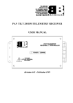
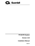
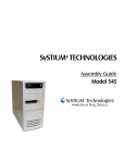
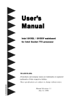
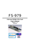
Endura KP915GV
ATX Motherboard
Quick Start Guide
The following information is provided to help you quickly configure, install and operate your
RadiSys KP915GV motherboard. Refer to the product manual for more detailed information.
The RadiSys KP915GV is an ATX-family motherboard that meets the ATX form factor specifications, is
based on the Intel® 915GV chipset, and support selected Intel® Celeron™ D and Pentium® 4 processors.
Features include 4 DIMM sockets, integrated video, system monitoring, three PCI, two x1 PCI-E, and one
ADD2 slots, eight USB 2.0 ports, and up to two optional Ethernet channels on a board measuring 9.6 x 12
inches.
Board Layout and Key Component Identification
59
58
57
56 55 54 53 52 51 50 49 48 47
46
1
45
2
44
3
43
4
42
41
5
40
6
39
7
38
8
37
9
36
10
35
11
34
12
33
32
(Optional)
13 14 15 16 17 18 19 20 21 22 23 24 25 26 27 28 29 30
31
© 2005 RadiSys Technology (Ireland) Ltd.
Endura KP915GV Guide
Component Identification
Description
Description
Description
1
Super IO
21
Ethernet port 1
(option)
41
USB port 2 header
2
Memory sockets
22
I/O panel USB port 7
42
USB port 3 header
3
Serial port 2 header
23
I/O panel USB port 8
43
USB port 4 header
4
Remote thermal sensor
24
Microphone input jack
44
SMBus header
5
CPU FAN power
connector
25
Audio line output jack
45
BIOS ROM writeprotect jumper
6
Chipset GMCH
26
Ethernet controller 1
(option)
46
Clear CMOS Jumper
7
775-pin socket for
processor
27
ADD2 slot
47
GPIO header
8
Clock generator
28
Ethernet controller 2
48
BIOS ROM (FWH)
9
System fan power
connector
29
PCI Express x1 slot
49
CPLD control logic
10
PS/2 mouse header
30
PCI slot 2.3
50
JTAG header
11
PS/2 keyboard header
31
HD Audio CODEC
51
I/O controller hub
(ICH6)
12
12V power connector
32
Stereo audio (CD) line
input header
52
Operation Mode
Jumper
13
PS/2 mouse (green)
33
Stereo audio
(microphone) input
header
53
Front panel header
14
PS/2 keyboard (purple)
34
Stereo audio line
output header
54
SATA connectors
15
Serial port
35
Buzzer
55
Chassis fan power
connector
16
Parallel port
36
1394 controller
56
Primary power supply
connector
17
VGA monitor
37
RTC battery
57
IDE connector
18
Ethernet port 2
38
1394 PHY
(TSB81BA3I)
58
TPM header
19
I/O panel USB port 5
39
1394 header
59
FDD connector
20
I/O panel USB port 6
40
USB port 1 header
© 2005 RadiSys Technology (Ireland) Ltd.
Endura KP915GV Guide
Quick Start
To begin operating your KP915GV motherboard, perform the
following:
• Read and save all instructions.
• Ensure that the jumper settings match your requirements.
• Attach all necessary peripheral devices to the appropriate
headers and connections on the board using the information
provided on the following pages.
• Power on the system.
• Run the BIOS setup utility (press <Delete> during POST) if you
need to change any settings to match your requirements.
Caution - There is a risk of explosion if
the battery is replaced with an incorrect type.
Dispose of used batteries according to the
manufacturer's instructions.
To avoid damage or injury, always
exercise the following precautions when
handling this product:
• Use a grounding wrist strap or other
static dissipating device.
• Power off the system.
• Disconnect all power cables
Power Supply Requirements
This board uses a 20-pin ATX power connector. In order to avoid damaging any devices, make sure that
they have been installed properly prior to connecting the power supply. It is recommended that the board
be used with a power supply that supports a minimum current load of 0.3A or less on the 5V supply
rail and 2A or less on the 3.3V supply rail (see note below).
Support for ATX12V power supplies
Supports hard- and soft-switched power supplies with jumper-less configuration
Note: This board with CPU and memory may draw as little as 400mA of 5V and 2A of 3.3V during
start-up (actual loads depend on installed devices). The power supply under consideration must be
verified as compatible with the projected total system start-up loads for these supply rails. If the
power supply minimum current level requirements are not at or below the level of current loads that
are actually drawn, unpredictable start-up operation may result, such as the power supply latching
off. If this occurs, the AC input to the power supply must be removed and re-attached or the power
supply switch cycled off and on, in order to turn the system back on.
Processor Support
The board supports both Intel® Celeron™ D 340/341 (2.93GHz 533MHz FSB 256K L2) and Pentium® 4
550/551 (3.4GHz 533/800MHz FSB 1MB L2) processors. Both the processor voltage and operating
frequency are automatically adjusted by the motherboard to suit the installed processor. A complete list of
tested processors is available from the RadiSys web page http://www.radisys.com.
CPU Installation:
Below is the CPU socket illustration. Follow these procedures to install a CPU.
Load lever
Load plate
Load cap
Load Stiffener
© 2005 RadiSys Technology (Ireland) Ltd.
Endura KP915GV Guide
1. Use thumb & forefinger to hold the lifted tab of the cap.
Lifted tab
2. Lift the cap up and pick to upload the cap completely from the socket.
3. Use thumb & forefinger to hold the hook of the load lever and pull the lever sideways to unlock it.
Correct
Wrong
Warning:
DO NOT use finger to lift the locking lever, as injury could occur to the finger and the socket could be damaged.
4. Lift up the lever. Use thumb to open the load plate. Be careful not to touch the contacts..
© 2005 RadiSys Technology (Ireland) Ltd.
Endura KP915GV Guide
5. Hold the CPU and tilt it to some degree since the contacts are designed to be hooked, and then match the triangle
marker to Pin 1 position as shown below. Carefully insert the CPU into the socket until it fits in place.
Alignment key
Pin 1 indicator
6. Close the load plate, and lightly push down the tongue side.
Lightly push down
the tongue side
7. Lower the lever and lock it to the load plate, then the CPU is locked in place.
CAUTION
Excessive temperatures will severely damage the CPU and system. Therefore, you should install
CPU cooling fan and make sure that the cooling fan works normally at all times in order to prevent
overheating and damaging to the CPU. Please refer to your CPU fan user guide to install it
properly.
© 2005 RadiSys Technology (Ireland) Ltd.
Endura KP915GV Guide
System Memory
Four 240-pin DIMM sockets are provided that support DDR2 400/533 MHz, non-ECC, unbuffered memory
modules in 256MB, 512MB, 1GB, and 2GB sizes, which may be installed as single DIMMs if desired. The
two memory channels are interleaved: Addresses are ping-ponged between the channels after each cache
line (64-B boundary). For dual interleaved mode, DIMMs must be installed in matched pairs, installed in
sockets with identical color (e.g. locations DIMM1 and DIMM3, then DIMM2 and DIMM4). If a total of 4GB of
DIMMs is installed, the maximum available memory will be approximately 3.24GB, with the balance of the
address space being consumed by other resources in the system. A complete list of tested memory is
available from the RadiSys web page http://www.radisys.com.
Memory Installation:
This motherboard includes four 240-pin slots with 1.8V for DDR2. You must install at least one memory bank to ensure
normal operation.
Installation of DDR2 Memory
1.
There is only one gap in the middle of the DIMM slot, and the memory module can be fixed in
one direction only. Unlock a DIMM slot by pressing the module clips outward.
2.
Align the memory module to the DIMM slot, and insert the module vertically into the DIMM slot.
DDR2 Memory bank
128 Pins
112 Pins
3. The plastic clips at both sides of the DIMM slot will lock automatically.
CAUTION
Be sure to unplug the AC power supply before adding or removing expansion cards or other
system peripherals, especially the memory devices, otherwise the motherboard or the system
memory might be seriously damaged.
© 2005 RadiSys Technology (Ireland) Ltd.
Endura KP915GV Guide
Video
The board directly supports VGA analog video output via the Intel integrated GMA 900 video controller. In
addition the ADD2 slot supports digital display adapters (ADD2 cards) that can support one additional device
(18-bit single-channel flat panel LVDS or an analog TV-Out or one DVI monitor). See the product manual for
further details.
Integrated Intel® GMA900 video controller
1. Intel IPD group Embedded Graphics or GMA (Extreme) drivers and video BIOS
Analog RGB output with DDC2B
1.
2.
Graphics resolution up to 2048 x 1536 pixels with 32-bit color support at 75Hz
15-pin D-sub connector
Network
A single Ethernet port is available, either 10/100 or 10/100/1000Mbit depending on the product version,
supporting remote boot, PXE and Wake-On-LAN capabilities. Connection to the network is achieved through
an RJ45 connector that has integral LED’s to provide link status information. If needed, a second
10/100/1000Mbit Ethernet port can be provided (with a second RJ45 connector).
Configuration
The majority of the configuration of the board is done through the setup utility built into the BIOS – discussed
later in this document. There are, however, a number of jumpers that control the operation of the board as
described below. Some jumpers are not fitted to certain products.
See the product manual for a depiction of the jumper positions and locations on the board.
Operation Mode Jumper (JP3)
This jumper selects one of the following operating modes for the motherboard (pins 1, 3, 5) and controls
write capability for the CPLD content (pins 2, 4, 6).
Normal Mode (Jumper between pins 1 & 3) This is the factory default position the jumper should be in for
normal operation of the motherboard.
Configure Mode (Jumper between pins 3 & 5) With the jumper in this position the motherboard automatically
runs the BIOS Setup utility regardless of the state of the Setup disable flag that can be set in
the BIOS defaults. In this mode, the CMOS RAM contents are ignored and the defaults are
used to configure the motherboard.
Recover Mode (No jumper) With no jumper installed on pins 1, 3, and 5 recovery mode is entered. The
motherboard does not boot and waits until a valid recovery diskette is detected and then
copies new BIOS into the ROM. The motherboard must be powered down and then repowered with the jumper in the normal position before normal operation can resume.
CPLD Write Enabled (Jumper between pins 2 & 4) In this position the contents of the CPLD can be
reprogrammed.
CPLD Write Protected (Jumper between pins 4 & 6) This is the factory default position. In this position, or
with no jumper on pins 2, 4, and 6, the contents of the CPLD are protected from
reprogramming.
BIOS Boot Block Write Protect Jumper (JP2)
(Jumper between pins 1 & 2) This is the factory default position. A jumper installed in this position. or no
jumper installed, enables changes to contents of BIOS ROM boot block (unlocked position). Some
motherboard applications may want to have boot block write-protected BIOS. This can be provided via the
BIOS boot block write protection jumper facility. If a jumper is installed between pins 2 & 3 (locked position),
the contents of BIOS ROM boot block cannot be changed in any way.
Clear CMOS Jumper (JP1)
(Jumper between pins 2 & 3) This is the factory default position. Either this position or no jumper installed, is
the normal operating configuration. Installing a jumper between pins 1 & 2 clears (resets) the CMOS.
© 2005 RadiSys Technology (Ireland) Ltd.
Endura KP915GV Guide
BIOS
The BIOS is based on Phoenix Award BIOS. Configuration of the board is achieved, in the majority of cases,
through BIOS settings. These can be viewed and modified using the BIOS set-up utility, which is provided to
perform system configuration changes and to display current settings and environment information. The
BIOS setup utility stores configuration settings in system non-volatile storage. Changes affected by BIOS
setup will not take effect until the system is rebooted.
Setup Utility
During the boot, pressing the 'DEL' key on the keyboard requests the BIOS Setup utility be launched once
the self-test is complete and before searching for a boot device. The Setup utility is provided to perform
system configuration changes and to display current settings and environment information. The Setup utility
stores configuration settings in system non-volatile storage. Changes affected by BIOS Setup will not take
effect until the system is rebooted. See the Product Manual for detailed information on settings and options.
Configuration Reset
Activating the Clear CMOS jumper produces a "reset system configuration" request and the BIOS loads the
default system configuration values during the next POST.
After power-up or reset, the BIOS perform a self-test (POST) that attempts to determine if further operation is
possible and that the detected configuration is expected. This process can complete normally or result in a
warning or an error. The boot process does not stop after a warning but displays a message on the primary
display device. If an error is detected, the boot process is halted. If possible, a message is displayed but
failures early on in the test can only be indicated by POST codes.
Once the initial part of the self-test process is completed, the display device is initialized and boot messages
can then be sent to the display. By default, the display is in Quietboot mode in which the customizable logo is
visible on screen. If the Quietboot mode is disabled (BIOS Setup) then sign-on and test progress messages
are visible. Pressing the 'TAB' key on the keyboard during a Quietboot switches the display to text mode providing the progress messages.
The BIOS will then search for boot devices in the order configured by the BIOS Setup and load an operating
system from the first boot device found. Control is then passed to the operating system and the motherboard
BIOS plays no further part in the boot except to provide run-time services.
POST Logo Change (OEM)
See the Product Manual for information needed to change the logo screen in the BIOS bin file.
CMOS Default Change
See the Product Manual for information needed to customize default CMOS (BIOS setup) settings.
Technical and Product Support
BIOS configuration, update, and set-up information, device drivers, tested memory and processor lists, and
other product and technical support documentation are available for download from the RadiSys Web site
http://www.radisys.com.
Note: It is recommended that only the drivers supplied by RadiSys be used as those posted on the device
manufacturer’s Web sites may not function correctly.
© 2005 RadiSys Technology (Ireland) Ltd.
Endura KP915GV Guide
Connector Descriptions
Operating Mode and CPLD Write Jumper (JP3)
Pin
1
3
5
Signal
NORMAL
GND
CONFIGURE
Pin
2
4
6
Signal
CPLD_TDI
JMP_CPLD_TDI
KEY
ATAPI Audio Headers (J1,J2,J3)
Pin Signal
1
LEFT CHANNEL
2
GND
3
GND
4
RIGHT CHANNEL
USB Internal Ports 4 & 4 (CN10, CN12, CN13,
CN14)
Pin Signal
1
+5V Fused
2
DATA3
DATA+
4
GND
5
GND
SMBus Header (J8)
Pin Signal
1
+3.3V
2
DATA
3
CLOCK
4
GND
Processor and System Fans (CN9,CN11, CN22)
Pin Signal
1
GND
2
+12V
3
TACHO
4
PWM
Front Panel Header (CN23)
Pin Signal
Pin
1
HDLED+
2
3
HDLED4
5
RESETSW6
7
RESETSW+
8
9
+5V Fused
10
11
12
Not Used
13
GND
14
15
PWRLED16
17
18
Not Used
19
PWRLED20
Signal
PWRLED+
PWRLED+
PWRSW+
PWRSWSPKR+
SPKRKEY
SPKRTAMPERSW+
TAMPERSW-
General Purpose I/O Header (J9)
Pin Signal
Pin Signal
1
GND
2
+5V Fused
3
PWM
4
GPIO20
5
GPIO21
6
GPIO22
7
GPIO10
8
GPIO11
9
GPIO12
10
GPIO13
11
GPIO14
12
GPIO15
13
GPIO16
14
GPIO17
15
16
KEY
Reserved
17
GND
18
GPI23
19
GND
20
GPI24
Keyboard & Mouse Headers (J4,J5)
Pin Signal
1
+5V Fused
2
DATA
3
GND
4
CLOCK
Remote Thermal Sensor (J12)
Pin Signal
1
DIODE+
2
DIODE-
Serial Port 2 Header (J7)
Pin Signal
Pin
1
DCD
2
3
RxD
4
5
TxD
6
7
DTR
8
9
GND
10
Signal
DSR
RTS
CTS
RING
KEY
ATX Power Connector (CN19)
Pin Signal
Pin
1
+3.3V
11
2
+3.3V
12
3
GND
13
4
+5V
14
5
GND
15
6
+5V
16
7
GND
17
8
PWROK
18
9
+5VSBY
19
10
+12V
20
Signal
+3.3V
-12V
GND
PSON#
GND
GND
GND
Not Used
+5V
+5V
ATX12V Power Connector (CN8)
Pin
1
2
Signal
GND
GND
Pin
3
4
Signal
+12V
+12V
© 2005 RadiSys Technology (Ireland) Ltd.