1
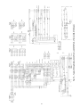
CONFIGURATION HEADER AND DIP SWITCH ASSEMBLY — The processor board is programmed to control a variety of air conditioning units. To tailor the processor to the particular unit being controlled, 2 devices are used. One is the
configuration header, and the other is the DIP switch assembly.
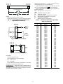
The configuration header (part no. 30GB660001) is a series
of 8 small wires that are broken or unbroken in a pattern to indicate several unique characteristics of the unit. The configuration header is factory set and should not be changed. Changing
the factory setting may cause the unit to malfunction.
The DIP switches configure the unit for several field-installed options, as well as for several other options that may be
unique to the unit. The DIP switches are located under a plastic
enclosure which must be removed for access. The switches can
be field adjusted, but must be adjusted only when the unit control circuit breaker is off.
All of the potentiometers must be set before the unit is started in order for the unit to function properly. See Start Up, Potentiometers section on page 27 for information on establishing
set points. Each of the potentiometers has a valid range that is
used by the control. The valid range is defined as the potentiometer’s resistance value that the control will not consider to
be in error. This is usually between 10% and 90% of the potentiometer’s total resistance. The control has been programmed
to accept an operational range for the potentiometer, which
may not be the same as the valid range.
The potentiometer locations and functions are as follows:
P1 — SUPPLY-AIR SET POINT — This potentiometer is
located on the display board. The supply-air set point is the
cooling mode control temperature which the VAV control system will attempt to maintain at Thermistor T1 by control of
economizer position and/or cycling unloaders and compressors.
P2 — ECONOMIZER POSITION — Economizer feedback
potentiometer is located on the economizer motor. The microprocessor is programmed to indicate an alarm if the travel during initialization is less than 10% of the total potentiometer’s
resistance. An alarm condition will also be signaled if the
potentiometer fails during operation, indicating that the
damper blades are stuck. If either situation occurs, the processor will try to drive the economizer dampers closed.
P3 — RESET LIMIT — This potentiometer is located on the
accessory board (provided standard from the factory) in the
unit main control box and establishes the maximum amount of
reset that can be applied to the supply-air set point (P1). Reset
is limited by the P1 default of 70 F. This potentiometer is used
only when accessory, field-installed temperature reset is used.
If temperature reset is used, DIP (dual, in-line package) switch
2 must be in the ON position.
P4 — DEMAND LIMIT — This potentiometer is located near
TRAN4 in the unit control box. The demand limit potentiometer is used only if accessory, field-installed demand limit is
used, and if DIP switch 5 is in the ON position. For single-step
demand limit, a field-installed 5 to 20 Kohm potentiometer and
switch must be used.
P5 — ECONOMIZER MINIMUM POSITION — This
potentiometer is on the accessory board (provided standard
from the factory) located in the unit main control box. This
potentiometer specifies the minimum opening position for the
optional economizer. If a fault condition is detected by the processor, an alarm condition will be signaled and the economizer
dampers will close.
P6 — WARM-UP SET POINT — This potentiometer is on
the accessory board (provided standard from the factory)
located in the unit main control box. This potentiometer establishes the set point temperature for the Morning Warm-Up
function. When the temperature is reached, Morning Warm-Up
is terminated and VAV operation begins. DIP switch 4 must be
in the ON position if morning warm-up heat is to be used.
P7 — SASP (SUPPLY AIR SET POINT) RESET TEMPERATURE — This 10 Kohm potentiometer is used only if the
accessory, field-installed temperature reset package is installed.
This potentiometer determines the temperature at which reset
will begin. It is located on the accessory temperature reset
board. DIP switch 2 must be in the ON position to enable
SASP reset.
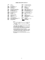
PROCESSOR BOARD OUTPUTS — The processor board
also controls outputs through the relay board. The relay board
plugs into the processor board using a ribbon cable.
In addition, the processor board controls the display board. The
display board is connected to the processor board by a ribbon
cable, and has an LED (light-emitting diode) display showing
the status of the unit and diagnostic information.
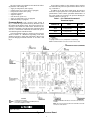
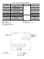
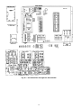
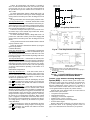
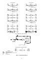
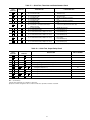
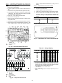
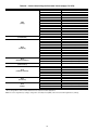
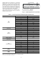
Relay Board — The relay board is used to control 24-v
and 115-v loads. See Fig. 5. The relay board is connected to the
processor board by a ribbon cable at pin J9. Electrical connections to the relay board are made through pins J5 (115 v) and J6
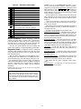
(24 v). The relay board has eight 24-v relays and five 115-v relays. See Table 3.
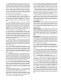
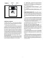
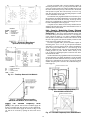
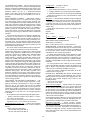
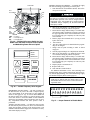
Display Board — The display board is located in the
main unit control box and is connected to the J10 port of the
processor board through a ribbon cable. The display board contains the supply-air set point potentiometer P1; a 2-digit, LED
display; and the display button (see Fig. 6). The LED display is
used to convey the operating information and operational error
codes.
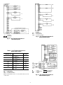
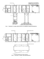
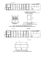
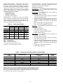
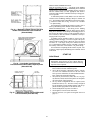
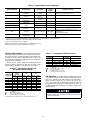
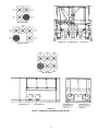
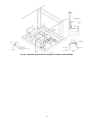
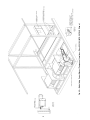
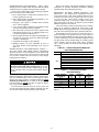
Thermistors — The processor uses up to 5 thermistors to
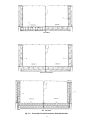
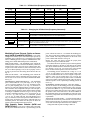
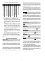
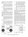
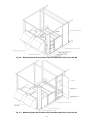
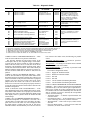
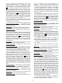
sense the temperatures at various points in the system. See Table 1 and Fig. 7-14. All the thermistors have identical temperature versus resistance and voltage drop characteristics, and are
monitored by the processor for a short or open circuit. The valid range for a thermistor is 362,640 to 219 ohms. Thermistor
details and locations are as follows:
T1 — SUPPLY-AIR TEMPERATURE THERMISTOR —
This thermistor is located in the unit supply fan discharge. It
provides information for the processor to stage the number of
capacity steps required to maintain a desired supply-air temperature.
T2 — RETURN-AIR TEMPERATURE THERMISTOR —
This thermistor is located in the mixed-air portion of the unit
cabinet. The thermistor’s primary function is to provide morning warm-up information. This sensor will also provide differential information for the processor during cooling operation
(such as the rate of change for a capacity step).
T3 — SATURATED CONDENSING TEMPERATURE,
CIRCUIT 1 — This thermistor is located on the condenser coil
return bend. See Fig. 13 and 14. It controls the staging of the
unit condenser fans based on the condensing temperature of
the refrigerant at the designated position on the condenser coil.
T4 — SATURATED CONDENSING TEMPERATURE,
CIRCUIT 2 — This thermistor is located on the condenser coil
return bend. See Fig. 13 and 14. It controls the staging of the
unit condenser fans based on the condensing temperature of
the refrigerant at the designated position on the condenser coil.
T10 — RESET TEMPERATURE — This thermistor is used
only if the accessory temperature reset package is used. It provides occupied space temperature information to the processor,
which determines whether or not reset is required. The thermistor is remotely mounted outside the unit in the conditioned
space.
5