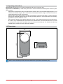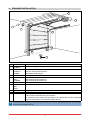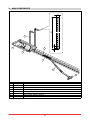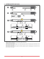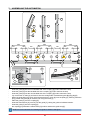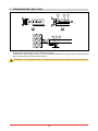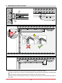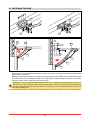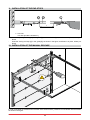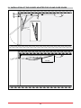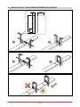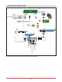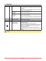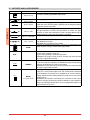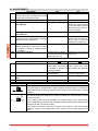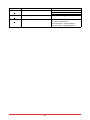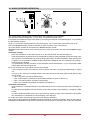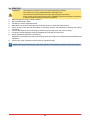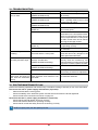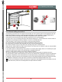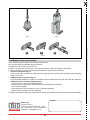
1
GLOBE
IP1839EN- rev. 2012-07-31
EN
Installation and
maintenance manual
for automations for
sectional overhead doors
and spring balanced
up-and-over doors.
(Original instructions)
DITEC S.p.A.
Via Mons. Banfi, 3 - 21042 Caronno Pertusella (VA) - ITALY
Tel. +39 02 963911 - Fax +39 02 9650314
www.ditec.it - [email protected]
INDEX
Subject
1. General safety precautions
2. Declaration of incorporation of partly completed machinery
Page
2.1 Machinery Directive
3. Technical data
3.1 Operating instructions
3.2Dimensions
4. Standard installation
5. Main components
6. Assembling belt and chain
7. Assembling the automation
8. Tensioning belt and chain
9. Mechanical installation
10. Fastening the arm
11. Installation of the end stops
12. Installation of the manual release
13. Installation of the GLOBEC adapter for up-and-over doors
14. Installation of the GLOBESI intermediate support
15. Electrical connections
16.Commands
17. Outputs and accessories
18.Settings
19. Radio receiver operation
20. Start up
21.Troubleshooting
22. Routine maintenance plan
23. Operating instructions
23.1General safety precautions
23.2Manual release instructions
3
4
4
5
6
6
7
8
9
10
11
12
13
14
14
15
16
17
18
19
20
22
23
24
24
25
25
26
CAPTION
This symbol indicates instructions or notes regarding safety issues which require particular attention.
i
This symbol indicates informations which are useful for correct product function.
This symbol indicates instructions or notes intended for technical and expert personnel.
STOP
This symbol indicates operations not to be effected for not compromise the correct operation of the
automation.
This symbol indicates options and parameters which are only available with the indicated item.
This symbol indicates options and parameters which are not available with the indicated item.
All right reserved
All data and specifications have been drawn up and checked with the greatest care. The manufacturer cannot
however take any responsibility for eventual errors, ommisions or incomplete data due to technical or illustrative
purposes.
IP1839EN • 2012-07-31
2
1. GENERAL SAFETY PRECAUTIONS
This installation manual is intended for professionally competent personnel only.
Installation, electrical connections and adjustments must be performed in accordance with Good Working
Methods and in compliance with applicable regulations.
Before installing the product, carefully read the instructions. Bad installation could be hazardous. The packaging
materials (plastic, polystyrene, etc.) should not be discarded in the environment or left within reach of children,
as these are a potential source of hazard.
Before installing the product, make sure it is in perfect condition.
Do not install the product in an explosive environment and atmosphere: gas or inflammable fumes are a serious
hazard risk.
Before installing the motors, make all structural changes relating to safety clearances and protection or segregation of all areas where there is risk of being crushed, cut or dragged, and danger areas in general.
Make sure the existing structure is up to standard in terms of strength and stability. The motor manufacturer
is not responsible for failure to use Good Working Methods in building the frames to be motorized or for any
deformation occurring during use.
The safety devices (photocells, safety edges, emergency stops, etc.) must be installed taking into account:
applicable laws and directives, Good Working Methods, installation premises, system operating logic and the
forces developed by the motorized barrier.
The safety devices must protect any areas where the risk exists of being crushed, cut or gragged, or where
there are any other risks generated by the motorized barrier.
Apply hazard area notices required by applicable regulations.
Each installation must clearly show the identification details of the motorized barrier.
Before making power connections, make sure the plate details correspond to those of the power mains.
Fit an omnipolar disconnection switch with a contact opening gap of at least 3 mm.
Make sure an adequate residual current circuit breaker and overcurrent cutout are fitted upstream of the electrical system. When necessary, connect the motorized barrier to a reliable earth system made in accordance
with applicable safety regulations.
During installation, maintenance and repair, interrupt the power supply before opening the lid to access the
electrical parts.
To handle electronic parts, wear earthed antistatic conductive bracelets. The motor manufacturer declines all responsibility in the event of component parts being fitted that are not compatible with the safe
an correct operation.
For repairs or replacements of products only original spare parts must be used. The installer shall provide all
information relating to automatic, manual and emergency operation of the motorized barrier, and provide the
user with operating instructions.
3
IP1839EN • 2012-07-31
2. DECLARATION OF INCORPORATION OF PARTLY COMPLETED MACHINERY
(Directive 2006/42/EC, Annex II-B)
The manufacturer DITEC S.p.A. with headquarters in Via Mons. Banfi, 3 - 21042 Caronno Pertusella (VA) ITALY declares that the automation for sectional doors type GLOBE:
- has been constructed to be installed on a manual gate to construct a machine pursuant to the Directive
2006/42/EC. The manufacturer of the motorized gate shall declare conformity pursuant to the Directive
2006/42/EC (annex II-A), prior to the machine being put into service;
-
conforms to applicable essential safety requirements indicated in annex I, chapter 1 of the Directive
2006/42/EC;
- conforms to the Low Voltage Directive 2006/95/EC;
- conforms to the Electromagnetic Compatibility Directive 2004/108/EC;
- technical documentation conforms to annex VII-B to the Directive 2006/42/EC;
- the technical file is managed by Renato Calza with offices in Via Mons. Banfi, 3 - 21042 Caronno Pertusella (VA) - ITALY;
- a copy of technical documentation will be provided to national competent authorities, following a suitably
justified request.
Caronno Pertusella, 13-12-2010
Silvano Angaroni
(Managing Director)
2.1 Machinery Directive
Pursuant to Machinery Directive (2006/42/CE) the installer who motorises a door or gate has the same obligations as the manufacturer of machinery and as such must:
- prepare the technical file which must contain the documents indicated in Annex V of the Machinery Directive;
(The technical file must be kept and placed at the disposal of competent national authorities for at least
ten years from the date of manufacture of the motorized gate);
- draft the EC declaration of conformity in accordance with Annex II-A of the Machinery Directive and deliver
it to the customer;
- affix the CE marking on the power operated gate in accordance with point 1.7.3 of Annex I of the Machinery
Directive.
IP1839EN • 2012-07-31
4
3. TECHNICAL DATA
GLOBE7
GLOBE10
Power supply
Absorption
Thrust
230 V~ / 50-60 Hz
0,7 A
500 N
Opening speed
0,18 m/s
Closing speed
0,12 m/s
Maximum load
Temperature
Degree of protection
7 m2
2760 mm
3820 mm [GLOBELV1]
3 - FREQUENT
S2 = 30 min
S3 = 50%
-20° C / +55° C
IP10
230 V~ / 50-60 Hz
1,2 A
900 N
0,15 m/s [chain]
0,18 m/s [belt]
0,10 m/s [chain]
0,12 m/s [belt]
10 m2
2760 mm
3820 mm [GLOBEL1-GLOBELV1]
3 - FREQUENT
S2 = 30 min
S3 = 50%
-20° C / +55° C
IP10
Control panel
F1 fuse
Motor power supply
Accessories power supply
70R
F1,6A
24 V= / 8 A
24 V= / 0,3 A
71R
F1,6A
24 V= / 12 A
24 V= / 0,3 A
Power supply
Absorption
Thrust
120 V~ / 50-60 Hz
1,4 A
500 N
Opening speed
0,18 m/s
Closing speed
0,12 m/s
Maximum load
Temperature
Degree of protection
7 m2
2760 mm
3820 mm [GLOBELV1]
3 - FREQUENT
S2 = 30 min
S3 = 50%
-20° C / +55° C
IP10
120 V~ / 50-60 Hz
2,4 A
900 N
0,15 m/s [chain]
0,18 m/s [belt]
0,10 m/s [chain]
0,12 m/s [belt]
10 m2
2760 mm
3820 mm [GLOBEL1-GLOBELV1]
3 - FREQUENT
S2 = 30 min
S3 = 50%
-20° C / +55° C
IP10
Control panel
F1 fuse
Motor power supply
Accessories power supply
70R
F3,15A
24 V= / 8 A
24 V= / 0,3 A
71R
F3,15A
24 V= / 12 A
24 V= / 0,3 A
Carriage maximum stroke
Service class
Intermittence
Carriage maximum stroke
Service class
Intermittence
GLOBE7J
5
GLOBE10J
IP1839EN • 2012-07-31
3.1 Operating instructions
Service class: 3 (minimum 10÷5 years of working life with 30÷60 cycles per day).
Applications: FREQUENT (for multi-family entrances or small condominiums with frequent vehicle or pedestrian access).
- Performance characteristics are to be understood as referring to the recommended weight (approx. 2/3 of
maximum permissible weight). When used with the maximum permissible weight a reduction in the above
mentioned performance can be expected.
- Service class, running times, and the number of consecutive cycles are to be taken as merely indicative.
Having been statistically determined under average operating conditions, and are therefore not necessarily
applicable to specific conditions of use.
- Each automatic entrance has variable elements such as: friction, balancing and environmental factors,
all of which may substantially alter the performance characteristics of the automatic entrance or curtail
its working life or parts thereof (including the automatic devices themselves). The installer should adopt
suitable safety conditions for each particular installation.
3.2Dimensions
490
124
208
i
NOTE: unless otherwise specified, all measurements are expressed in millimetres (mm).
IP1839EN • 2012-07-31
6
4. STANDARD INSTALLATION
8
RG5
²
.5 mm
+ 2x1 1.5 mm² ²
x
2
mm
4x0.5 .5 mm²
4x0
A
2
1
3
8
4
6
6
7
5
Ref.
Code
1 GLOBE7
GLOBE10
2 GLOBEL1
GLOBELV1
GLOBESI
3 LAMPH
4 ASB1
ASB2
GLOBESB
5 GOL4
6 XEL2
LAB4
LAB4S
7
8 BATK1
A
i
Description
Motor + control panel
Extension set for chain automation
Extension set for belt automation
Intermediate guide support
Flashing light
Kit for the external release cord with lock
Cord blocking device (2000 mm)
Cord blocking device (5000 mm)
Radio
Photocells
Safety edge
Buffer battery kit
Connect the power supply to an approved omnipolar switch with an opening distance
of the contacts of at least 3mm (not supplied).
The connection to the mains must be made via an independent channel, separated
from the connections to command and safety devices.
NOTE: the given operating and performance features can only be guaranteed with the use of DITEC
accessories and safety devices.
7
IP1839EN • 2012-07-31
5. MAIN COMPONENTS
500
30
7
10
4
20
2
1
3
5
6
Ref.
1
2
3
4
5
6
7
Code
IP1839EN • 2012-07-31
Description
24 V= motor with encoder
Fastening bracket
Slide carriage
Sliding guide
Fastening arm
Door section retention bracket
Control panel
8
6. Assembling belt and chain
1
A
B
C
2
D
3A
E
F
A
E
F
3B
E
F
A
E
F
-Attach the belt or chain [A] to the transmission [B] and slide [C].
-Assemble the belt stop [D].
-Fasten the two ends of the belt [A] to the release pin [E] through the couplings [F] in the direction of the
pin, as shown in the figure.
-Fasten the two ends of the chain [A] to the release pin [E] through the couplings [F] in the direction of the
pin, as shown in the figure.
9
IP1839EN • 2012-07-31
7. Assembling the automation
D
C
C
C
B
B
1
2
1066
370
1066
205
B
3
400
205
370
C
A
1066
400
A
D
B
E
205
370
F
G
D
H
E
I
F
J
-Insert the guide [B] into the non-bevelled side of the coupling [C] until it reaches the stop.
-Insert the guide [D] into the bevelled side of the coupling [C] until it reaches the stop.
-Insert the guide [D] into the non-bevelled side of the coupling [E] until it reaches the stop.
-
Lay out the belt or chain [A] and insert it into the carriage side of assembled guide [B]+[C]+[D]+[E].
-Mount the guide [B] on the drive unit and pass the belt or chain [A] over the pulley [H], blocking it with the
pin [I]. Attach the guide [B] to the drive unit using the screw [J].
-Place the guide [F] over the coupling [E].
-Insert the transmission [G] correctly into the guide [F], raising the guide to facilitate insertion.
-Insert the guide [F] into the coupling [E].
-the coupling [E] towards the transmission [G] until its reaches the guide stop [F].
i
NOTE: the correct direction for inserting the guide in shown in the figure.
IP1839EN • 2012-07-31
10
8. Tensioning belt and chain
C
B
1
A
2
B
C
A
1÷2
-Assemble the transmission unit as indicated in the figure.
-To tension the chain or belt correctly, 1÷2 mm should be left between the spring retainer [A] and the stop
[B], so that the spring [C] can function properly.
WARNING: over-tensioning the chain or belt will prevent the automatic system from functioning properly.
11
IP1839EN • 2012-07-31
9. MECHANICAL INSTALLATION
A
C
B
10÷100
45°
min 680
-Select and mark the point where the guide will be mounted on the wall and ceiling.
-Leaving the control unit on the floor, mount the guide [A] on the wall using the transmission support bracket
[B].
-Insert the retention brackets [C] and lock them in place with the screws provided.
-Raise the control unit and bend the brackets as necessary (excess parts can be removed), then attach to
the ceiling.
IP1839EN • 2012-07-31
12
10. Fastening the arm
B
B
A
A
F
max
200
C
C
20÷100
45°
G
D
F
E
A
45°
D
A
-Mount the door section retention bracket [A] on the top of the door, using the reinforcement angle brackets
[B] provided, if necessary.
-Release the automation as shown on page 27. Bring the slide [C] to the closed door and attach the arm [D]
to the slide [C] so as to form approximately a 45° angle with the upright section of the door. If necessary
adjust the length of the arm [D] using the extension [E].
WARNING: in order to open particularly high sectional doors completely, the attachment point [F] can be
moved 20 mm to 100 mm inwards from the point where the door section retention bracket [A] is fastened,
inserting a shim [G] if necessary (not provided, max. 200 mm), so as to increase the slide stroke and use
all of the available guide.
An angle of approximately 45° should always be kept between the arm and upright section of the sectional door.
13
IP1839EN • 2012-07-31
11. INSTALLATION OF the end stops
C
B
A
L
L = max 2760
max 3820 [GLOBEL1-GLOBELV1]
-Insert the opening end stop [A] in the guide [B], as shown in the figure, and fasten it in place, where preferred.
-Insert the closing end stop [C] in the guide [B], as shown in the figure, and fasten it in place, where preferred.
12. INSTALLATION OF the manual release
1
TYPE
E
DOOR
OF
CTUR
FA
MANU
YEAR
Y
GE
TA
VOL
SUPPL
ER
L NUMB
SERIA
2
In order to facilitate the release and movement of the sectional door, position the cord release near the handle,
as shown in the figure.
IP1839EN • 2012-07-31
14
min 20
max 210
13. INSTALLATION OF the GLOBEC adapter for up-and-over doors
min 900
15
IP1839EN • 2012-07-31
14. INSTALLATION OF the GLOBESI intermediate support
75
50
220
30
1
2
1
IP1839EN • 2012-07-31
2
16
15. ELECTRICAL CONNECTIONS
AUX
Transformer
Power supply
24 V~
ANT
SIG
JR4
F1
COM
PRG
GOL4
BIXMR2
BATK1
SO
JR3
Courtesy
light
JR2
Motor
24V=
ON
MM+
Black
Blue
OFF 1 2 3 4 5 6
POWER
ALARM
GLOBE10
SA
ENC
R1 TC
Electric lock
Lamp
Flashing light
Output 24 V= / max 0.3 A
+
Step-by-step
Safety re-opening
Stop
15 13 14 0 1 5 8 9
GLOBE10
The figure shows the main connections of the control panel 70R-71R.
17
IP1839EN • 2012-07-31
16.COMMANDS
1
Command
Function
5 N.O. STEP-BY-STEP
OPENING WITH
AUTOMATIC
CLOSING
OPENING WITHOUT
AUTOMATIC
CLOSING
1
8
1
9
N.C. REVERSE
SAFETY CONTACT
N.C. STOP
N.O. transmitters
STORAGE AND
CANCELLATION
PRG
Description
With DIP1=OFF, the closing of the contact activates opening
or closing operations in the following sequence: open-stopclose-open.
Note: if automatic closing is enabled, the stop is not permanent
but lasts for a duration set by TC.
With DIP1=ON and TC<MAX, the closing of the contact activates the opening operation.
With DIP1=ON and TC=MAX, the closing of the contact activates the opening operation.
Note: once the automation stops, the closing of the contact
performs the opposite operation to the one performed before
stop.
The opening of the safety contact triggers a reversal of motion
(re-opening) during closing.
The opening of the safety contact stops the current operation.
Warning: the BIXMR2 storage module must be inserted.
Transmitter storage:
- press the PRG key (the SIG LED comes on),
- transmit the transmitter to be stored (the SIG LED flashes),
- wait 10 s to complete storage (the SIG LED goes out).
Transmitter cancellation:
- press the PRG key for 3 sec (the SIG LED flashes),
- press the PRG key for another 3 sec (the SIG LED flashes
quickly).
WARNING: make a jumper for all the n.c. contacts if not in use. The terminals with the same number
are equal.
IP1839EN • 2012-07-31
18
17. OUTPUTS AND ACCESSORIES
Output
Value - Accessories
0 1 2 3 4 9 24 V= / 0.3 A
- +
14
0
LAMPH
24 V= / 25 W
GLOBE10
24 V= / 25 W
1
13
24 V= / 3 W
0
15
24 V= / 1.2 A max
15
0
12 V / 15 W
ANT
BIXAL
AUX
COM
BIXMR2
BAT
BATK1
2 x 12 V / 2 Ah
Description
Accessories power supply. Power supply output for external accessories, including automation status lamp.
Flashing light. Activated during opening and closing operations.
Internal courtesy light. A courtesy light that turns on for 180 seconds with every opening (total or partial), step-by-step and closing
command can be connected.
Automation status lamp (proportional).
The light switches off when the automation is closed; the light
switches on when the automation is open; the light flashes with a
variable frequency while the automation is operating.
Electric lock. With DIP5=ON, on with the door closed.
Electric lock. With a 12V electric lock, connect the supplied 8.2 Ω /
5 W resistance in series.
With DIP5=ON, on with the door closed.
Connect the supplied antenna wire (173 mm), or alternatively the
BIXAL antenna, using a coaxial cable, type RG58.
The control panel has one housing for plug-in cards such as a radio
receiver type, magnetic loops, etc.
Plug-in card operating is selected using DIP1.
WARNING: the plug-in cards must be inserted and removed with
the power supply disconnected.
The BIXMR2 storage module allows remote controls to be stored.
If the control panel is replaced, the BIXMR2 storage module being
used can be inserted in the new control panel.
WARNING: the storage module must be inserted and removed with
the power supply disconnected.
Battery operating. The batteries are kept charged when the power
supply is on. If the power supply is off, the control panel is powered
by the batteries until power is re-established or until the battery
voltage drops below the safety threshold. If this occurs, the control
panel turns off.
WARNING: the batteries must always be connected to the control
panel for charging. Periodically check the efficiency of the batteries.
NOTE: the operating temperature of the rechargeable batteries is
approximately +5°C/+40°C.
19
IP1839EN • 2012-07-31
18.ADJUSTMENTS
Description
OFF
Command 1-5 operation.
Step-by-step.
NOTE: it also sets operating mode of the
plugin cards connected on AUX.
Direction selection.
Opening towards gearmotor.
Disengagement on the closing stop 2 mm.
with JR2=ON.
DIP1
DIP2
DIP3
Disengagement on the closing stop 5 mm.
with JR2=OFF.
Automation status at power on.
Open.
Indicates how the control panel considers
automation when powered up.
DIP4
DIP6
Description
Reversal safety switch function.
OFF
With the automation blocked,
if the contact 1-8 is open, it
is possible to activate the
opening operation.
Automation type selection.
Up and over door with
counterweights.
Selection of maximum working force Normal closing force.
limit.
Incorporated radio receiver.
Disabled.
SO
JR2
JR3
JR4
R1
Trimmer
min
max
0
s
TC
0s
Closing towards gearmotor.
0,5 mm.
NOTE: use of the selection
is recommended to prevent
the sectional door from closing incompletely.
5 mm.
Closed.
NOTE: if the automatic closing function is not used,
preferably set DIP4=ON.
Enabled.
Electric lock release.
Disabled.
Before opening from closed door, a thrust
is included in closing to facilitate electric
lock release.
3 seconds preflashing.
Disabled during opening.
Enabled for both opening
Enabled only with automatic and closing.
closing with TC>3 s.
12
GLOBE10
DIP5
Opening.
ON
Disabled
IP1839EN • 2012-07-31
ON
With the automation blocked,
if the contact 1-8 is open,
any operation is impossible.
Sectional door or up and
over door with springs.
Reduced closing force.
Enabled.
Description
Force adjustment.
The control panel is equipped with a safety system that stops motion if an obstacle is
encountered during an opening operation and inverts the movement during a closing
operation.
Setting automatic closing time. From 0 to 120 s.
The counter starts when automation is opened and lasts for the entire duration set with
TC trimmer (100%).
Once a safety switch has been activated, the counter starts as soon as the safety
switch is released (for example, after passing through the photocells), and lasts for the
entire time set with TC trimmer (100%).
Note: after the activation of the stop command, once contact 1-9 has closed again,
automatic closing is only enabled after a total, partial or step-by-step opening command.
20
SIG
LED
On
Transmitter enabling/storage phase.
POWER ALARM Power supply on.
SA
At least one of the safety contacts is open.
21
Flashing
Reception of a radio transmission.
Cancellation of transmitters in progress.
Memory damaged.
Encoder not working.
Operations count performed (only when control panel is switched on):
each rapid flash = 1000 operations
each slow flash = 10000 operations
IP1839EN • 2012-07-31
19. Radio receiver operation
ANT
SIG
CH1
CH2
CH3
CH4
COM
PRG
1
2
10 s
3
The control panel is equipped with a radio receiver with a frequency of 433.92 MHz.
The antenna consists of a rigid wire, 173 mm long, connected to the ANT clamp.
It is possible to increase the range of the radio by connecting the antenna of the flashing lights, or by installing
the tuned BIXAL antenna.
NOTE: to connect the external antenna to the control panel, use a coaxial cable type RG58 (max 10 m).
Check that BIXMR2 storage module is inserted on COM connector of the control panel.
Up to 200 remote controls can be stored in the BIXMR2 storage module.
WARNING: if the radio receiver on the control panel is not used, set JR4=OFF and remove the BIXMR2 storage
module.
Transmitter storage:
-
press the PRG button on the radio receiver or on the control panel; the SIG LED lights up;
-
make a transmission by pressing one of the desired CH buttons of the transmitter (within the range of the
radio receiver). The transmitter is now stored. During this phase, the SIG LED flashes. When the SIG LED
is again lit up, it is possible to validate another transmitter. Validate all the new transmitters by making a
transmission as indicated;
-
you automatically exit the procedure 10 seconds after the last transmission, or you can press the PRG
button again (the SIG LED goes off).
Up to four CH keys of a single remote control can be stored:
-
if only one (any) CH key of the remote control is stored, command 1-5 (step-by-step/opening) is carried
out;
-
from two to four CH keys of a single remote control are stored, the functions matched with the CH keys
are as follows:
• CH1 = command 1-5 step-by-step/opening;
• CH2 = partial opening command, it causes the automation to open for about 1 m;
• CH3 = command to switch on/off the courtesy light;
• CH4 = stop command, equivalent to impulsive command 1-9.
Transmitter cancellation:
-
keep pressed for 3 s the PRG button on the radio receiver or on the control panel, the SIG LED begins to
flash;
-
to erase all the transmitters from the memory of the radio receiver keep pressed for 3 s again the PRG
button;
-
to erase a single transmitter, press one of the previously stored CH keys of the transmitter to be erased;
-
the cancellation is confirmed by the quick flashing of the SIG LED.
For further information see the user manual for GOL series transmitters.
If the control panel is replaced, the BIXMR2 storage module being used can be inserted in the new control panel.
WARNING: the BIXMR2 storage module must be inserted and removed with the power supply disconnected.
IP1839EN • 2012-07-31
22
20.START-UP
WARNING 1-
2-
3-
4-
5-
6-
7-
8-
9-
i
The operations related to point 5 are performed without safeties.
The trimmer can only be adjusted with the automation idle.
The automation automatically slows when approaching the end stops.
At every start-up the control panel receives a RESET and the first operation is performed
at reduced speed (automation position acquisition).
Make a jumper for the N.C. safety contacts.
Set TC=MAX and R1=MAX.
Use DIP2 to set the required direction.
Manually move the door and make sure the entire stroke is correct and without friction.
Switch on and check that the automation is operating correctly with subsequent opening and closing
commands.
Connect the safety devices (removing the relative jumpers) and check they work correctly.
If required, activate automatic closing and adjust the time with the TC trimmer.
Set the obstacle thrust with the R1 trimmer.
WARNING: check that the working forces exerted by the door wings are compliant with EN12453-EN12445
regulations.
Connect any other accessories and check they operate correctly.
NOTE: in the event of servicing or if the control panel is to be replaced, repeat the start-up procedure.
23
IP1839EN • 2012-07-31
21.TROUBLESHOOTING
Problem
Possible causes
The automation does not No power.
open or close.
(POWER ALARM led off).
Short circuited accessories.
(POWER ALARM led off).
Blown line fuse.
(POWER ALARM led off).
Safety contacts are open.
(SA led on).
The remote control does not work.
External safety devices not
activating.
The automation opens/closes briefly and then stops.
The remote control has limited range and does not
work with the automation
moving.
Remedy
Check that the control panel is powered correctly.
Disconnect all accessories from terminals 0-1 (voltage must be 24 V=) and
reconnect one at a time.
Replace F1 fuse.
Check that the safety contacts are closed correctly (N.C.).
Check the correct memorization of the
transmitters on the incorporated radio.
If there is a fault with the radio receiver
that is incorporated in the control panel,
the radio control code can be read by
removing the storage module.
Photocells are activated.
Check that the photocells are clean
(SA led on).
and operating correctly.
The automatic closing does not work. Check that the TC trimmer is not set at
the maximum.
Incorrect connections between the Connect N.C. safety devices together in
photocells and the control panel.
series and remove any bridges on the
control panel terminal board.
Encoder disconnected, false encoder Check that the encoder is connected
contacts, encoder fault.
correctly, clean the contacts by con(POWER ALARM led flashing).
necting and disconnecting the encoder
plug on the contacts, replace encoder.
Motor leads crossed.
Check the motor leads.
(POWER ALARM led flashing).
There is friction.
Manually check that the automation
moves freely, check the R1 adjustment.
The radio transmission is impeded by Install the antenna outside. Substitute
metal structures and reinforced con- the transmitter batteries.
crete walls.
22. ROUTINE MAINTENANCE PLAN
Perform the following operations and checks every 6 months according to intensity of use of the automation.
Disconnect the 230 V~ power supply and batteries (if present):
- Clean and lubricate the moving parts.
- Check the stability of the automatic system and that nuts and screws are all well tightened.
- Check the electrical connections as shown on page 18.
Reconnect the 230 V~ power supply and batteries (if present):
- Check that the manual release functions correctly.
- Check that obstacle detection is operating correctly.
- Check that all control and safety functions are working correctly.
i
NOTE: for spare parts, see the spares price list.
IP1839EN • 2012-07-31
24
DETACH AND DELIVER TO THE CUSTOMER
GLOBE
23. Operating instructions
23.1 General safety precautions
The following precautions are an integral and essential part of the product and must be supplied to the user.
Read them carefully since they contain important information on safe installation, use and maintenance.
These instructions must be kept and forwarded to all possible future users of the system.
This product must only be used for the specific purpose for which it was designed.
Any other use is to be considered improper and therefore dangerous. The manufacturer cannot be held responsible for any damage caused by improper, incorrect or unreasonable use.
Avoid operating in the proximity of the hinges or moving mechanical parts.
Do not enter within the operating range of the motorized door while it is moving.
Do not block the movement of the motorized door since this may be dangerous.
Do not allow children to play or stay within the operating range of the motorized door.
Keep remote controls and/or any other control devices out of the reach of children in order to avoid possible
involuntary activation of the motorized door.
In the event of fault or malfunctioning of the product, turn off the power supply switch, do not attempt to repair
or intervene directly and contact only professionally competent personnel.
Failure to comply with the above may cause a dangerous situation.
All cleaning, maintenance or repair work must be carried out by professionally competent personnel.
To ensure that the system works efficiently and correctly, the manufacturer’s indications must be complied with
and routine maintenance of the motorized door must be performed by professionally competent personnel.
In particular, regular checks are recommended in order to verify that the safety devices are operating correctly.
All installation, maintenance and repair work must be documented and made available to the user.
For the correct disposal of electric and electronic equipment, waste batteries and accumulators, the user
must take such products to the designated municipal collection facilities.
25
IP1839EN • 2012-07-31
1
Fig. 2
2
3
Fig. 3
23.2 Manual release instructions
Carry out blocking and release with the motor switched off.
Do not enter within the operating range of the door.
If released, the door may move on its own.
NOTE: to remove power from the door, disconnect the power supply and batteries (if present).
In case of emergency, perform the following operations to open the door manually:
- Internal cord release (fig. 1):
pull the cord down until the lock release lever is actioned, then open the door manually while still pulling
down on the cord.
- ASB2 external cord release (fig. 2):
turn the release handle 90° in either a clockwise or anti-clockwise direction, then open the door manually.
- ASB1 external cord release with key (fig. 3):
- turn the key 90° in an anti-clockwise direction;
- extract lock block and pull the cable until the lock release lever is actioned;
- move the door slightly;
- insert the block in the lock and turn 90° in a clockwise direction;
- remove the key and open the door manually.
To restore motorized functioning, move the door manually; the release mechanism will reconnect automatically.
TM
Installer:
DITEC S.p.A.
Via Mons. Banfi, 3
21042 Caronno Pertusella (VA) - ITALY
Tel. +39 02 963911 - Fax +39 02 9650314
www.ditec.it - [email protected]
IP1839EN • 2012-07-31
26
DETACH AND DELIVER TO THE CUSTOMER
Fig. 1
27
IP1839EN • 2012-07-31
TM
DITEC S.p.A. Via Mons. Banfi, 3 21042 Caronno P.lla (VA) Italy Tel. +39 02 963911 Fax +39 02 9650314
www.ditec.it [email protected]
DITEC BELGIUM LOKEREN Tel. +32 9 3560051 Fax +32 9 3560052 www.ditecbelgium.be DITEC DEUTSCHLAND OBERURSEL
Tel. +49 6171 914150 Fax +49 6171 9141555 www.ditec-germany.de DITEC ESPAÑOLA ARENYS DE MAR Tel. +34 937958399
Fax +34 937959026 www.ditecespanola.com DITEC FRANCE MASSY Tel. +33 1 64532860 Fax +33 1 64532861 www.ditecfrance.com
DITEC GOLD PORTA ERMESINDE-PORTUGAL Tel. +351 22 9773520 Fax +351 22 9773528/38 www.goldporta.com DITEC SWITZERLAND
BALERNA Tel. +41 848 558855 Fax +41 91 6466127 www.ditecswiss.ch DITEC ENTREMATIC NORDIC LANDSKRONA-SWEDEN
Tel. +46 418 514 50 Fax +46 418 511 63 www.ditecentrematicnordic.com DITEC TURCHIA ISTANBUL Tel. +90 21 28757850
Fax +90 21 28757798 www.ditec.com.tr DITEC AMERICA ORLANDO-FLORIDA-USA Tel. +1 407 8880699 Fax +1 407 8882237
www.ditecamerica.com DITEC CHINA SHANGHAI Tel. +86 21 62363861/2 Fax +86 21 62363863 www.ditec.cn